Abstract
Due to the time-varying nonlinear dynamic, uncertain model and hysteresis characteristics of the pneumatic artificial muscle (PAM) actuator, it is not easy to apply model-based control algorithms for monitoring, as well as controlling, the operation of systems driven by PAM actuators. Hence, the main aim of this work is to propose an intelligent controller named adaptive sliding controller adding compensator (ASC + C) to operate a robotic arm, featuring a pneumatic artificial muscle actuator, which assists rehabilitation exercise of the elbow joint function. The structure of the proposed controller is a combination between the fuzzy logic technique and Proportional Integral Derivative (PID) algorithm. In which, the input of fuzzy logic controller is the sliding surface, meanwhile, its output is the estimated value of the unknown nonlinear function, meaning that the model-based requirement is released. A PID controller works as a compensator with online learning ability and is designed to compensate because of the approximate error and hysteresis characteristic. Additionally, to improve convergence and to obtain stability, a fast terminal sliding manifold is introduced and online learning laws for parameters of the controller are attainted through the stable criterion of Lyapunov. Finally, an experimental apparatus is also fabricated to evaluate control response of the system. The experimental result confirmed strongly the ability of the proposed controller, which indicates that the ASC + C can obtain a steady state tracking error less than 5 degrees and a position response without overshoot.
1. Introduction
Nowadays, physiotherapy is one of the important treatments for rehabilitation of mobile function of patients caused by diseases, accidents and neurologic problems. Hence, in recent years, the need for using machineries or devices for rehabilitation purpose increased. Some commercial exercise machineries for this purpose are produced by various companies [1,2]. In addition, with the development of technology, robot or robotic devices used in rehabilitation therapies have been studied and proposed by engineers and researchers [3,4]. Most of the actuators, which are often used in rehabilitation robots, are electrical motors [5,6,7,8] pneumatic cylinders [9,10]. In addition, pneumatic artificial muscle (PAM) actuators offer significantly promising application in robot-assisted rehabilitation. For example, a five-degree of freedom exoskeleton wearable robot featuring pneumatic artificial muscle, which assists shoulder elevation, humeral rotation, elbow extension, forearm supination and wrist extension, was designed by authors presented in [11]; Nuchkrua et al. [12] developed and experimented a robot hand for rehabilitation application. Prado et al. [13] designed and experimentally evaluated a PAM actuator for an exoskeleton application, showing that the hip and knee joints can be turned to create the sagittal movements. Wang et al. [14] applied a PAM actuator to design a wearable robotic glove, meeting the requirement for stroke rehabilitation. Zhong et al. [15] performed an optimal design and successfully experimented with an ankle rehabilitation robot driven by pneumatic artificial muscle. Besides, PAM actuators have been also presently studied for application in respiratory management as presented by Horvath et al. [16] in which PAM actuators are used to generate the contractile forces for the diaphragm displacement down toward the abdominal space. However, in order to operate PAM actuators, it requires accessories such as compressor, valves, pressurized gas tanks, indicating that the physical structure of systems driven by PAM actuators is bulky. Mirvakili et al. [17] designed a simple mechanism for operating pneumatic artificial muscle actuator without the use of compressor, valves, pressure-regulating equipment, etc. With this solution, pressure inside a PAM actuator is generated through liquid-to-gas phase transition of a liquid. Miriyev et al. [18] proposed an artificial muscle that is expended or contracted by being electrically driven through using a spiral-shaped resistive wire passing inside the actuator.
Indeed, a PAM actuator is one of the most promising actuators for industrial application and devices because it can offer many merits, such as compliant behavior, soft and flexible structure, high power to weight ratio, lightweight, etc. However, there still exists significant drawbacks that are time-varying nonlinear dynamics and hysteresis characteristics [19,20] which may cause difficulties for applying traditional control algorithms such as Proportional Integral (PI), PID, linear control techniques or model-based controllers to manage the operation of PAM actuators. In recent years, the nonlinear control algorithms for PAM actuators have been proposed based on neural network [21,22], backstepping control [23]. As is well known, the sliding mode control technique is one of the power methods for controlling the nonlinear dynamic system, uncertainties and external disturbance system [24]. However, the advantage of the traditional sliding mode control algorithm is that it needs an accurate dynamic model of the system and model parameters are known. This may cause difficulties to realize a compliant and uncertain system. Therefore, advanced control algorithms have been recently attracted by researchers. Shi et al. [25] proposed a controller for a parallel platform based on a PAM actuator, comprising sliding mode controller and fuzzy logic controller. Rezoug et al. [26] experimentally investigated the control response of nonsingular terminal sliding mode controller for a robot arm driven by a PAM actuator. Lin et al. [27] built a hysteresis model and proposed a feedback controller based on PI model to improve the tracking response of the dual PAM system. An adaptive controller based on a nonlinear extended state observer for the motion platform using a PAM actuator was designed by [28], showing that effects of the lead zones of the PAM are compensated by designing control law.
In addition, fuzzy logic control technique has been applied to control systems using pneumatic artificial muscle actuator. Chandrapal et al. [29] developed a self-organizing fuzzy controller for position and force control of a PAM actuator. The results are that the control response can effectively track reference signals without oscillation. Nuchkrua et al. [30] designed an intelligent controller based on the fuzzy logic algorithm and traditional PID algorithm, achieving the desirable dynamic performance targets of the system driven by a PAM actuator. Robinson et al. [31] designed a fuzzy controller for controlling lift robotic manipulation, responding to large variation of the load over a large range of motion. Wang et al. [32] proposed an adaptive fuzzy backstepping control for an anthropomorphic arm system, which ensures the stable and adaptable motion of the system. The control response of a haptic system using a PAM actuator was realized by Wu et al. [33] through an adaptive fuzzy sliding mode controller, obtaining the fidelity feeling of the reflection force.
In this paper, we describe a physical structure and dynamic model of an exercise-assisted robotic arm driven by a pneumatic artificial muscle for the elbow joint rehabilitation. An intelligent controller based on the sliding mode control algorithm is proposed and experimentally evaluated to obtain the wanted response and fast convergence. The paper is arranged as follows. Section 2 presents the structure and dynamic model of the robotic arm. An adaptive controller based on the sliding mode control algorithm and fuzzy logic technique will be proposed in Section 3. Control performances will then be experimented in Section 4. Finally, Section 5 shows the conclusions of the paper.
2. Dynamic Model of Robotic Arm
Firstly, a 3D model of the exercise-assisted robotic arm for elbow joint rehabilitation is described in Figure 1a. Patients can sit on the seat while the upper arm is supported by a fixed plate through fixed belts; the forearm is fixed on a movable plate rotating around the hinge joint. The angular position of the movable plate can be adjusted by introducing a mechanism including a pneumatic artificial muscle actuator (DMSP-20-300N-RM-CM) connected in parallel with a coil spring. Each end of the spring and PAM actuator is fixed on the fixed plate, the other ends are connected together via the gear belt and pulley system, as shown in Figure 1b. The length of the actuator can be adjusted by supplying the compressed air through a proportional pneumatic valve (MPYE-5-1/8HF-710B) manufactured by Festo Corporation. The orifice area of valve depends on the control voltage signal which is sent from the computer through an National Instrument (NI) card 6221 working as a Digital/Analog (A/D) converter. The actual angular of the movable plate is detected by using a rotary encoder with the resolution of 0.10 which is placed at the hinge joint and sends the feedback to the controller.
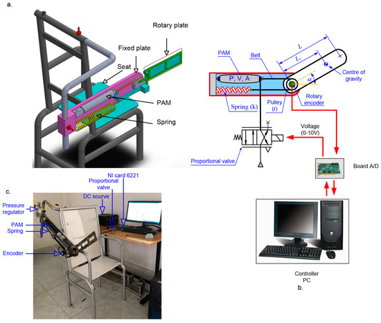
Figure 1.
(a) 3D model of the exercise-assisted robotic arm; (b) block diagram of operation principle; (c) photo of the exercise-assisted robotic arm.
Next, in the case of the PAM actuator which is inflated by a compressed air flow with pressure P, the result is that the bellow volume is changed by an amount dV and the length of the PAM actuator is shorten by an amount dL. The work carried out by an actuator is expressed in [34], as below:
in which P is the absolute air pressure in the PAM, Patm is the atmosphere pressure and F is the axial force.
The length and diameter of the cylindrical part of actuator are determined as follows:
and
with θ is the angle between the thread and axis of the PAM actuator, b is the thread length, n is the turn number of the thread.
Substituting Equations (2) and (3) into Equation (1), the axial force generated by the PAM actuator is expressed as a function of the angle θ, as follows:
Besides, the length of the PAM actuator can be written as a function of the angle position α of the movable plate:
where Lo is the initial length of the PAM, r is radius of the pulley.
The angle is expressed as below:
The axial force is rewritten as follows:
Besides, based on thermodynamic theory and ideal gas state equations [35], the internal energy change (U) of gas in the PAM actuator is determined as follows:
From PV = mRT, we have:
herein, Gin and Gout are the entering and leaving air mass flow rates in kg/s, m is the air mass in kg, cp and cv are the specific heat capacity at the constant pressure and volume, Ts and T are the temperature of the supplied air source and the compressed air in actuator in K, dw is given in Equation (1), h is the heat transfer coefficient in J/(m2 K), A is the heat exchange surface area in m2 and ΔT is the temperature difference between internal air and PAM wall in K, R is the air constant in J/(kg K). It is also noted that a “dot” denotes the time derivative.
Substituting Equation (8) into Equation (9), the pressure change in the PAM actuator is obtained as follows:
The entering and leaving air mass flow rates are expressed by:
in which and are the opening areas of valve orifice for entering and leaving compressed air, respectively. Ps is the supplied air source. ψ(φ) is the flow function given by:
The opening area of the valve orifice is proportionate to the control voltage signal (u) as given in [36], we have:
where Amax is the maximum opening area of the valve orifice, umax is the maximum control voltage signal of the valve.
Thus, from Equations (11)–(13), the pressure change equation is rewritten as follows:
Finally, the dynamic of the movable plate is presented as follows:
where M and I are the equivalent mass and inertia moment of the movable part including the mass of the movable plate and forearm, Lc is the distance between the hinge joint and center of gravity of the movable part, k is the stiffness of the coil spring.
By incorporating Equations (7), (14) and (15) the dynamic equation of the movable plate is re-expressed in term of state variable space as follows:
in which are the state variables and
Equation (16) reveals that the state variables of the system can be adjusted by changing the voltage supplied to the coil spring of the proportional valve. Hence, the angular position of the movable plate can obtain the desirable position by controlling the voltage signal. An intelligent controller for controlling the angular position will be designed in next section.
3. Controller Design
A sliding surface (s) is defined as follows:
where the tracking error between a desirable position (αd) and a real position (α) is presented by the notation “e”. λ1 is the positive sliding constant.
As is known, the structure of a sliding algorithm includes two independent stages: one is termed the reaching motion, the other is known as the sliding motion. To obtain fast finite-time convergence and anti-buffeting characteristics, a reaching law is designed as follows:
where λi is the design constant with I = 2, 3, 4.
From Equation (18), the time (tr) that moves from s(0) ≠ 0 to s(tr) = 0 is determined by solving Equation (18) as follows:
To ensure finite reaching time, λ2, λ3 > 0 and 0 < λ4 < 1.
From Equation (17), the time derivative of the sliding surface is written as below:
in which
Assuming that the air pressure (P) in the PAM actuator and temperature (Ts) of the air source are bounded, meaning the pressure is within (Patm ≤ P≤ Ps) and Ts < Tsmax.
In addition, F(x1,x2,x3,t) and G(x1,x2,x3,t) are assumed as unknown nonlinear functions, among them, the boundary of G(x1,x2,x3,t) is known and determined as follows:
with
Letting
in which is the normal value and known, is uncertainty.
Additionally, the fuzzy logic technique is used to estimate the function F(x1,x2,x3,t) as follows:
Ri if x1i is A1 and x2i is A2,…, xni is An then y is Bi, where Ri is the ith rule, Aj (j = 1…n) is the fuzzy set of the input variable xj, Bi is the fuzzy set of the output variable y.
By using the product law and center average defuzzification, the output of the fuzzy system is expressed as follows:
where is the membership function of input variable xj, yi is the center of the membership function the triangle type membership functions are employed for the linguistic state of input variable as shown in Figure 2 in which the linguistic state includes big negative (BN), middle negative (MN), small negative (SN), zero (Z), small positive (SP), middle positive (MP), big positive (BP).
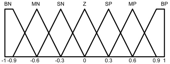
Figure 2.
Membership functions of the input variables.
To reduce the number of fuzzy law, the tracking error e(t) and the error change rate are integrated in the sliding surface as given in Equation (17), hence only variable s is considered as the input signal of the fuzzy system. Equation (23) is simplified as follows:
in which
Accordingly, Equation (24) is consider as an approximate function of F(x1,x2,x3,t). Then, substituting Equations (22) and (24) into Equation (20), we have:
In addition, there may exist approximate error, hence a compensator based on PID algorithm is presented as follows:
where
Combining Equations (18), (25) and (26), the total control law may be designed as follows:
where η is the positive constant, is the estimated state of θ.
Stability analysis:
Considering the Lyapunov function given by Equation (28):
herein, δ1 is the symmetric positive definite matrix, δ2 is the positive learning rate and .
Then substituting Equations (25) and (27) into the time derivative of V, yields
The update laws are selected as below:
in which ζ is the positive constant and is introduced to keep the parameter , which is bounded [37].
Accordingly, Equation (15) is rewritten as follows:
As a result of and , hence:
In order to obtain , the constant η must satisfy the following condition:
Correspondingly, the stability is always guaranteed in stable criterion of Lyapunov and the system will reach the sliding surface in finite time. The overall control block diagram of the robotic arm is presented in Figure 3.
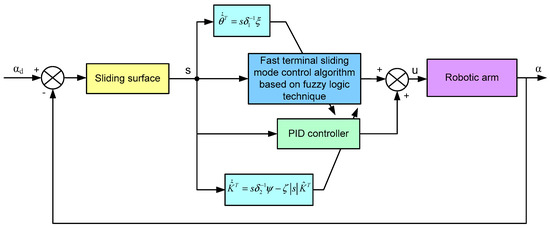
Figure 3.
Control block diagram for the robotic arm.
4. Experimental Evaluation
The experimental model is setup as shown in Figure 1c in which the specifications of the equipment are listed in Table 1, while parameters of the controller are given in Table 2. Herein, three types of the desirable trajectories, comprising step, ramp and sinusoid, are used to verify the control performance of the system, which is controlled by the proposed controller and the adaptive sliding mode controller without the compensator named adaptive sliding controller (ASC).

Table 1.
Specifications of the experimental equipment.
Table 2.
Parameters of controller.
4.1. Results on the 60° Step Command
The angular position response of the movable plate controlled by the proposed control is denoted by the solid line, meanwhile the response controlled by the ASC is plotted by the dashed line as shown in Figure 4a (detailed annotation of line types is shown in bottom-right panel of the Figure 4a). As observed, the tracking response of the proposed controller follows well the reference with the steady-state tracking error 0.5°, as seen in Figure 4b. The tracking effectiveness of the ASC without compensator is reduced, specifically the maximum tracking error 2.2°. This implied that the proposed controller can compensate effectively due to nonlinear effects as well as hysteresis behavior.
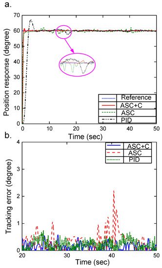
Figure 4.
(a) Time history of angular position; (b) steady-state tracking error.
In addition, the control response of the system is realized by the PID controller in which the parameters Kp = 5.76 Ki = 1.23 and Kd = 0.025 are chosen by trial and error method. As seen in Figure 4, although the tracking error of the PID controller is lower than that of the ASC, its overshoot is high. Hence, settling time is much larger than that of the ASC + C. This result confirms that the proposed controller obtains fast convergent rate and high tracking effectiveness. The estimated value of the approximated function F(x1,x2,x3,t) based on fuzzy logic technique is presented in Figure 5. It is noteworthy that in this case the approximated function is almost not changed at the steady state.
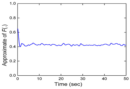
Figure 5.
Estimated value of approximated function F(x1,x2,x3,t).
4.2. Results on Ramp Command
In this case, a desirable trajectory increased from 10° to 110° is considered to evaluate the proposed controller. The control result of the movable plate is shown in Figure 6 in which the dot line presents the wanted signal, the dashed line denotes the response of the controller without compensator and the solid line exhibits the proposed controller. It can be observed that, because of the difference between the initial state and wanted signal, the response of the control system cannot track the desirable signal at the beginning time. After 1 s, the control response is in good agreement with the wanted trajectory. However, tracking quality of the ASC is lower than that of the ASC + C. As seen in Figure 6b, the maximum tracking error of the ASC is approximately 7° whilst the ASC + C can offer error lower than 1°. At the time t = 48 s, a notch appears in the response of the ASC; this is due to the effect of sudden change of the direction of the gravity moment. As presented in Figure 1b, in the case of α < 90°, the gravity moment is the opposite of the moment created by the axial force of the PAM actuator, as α > 90° both these moments are the same direction.
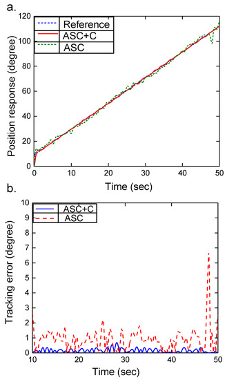
Figure 6.
(a) Angular position response of the movable plate for ramp command; (b) steady-state tracking error.
4.3. Results on Sinusoidal Command
This case will deal with the track task of 1Hz in frequency and 40° in amplitude sinusoidal signal. By applying the proposed control law, the estimated value of the unknown nonlinear function F(x1,x2,x3,t) is shown in Figure 7 and control response of the movable plate is presented in Figure 8 (the notation of types of lines is presented in each panel of Figure 8). It is noteworthy that the adaptive sliding mode controller with compensator maintains the desirable response, while by applying controller without compensator, the angular response cannot effectively track desirable trajectory. As observed, the response of the ASC occurs attenuation in amplitude. Hence, its tracking accuracy can only reach around 10°. With compensative ability, the tracking error of the proposed controller is smaller than 3.5°.
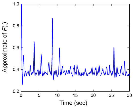
Figure 7.
Approximation of F(x1,x2,x3,t).
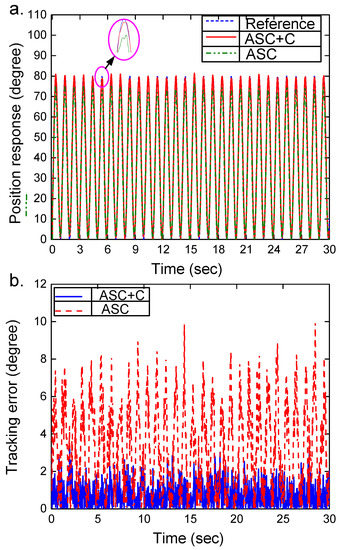
Figure 8.
(a) Angular position response of the movable plate for sinusoidal command; (b) steady-state tracking error.
5. Conclusions
Dynamic model of a robotic arm featuring the pneumatic artificial muscle actuator was built and presented in term of the state variable space. The adaptive fast terminal sliding mode controller was developed. The proposed controller includes two main control laws. One is called the reaching law in which the fuzzy logic technique is employed to approximate the nonlinear unknown function. The other is considered as compensated control law based on the PID algorithm. In order to attain the fast finite-time convergence, a terminal sliding mode manifold was introduced. The stability of proposed controller was analyzed in the sense of Lyapunov theory. Based on this analysis, the adaptive laws for the parameters of the fuzzy model were obtained. The experimental apparatus of the robotic arm was set up for evaluating control response of the proposed controller. Experimental results proved that the proposed controller successfully works with the nonlinear dynamic and uncertain parameters. Namely, the steady state tracking error of the robotic arm controlled by the ASC with compensator is smaller than 5 degrees, whilst by applying the ASC without compensator the robotic arm has tracking error higher than 5 degrees. Additionally, the settling time of the ASC + C is lower than that of the PID controller and the overshoot of the proposed controller almost disappeared.
Author Contributions
Conceptualization, T.D.L.; methodology, T.D.L. and H.T.N.; software, V.C.T.; validation, T.D.L. and H.T.N.; formal analysis, V.C.T.; investigation, T.D.L.; resources, T.D.L.; data curation, T.D.L.; writing—original draft preparation, T.D.L. and H.T.N.; writing—review and editing, T.D.L.; visualization, T.D.L., V.C.T. and H.T.N.; supervision, T.D.L. All authors have read and agreed to the published version of the manuscript.
Funding
This research was funded by Industrial University of Ho Chi Minh City, grant number 20/1.1CK02.
Conflicts of Interest
The authors declare no conflict of interest.
References
- Medical, X. 2019. Available online: https://www.xiangyumedical.com (accessed on 22 November 2020).
- Kinetec. 2019. Available online: https://kinetecuk.com/ (accessed on 22 November 2020).
- Belforte, G.; Eula, G.; Ivanov, A.; Sirolli, S. Soft Pneumatic Actuators for Rehabilitation. Actuators 2014, 3, 84–106. [Google Scholar] [CrossRef]
- Tiboni, M.; Borboni, A.; Faglia, R.; Pellegrini, N. Robotic rehabilitation of the elbow based on surface electromyography signals. Adv. Mech. Eng. 2018, 10. [Google Scholar] [CrossRef]
- Nef, T.; Riener, R. Shoulder actuation mechanisms for arm rehabilitation exoskeletons. In Proceedings of the 2nd IEEE RAS & EMBS International Conference on Biomedical Robotics and Biomechatronics, Scottsdale, AZ, USA, 19–22 October 2008. [Google Scholar]
- Yue, Z.; Zhang, X.; Wang, J. Hand rehabilitation robotics on poststroke motor recovery. Behav. Neurol. 2017, 2017, 3908135. [Google Scholar] [CrossRef]
- Aggogeri, F.; Mikolajczyk, T.; O’Kane, J. Robotics for rehabilitation of hand movement in stroke survivors. Adv. Mech. Eng. 2019, 11. [Google Scholar] [CrossRef]
- Torrealba, R.R.; Udelman, S.B.; Rojas, E.D.F. Design of variable impedance actuator for knee joint of a portable human gait rehabilitation exoskeleton. Mech. Mach. Theory 2017, 116, 248–261. [Google Scholar] [CrossRef]
- Kirihara, K.; Saga, N.; Saito, N. Upper limb rehabilitation support device using a pneumatic cylinder. In Proceedings of the 34th Annual Conference of IEEE Industrial Electronics, Orlando, FL, USA, 10–13 November 2008. [Google Scholar]
- Duc, D.M.; Phuoc, P.D.; Tuy, T.X.; Tram, L.T.T. Study on the transient response of lower limb Rehabilitation actuator using the pneumatic cylinder. J. Mechatron. Electr. Power Veh. Technol. 2018, 9, 65–72. [Google Scholar]
- Balasubramanian, S.; Wei, R.; Perez, M.; Shepard, B.; Koeneman, E.; Koeneman, J.; He, J. An exoskeleton robot for assisting rehabilitation of arm functions. In Proceedings of the Virtual Rehabilitation 2008, Vancouver, BC, Canada, 25–27 August 2008. [Google Scholar]
- Nuchkrua, T.; Leephakpreeda, T.; Mekarporn, T. Development of robot hand with pneumatic artificial muscle for rehabilitation application. In Proceedings of the 7th IEEE International Conference on Nano/Molecular Medicine and Engineering, Phuket, Thailand, 10–13 November 2013. [Google Scholar]
- Prado, V.; Sanchez, G.C.; Miguel, B. Control strategy of a pneumatic artificial muscle for an exoskeleton application. IFAC Pap. OnLine 2019, 52, 281–286. [Google Scholar]
- Wang, L.; Peng, G.; Yao, W.; Biggar, S.; Hu, C.; Yin, X.; Fan, Y. Soft robotics for hand rehabilitation. In Intelligent Biomechatronics in Neurorehabilitation; Academic Press: Cambridge, MA, USA, 2020; pp. 167–176. [Google Scholar] [CrossRef]
- Zhong, J.; He, D.; Zhao, C.; Zhi, Y.; Zhang, Q. An rehabilitation robot driven by pneumatic artificial muscle. J. Mech. Med. Biol. 2020, 20, 2040008. [Google Scholar] [CrossRef]
- Horvath, M.A.; Hu, L.; Mueller, T.; Hochstein, J.; Rosalia, L.; Hubbert, K.A.; Hardin, C.C.; Roche, E.T. An organosynthetic soft robotic respiratory simulator. APL Bioeng. 2020, 4, 026108. [Google Scholar] [CrossRef]
- Mirvakili, S.M.; Sim, D.; Hunter, L.W.; Langer, R. Actuation of untethered pneumatic artificial muscles and soft robots using magnetically induced liquid-to-gas phase transition. Sci. Robot. 2020, 5, eaaz4239. [Google Scholar] [CrossRef]
- Miriyev, A.; Stack, K.; Lipson, H. Soft material for soft actuators. Nat. Commun. 2017, 8, 596. [Google Scholar] [CrossRef] [PubMed]
- Kalita, B.; Dwivedy, S.K. Nonlinear dynamics of a parametrically excited pneumatic artificial muscle (PAM) actuator with simultaneous resonance condition. Mech. Mach. Theory 2019, 135, 281–297. [Google Scholar] [CrossRef]
- Capace, A.; Cosentino, C.; Amoto, F.; Merola, A. A Multistable friction model for the compensation of the asymmetric hysteresis in the mechanical response of pneumatic artificial muscle. Actuators 2019, 8, 49. [Google Scholar] [CrossRef]
- Tu, D.C.T.; Tran, T.P. Neural network control of pneumatic artificial muscle manipulation for knee rehabilitation. Sci. Technol. Dev. 2008, 11, 16–29. [Google Scholar]
- Ahn, K.K.; Ho, P.H.A. Design and implementation of an adaptive recurrent neural networks (ARNN) controller of the pneumatic artificial muscle (PAM). Mechatronics 2009, 19, 816–828. [Google Scholar] [CrossRef]
- Yu, R.; Cai, J.; Qian, F. Angle tracking adaptive backstepping control for a pneumatic artificial muscle. In Proceedings of the 2019 Chinese Automation Congress, Hangzhou, China, 22–24 November 2019. [Google Scholar] [CrossRef]
- Rodriguez, M.T.; Banks, S.P.; Salamci, M.U. Sliding mode control for nonlinear systems: An iterative approach. In Proceedings of the 45th IEEE Conference on Decision and Control, San Diego, CA, USA, 13–15 December 2006; pp. 4963–4968. [Google Scholar]
- Shi, G.L.; Shen, W. Hybrid control of a parallel platform based on pneumatic artificial muscles combining sliding mode controller and adaptive fuzzy CMAC. Control Eng. Pract. 2012, 21, 76–86. [Google Scholar] [CrossRef]
- Rezoung, A.; Tondu, B.; Mamerlain, M. Experimental study of nonsingular terminal sliding mode controller for robot arm actuated by pneumatic artificial muscles. IFAC Proc. Vol. 2014, 47, 10113–10118. [Google Scholar] [CrossRef]
- Lin, C.J.; Lin, C.R.; Yu, S.K.; Chen, C.T. Hysteresis modeling and tracking control for dual pneumatic artificial muscle system using Prandtl-Ishlinskii model. Mechatronics 2015, 28, 35–45. [Google Scholar] [CrossRef]
- Zhao, L.; Cheng, H.; Zhang, J.; Xia, Y. Adaptive control for a motion mechanism with pneumatic artificial muscles subject to dead-zones. Mech. Syst. Signal Process. 2021, 148, 107155. [Google Scholar] [CrossRef]
- Chandrapal, M.; Chen, X.Q.; Wang, W.; Hann, C. Nonparametric control algorithm for a pneumatic artificial muscle. Expert Syst. Appl. 2012, 39, 8636–8644. [Google Scholar] [CrossRef]
- Nuchkrua, T.; Leephakpreeda, T. Fuzzy self-turning PID control of Hydrogen driven pneumatic artificial muscle actuator. J. Bionic Eng. 2013, 10, 329–340. [Google Scholar] [CrossRef]
- Robinson, R.M.; Kothera, C.S.; Wereley, M.N. Control of a heavy-lift robotic manipulator with pneumatic artificial muscles. Actuators 2014, 3, 41–65. [Google Scholar] [CrossRef]
- Wang, T.; Chen, X.; Qin, W. A novel adaptive control for reaching movements of an anthropomorphic arm driven by pneumatic artificial muscles. Appl. Soft Comput. 2019, 83, 105623. [Google Scholar] [CrossRef]
- Wu, Y.C.; Chen, F.W.; Liao, T.T.; Chen, C.T. Force reflection in a pneumatic artificial muscle actuated haptic system. Mechatronics 2019, 61, 37–48. [Google Scholar] [CrossRef]
- Chou, C.P.; Hannaford, B. Measurement and modeling of McKibben pneumatic artificial muscles. IEEE Trans. Robot. Autom. 2016, 12, 90–102. [Google Scholar] [CrossRef]
- Beater, P. Pneumatic Drives; Springer: Berlin/Heidelberg, Germany, 2007. [Google Scholar]
- Le, T.D.; Ahn, K.K. Active pneumatic vibration isolation system using negative stiffness structure for vehicle seat. J. Sound Vib. 2014, 333, 1245–1268. [Google Scholar]
- Narendra, K.; Annaswamy, A. A new adaptive law for robust adaptation without persistent excitation. IEEE Trans. Autom. Control 1987, 32, 134–145. [Google Scholar] [CrossRef]
Publisher’s Note: MDPI stays neutral with regard to jurisdictional claims in published maps and institutional affiliations. |
© 2020 by the authors. Licensee MDPI, Basel, Switzerland. This article is an open access article distributed under the terms and conditions of the Creative Commons Attribution (CC BY) license (http://creativecommons.org/licenses/by/4.0/).