Article

An Equivalent Circuit Analysis and Suspension Characteristics of AC Magnetic Suspension Using Magnetic Resonant Coupling

Department of Mechanical Engineering, Saitama University, Shimo Okubo 255, Sakura-Ku, Saitama 338-8570, Japan
*
Author to whom correspondence should be addressed.
Actuators 2020, 9(3), 52; https://doi.org/10.3390/act9030052
Submission received: 10 June 2020 / Revised: 2 July 2020 / Accepted: 8 July 2020 / Published: 9 July 2020

Abstract

:
The fundamental characteristics and performances of alternating current (AC) magnetic suspension using magnetic resonant coupling are studied analytically and experimentally. Nowadays, wireless power transfer to the suspended object is required during non-contact suspension in some applications. Therefore, magnetic resonant coupling has been introduced for AC magnetic suspension to achieve self-stabilizing magnetic suspension and energy transfer to the floator simultaneously. The effect of circuit parameters for developing an experimental apparatus and performances are predicted from the solution of the equivalent circuits analytically. First, an equivalent magnetic circuit is derived and analyzed to characterize the self-inductance and mutual inductance with the gap. Second, an equivalent electrical circuit is analyzed to derive the current and force equations including magnetic parameters of the circuit. The derivation of these equations is numerically solved to study the characteristics of the primary current, the secondary current, and the force with respect to the gap and the applied frequency. The comparison between theoretical and experimental results is depicted, and the reason for differences is explained. The experimental and theoretical results show that positive stiffness is possible, which is essential for achieving self-stabilization. The self-stability is confirmed by the frequency response of the suspension system to disturbance experimentally.

1. Introduction

Magnetic levitation is the method of floating a body (floator) by exploiting magnetic fields. The magnetic field generates a force of repulsion or attraction to levitate an object without mechanical contact. Magnetic suspension systems have many advantages such as high cleanliness, no friction, no lubrication, high efficiency, and long-life cycle with low maintenances. The potential applications for low-cost non-contact suspension are increasing in various fields such as semiconductor manufacturing, liquid-crystal panel production, magnetically levitated train, vehicles in a clean environment, magnetic bearing, and levitation of wind tunnel models [1]. In the field of active magnetic bearing [2,3], milling spindle [4], flywheel [5], and blood pump [6] are promising applications. Several methods of suspension have been proposed depending on the type and combination of the source of magnetic force and the object (floator) [7]. Magnetic suspension systems using the attraction of direct current (DC) electromagnets are inherently unstable and are designated by nonlinear differential equations which present further complications in controlling these systems. So, the design of the feedback control for regulating the position of the floator is a challenging job [8,9]. In most cases, the control system is necessary to levitate the floator, and energy supply is required, which makes some complexity in the system. The nonlinear nature of the dynamics of the system sometimes complicates the controller design [10].
Magnetic levitation using permanent magnets was attempted [11]. However, it was mathematically proven by Earnshaw that a static arrangement of permanent magnets or charges could not stably magnetically levitate an object [12]. Usually, DC electromagnets are used for suspension. However, they need a feedback control system using a sensor that is costly [13]. In order to realize an inexpensive magnetic suspension system, there are several conventional methods without sensors and active controllers. Using the repulsive force of the permanent magnet is one of them where stable levitation is possible to achieve in the vertical direction only with support. However, fully non-contact floating is not possible with this. So that it is usually combined with a mechanical support or an active suspension. Another alternative method is alternating current (AC) magnetic suspension, which uses AC supply instead of a controlled DC supply [14,15,16]. Extensive research investigations have been conducted on the performance and stability of magnetic suspension devices using a tuned LCR circuit due to stabilization without any control loop [17,18,19,20]. However, in several applications, the power supply to the floator is necessary, whereas the tuned LCR circuit fails to supply energy to the floator efficiently. When electric wires are used for transferring power to the floator, the full non-contact property may be lost. A new approach of AC magnetic suspension has been developed for levitation and energy transfer to the floator simultaneously [21]. In the field of the bearingless motor/generator and MAGLEV train, magnetic suspension and power transfer both are necessary. The attractive force is generated by applying an alternating current to the electromagnet. Electromagnetic induction is occurred by attaching a coil to the levitated body and power transmission is also possible. However, the power transmission efficiency is low with this method. Therefore, we propose a new system introducing magnetic resonant coupling to AC magnetic suspension.
Since the power transmission efficiency is the function of the gap and inversely proportional to the gap, few conditions have been proposed to achieve maximum efficiency with respect to the air gap [22]. Some experimental analysis proves that magnetic resonant coupling can boost transmission efficiency significantly [23,24,25]. The authors have proposed to introduce magnetic resonant coupling to AC magnetic suspension [26]. Several types of research have been conducted on AC magnetic suspension to investigate the fundamental characteristics of the suspension experimentally [27,28]. However, analysis is insufficient in the previous researches. The magnetic and electrical properties of the circuit are important to study the characteristics of the magnetic resonant coupling method. Proper circuit analysis can reveal the relationships and characteristics of various parameters, which helps to design the experimental apparatus for better performance. Therefore, we emphasize theoretical analysis to correlate the experimental results.
The main contributions of AC magnetic suspension using magnetic resonant coupling are
  • Sensorless magnetic suspension without any active feedback control;
  • Self-stabilization characteristics even in the presence of disturbance;
  • High-efficiency energy transfer to the floator;
These advantages will lead to potential applications to magnetically suspended Gyro [29]. In addition, the supply power can be reduced by using permanent magnets.
In this work, fundamental characteristics are studied analytically and experimentally to investigate the feasibility of this new proposed model. We have constructed a mathematical model of the AC magnetic suspension system using magnetic resonance coupling. For modeling, the concept of the transformer equivalent circuit is used [30,31,32]. The equivalent circuit is analyzed by dividing it into the electrical and magnetic circuits. A mathematical model is developed using the electrical parameters from the electrical equivalent circuit. However, self-inductance, mutual inductance, coefficient of coupling, and magnetic losses are related to the magnetic circuit [33,34]. First, we define a mathematical model including electrical and magnetic circuits and then create a program based on the approximate equivalent circuit models. Analytical values are compared with experimental values to investigate the fundamental characteristics of the suspension. The error between the analytical values and the experimental values is rather large. Therefore, the model is modified. The program of the mathematical model is evaluated again so that the model expresses the phenomenon well where the analytical values and the experiment values coincide. Thus, the fundamental and suspension characteristics of the AC magnetic suspension using magnetic resonant coupling are compared with the analytical and experimental results. This paper presents the confirmation of sensorless suspension without feedback control and self-stabilization characteristics even in the presence of disturbance. Therefore, the advantages of our proposed method such as sensorless and active controlless suspension, self-stabilization characteristics, high power transfer efficiency and incorporation of permanent magnets to the AC suspension make the system unique over the conventional AC and DC magnetic suspension comparatively.

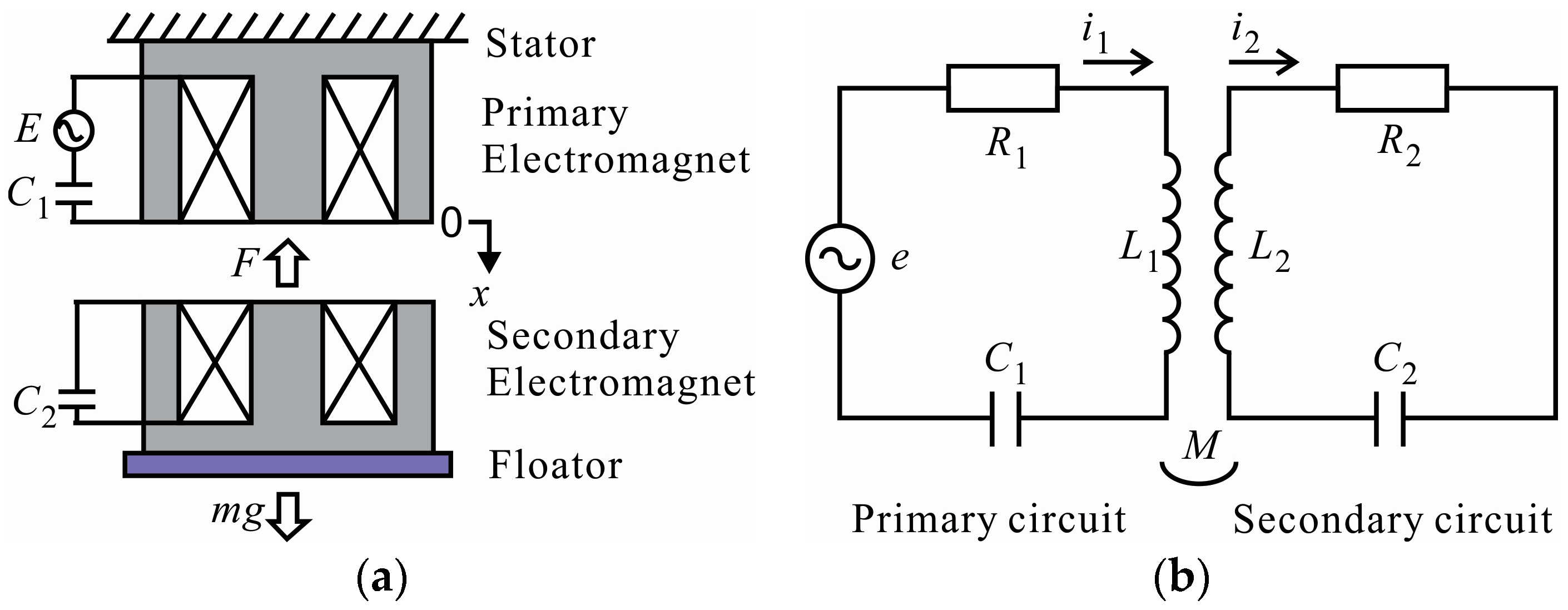
2. Principle of Magnetic Resonant Coupling

A basic model of AC magnetic suspension is shown in Figure 1a. The electromagnets face each other with a variable gap x, the electromagnet on the upper side is the primary electromagnet, and the lower side is the secondary electromagnet. The primary electromagnet is fixed with a stator, and the secondary electromagnet is fixed on the floator. Attractive force F and gravity mg act on the secondary electromagnet with the floator. The floator with a mass of m is assumed to move translationally only in the vertical direction.
The primary electromagnet forms a primary circuit with an electromagnet coil, supply power source E, and a capacitor C1 in series connection, as shown in Figure 1b. The secondary electromagnet forms a secondary circuit with an electromagnet coil and a capacitor C2 in series connection. The primary current i1 flows in the primary coil and the secondary current i2 flows in the secondary coil, where R1 and R2 are the resistance of each coil, respectively. The self-inductance of the primary coil L1, the secondary coil L2 and mutual inductance M are functions of the gap. A constant AC voltage is supplied to the primary circuit, and voltage is induced in the secondary circuit by magnetic coupling between the primary and secondary circuits. The attractive force between two electromagnets can balance the gravitational force at the equilibrium position. Circuit parameters influence to achieve a stable floating condition. Next, the magnetic circuit analyzes to find out the relation of these parameters with the gap for the stable magnetic suspension.

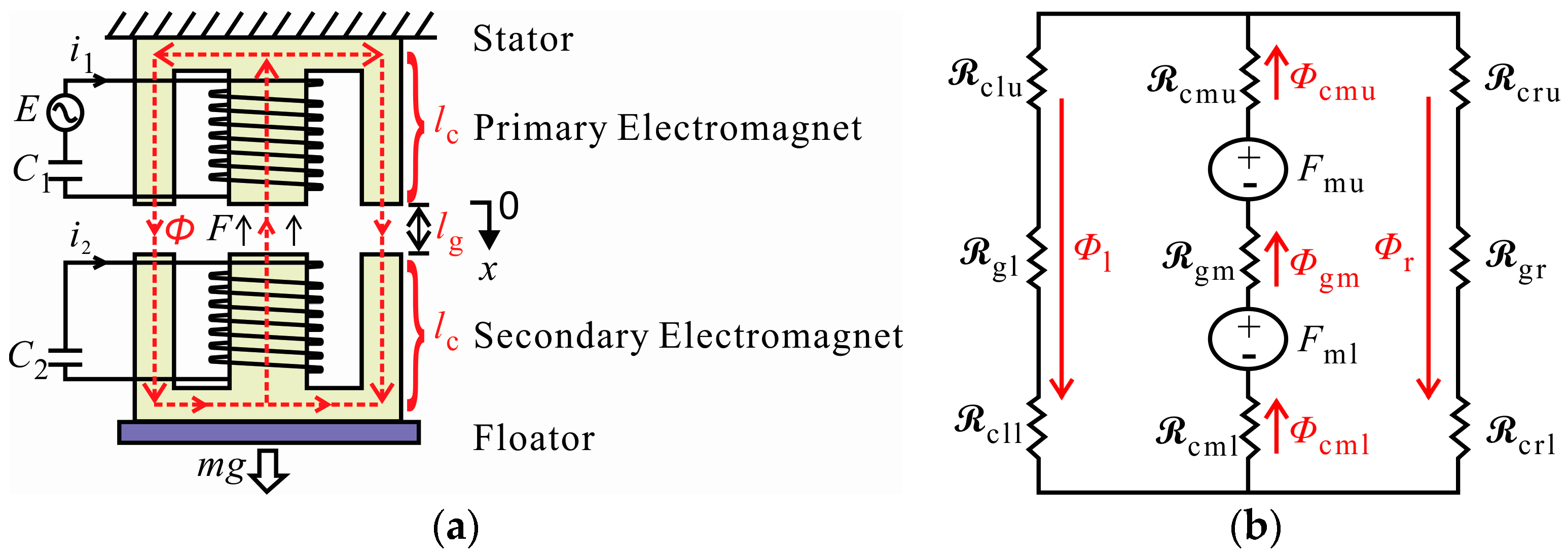
3. Analysis of Magnetic Circuit

3.1. Assumptions

1. Leakage flux
Basically, the magnetic flux produced by the MMF (magnetomotive force) is confined to the core. Some flux lines complete their paths mainly through the air, as depicted in Figure 2. Since the reluctance of air is much higher compared to the reluctance of the core, the leakage flux produced is rather small. In our analysis here, we have neglected leakage flux and assumed all the flux produced are confined to the core only.
2. Fringing effect
An air gap is present in the schematic diagram, as shown in Figure 2. These flux lines cross the air gap from the one surface of the core to another surface of the core. Thus, all the flux lines are vertical and confined to the core face area alone. Some lines of force reach the bottom surface via bulged out curved paths outside the face area of the core. These fluxes that follow curved paths are called fringing flux, and the phenomenon is called the fringing effect. We have neglected the fringing effect in our following analysis.
3. Losses
Two types of losses exist in magnetic structures: core losses and copper losses. The core losses are attributed to both hysteresis losses and eddy current losses. The copper losses exist in the winding coils due to the current conduction. To reduce the losses, we have used laminated silicon steel plates and neglected the effect of losses in the analytical solutions.

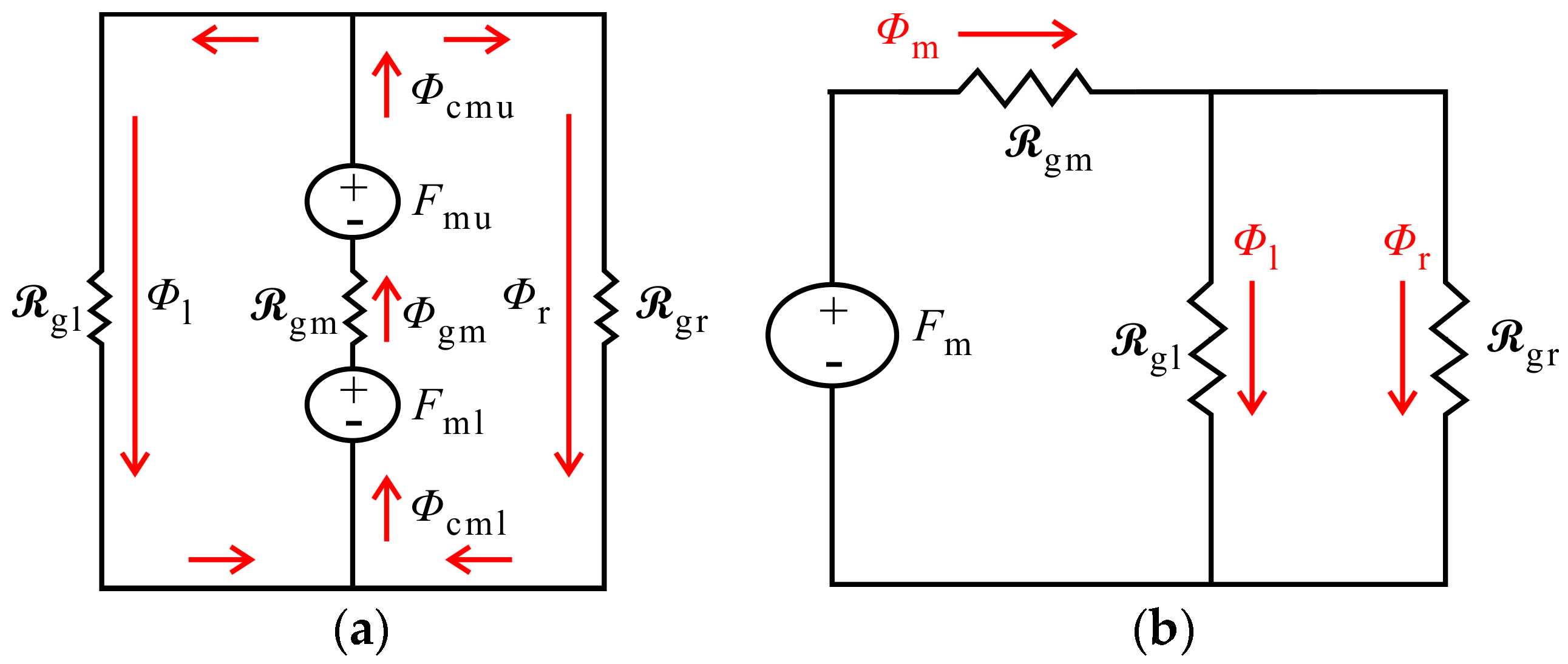
3.2. Equivalent Magnetic Circuit Analysis

Magnetic circuit modeling is important for the optimal sizing of an electrical actuator for magnetic suspension. An equivalent magnetic circuit is also used to model the electromagnetic linear actuators [35]. The leakage flux in a multi-winding transformer is modeled in [36] for different types of transformers and different air gaps between the core and the winding, where an equivalent magnetic circuit model is also used. Figure 3a shows a basic model of the magnetic circuit, which is inspired by the transformer where two coil windings are coupled to each other with a gap. The upper winding is called the primary electromagnet, and the lower winding is called the secondary electromagnet. The only middle leg of the core is surrounded by the coil of copper wire, having a diameter of 0.8 mm. The laminated silicon steel plates are stacked to make the core having a length of 34 mm where the width of the middle leg is 15 mm, and each side leg is 7.5 mm. Silicon steel plate is used because of low cost, low core loss, and high permeability at high flux densities (1.0 to 1.5 T). In the presence of alternating current (AC) in the coil, magnetic flux Φ is produced within the core according to the direction of the right-hand rule. The mean length of the flux line in the core is labeled by l c and in the air gap is labeled by l g . The strength of the flux depends on the product of the number of turns N of the coil and the current i. The quantity Ni is called MMF (magnetomotive force) and can be thought of as the cause to produce an effect in the form of flux Φ within the core.
The reluctance of a material to the setting up of magnetic flux lines in the material is determined by the following Equation (1):
= l μ 0 μ r A = l μ A
where is the reluctance, l is the mean length of the magnetic path, A is the cross-sectional area, μ 0 is the permeability of vacuum equal to 4 π × 10 7 , μ r is the relative magnetic permeability of the material (dimensionless), μ is the permeability of the material ( μ = μ 0 μ r ). Figure 3b shows the equivalent magnetic circuit indicating the reluctance in a different part of the model. The reluctances of the primary electromagnets are labeled by c l u (upper core left leg), c m u (upper core middle leg), c r u (upper core right leg) and the secondary electromagnets are labeled by c l l (lower core left leg), c m l (lower core middle leg), c r l (lower core right leg). The reluctance through the air gap is denoted by g l (gap through the left legs), g m (gap through the middle legs), g r (gap through the right legs). Air and vacuum have high reluctance, while easily magnetized materials such as silicon steel plate have low reluctance. The concentration of flux in low reluctance materials forms strong temporary poles. It causes mechanical forces that tend to move the materials towards regions of higher flux, so it is an attractive force (pull). For attractive force, we assume that the direction of currents in each coil is the same, so that the flux lines Φcmu (upper core middle leg), Φgm (gap through the middle legs), Φcml (lower core middle leg) are in the same direction. Therefore, we can sum up the magnetomotive force of the upper Fmu and lower Fml coil.
Figure 4a depicts the equivalent magnetic circuit neglecting the reluctance of the core. The equivalent circuit is simplified in Figure 4b as an approximate equivalent circuit where the total magnetomotive force is denoted by Fm, the magnetic flux through the middle legs are denoted by Φm, the magnetic flux through the left legs are denoted by Φl and magnetic flux through the right legs are denoted by Φr.
The total reluctance T of the circuit is mentioned in Equation (2).
T = g m + g l   | |   g r
The cross-sectional area of the gap through the left legs ( A g l ) is the same as the gap through the right legs ( A g r ) of both electromagnets core and is half of the gap through middle legs ( A g m ). Therefore, we can write an Equation (3),
T = l g μ 0 A g l
Permeance ρ can be defined as in Equation (4).
ρ = 1 T = μ 0 A g l l g
The primary coil around a core behaves like an inductor, which generates an induced emf within itself as a result of the changing magnetic field around its turns. The phenomenon in which a change in electric current in a circuit produces an induced electromotive force in the same circuit is called self-induction L 1 of the primary coil, as shown in Equation (5), where, N 1 is the turn number of the primary coil.
L 1 = N 1 2 ρ = N 1 2 μ 0 A g l l g
The two coils of the coupled circuit have the same turn number ( N 1 = N 2 ) of the coil and the air gap between them at the equilibrium position. So, the self-inductance of the secondary coil L 2 is the same as the self-inductance of the primary coil L 1 . Therefore, self-inductance is denoted by L where L = L 1 = L 2 . However, when the emf is induced into an adjacent secondary coil situated within the same magnetic field, the emf is said to be induced magnetically, inductively, or by mutual induction. The mutual inductance, M 12 of the secondary coil that exists with respect to primary coil and M 21 of primary coil that exists with respect to secondary coil depends on their gap with respect to each other. This gap factor is called the coupling coefficient α (alpha) which is unitless. The mutual inductances also remain the same ( M = M 12 = M 21 ), as mentioned in Equation (6). From Equations (5) and (6), it is clear that the self-inductance and the mutual inductance of these couple circuits are the functions of the gap.
M = α L 1 L 2 = α   L
From Equation (6), we get the coupling coefficient
α = M L

4. Analysis of Electrical Circuit

Since this system can be regarded as a contactless power supply system using magnetic field resonance coupling, it can be represented by a T type equivalent circuit, as shown in Figure 5. According to the dot convention, the primary and secondary coil currents enter the dot, and these two inductors behave as aiding each other.

4.1. Current Equations

Already it has shown that self-inductance, and mutual inductance of each coil is the same ( L 1 = L 2 ) and ( M 21 = M 12 = M ), respectively. After applying Kirchhoff’s Voltage Law (KVL) to the T type equivalent circuit, the equation is as follows,
R 1 i 1 ( t ) + ( L 1 M ) d i 1 ( t ) d t + M d i 0 ( t ) d t + 1 C 1 i 1 ( t ) d t = E s i n ( ω t )
R 2 i 2 ( t ) + ( L 2 M ) d i 2 ( t ) d t + M d i 0 ( t ) d t + 1 C 2 i 2 ( t ) d t = 0
It is assumed, for equation simplicity, that the coil resistance of both coils is the same ( R 1 = R 2 = R ) as well as capacitance ( C 1 = C 2 = C ). Here current i 0 ( t ) = i 1 ( t ) + i 2 ( t ) . It has been found in the real system that the primary and secondary coil currents of Equations (8) and (9) is a suppressed amplitude modulation signal in the form of Equations (10) and (11)
i 1 ( t ) = A 1 s i n ( ω t ) + B 1 c o s ( ω t )
i 2 ( t ) = A 2 s i n ( ω t ) + B 2 c o s ( ω t )
A and B in Equations (10) and (11) are functions of the gap, A 1 = A 1 ( x , t ) , A 2 = A 2 ( x , t ) , B 1 = B 1 ( x , t ) and B 2 = B 2 ( x , t ) . Substituting Equations (10) and (11) into Equations (8) and (9) and comparing the coefficients of s i n ( ω t ) and c o s ( ω t ) separately, the amplitude of the primary and the secondary current equations can be found in Equations (12) and (13). The phase of the primary coil current and secondary coil current is assumed as the same.
i 1 ^ = A 1 2 + B 1 2
i 2 ^ = A 2 2 + B 2 2

4.2. Force Equations

Force is represented by the differential of magnetic energy. During the motion of the floator, flux remains constant, but permeance changes as gap changes. So, the total MMF (magnetomotive force) also changes. Attracting force F acting on the secondary electromagnet near the equilibrium position is determined by Roters (1941) [37] in Equation (14). Assuming that this force equation is used only when the primary and secondary currents are in phase.
F = 1 2 ( i 1 ^ + i 2 ^ ) 2 L x
To calculate attractive force F, L x should be known. The functional relation between inductance and the gap x can be determined by Equation (5) and experimentally. Compared to the source frequency f, the motion of the floator is relatively slow, so only the low-frequency components of attractive force are essential to the movement of the floator. So high frequency and nonlinear items are neglected in analytical analysis.

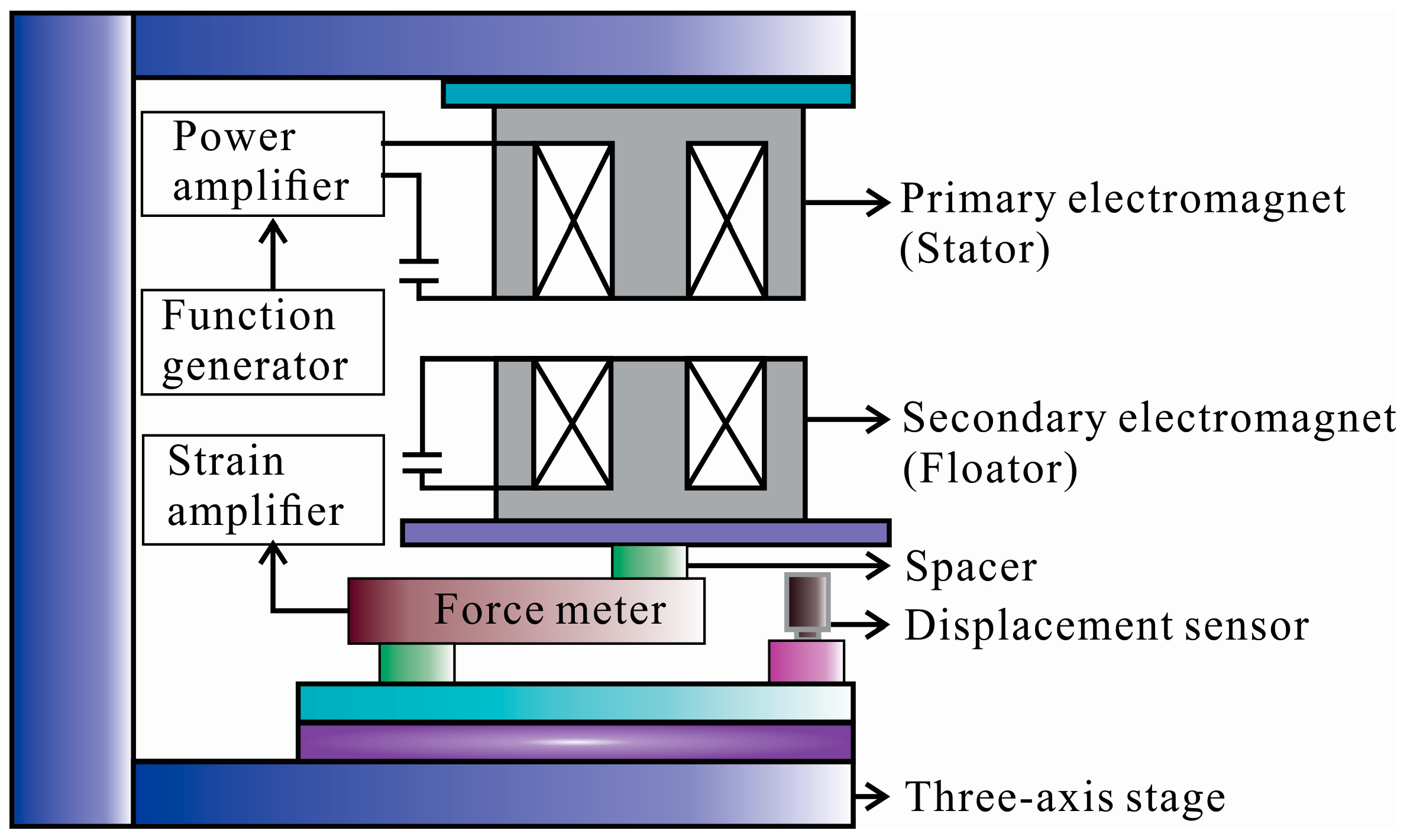
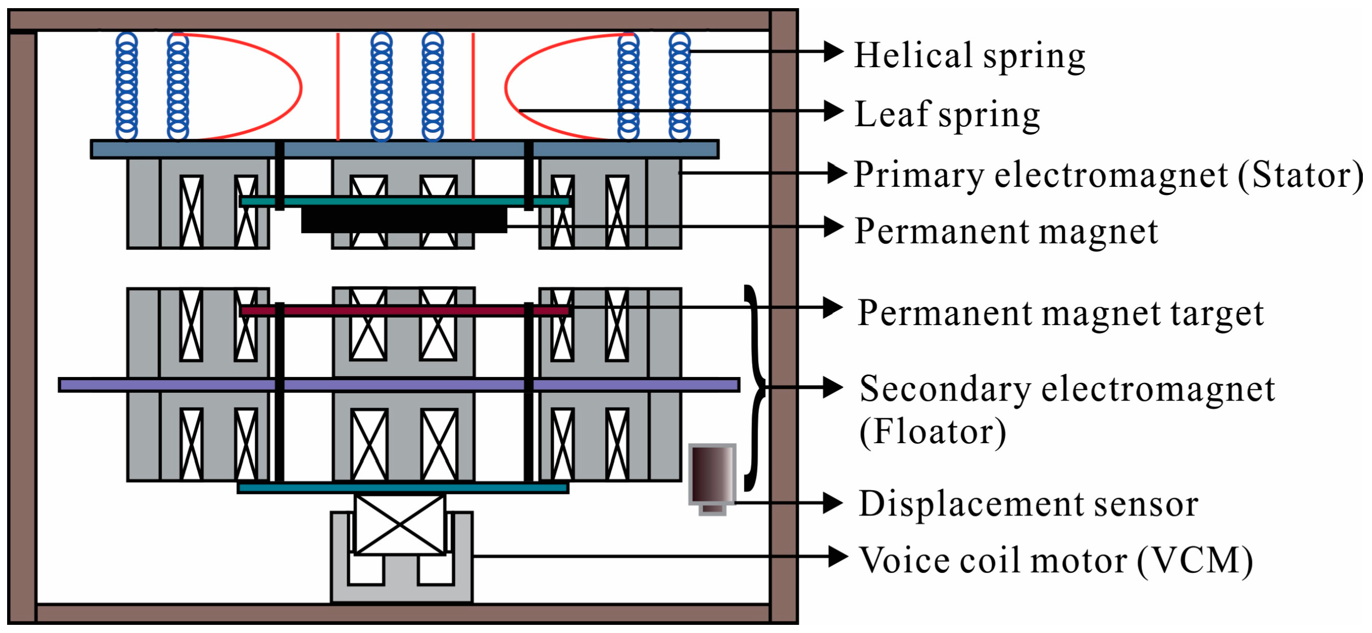
5. Experimental System

Several experiments are carried out to investigate the fundamental characteristics of the apparatus, as shown in Figure 6. Two electromagnets are faced with each other with a gap that can be varied using a three-axis stage. The primary electromagnet is fixed with the base that is considered as a stator. The secondary electromagnet is placed on the floator that is considered as a floator. A function generator is used to supply the AC voltage to the primary electromagnet through a power amplifier. The force is measured by installing a cantilever type force meter using strain gauges under the floator, which is connected to the strain amplifier. The current of each coil is measured by the current probe, and the displacement sensor is used to maintain the gap for measurement.
An experimental apparatus used for investigating suspension characteristics to achieve self-stabilization is shown in Figure 7. It is very difficult to suspend one secondary electromagnet (floator) by one primary electromagnet (stator) due to the tilting motions. So, three primary electromagnets with the same configuration are placed on a circular plate as a stator, as shown in Figure 7. Three secondary electromagnets with the same configuration are placed on both top and down of a circular plate as floators. A permanent magnet is incorporated into the stator plate to reduce the power supply to the primary electromagnets by adding an extra attractive upward force to the floator. To confirm the self-stabilization of the suspension, an external sinusoidal disturbance force is made to act on the floator in the direction of the gravity force using a voice coil motor (VCM). A displacement sensor is used to measure the displacement of the floator. The stator is overhung by helical spring to suspend the stator flexibly in the vertical direction. A leaf spring is used to contain the single-degree-of-freedom of the oscillation laterally.

6. Investigation of Fundamental Characteristics

All calculations are performed in Wolfram Mathematica 11.3 for analytical analysis and numerical simulations based on the equivalent circuit equations of the proposed model. To confirm the theoretical analysis, we carried out an experimental verification using two electromagnets facing each other with a gap, as shown in Figure 6. The value of circuit parameters in both theoretical and experimental analysis are considered as the same. The circuit constant such as the capacitance C of each coil is 2.2 µF, coil resistance R of both coils is 2.5 Ω The characteristics of the self-inductance, mutual inductance, currents, force, and stiffness are investigated analytically and experimentally.

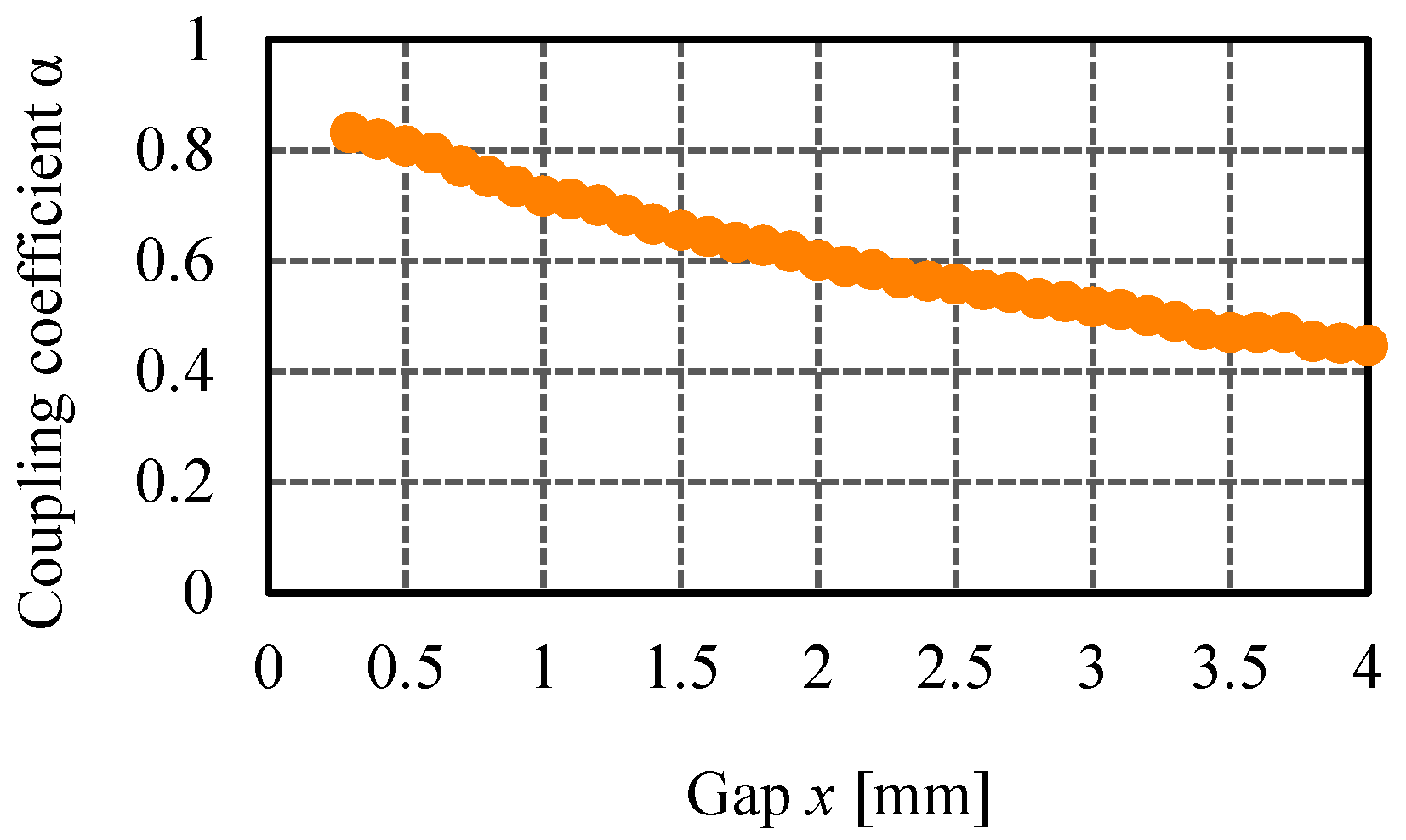
6.1. Characteristics of Self-Inductance and Mutual Inductance

The self-inductance L and the mutual inductance M are measured experimentally. The self-inductance of the primary coil is measured while the secondary coil circuit is open or vice-versa. The mutual inductance is measured while both the coil circuits are closed. Figure 8a depicts the comparison between theoretical and experimental results of the self-inductance. Theoretical self-inductance is calculated from static numerical analysis using Equation (5) where N 1 = 220 turns, A g l = 7.5 × 34 mm2, l g is from 0 to 4 mm. The actual cross-sectional area of flux density in the air gap A g is higher than the cross-sectional area in the core A c due to the fringing effect. This also dynamically changes with the change of the gap x. We avoided this fringing effect in numerical analysis. Also, there is some machining error to measure the gap while experiments are conducted. The theoretical and experimental characteristics of the self-inductance L show that the inductance decreases with the increasing of the gap x.
Figure 8b shows the comparison between the theoretical and experimental results of the mutual inductance M . The theoretical mutual inductance is calculated from the static numerical analysis using Equation (6) where α is the measured value, L is the theoretical value for 0 < x 4 mm. It is difficult to estimate the accurate coupling coefficient α analytically. The measured coupling coefficient α is calculated using Equation (7) where the measured values of the self-inductance L and the mutual inductance M are considered. Figure 9 illustrates the characteristics of the coupling coefficient α to the gap x. The theoretical and experimental characteristics show that the mutual inductance M decreases with the increasing of the gap x. To calculate the currents and force using the measured value of self-inductance, mutual inductance, and coupling coefficient, we have made a functional relationship of self-inductance L , mutual inductance M , and coupling coefficient α with the gap of x m by applying a curve fitting function as mentioned in Equations (15)–(17), respectively.
L = 5 × 10 4 × x 0.582       [ H ]
M = 6 × 10 5 × x 0.849     [ H ]
α = 103.07 × x + 0.8275

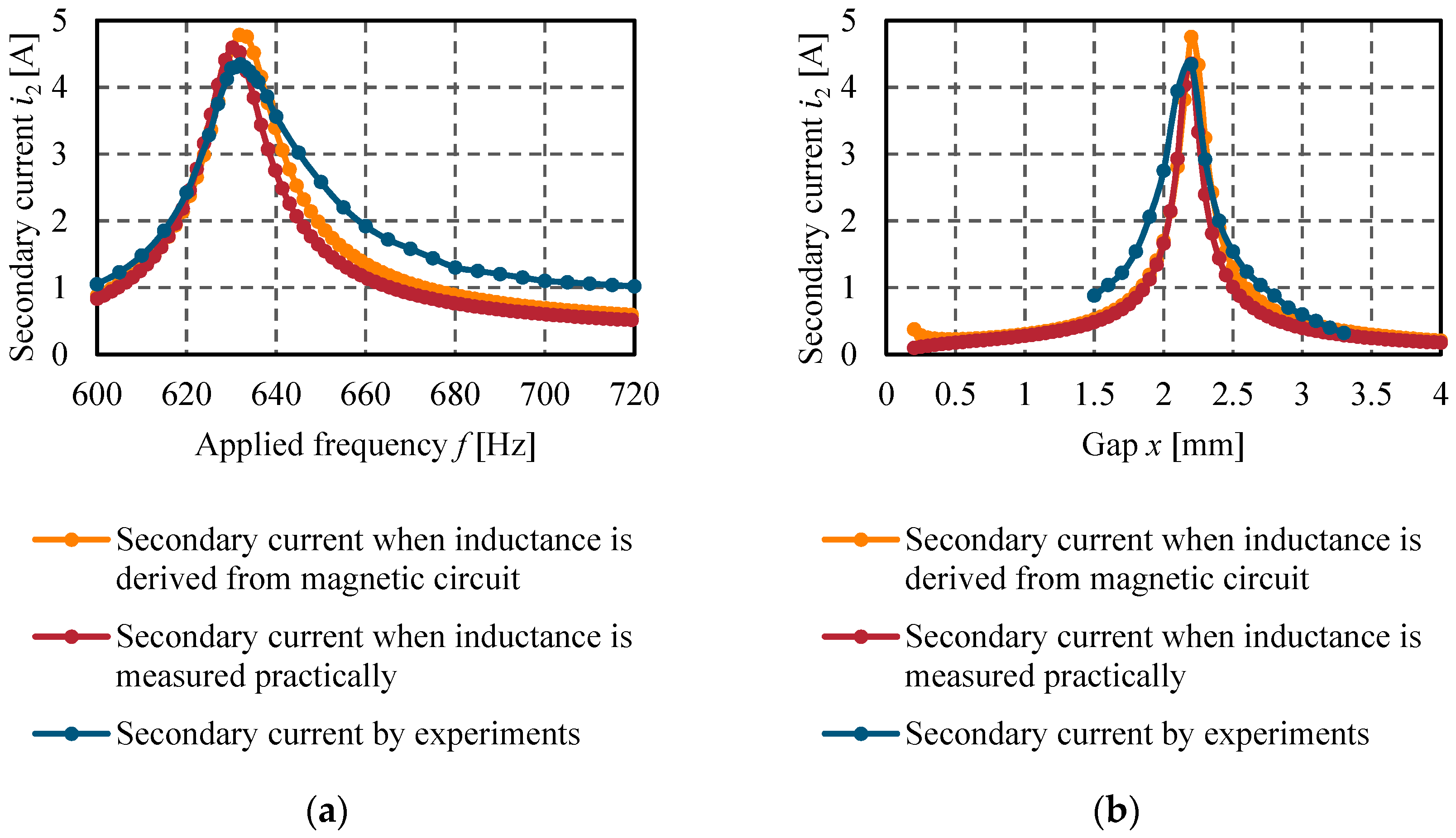
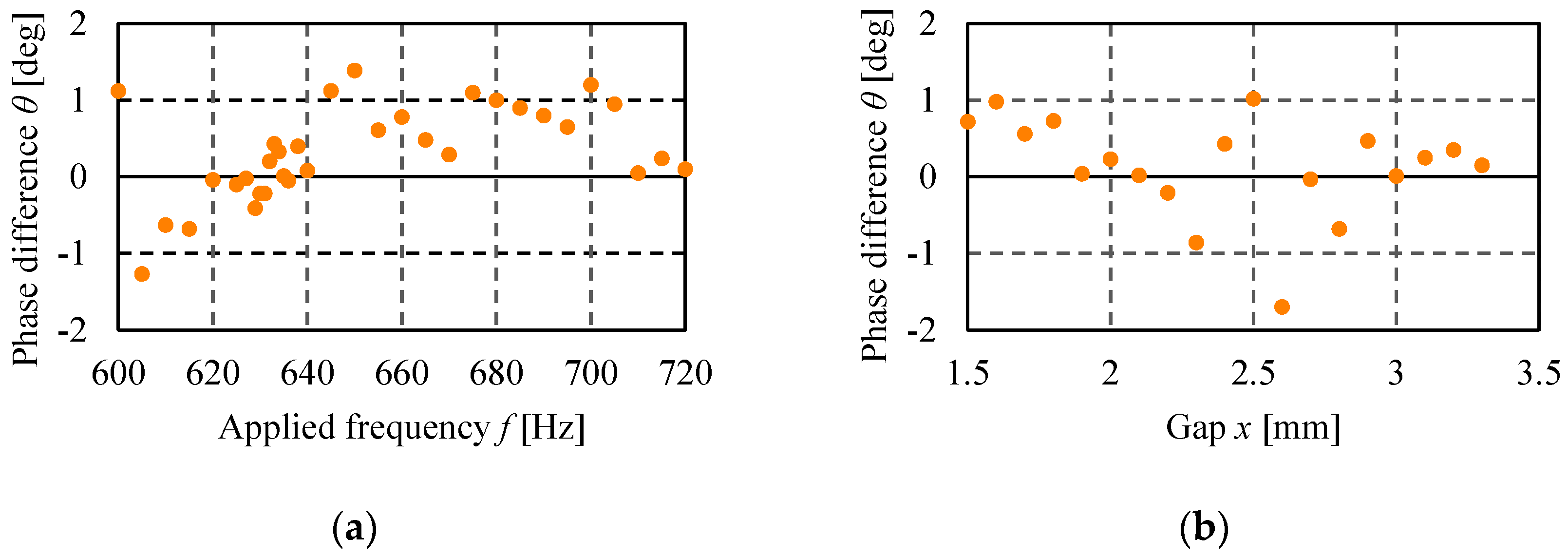
6.2. Characteristics of Currents

The primary current i 1 has been estimated depending on the variable applied frequency f and the variable gap x between the primary and secondary electromagnets, as shown in Figure 10a. The primary current i 1 increases as the applied frequency f, and the gap x increases up to the resonance frequency f 0 of 632 Hz. This characteristic is an advantage for achieving self-stabilization. When the floator electromagnet approaches the stator electromagnet, both currents i 1 and i 2 decreases, and when the floator departs from the stator electromagnet, both currents i 1 and i 2 increases. The peak value of both the currents are observed at the resonance frequency f 0 of 632 Hz. The amplitude of the primary current i 1 is estimated using Equation (12) in two ways where the self-inductance L and mutual inductance M has derived analytically from the magnetic circuit by using the Equations (5) and (6), and both inductances are estimated from the Equations (15) and (16) practically. These two results are compared with the experimental results in Figure 10a when the gap x is 2.0 mm, and in Figure 10b when the applied frequency f is 650 Hz. Experimentally it is difficult to measure the primary current i 1 below the applied frequency f of 600 Hz and 1.5 mm gap, as shown in Figure 10a,b, respectively, but analytically it is possible to estimate in a wide range. The differences are observed due to some assumptions that have been taken into consideration in analytical solutions. However, this comparison shows a good agreement between the analytical and experimental measurements. More accurate results may be found after optimizing the circuit and physical parameters.
Figure 11 shows the characteristics of the secondary current i 2 , which is also estimated in the same way as mentioned in the primary current. With the same principle and process, we calculated the amplitude of the secondary current i 2 using Equation (13). The analytical results are compared with the experimental results in Figure 11a when the gap x is 2.0 mm, and in Figure 11b when the applied frequency f is 650 Hz. It is observed that the primary and secondary electromagnets have almost the same peak level at the same resonance frequency f 0 of 632 Hz and the gap x of 2.2 mm, which is a suitable characteristic for efficient wireless power transfer. Moreover, it is proved that the self-inductance in each coil remains the same because currents and turn number of coils are same.
Figure 12 illustrates the characteristics of the phase difference θ between the primary current i 1 and secondary current i 2 . The phase difference θ is measured experimentally. Figure 12a shows the phase difference when the gap x is 2.0 mm, and Figure 12b shows the phase difference when the applied frequency f is 650 Hz. Experimental results satisfy the assumption that was considered in the theoretical analysis as the phase difference θ is virtually zero.

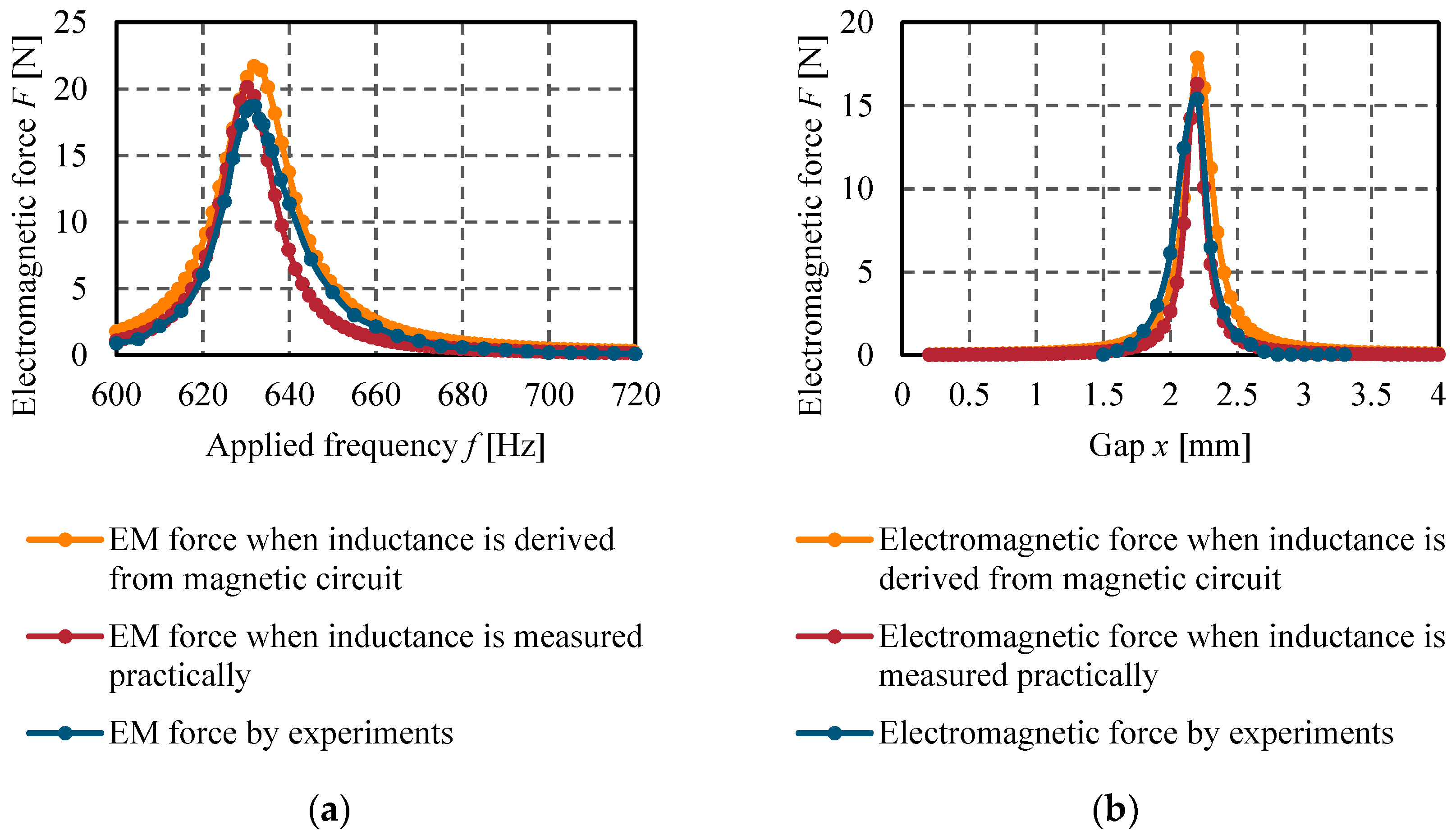
6.3. Characteristics of Attractive Force

The electromagnetic attractive force F is estimated using Equation (14) numerically. The force depends on the currents and inductance, whereas the inductance depends on the gap between the primary and secondary electromagnets. So here also, the inductance is derived by using Equations (5) and (6) from the magnetic circuit and calculated by using Equations (15) and (16) practically. The electromagnetic attractive force F is measured by the experiment also, as shown in Figure 6. Figure 13a illustrates the electromagnetic attractive force F when the applied frequency f increases at the gap x of 2.0 mm. Usually, the maximum attractive force is generated when both circuits resonate at the same time. So, the maximum attractive force of almost 20 N is observed at a resonant frequency f 0 of 632 Hz. Figure 13b shows the electromagnetic attractive force F when the gap x increases at the applied frequency f of 650 Hz. Here, the maximum attractive force is observed as both circuits resonate at the gap of 2.2 mm. The characteristics indicate that force increases as the gap increases. Such characteristics are referred to as positive stiffness, which is shown later. So, we can expect the possibility of self-stabilization.

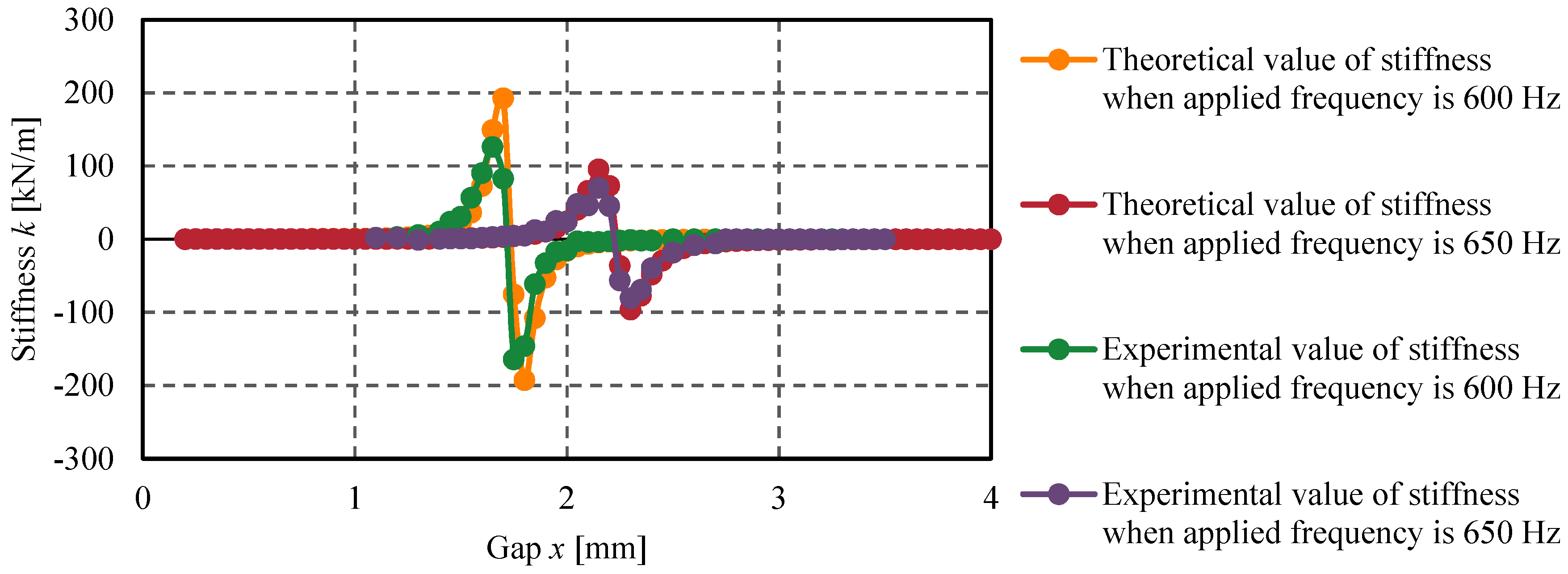
6.4. Characteristics of Stiffness

It is proved that resonance frequency f 0 changes with the gap x and the applied frequency f accordingly, as shown in Figure 14. The essential characteristic of self-stabilization is the stiffness k, which is shown in Figure 15. The value of stiffness k is estimated from measured force-gap characteristics by k = Δ F / Δ x from Figure 14. It indicates that the stiffness is a nonlinear function of the gap, which is a property similar to the coupling coefficient in an energy harvesting system [38]. The stiffness increases when the gap increases within 0 < x 1.7 mm. Such characteristic is called positive stiffness, which enables the floator to levitate without using any controller. Positive stiffness lies in 0 < x 1.7 mm when the applied frequency f is 600 Hz and 0 < x 2.15 mm when the applied frequency f is 650 Hz. It is found that the region of the gap with positive stiffness tends to be wider, and the gap with maximum stiffness becomes lower as the applied frequency increases. The behavior of the stiffness k changes with the variable applied frequency f. These results demonstrate that the stiffness of suspension can be adjusted by changing the gap and the applied frequency. The comparison between theoretical and experimental results show comparatively good agreements. So, it can be said that self-stabilization is possible in the range of positive stiffness region.

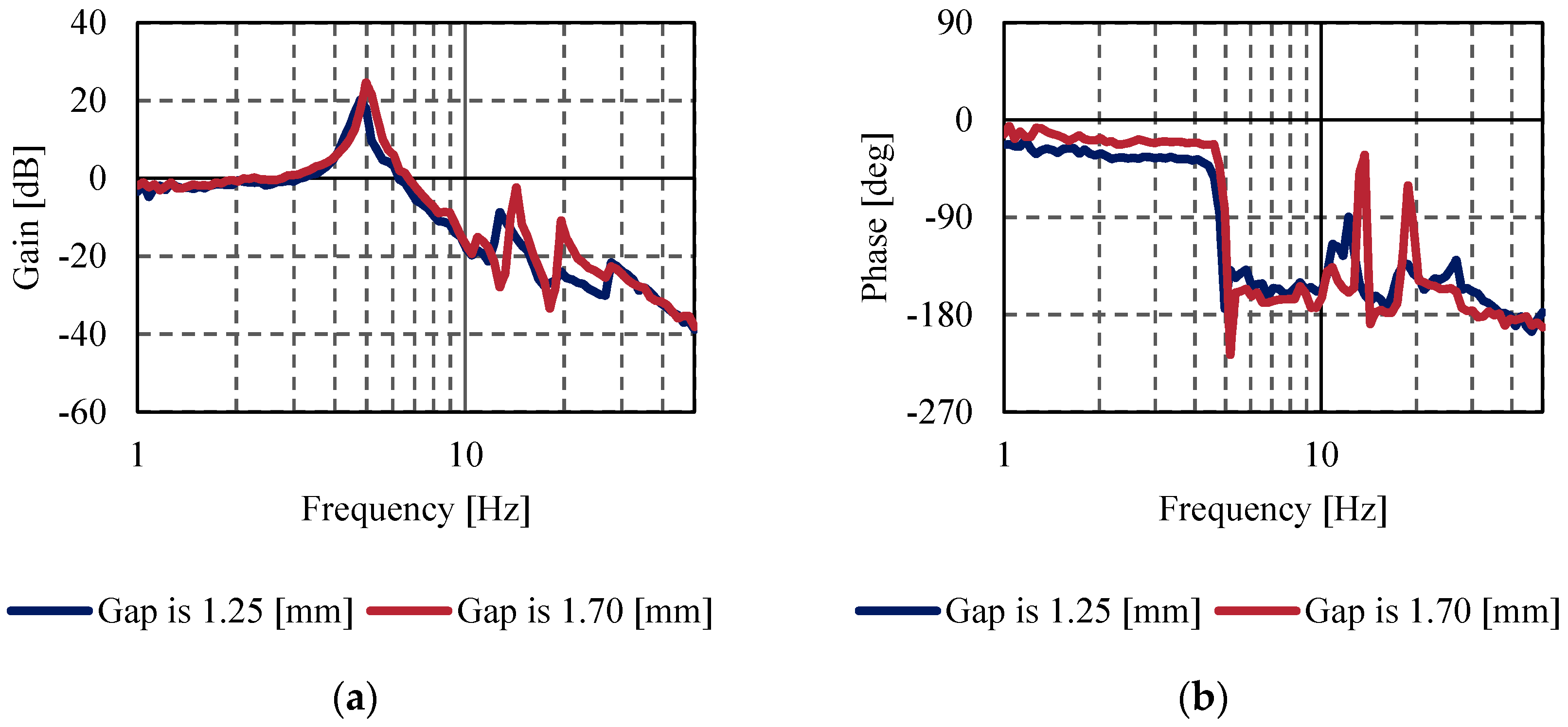
7. Characteristics of Suspension

By incorporating the permanent magnet into the stator plate, as shown in Figure 7, the total upward attractive force increases. The supply voltage was 52 V, the current was 5 A without permanent magnet. However, the supply voltage was 46 V and the current was 0.45 A with permanent magnets. The estimated phase difference was 35 deg. The calculated supply power was 212.97 W without permanent magnet and 16.96 W with permanent magnets. Thus, the supply power was reduced to approximately 92% using the permanent magnet to the upper stator. External sinusoidal disturbance force was applied to the floator to investigate the self-stabilization during the suspension, as shown in Figure 7. The amplitude of the disturbance force was 0.23 N and the frequency range was 1 to 50 Hz. The experimental result of the frequency response is shown in Figure 16. The floator is levitated in stable conditions with a gap x of 1.25 mm and 1.70 mm for the applied frequency of 600 Hz and 650 Hz, respectively. The mechanical resonance frequency f r is observed at 4.78 Hz for the gap x of 1.25 mm and 4.97 Hz for the gap x of 1.70 mm. The calculated stiffness k is 4.10 kN/m and 3.77 kN/m for the corresponding gap x, respectively. These calculated stiffnesses lie in the region of 0 < x 1.7 mm and 0 < x 2.15 mm of positive stiffness of Figure 15, respectively. It proves that the stability is kept even in the presence of disturbance acting on the floator. It can be said that self-stabilization is achieved. The floator is levitated without using any active control in the region of positive stiffness. The point to be noted is that the stator is suspended by a mechanical spring, which generates damping effects of 0.023 Ns/m.

8. Conclusions

The fundamental characteristics of AC magnetic suspension using magnetic resonant coupling were studied analytically and experimentally. An equivalent magnetic circuit was derived for investigating the characteristics of the inductances of the coupled coils with the gap. The force and current equations were derived from an equivalent electrical circuit. The analytical analysis predicted the feasibility of magnetic resonant coupling, which was validated experimentally. The assumption of the phase difference between the primary and secondary current in the theoretical analysis was verified experimentally. The coupling coefficient was measured experimentally and used in the numerical calculation. The experimental and analytical results of the fundamental characteristics showed that the currents, force, and stiffness are adjustable by selecting the applied frequency of the AC voltage source. It was predicted from the fundamental characteristics that the suspension system has the self-stabilization characteristic. The measured frequency responses of the suspension to disturbance supported this prediction. The floator was kept at stable conditions during the levitation, even in the presence of disturbance. It can be said from these characteristics that the floator can be levitated without any control and applied damper in the region of positive stiffness. The supply power was reduced up to 92% by using permanent magnets to the stator plate. Based on this information, further research can be expanded to make any devices using magnetic resonant coupling. The fringing effect at a large gap in the magnetic circuit can be considered for more accuracy. Although there are some differences between analytical and experimental results due to the assumptions and losses, the comparison results show a promising correlation.

Author Contributions

A.R. and T.M. wrote the paper, M.T. contributed to the fabrication of the electric circuits, Y.I. contributed in designing the experimental device, A.R. conducted the experiments, T.M. supervised the experiments. All authors have read and agreed to the published version of the manuscript.

Funding

This research is supported by Adaptable and Seamless Technology transfer Program through Target-driven R&D (A-STEP) from Japan Science and Technology Agency (JST), grant number JPMJTM19B3.

Conflicts of Interest

The authors declare no conflict of interest. The funding sponsors had no role in the design of the study, in the collection, analyses, or interpretation of data, in writing of the manuscript, and in the decision to publish the results.

References

  1. Britcher, C.; Britcher, C. Application of magnetic suspension technology to large scale facilities–Progress, problems and promises. In Proceedings of the 35th Aerospace Sciences Meeting and Exhibit, Reno, NV, USA, 6–9 January 1997; American Institute of Aeronautics and Astronautics: Reston, VA, USA, 1997. [Google Scholar]
  2. Mushi, S.E.; Lin, Z.; Allaire, P.E. Design, Construction, and Modeling of a Flexible Rotor Active Magnetic Bearing Test Rig. IEEE/ASME Trans. Mechatron. 2012, 17, 1170–1182. [Google Scholar] [CrossRef]
  3. MIZUNO, T. Analysis on the Fundamental Properties of Active Magnetic Bearing Control Systems by a Transfer Function Approach. JSME Int. J. Ser. C 2001, 44, 367–373. [Google Scholar] [CrossRef] [Green Version]
  4. Kimman, M.H.; Langen, H.H.; Munnig Schmidt, R.H. A miniature milling spindle with Active Magnetic Bearings. Mechatronics 2010, 20, 224–235. [Google Scholar] [CrossRef]
  5. Ahrens, M.; Kucera, L.; Larsonneur, R. Performance of a magnetically suspended flywheel energy storage device. IEEE Trans. Control. Syst. Technol. 1996, 4, 494–502. [Google Scholar] [CrossRef]
  6. Hijikata, W.; Shinshi, T.; Asama, J.; Li, L.; Hoshi, H.; Takatani, S.; Shimokohbe, A. A Magnetically Levitated Centrifugal Blood Pump With a Simple-structured Disposable Pump Head. Artif. Organs 2008, 32, 531–540. [Google Scholar] [CrossRef] [PubMed]
  7. Jayawant, B.V. Review Lecture–Electromagnetic suspension and levitation techniques. Proc. R. Soc. Lond. A. Math. Phys. Sci. 1988, 416, 245–320. [Google Scholar]
  8. Eisaka, T.; Hanajima, N.; Yanagita, Y.; Tagawa, R. Control of a Magnetic Levitation System by Robust Model Matching. IFAC Proc. Vol. 1993, 26, 173–176. [Google Scholar] [CrossRef]
  9. Yadav, S.; Verma, S.K.; Nagar, S.K. Optimized PID controller for magnetic levitation system. Ifac-PapersOnLine 2016, 49, 778–782. [Google Scholar] [CrossRef]
  10. Golob, M.; Tovornik, B. Modeling and control of the magnetic suspension system. ISA Trans. 2003, 42, 89–100. [Google Scholar] [CrossRef]
  11. Atherton, D. Maglev using permanent magnets. IEEE Trans. Magn. 1980, 16, 146–148. [Google Scholar] [CrossRef]
  12. Bassani, R. Earnshaw (1805–1888) and Passive Magnetic Levitation. Meccanica 2006, 41, 375–389. [Google Scholar] [CrossRef]
  13. Jayawant, B.V.; Sinha, P.K.; Wheeler, A.R.; Whorlow, R.J.; Willsher, J. Development of 1-ton magnetically suspended vehicle using controlled d.c. electromagnets. Proc. Inst. Electr. Eng. 1976, 123, 941. [Google Scholar] [CrossRef]
  14. Lindon, P.; Henn, J.W. Linear perturbation models for a.c. magnetic suspension systems. Int. J. Control. 1979, 30, 427–446. [Google Scholar] [CrossRef]
  15. Henn, J.W. Linear perturbation models for a.c. magnetic suspension systems: Experimental and theoretical results. Control. Theory Appl. IEE Proc. D 1980, 127, 64–74. [Google Scholar] [CrossRef]
  16. Moriyama, S.I. AC Magnetic Suspension Using a Differential Feedback Power Amplifier. IEEJ Trans. Ind. Appl. 1998, 118, 916–921. [Google Scholar] [CrossRef] [Green Version]
  17. Kaplan, B.-Z.; Regev, D. Dynamic stabilization of tuned-circuit levitators. IEEE Trans. Magn. 1976, 12, 556–559. [Google Scholar] [CrossRef]
  18. Hagihara, S. Performance and stability of a magnetic suspension device using a tuned LCR circuit. Proc. Inst. Electr. Eng. 1978, 125, 153. [Google Scholar] [CrossRef]
  19. Kaplan, B.Z. A new analysis of tuned circuit levitators. Int. J. Non. Linear. Mech. 1974, 9, 75–87. [Google Scholar] [CrossRef]
  20. Jin, J.; Higuchi, T. Dynamics and Stability of Magnetic Suspension Systems Using Tuned LC Circuit. JSME Int. J. Ser. CDyn. Control. Robot. Des. Manuf. 1994, 37, 494–498. [Google Scholar] [CrossRef]
  21. Tsukamoto, O.; Yasuda, K.; Chen, J.Z. A new magnetic levitation system with AC magnets. IEEE Trans. Magn. 1988, 24, 1497–1500. [Google Scholar] [CrossRef]
  22. Imura, T.; Hori, Y. Maximizing Air Gap and Efficiency of Magnetic Resonant Coupling for Wireless Power Transfer Using Equivalent Circuit and Neumann Formula. IEEE Trans. Ind. Electron. 2011, 58, 4746–4752. [Google Scholar] [CrossRef]
  23. Wang, Z.; Liu, Y.; Wei, Y.; Song, Y. Study on electromagnetic characteristics of the magnetic coupling resonant coil for the wireless power transmission system. J. Appl. Biomater. Funct. Mater. 2018, 16, 140–149. [Google Scholar] [CrossRef] [PubMed] [Green Version]
  24. Barman, S.D.; Reza, A.W.; Kumar, N.; Karim, M.E.; Munir, A.B. Wireless powering by magnetic resonant coupling: Recent trends in wireless power transfer system and its applications. Renew. Sustain. Energy Rev. 2015, 51, 1525–1552. [Google Scholar] [CrossRef]
  25. Fareq, M.; Fitra, M.; Irwanto, M.; Syafruddin, H.S.; Gomesh, N.; Irwan, Y.M.; Halim, M.A.; Suwarno; Herman, A.; Hussain, T. 50 cm Air Gap Wireless Power Transfer by Magnetic Resonance Coupling. Appl. Mech. Mater. 2015, 785, 205–209. [Google Scholar] [CrossRef]
  26. Mizuno, T.; Takahashi, K.; Ishino, Y.; Takasaki, M. Novel AC magnetic suspension using magnetic resonant coupling. Mech. Eng. J. 2016, 3, 1–12. [Google Scholar] [CrossRef] [Green Version]
  27. Rahman, A.; Mizuno, T.; Ishino, Y.; Takasaki, M.; Yamaguchi, D. Performance study on newly developed AC magnetic suspension system using magnetic resonance coupling. Int. J. Appl. Electromagn. Mech. 2020. accepted. [Google Scholar]
  28. Mizuno, T.; Takahashi, K.; Ishino, Y.; Takasaki, M. Proposal of AC Magnetic Suspension Using Magnetic Resonant Coupling. In Proceedings of the 14th International Symposium on Magnetic Bearings (ISMB14), Linz, Austria, 11−14 August 2014; pp. 491–494. [Google Scholar]
  29. Akiyama, T.; Mizuno, T.; Takasaki, M.; Ishino, Y.; Obara, K. Development of a totally active magnetically suspended gyro. Mechatronics 2014, 24, 1059–1070. [Google Scholar] [CrossRef]
  30. Cassell, W.L. Determining the equivalent circuit of a transformer by matrix methods. Electr. Eng. 1957, 76, 913–915. [Google Scholar] [CrossRef]
  31. Lord, H.W. An equivalent circuit for transformers in which nonlinear effects are present. Trans. Am. Inst. Electr. Eng. Part. I Commun. Electron. 1959, 78, 580–586. [Google Scholar] [CrossRef]
  32. Bhowmick, D.; Manna, M.; Chowdhury, S.K. Estimation of Equivalent Circuit Parameters of Transformer and Induction Motor from Load Data. IEEE Trans. Ind. Appl. 2018, 54, 2784–2791. [Google Scholar] [CrossRef]
  33. Guillod, T.; Krismer, F.; Kolar, J.W. Magnetic equivalent circuit of MF transformers: Modeling and parameter uncertainties. Electr. Eng. 2018, 100, 2261–2275. [Google Scholar] [CrossRef]
  34. Radun, A.V. Development of Dynamic Magnetic Circuit Models Including Iron Saturation and Losses. IEEE Trans. Magn. 2014, 50, 1–10. [Google Scholar] [CrossRef]
  35. Han, D.K.; Chang, J.H. Design of Electromagnetic Linear Actuator Using the Equivalent Magnetic Circuit Method. IEEE Trans. Magn. 2016, 52, 1–4. [Google Scholar] [CrossRef]
  36. Luo, M.; Dujic, D.; Allmeling, J. Leakage flux modelling of multi-winding transformer using permeance magnetic circuit. In Proceedings of the 2016 IEEE Applied Power Electronics Conference and Exposition (APEC), Long Beach, CA, USA, 20–24 March 2016; IEEE: Los Alamitos, CA, USA, 2016; pp. 1108–1114. [Google Scholar]
  37. Roters, H.C. Electromagnetic Devices, 1st ed.; John Wiley & Sons, Inc.: Hoboken, NJ, USA, 1941. [Google Scholar]
  38. Kecik, K.; Mitura, A.; Lenci, S.; Warminski, J. Energy harvesting from a magnetic levitation system. Int. J. Non. Linear. Mech. 2017, 94, 200–206. [Google Scholar] [CrossRef]
Figure 1. Schematic diagram of AC magnetic suspension using magnetic resonant coupling: (a) basic model of magnetic suspension; (b) equivalent circuit of the basic model.
Actuators 09 00052 g001
Figure 2. Schematic diagram of the basic model showing the flow of flux through the core and air gap.
Actuators 09 00052 g002
Figure 3. Schematic diagram of magnetic circuit: (a) basic model of the magnetic circuit; (b) equivalent magnetic circuit of the basic model.
Actuators 09 00052 g003
Figure 4. The reluctance of core material is neglected and redrawn the equivalent magnetic circuit: (a) equivalent magnetic circuit avoiding reluctance of the core material; (b) approximate equivalent magnetic circuit of the basic model.
Actuators 09 00052 g004
Figure 5. T type equivalent circuit of the magnetically coupled primary and secondary circuit.
Actuators 09 00052 g005
Figure 6. Schematic diagram of the experimental apparatus for investigating fundamental characteristics.
Actuators 09 00052 g006
Figure 7. Schematic diagram of the experimental apparatus for investigating self-stabilization during the suspension.
Actuators 09 00052 g007
Figure 8. Comparison of characteristics curve between experimental and theoretical value: (a) self-inductance; (b) mutual inductance.
Actuators 09 00052 g008
Figure 9. The measured value of the coupling coefficient α to the gap x.
Actuators 09 00052 g009
Figure 10. The comparison of the characteristics curve of the primary current: (a) when the gap x is 2.0 mm; (b) when the applied frequency f is 650 Hz.
Actuators 09 00052 g010
Figure 11. The comparison of the characteristics curve of the secondary current: (a) when the gap x is 2.0 mm; (b) when the applied frequency f is 650 Hz.
Actuators 09 00052 g011
Figure 12. Characteristics of the phase difference between the primary and secondary currents: (a) when the gap x is 2.0 mm; (b) when the applied frequency is 650 Hz.
Actuators 09 00052 g012
Figure 13. The comparison of the characteristics curve of electromagnetic attractive force: (a) when the gap x is 2.0 mm; (b) when the applied frequency f is 650 Hz.
Actuators 09 00052 g013
Figure 14. The comparison of the characteristics curve of electromagnetic attractive force when the applied frequency f is 600 Hz and 650 Hz.
Actuators 09 00052 g014
Figure 15. The comparison of the characteristics curve of stiffness when the applied frequency is 600 Hz and 650 Hz.
Actuators 09 00052 g015
Figure 16. The frequency responses of the suspension to disturbance to the floator when the gap x is 1.25 mm and 1.70 mm: (a) gain diagram; (b) phase diagram.
Actuators 09 00052 g016

