The Design, Kinematics and Torque Analysis of the Self-Bending Soft Contraction Actuator


Abstract
1. Introduction
2. The Self-Bending Contraction Actuator (SBCA)
Fabrication of the SBCA
- 1.
- Fix the SBCA from the air inlet side vertically.
- 2.
- Connect a 9-axis motion tracking (BNO055) sensor to the free end, to measure the bending angle.
- 3.
- Attach load support to adjust the load value.
- 4.
- Apply air pressure via (3/3 solenoid valve).
- 5.
- Measure the air pressure by a pressure sensor.
- 6.
- Use Arduino Mega 2560 to control the experiment process.
3. The Kinematics of the SBCA
4. The Bending Torque of the SBCA
5. Applications of the SCBA
6. Conclusions
Author Contributions
Funding
Acknowledgments
Conflicts of Interest
References
- Kelasidi, E.; Andrikopoulos, G.; Nikolakopoulos, G.; Manesis, S. A survey on pneumatic muscle actuators modeling. In Proceedings of the 2011 IEEE International Symposium on Industrial Electronics, Gdansk, Poland, 27–30 June 2011; pp. 1263–1269. [Google Scholar] [CrossRef]
- Tondu, B.; Lopez, P. Modeling and control of McKibben artificial muscle robot actuators. IEEE Control Syst. 2000, 20, 15–38. [Google Scholar] [CrossRef]
- Al-Ibadi, A.; Nefti-Meziani, S.; Davis, S. Active Soft End Effectors for Efficient Grasping and Safe Handling. IEEE Access 2018, 6, 23591–23601. [Google Scholar] [CrossRef]
- Al-Ibadi, A.; Nefti-Meziani, S.; Davis, S. Efficient structure-based models for the McKibben contraction pneumatic muscle actuator: The full description of the behaviour of the contraction PMA. Actuators 2017, 6, 32. [Google Scholar] [CrossRef]
- Chou, C.-P.; Hannaford, B. Measurement and modeling of McKibben pneumatic artificial muscles. IEEE Trans. Robot. Autom. 1996, 12, 90–102. [Google Scholar] [CrossRef]
- Godage, I.S.; Branson, D.T.; Guglielmino, E.; Caldwell, D.G. Pneumatic muscle actuated continuum arms: Modelling and experimental assessment. In Proceedings of the 2012 IEEE International Conference on Robotics and Automation, Saint Paul, MN, USA, 14–18 May 2012; pp. 4980–4985. [Google Scholar] [CrossRef]
- Takosoglu, J.E.; Laski, P.A.; Blasiak, S.; Bracha, G.; Pietrala, D. Determining the Static Characteristics of Pneumatic Muscles. Meas. Control 2016. [Google Scholar] [CrossRef]
- Davis, S.; Caldwell, D.G. Braid Effects on Contractile Range and Friction Modeling in Pneumatic Muscle Actuators. Int. J. Rob. Res. 2006, 25, 359–369. [Google Scholar] [CrossRef]
- Davis, S.; Tsagarakis, N.; Canderle, J.; Caldwell, D.G. Enhanced Modelling and Performance in Braided Pneumatic Muscle Actuators. Int. J. Rob. Res. 2003, 22, 213–227. [Google Scholar] [CrossRef]
- Szepe, T. Accurate force function approximation for pneumatic artificial muscles. In Proceedings of the LINDI 2011—3rd IEEE International Symposium on Logistics and Industrial Informatics, Budapest, Hungary, 25–27 August 2011. [Google Scholar] [CrossRef]
- Al-Ibadi, A.; Nefti-Meziani, S.; Davis, S. Design, implementation and modelling of the single and multiple extensor pneumatic muscle actuators. Syst. Sci. Control Eng. 2018, 6, 80–89. [Google Scholar] [CrossRef]
- Razif, M.R.M.; Faudzi, A.A.M.; Bavandi, M.; Nordin, I.N.A.M.; Natarajan, E.; Yaakob, O. Two chambers soft actuator realizing robotic gymnotiform swimmers fin. In Proceedings of the 2014 IEEE International Conference on Robotics and Biomimetics (ROBIO 2014), Bali, Indonesia, 5–10 December 2014; pp. 15–20. [Google Scholar] [CrossRef]
- Ilievski, F.; Mazzeo, A.D.; Shepherd, R.F.; Chen, X.; Whitesides, G.M. Soft robotics for chemists. Angew. Chem. Int. Ed. 2011. [Google Scholar] [CrossRef]
- Deimel, R.; Brock, O. A compliant hand based on a novel pneumatic actuator. In Proceedings of the 2013 IEEE International Conference on Robotics and Automation, Karlsruhe, Germany, 6–10 May 2013; pp. 2047–2053. [Google Scholar] [CrossRef]
- Miron, G.; Bédard, B.; Plante, J.-S. Sleeved Bending Actuators for Soft Grippers: A Durable Solution for High Force-to-Weight Applications. Actuators 2018, 7, 40. [Google Scholar] [CrossRef]
- Faudzi, A.A.M.; Razif, M.R.M.; Nordin, I.N.A.M.; Suzumori, K.; Wakimoto, S.; Hirooka, D. Development of bending soft actuator with different braided angles. In Proceedings of the IEEE/ASME International Conference on Advanced Intelligent Mechatronics (AIM), Kachsiung, Taiwan, 11–14 July 2012. [Google Scholar] [CrossRef]
- Jiang, A.; Adejokun, S.; Faragasso, A.; Althoefer, K.; Nanayakkara, T.; Dasgupta, P. The granular jamming integrated actuator. In Proceedings of the 2014 International Conference on Advanced Robotics and Intelligent Systems (ARIS), Taipei, Taiwan, 6–8 June 2014; pp. 12–17. [Google Scholar] [CrossRef]
- Wang, T.; Zhang, J.; Li, Y.; Hong, J.; Wang, M.Y. Electrostatic Layer Jamming Variable Stiffness for Soft Robotics. IEEE/ASME Trans. Mechatron. 2019, 24, 424–433. [Google Scholar] [CrossRef]
- Manti, M.; Hassan, T.; Passetti, G.; D’Elia, N.; Laschi, C.; Cianchetti, M. A Bioinspired Soft Robotic Gripper for Adaptable and Effective Grasping. Soft Robot. 2015, 2, 107–116. [Google Scholar] [CrossRef]
- Al Abeach, L.A.T.; Nefti-Meziani, S.; Davis, S. Design of a Variable Stiffness Soft Dexterous Gripper. Soft Robot. 2017, 4, 274–284. [Google Scholar] [CrossRef] [PubMed]
- Andrikopoulos, G.; Nikolakopoulos, G.; Manesis, S. A Survey on applications of Pneumatic Artificial Muscles. In Proceedings of the 2011 19th Mediterranean Conference on Control and Automation, MED 2011, Corfu, Greece, 20–23 June 2011. [Google Scholar] [CrossRef]
- Zolfagharian, A.; Kouzani, A.Z.; Khoo, S.Y.; Moghadam, A.A.A.; Gibson, I.; Kaynak, A. Evolution of 3D printed soft actuators. Sensors Actuators A Phys. 2016, 250, 258–272. [Google Scholar] [CrossRef]
- Gul, J.Z.; Sajid, M.; Rehman, M.M.; Siddiqui, G.U.; Shah, I.; Kim, K.H.; Lee, J.W.; Choi, K.H. 3D printing for soft robotics—A review. Sci. Technol. Adv. Mater. 2018, 19, 243–262. [Google Scholar] [CrossRef] [PubMed]
- Yap, H.K.; Ng, H.Y.; Yeow, C.H. High-Force Soft Printable Pneumatics for Soft Robotic Applications. Soft Robot. 2016. [Google Scholar] [CrossRef]
- Zolfagharian, A.; Kaynak, A.; Kouzani, A. Closed-loop 4D-printed soft robots. Mater. Des. 2020, 188, 108411. [Google Scholar] [CrossRef]
- Tate, J.S.; Kelkar, A.D.; Whitcomb, J.D. Effect of braid angle on fatigue performance of biaxial braided composites. Int. J. Fatigue 2006. [Google Scholar] [CrossRef]
- Liu, W.; Rahn, C.R. Fiber-Reinforced Membrane Models of McKibben Actuators. J. Appl. Mech. Trans. ASME 2003. [Google Scholar] [CrossRef]
- McMahan, W.; Chitrakaran, V.; Csencsits, M.; Dawson, D.; Walker, I.D.; Jones, B.A.; Pritts, M.; Dienno, D.; Grissom, M.; Rahn, C.D. Field trials and testing of the OctArm continuum manipulator. In Proceedings of the 2006 IEEE International Conference on Robotics and Automation, ICRA 2006, Orlando, FL, USA, 15–19 May 2006; pp. 2336–2341. [Google Scholar] [CrossRef]
- Shawyer, B. Conic Sections. In Explorations in Geometry; World Scientific: London, UK, 2010; pp. 85–94. [Google Scholar]
- Al-Ibadi, A.; Nefti-Meziani, S.; Davis, S. Valuable experimental model of contraction pneumatic muscle actuator. In Proceedings of the 2016 21st International Conference on Methods and Models in Automation and Robotics (MMAR), Miedzyzdroje, Poland, 29 August–1 September 2016; pp. 744–749. [Google Scholar] [CrossRef]


| Load (kg) | Bending Angle (Degree) |
|---|---|
| 0.0 | 213.1 |
| 0.5 | 136.2 |
| 1.0 | 73.0 |
| 1.5 | 49.3 |
| 2.0 | 34.1 |
| L0 (m) | Rubber Thickness (m) | Braided Thickness (m) | Inner Diameter (m) |
|---|---|---|---|
| 0.3 | 1.1 × 10⁻³ | 0.5 × 10⁻³ | 12 × 10−3 |
| Rubber stiffness (N/m) | Rod length (m) | Rod thickness (m) | Rod width (m) |
| 363.33 | 0.3 | 0.002 | 0.016 |
| L0 (cm) | W (cm) | H (cm) | R (cm) | Arc (cm) |
|---|---|---|---|---|
| 20 | 14 | 6 | 7.08 | 17 |
| 30 | 11.5 | 10.2 | 6.72 | 25.5 |
| 50 | 0 | 10.5 | 5.25 | 42.5 |
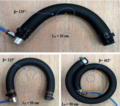
| L0 (cm) | Measured Bending Angle (Degree) | Calculated Bending Angle (Degree) | Measured Bending Torque (Nm) | Calculated Bending Torque (Nm) |
|---|---|---|---|---|
| 20 | 135 | 137.5 | 45.126 | 44.27 |
| 30 | 215 | 217.38 | 68.67 | 66.48 |
| 50 | 462 | 463.8 | 107.91 | 110.09 |
| Pressure (kPa) | Width (cm) | Height (cm) | Radius (cm) |
|---|---|---|---|
| 0 | 30.0 | 0.0 | - |
| 50 | 29.5 | 1.9 | 58.20 |
| 100 | 26.9 | 4.9 | 20.91 |
| 150 | 24.1 | 7.9 | 13.14 |
| 200 | 20.1 | 9.4 | 10.07 |
| 250 | 17.2 | 9.8 | 8.67 |
| 300 | 15.3 | 9.9 | 7.90 |
| 350 | 14.1 | 9.95 | 7.47 |
| 400 | 13.3 | 10.0 | 7.21 |
| 450 | 12.6 | 10.1 | 7.04 |
| 500 | 11.5 | 10.2 | 6.72 |
| L0 (cm) | b (cm) | n | Wr (cm) |
|---|---|---|---|
| 30 | 34.64 | 3.15 | 1.2 |
© 2020 by the authors. Licensee MDPI, Basel, Switzerland. This article is an open access article distributed under the terms and conditions of the Creative Commons Attribution (CC BY) license (http://creativecommons.org/licenses/by/4.0/).
Share and Cite
Al-Ibadi, A.; Nefti-Meziani, S.; Davis, S. The Design, Kinematics and Torque Analysis of the Self-Bending Soft Contraction Actuator. Actuators 2020, 9, 33. https://doi.org/10.3390/act9020033
Al-Ibadi A, Nefti-Meziani S, Davis S. The Design, Kinematics and Torque Analysis of the Self-Bending Soft Contraction Actuator. Actuators. 2020; 9(2):33. https://doi.org/10.3390/act9020033
Chicago/Turabian StyleAl-Ibadi, Alaa, Samia Nefti-Meziani, and Steve Davis. 2020. "The Design, Kinematics and Torque Analysis of the Self-Bending Soft Contraction Actuator" Actuators 9, no. 2: 33. https://doi.org/10.3390/act9020033
APA StyleAl-Ibadi, A., Nefti-Meziani, S., & Davis, S. (2020). The Design, Kinematics and Torque Analysis of the Self-Bending Soft Contraction Actuator. Actuators, 9(2), 33. https://doi.org/10.3390/act9020033