Article

Multi-Physical Design and Resonant Controller Based Trajectory Tracking of the Electromagnetically Driven Fast Tool Servo

1
School of Mechanical Engineering, Nanjing University of Science and Technology (NJUST), Nanjing 210094, China
2
College of Mechatronics and Control Engineering, Shenzhen University (SZU), Shenzhen 518060, China
*
Author to whom correspondence should be addressed.
Actuators 2020, 9(2), 28; https://doi.org/10.3390/act9020028
Submission received: 23 February 2020 / Revised: 3 April 2020 / Accepted: 10 April 2020 / Published: 12 April 2020

Abstract

:
In this paper, a voice coil motor (VCM) actuated fast tool servo (FTS) system is developed for diamond turning. To guide motions of the VCM actuator, a crossed double parallelogram flexure mechanism is selected featuring totally symmetric structure with high lateral stiffness. To facilitate the determination of the multi-physical parameters, analytical models of both electromagnetic and mechanical systems are developed. The designed FTS with balanced stroke and natural frequency is then verified through the finite element analysis. Finally, the prototype of the VCM actuated FTS is fabricated and experimentally demonstrated to achieve a stroke of ±59.02 μm and a first natural frequency of 253 Hz. By constructing a closed-loop control using proportional–integral–derivative (PID) controller with the internal-model based resonant controller, the error for tracking a harmonic trajectory with ±10 μm amplitude and 120 Hz frequency is obtained to be ±0.2 μm, demonstrating the capability of the FTS for high accuracy trajectory tracking.

1. Introduction

Fast tool servo (FTS) is a promoting servo axis that is widely engaged in combination with diamond turning that oscillates the diamond tool several times in each rotation of the workpiece clamped on the spindle to fabricate optical freeform surfaces, which have broadly received increasing demands in aerospace, defense, optical industries, and many more [1]. With the FTS system, it mainly consists of three subsystems, including the actuator to drive the cutting tool, the guiding mechanism to guide the motion of the actuator, and the feedback control system to guarantee the motion accuracy.
Within the last three decades, much effort has been devoted to improving the performance of the FTS system. In general, the actuator performs an important task with which the performance of FTS system is fundamentally determined. Nowadays, the piezoelectric actuators (PEA) [2,3] and the Lorentz electromagnetic force-based voice coil motor (VCM) [4,5] are the two most popular driving sources for the FTS. Zhu et al. [2] has design and proposed control methodology for a high-stiffness FTS system for freeform generation. In the design, the PEA actuation is guided by a flexure mechanism, and the tracking error found to be about 1% through adopting an adaptive terminal sliding mode controller. A piezoelectrically actuated 2-degree of freedom (2-DOF) FTS system was also reported in Ref. [3], and a novel Z-shaped flexure hinge was proposed to generate amplified motion along the z-axis. In performance testing, the stroke of about 27.03 micron and −8.379 to 7.544 micron is archived along z-axis and x-axis, respectively. The resonant frequency is about 200 Hz. Although the PEA has many unique advantages, it is strongly restricted by its small motion stroke, and accordingly, the deliberately designed flexure mechanisms are required to amplify the motions of the PEA for large stroke application. To satisfy the turning of freeform surfaces with large sagitta values, the VCM would be a better choice. For example, Liu, Q. et al. [4,5] has developed a long stroke FTS driven by a commercial VCM with a crossed leaf-type flexure hinge as guiding mechanism. The achieved stroke is about ±1 mm and first resonant frequency is 106.6 Hz following a percentage error about 0.2% for the stroke. With respect to the major of commercially available VCMs, the center part is fulfilled by soft magnetic material to construct the magnetic circuit [4,5]. Although it is convenient for the VCM design, but using VCM as actuating element in FTS there is a challenge for placing the sensors to capture the motion of the tool.
With the VCM actuated FTS, the air bearing and flexure mechanism are two basic guidance mechanisms to support and guide the motion of the tool. Usually, the air bearing can achieve quite long stroke motion without mechanical contact. However, the air-bearing cost is very high due to the tight manufacturing and assembly tolerance of its key components [6]. The flexure mechanism is promising to serve as the bearing for guiding motions in the micro-meter scale up to the millimeter scale because of its friction-free motion capability, increased precision reliability, and low cost [4,5]. Therefore, it is more efficient to work for the short and medium stroke FTS. Currently, the design of the flexure mechanism mainly focused on the stiffness along the desired motion direction, and the lateral stiffness was mainly ignored which is especially important for FTS turning considering the cutting force in the free space.
Another issue related to the VCM actuated FTS would be the tracking accuracy of the trajectory. Since force density of the VCM is essentially low, the VCM actuated FTS usually has very limited bandwidth which will normally lead to a poor trajectory tracking accuracy for high-frequency trajectory tracking. Considering the (quasi-)periodic nature of the trajectory for FTS diamond turning of freeform surfaces, the repetitive control (RC) was developed to ultra-finely track the components with specified frequencies [7]. However, with the RC, a low-pass filter is essentially required to stabilize the control system which will deteriorate the tracking accuracy, especially when the tracking frequency approaches the cut-off frequency of the filter. Furthermore, design of the RC corresponding to the trajectory with multiple harmonic components which do not share the same fundamental frequency would be more complicated. The resonant controller (or called the adaptive feedforward cancellation (AFC) [8,9]) using a set of parallel resonators to ultra-finely track the trajectory components with the resonant frequency is very promising for accurately track the (quasi-)periodic trajectory in a simple and effective way. It was demonstrated to be effective for FTS turning driven by the normal-stressed electromagnetic force [9].
With these aforementioned discussions on the three main aspects of the FTS, the multi-physical parameters of both the electromagnetic and mechanical part of a VCM actuated FTS is deliberately designed. The electromagnetic circuit is designed to leave a space for placing the capacitive sensor to sufficiently capture the unidirectional motion of the tool, and a crossed flexure mechanism using four sets of identical parallelogram mechanisms is designed to improve the lateral stiffness. Finally, the resonant controller is applied to achieve a high accuracy for high-frequency trajectory tracking.

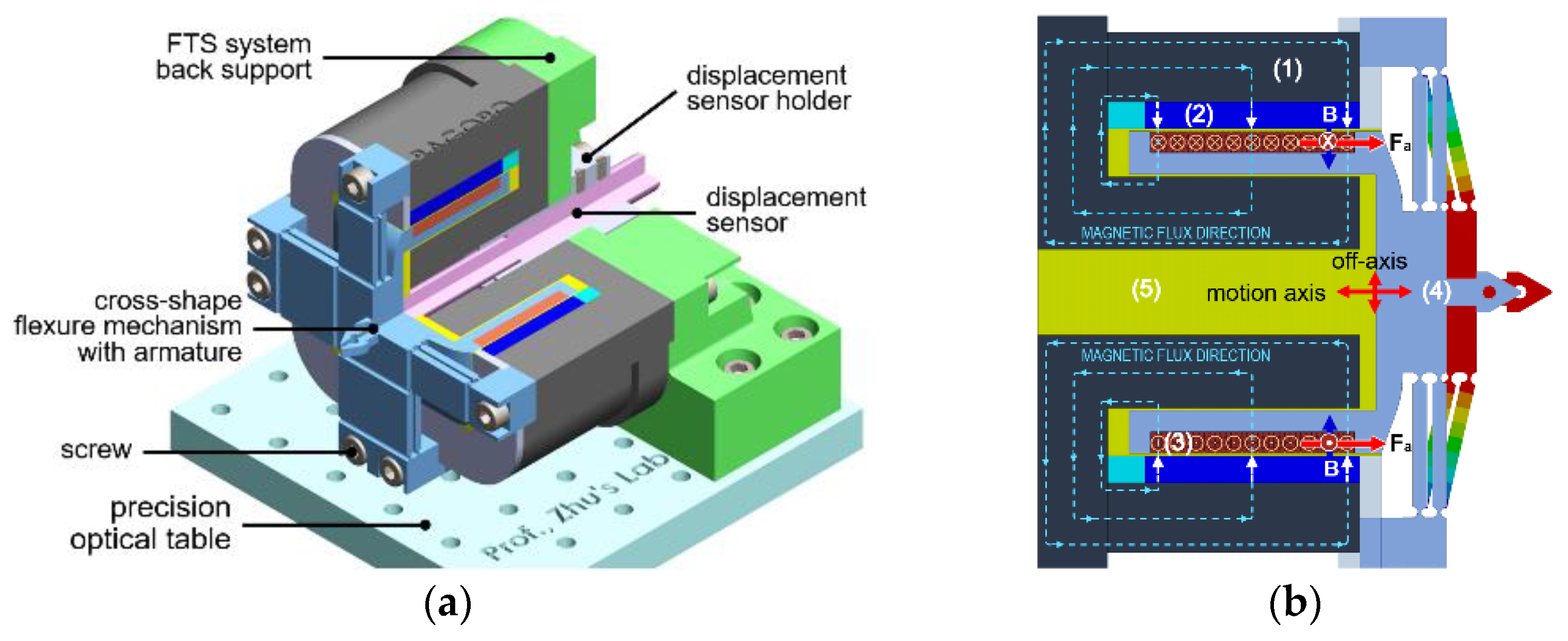
2. Architecture of the VCM Actuated FTS System

The three-dimensional design of the VCM actuated FTS system is illustrated in Figure 1. The armature of a cuboid-shaped VCM was designed to be fixed with the single-axis flexure mechanism. With the flexure mechanism illustrated in Figure 2, a crossed double parallelogram mechanism was designed to simultaneously improve the axial motion accuracy and the lateral stiffness to effectively bear the spatial cutting force. To guarantee a good capture of the tool motion, a capacitive displacement sensor is arranged through the center of the VCM to target at the center of the tool holder, which agrees with the center axis of the motion.
The working principle of the VCM actuated FTS is further shown in Figure 1b. A Lorentz-force generated by the interaction between the magnetic field and the current carrying coil. The force drives the armature which is fixed with the flexure mechanism. In principle, the generated force ( F a ) is proportional to the input current, flux density, and equivalent length of the coil inside the magnetic field, which is [10].
F a =   i d l × B a v i l B a v = B a v i ( N T l )
where i ,   l ,   a n d   B a v are the applied current, the length of coil within the magnetic field, and average magnetic flux density in the air gap. N T represents number of turns in case of multiple number of turns in the coil.

2.1. Design of the Voice Coil Motor

In the cuboid-shaped structure of VCM, the major parts consist of a stator (core and yoke), permanent magnet (PM), coil, and mover (joint design of armature of VCM and flexure hinge) as shown in Figure 1. The PM is a source to generate magnetic flux, these magnetic fluxes cross the small air-gap and enter into the coil and armature, and then connect with stator. Finally, a complete closed-loop path was developed for magnetic flux inside the VCM body as illustrated in Figure 1b.
Focusing the coil configuration, Assume l c = d i a × N t and h c = d i a × N l are the efficient length and height for multiple turns and layers in the coil, where d i a is the diameter of copper wire used in coil. The total number of turns ( N T ) in the coil can be expressed by N T = N t × N l . The total length for a single turn in coil is l = 4 w that is within the magnetic field where w is the width of PM. The total equivalent length of coil can be expressed as l T = l × N T . The parameters for the armature where the coil was made is given in Table 1.
In material selection, NdFeB (N52) was selected for the PM whose magnetic remanence is 1.47 T. Soft iron (AISI 1010) was chosen for the stator, whose relative permeability is nonlinear. Copper wire (AWG23) with a current rating three ampere is selected for the winding. Aluminum was selected for the mover. The PM holder was designed to support and hold PMs inside the yoke. High reluctant material was selected for PM holder so that it can stop the leakage flux from the sides of PM. A relatively large gap (vacuum) was kept at the back of armature in the moving axis to provide free reciprocating motion. The selected geometric parameters of VCM is given in Table 2.

2.2. Design of the Flexure Mechanism

As shown in Figure 1, a flexure mechanism using two crossed identical double parallelogram mechanisms was designed to connect with the armature. As illustrated in Figure 2, each parallelogram mechanism consists of two parallel linkages, and each linkage was serially connected by two right-circular flexure hinges (RCFH) and one rectangular leaf-spring flexure hinge (LSFH) with thickness b. The RCFH provided relative rotation between two adjutant rigid members through elastic bending. The crossed double parallelogram mechanisms will not only support the desired unidirectional motion, but also constrained the undesired parasitic motions with enhanced lateral stiffness.
In general, the structural dimensions, as marked in Figure 2, greatly influenced the working performance of the mechanism. Through manually tuning the parameters affiliated by the system models as established in Section 3, the selected parameters are summarized in the Table 3 to meet the desired motion stroke and natural frequency.

3. Modeling and Verification of the VCM Actuated FTS System

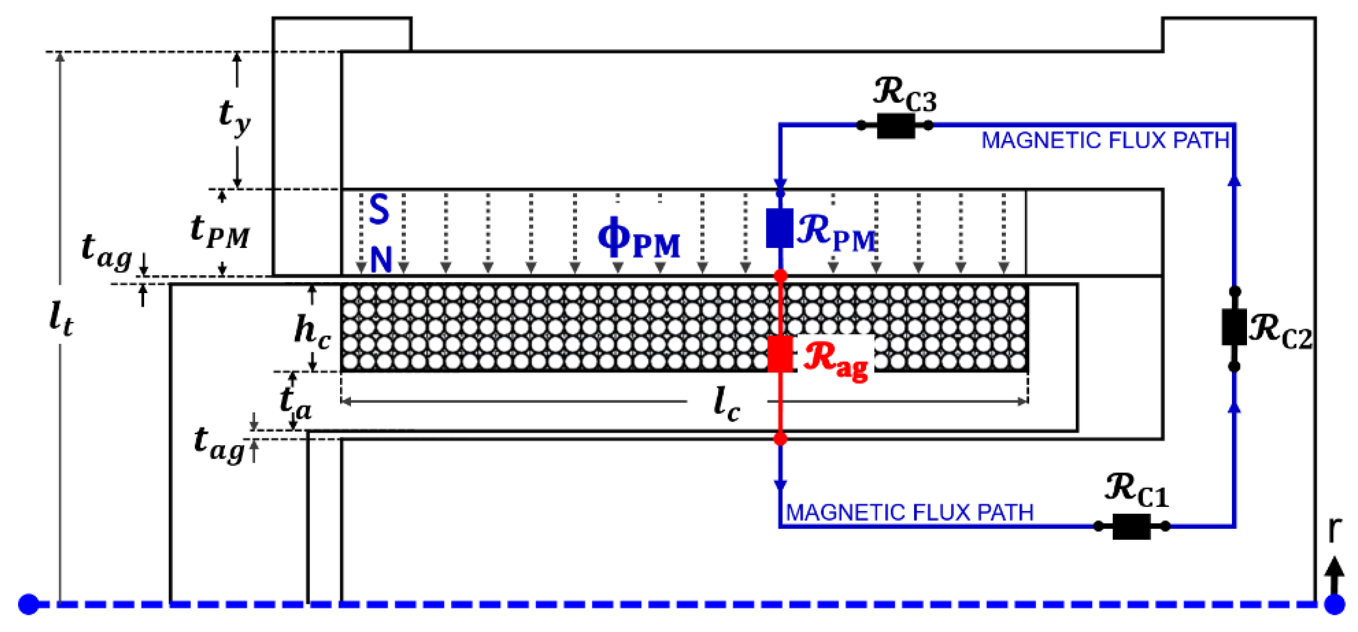
3.1. Magnetic Equivalent Circuit Modeling

The magnetic equivalent circuit (MEC) modeling can be used to find magnetic flux densities at any point in the magnetic circuit. The mathematical expressions for magnetic flux densities can be obtained by approximations with magnetic circuit elements [11,12]. An axis-symmetry cross-section view of the magnetic circuit of the designed VCM is illustrated in Figure 3, where all structural parameters are represented with lumped circuit elements.
With the equivalent circuit shown in Figure 3, the magneto-motive force ( F m ) generated from PM can be expressed by [11,12].
F m = B r t P M μ P M
where B r = 1.47   T is the remanence of the PM and μ P M is the relative permeability of the PM material. Ignoring the reluctance of the stator and the leakage flux, the reluctance of the PM and air-gap can be approximately expressed by [11,12]
P M = t P M μ P M A P M
a g = t a g μ a g A a g
where, A P M and A a g are the cross-section area of PM and air-gap, and the relative permeability inside the air-gap is μ a g .
The general magnetic flux expression can be expressed using Ohm’s law for the equivalent magnetic circuit, and the magnetic flux density ( B a g ) inside the air-gap can be obtained as
B a g = Φ a v A a g = F m A a g ( P M + a g ) = B r t P M μ P M A a g ( P M + a g )

3.2. Modeling of Flexure Mechanism

To obtain the stiffness of the developed flexure mechanism, the matrix-based compliance modeling (MCM) method in [3,13] is adopted. With the support of MCM in reference [3,13], the compliance C A 1 and C A 2 of the flexible linkages A 1 and A 2 in Figure 2 can be expressed in the global coordinate system as
C A 1 o = T O 1 C O 1 R ( T O 1 ) T + T O 2 C O 2 R ( T O 2 ) T + T 3 C O 3 L ( T O 3 ) T
C A 2 o = T O 4 C O 4 R ( T O 4 ) T + T O 5 C O 5 R ( T O 5 ) T + T O 6 C O 6 L ( T O 6 ) T
where C O i R and C O i L represent the basic compliance matrix of the RCFH [14] and LSFH [15] locally expressed in the system Oi, and T O i means the coordinate transfer matrix from system Oi to the global system [13].
Considering the parallel configuration of the two parallel linages ( A 1 and A 2 ), the total compliance of A 1 and A 2 at O x y can be expressed by
C L o = ( ( C A 1 o ) 1 + C A 2 o 1 ) 1
Similarly, the total compliance of the double parallelogram mechanism can be obtained as
C d p o = ( C L o 1 + ( T Y ( π )   C L o   ( T Y ( π ) ) T ) 1 ) 1
where T Y ( π ) is the transformation matrix around the y-axis with an angle of π . Taking advantage of symmetric structure of flexure hinge, the resultant stiffness of the flexure mechanism can be expressed by
K o = C d p o 1 + ( T Z (   π 2   )   C d p o   ( T Z (   π 2   ) ) T ) 1
where T Z ( π / 2 ) is the transformation matrix around the y-axis with an angle of π / 2 . Considering the symmetric feature of the mechanism, its input stiffness can be obtained as k i n = K o   ( 2 ,   2 ) . Considering the maximum current carried by the coil, the maximum stroke can be derived as
s = B a v I m a x ( N T l ) k i n
where I m a x is the maximum allowable current of the coil, which was selected as 1.6 A in this study.
The flexure mechanism regards as an equivalent damped mass-spring system from dynamic point of view [16]. The Lagrangian equation was used to derive the dynamic model [16]. Taking advantage of the symmetric structure of the flexure mechanism, the kinetic energy can be obtained as
T = I y 2 ( x ˙ l 1 ) 2 n l + m 1 2 x ˙ 2
where, x is the generalized coordinate, n l = 8 is the total number of linkages, I y is the moment of inertia of the flexure hinge, and m1 is the mass of the end-effector. Using the Lagrangian equation, the equivalent moving mass M can be expressed by [16]
M = T x ˙ = m 1 + m c + n l I y l 1 2
where, m c is the mass of the coil, which can be expressed comparing material density.
Therefore, the first natural frequency of the VCM actuated FTS system can be obtained by
f o = 1 2 π k i n M

3.3. Finite Element Analysis Validation

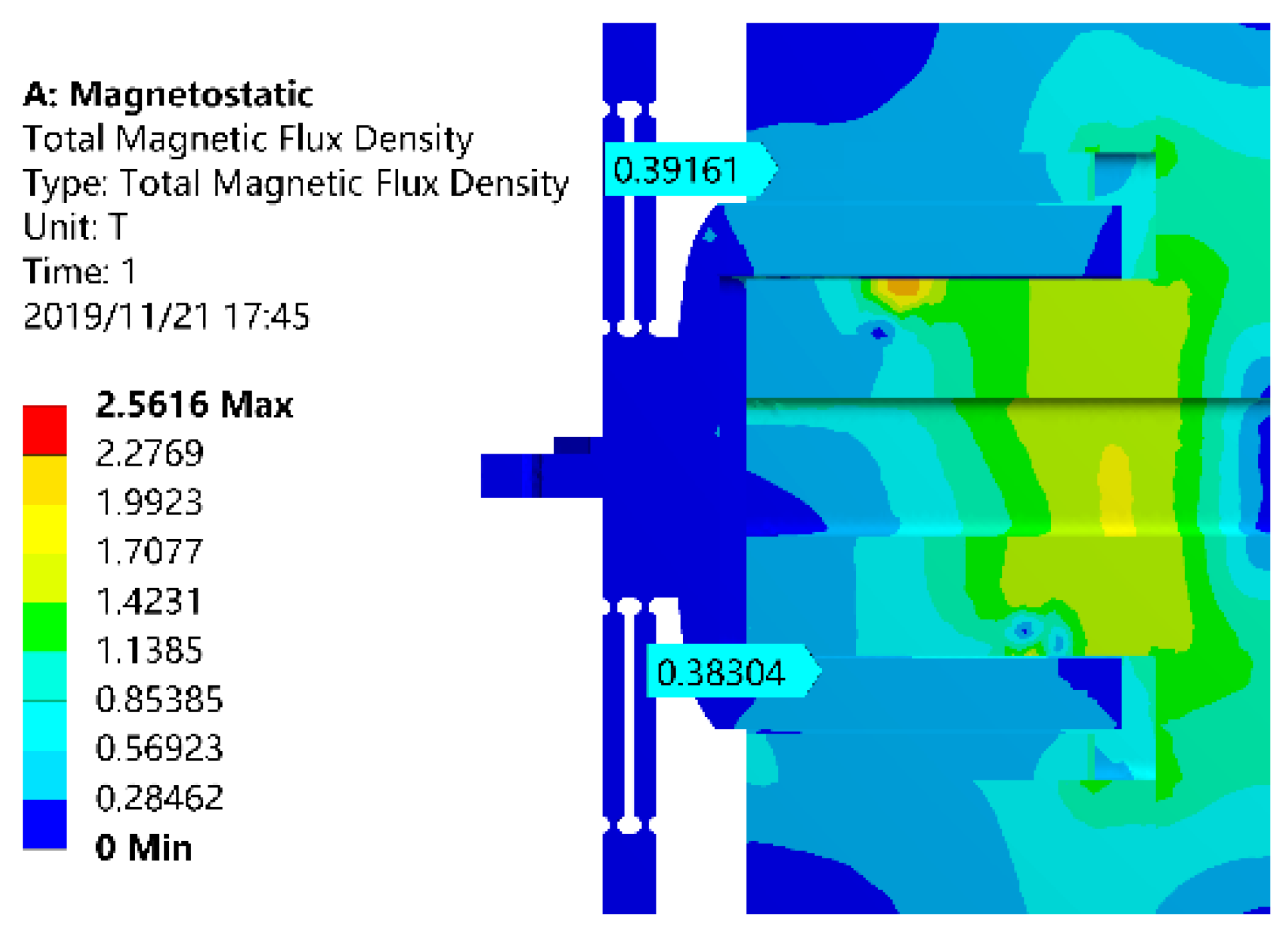
3.3.1. Electromagnetic Verification of the VCM

To validate the respective analytical models of the VCM actuated FTS system, finite element analysis (FEA) was carried out in ANSYS workbench. To validate the MEC modeling, a magnetostatic analysis was conducted. The total magnetic flux density distribution inside the magnetic circuit of VCM is shown in Figure 4. The average magnetic flux density inside the air-gap was observed to be about 0.383 T, and a relative modeling error of about 12.79% was obtained considering value of 0.432 T for the analytical result. The FEA and analytical results are comparatively summarized in Table 4.

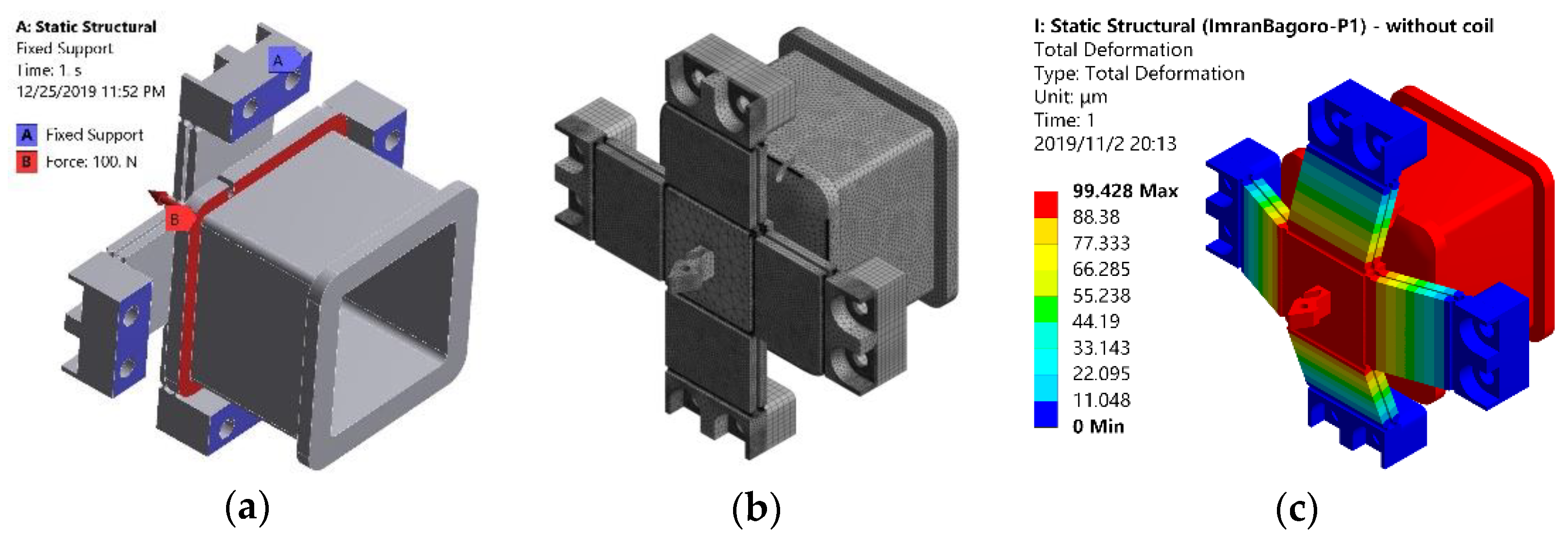
3.3.2. Mechanical Verification of Flexure Mechanism

To validate the stiffness model, a static structural analysis was conducted. The aluminum alloy was selected for the simulation which has a modulus of elasticity is 69 GPa, passion ratio of 0.33, and mass density of 2770 kgm-3. The constrain was applied as shown in Figure 5a, where plane A was fixed-end and plane B was free-end. To mesh the body, a proximity and curvature-based function was selected for the finest meshing, and the meshed body is shown in Figure 5b.
Through applying a force of F = 100 N on the free-end along the actuation direction, the total deformation of 99.428 μm was obtained as shown in Figure 5c which suggests a stiffness of 1.01 N/μm.
Moreover, to confirm the dynamic model, the modal analysis was conducted using the same constrains, mesh, and material. From the modes shown in Figure 6, the first natural mode agrees well with the desired motion, and the first natural frequency with and without considering the mass of coil were obtained to be 377.95 Hz and 229.91 Hz, respectively. From the comparative result summarized in Table 4, the maximum modeling error for both electromagnetic and mechanical part was less than 13%, suggesting that the developed model was reliable for the analysis and design of the VCM actuated FTS.

4. Controller Design for the Fast Tool Servo System

The control system adopts the PID controller as the control inner loop, and the outer loop adopts the adaptive feed-forward cancellation (AFC) controller to complete the tracking of the tool trajectory.

4.1. PID Controller

A typical PID controller was employed as the main controller for feedback control of the system, and the parameters are tuned through the loop-shaping method as reported in [17]. During the tuning, a desired open loop transfer function L d ( s ) was adopted which is expressed by L d ( s ) = ω c / s , where ω c is the design expected frequency.

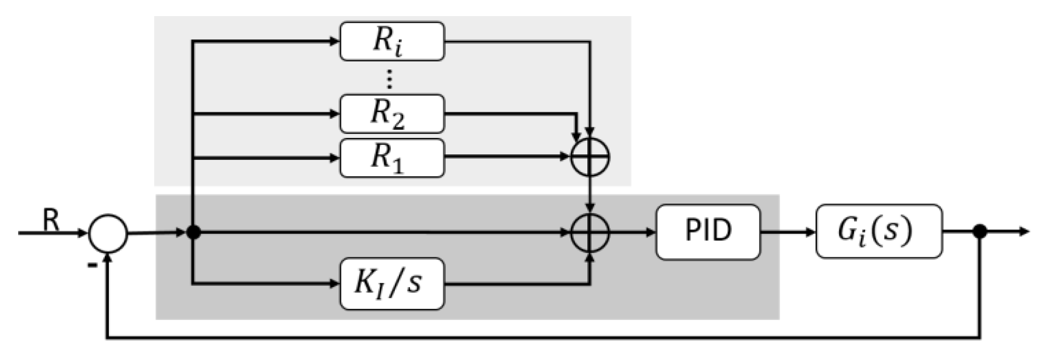
4.2. Resonant Controller

In the actual cutting process, the input signal and the external interference signal can be mainly decomposed into a series of harmonic signals [8]. Therefore, the resonant controller following the repetitive control principle was used to improve the tracking accuracy, and the main control loop was illustrated in Figure 7.
With respect to the resonant controller, the resonator can be expressed by [8]
R i ( s ) = g i s c o s Φ i + ω i s i n Φ i s 2 + ω i 2
where g i is a proportional gain for the i-th resonator. From Equation (15), the phase advance angle ( Φ i ) is used to adjust the zero position of the controller [8]. The Φ i obtained from the Bode diagram of the system after the introduction of PID control. With respect to the control process, the frequency ( ω i ) needs to be consistent with the desired frequency of the input signal.

5. Experimental Testing and Results

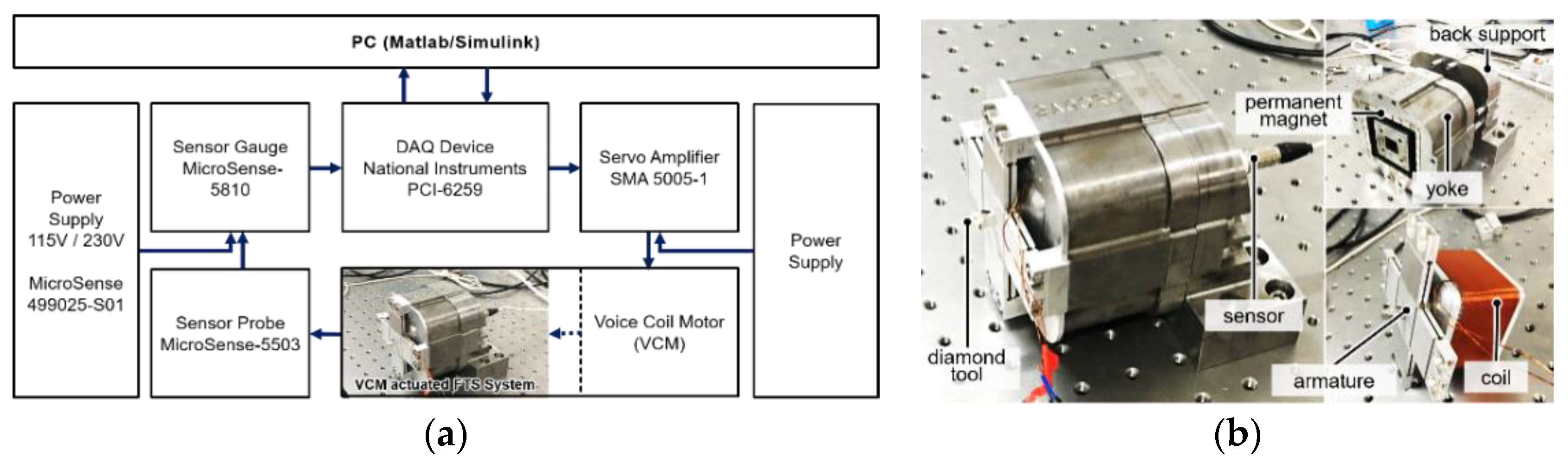
5.1. Experimental Setup

Scheme of the testing system is shown in Figure 8a, and a photography of the developed prototype is shown in Figure 8b. For the testing, a personal computer is used to generate a digital control signal via the data acquisition (DAQ) board through the Desktop Real-time modulus in Matlab/Simulink. The servo amplifier amplifies the voltage signal with a constant gain of 0.8 A/V for driving the mover of the FTS system. A capacitive sensor measures the motion and then delivers it to the DAQ board. Both open-loop and closed-loop testing were conducted through the Desktop Real-time modulus with a sampling frequency of 20 kHz.

5.2. Experimental Results

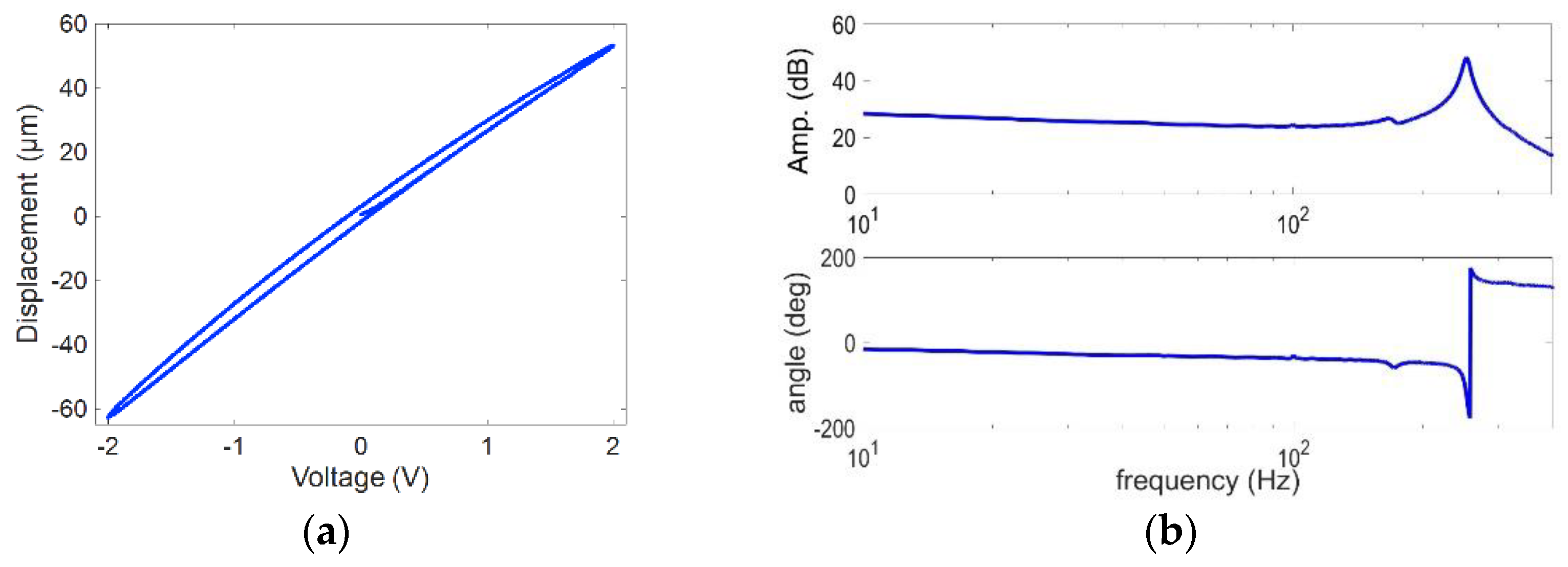
5.2.1. Static and Dynamic Performance Testing

To study the motion range, the experimental testing is carried out more than five times to ensure the performance results. The stroke of the FTS system subjecting to a sinusoidal command with an amplitude of 2 V was measured which led to a current of 1.6 A on the coil. The resulting stroke related to the sinusoidal command is shown in Figure 9a. The resulting stroke may range from −62.71 μm to 53.33 μm, showing a maximum stroke around ±59.02 μm. Moreover, a sweep excitation using a harmonic command with small amplitude and linearly varying frequency from 1 Hz to 1 kHz was conducted to get the frequency response feature. From the sharp peak of frequency response in Figure 9b, the first natural frequency was identified to be about 253 Hz.

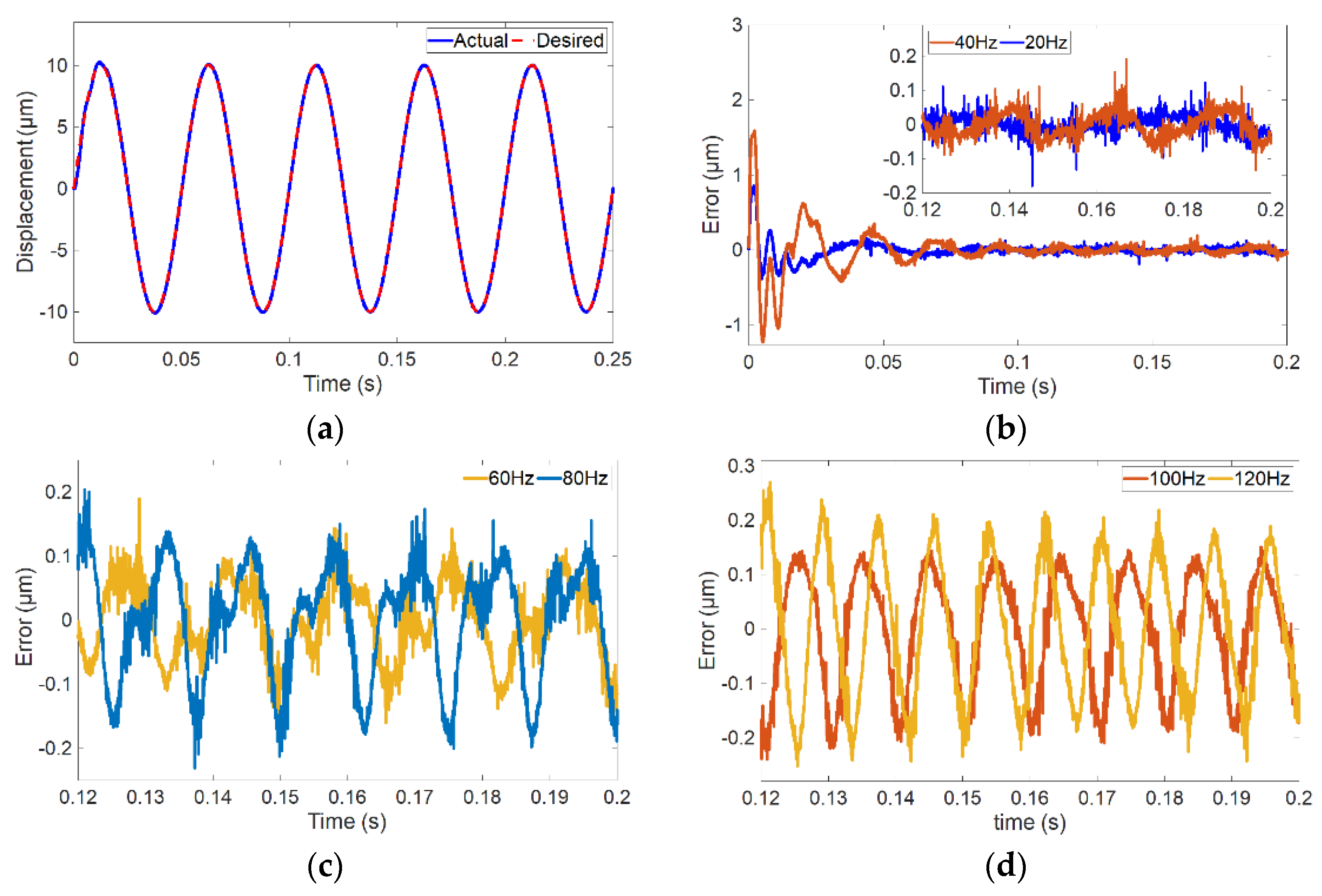
5.2.2. Control Performance Testing

The basic control performance test was conducted to track a harmonic signal with amplitude of 20 μm and frequency of 20 Hz, and the results are shown in Figure 10a. In this case, the designed controller can track the trajectory well, and the tracking error shown in Figure 10b suggests a relative error of about ±0.02%. Furthermore, a tracking of the harmonic signal with frequencies of 40 Hz, 60 Hz, 80 Hz, 100 Hz, and 120 Hz was performed. The tracking errors are illustrated in Figure 10b–d, and the tracking results are then summarized in Table 5 with the relative tracking errors.
From Figure 10b–d, the tracking error obviously increases with the increase of the desired frequencies. The position tracking error increased from 0.04 μm to 0.2 μm, and the relative position tracking error increased from ±0.2% to ±1%. When the frequency is higher than 120 Hz, the controller does not have a good tracking effect.

6. Conclusions

A voice coil motor actuated fast tool servo system was developed for diamond turning. The two essential components namely the actuator and flexure mechanism are deliberately designed to balance stroke and natural frequency. To facilitate the design of structural parameters of each component, the equivalent magnetic circuit model and matrix-based compliance model are established for the VCM and flexure mechanism, respectively. Finite element analysis on the magnetostatic, static structural, and model analysis is conducted to validate the designed system. The prototype of the VCM actuated FTS system is tested to have a stroke of ±59.02 μm and first natural frequency of 253 Hz. By constructing a closed-loop control using PID controller with the parallel resonant controllers, the error for tracking a set of harmonic commands with different frequencies is summarized. It suggests that although the tracking error increases with the increase of the tracking frequency, only ±1% maximum error is obtained when tracking a 120 Hz harmonic trajectory.

Author Contributions

Conceptualization, P.H. and Z.Z.; methodology, I.H. and W.X.; software, I.H. and D.Z.; formal analysis, I.H.; investigation, I.H. and W.X.; resources, Z.Z.; data curation, I.H., W.X., and D.Z.; writing—original draft preparation, I.H.; writing—review and editing, P.H. and Z.Z.; visualization, I.H.; supervision, Z.Z.; project administration, Z.Z.; funding acquisition, P.H. and Z.Z. All authors have read and agreed to the published version of the manuscript.

Funding

This research was funded by National Natural Science Foundation of China, grant number 51705254; Young Innovation Talents Program of Universities in Guangdong Province, grant number 2018KQNCX217.

Conflicts of Interest

The authors declare no conflict of interest. The funders had no role in the design of the study; in the collection, analyses, or interpretation of data; in the writing of the manuscript, or in the decision to publish the results.

References

  1. Rakuff, S.; Cuttino, J.F. Design and testing of a long-range, precision fast tool servo system for diamond turning. Precis. Eng. 2009, 33, 18–25. [Google Scholar] [CrossRef]
  2. Zhu, W.-L.; Yang, X.; Duan, F.; Zhu, Z.; Ju, B.-F. Design and adaptive terminal sliding mode control of a fast tool servo system for diamond machining of freeform surfaces. IEEE Trans. Ind. Electron. 2019, 66, 4912–4922. [Google Scholar] [CrossRef]
  3. Zhu, Z.; Zhou, X.; Liu, Z.; Wang, R.; Zhu, L. Development of a piezoelectrically actuated two-degree-of-freedom fast tool servo with decoupled motions for micro-/nanomachining. Precis. Eng. 2014, 38, 809–820. [Google Scholar] [CrossRef]
  4. Liu, Q.; Zhou, X.; Lin, J.; Xu, P.; Zhu, Z. A Quasiphysics Intelligent Model for a Long Range Fast Tool Servo. Sci. World J. 2013, 2013. [Google Scholar] [CrossRef] [PubMed] [Green Version]
  5. Liu, Q.; Zhou, X.; Liu, Z.; Lin, C.; Ma, L. Long-stroke fast tool servo and a tool setting method for freeform optics fabrication. Opt. Eng. 2014, 53, 092005. [Google Scholar] [CrossRef]
  6. Byl, M.F. Design and Control of a Long Stroke Fast Tool Servo. Ph.D. Thesis, Massachusetts Institute of Technology, Cambridge, MA, USA, 2005. [Google Scholar]
  7. Crudele, M.; Kurfess, T.R. Implementation of a fast tool servo with repetitive control for diamond turning. Mechatronics 2003, 13, 243–257. [Google Scholar] [CrossRef]
  8. Byl, M.F.; Ludwick, S.J.; Trumper, D.L. A loop shaping perspective for tuning controllers with adaptive feedforward cancellation. Precis. Eng. 2005, 29, 27–40. [Google Scholar] [CrossRef]
  9. Lu, X. Electromagnetically-Driven Ultra-Fast Tool Servos for Diamond Turning. Ph.D. Thesis, Massachusetts Institute of Technology, Cambridge, MA, USA, 2005. [Google Scholar]
  10. Brauer, J.R. Magnetic Actuators and Sensors; John Wiley & Sons: New York, NY, USA, 2006. [Google Scholar]
  11. Okyay, A.; Khamesee, M.B.; Erkorkmaz, K. Design and optimization of a voice coil actuator for precision motion applications. IEEE Trans. Magn. 2014, 51, 1–10. [Google Scholar] [CrossRef]
  12. Parmar, G.; Hiemstra, D.B.; Chen, Y.; Awtar, S. A moving magnet actuator for large range nanopositioning. In Proceedings of the ASME 2011 Dynamic Systems and Control Conference and Bath/ASME Symposium on Fluid Power and Motion Control, Arlington, VA, USA, 31 October–2 November 2011. [Google Scholar]
  13. Zhu, Z.; Zhou, X.; Wang, R.; Liu, Q. A simple compliance modeling method for flexure hinges. Sci. China Technol. Sci. 2015, 58, 56–63. [Google Scholar] [CrossRef]
  14. Wu, Y.; Zhou, Z. Design calculations for flexure hinges. Rev. Sci. Instrum. 2002, 73, 3101–3106. [Google Scholar] [CrossRef]
  15. Koseki, Y.; Tanikawa, T.; Koyachi, N.; Arai, T. Kinematic analysis of a translational 3-dof micro-parallel mechanism using the matrix method. Adv. Robot. 2002, 16, 251–264. [Google Scholar] [CrossRef]
  16. Zhu, Z.; Zhou, X.; Liu, Q.; Zhao, S. Multi-objective optimum design of fast tool servo based on improved differential evolution algorithm. J. Mech. Sci. Technol. 2011, 25, 3141–3149. [Google Scholar] [CrossRef]
  17. Sadeghpour, M.; De Oliveira, V.; Karimi, A. A toolbox for robust PID controller tuning using convex optimization. IFAC Proc. Vol. 2012, 45, 158–163. [Google Scholar] [CrossRef] [Green Version]
Figure 1. Mechanical structure of the voice coil motor (VCM) actuated fast tool servo (FTS) system, (a) the zonal-sectional view and (b) the cross-section view of the assembled structure, where (1) stator, (2) permanent magnet, (3) coil, (4) mover, and (5) air-part including air-gaps (yellow part).
Actuators 09 00028 g001
Figure 2. Cross-section view of the double parallelogram flexure mechanism, where R is radius of circular notch, t is thickness between two circular notches, a is the width and height of the linkage, and l 1 is the length of LSFH.
Actuators 09 00028 g002
Figure 3. Lumped-circuit element based magnetic circuit model of the VCM, where t P M , t a g , t a , and t y are the thickness of the permanent magnet (PM), air-gap, armature, and yoke, respectively. l t is the length from the outer face to the axis of the VCM. c 1 , c 2 , and c 3 are the equivalent reluctance of the stator material.
Actuators 09 00028 g003
Figure 4. Distribution of the magnetic flux density obtained by finite element analysis (FEA).
Actuators 09 00028 g004
Figure 5. Static structural analysis of the flexure mechanism, (a) the constraint, (b) the meshed model, and (c) the resultant deformation with F = 100 N.
Actuators 09 00028 g005
Figure 6. Modal analysis of the flexure mechanism, (a) the first mode without coil and (b) the first mode with coil.
Actuators 09 00028 g006
Figure 7. Control loop for the VCM actuated FTS system.
Actuators 09 00028 g007
Figure 8. Experimental setup, (a) schematic of the testing system and (b) the photography of the prototype.
Actuators 09 00028 g008
Figure 9. Response of experimental testing of the FTS system, (a) the output motion related to the applied voltage and (b) the frequency response function.
Actuators 09 00028 g009
Figure 10. The control performance, (a) tracking response for 20 Hz harmonic trajectory, (b) tracking error for 20 Hz and 40 Hz trajectory, (c) tracking error for 60 Hz and 80 Hz trajectory, and (d) tracking error for 100 Hz and 120 Hz trajectory.
Actuators 09 00028 g010
Table 1. Selected parameters for coil configuration, (copper wire (AWG23, 0.57mm diameter)).
SymbolDescriptionTurns/LayersValue
lcLength for multiple turns6437 mm
hcheight for multiple turns84.5 mm
NTTotal number of turns64 × 8512
Table 2. Selected geometric parameters of voice coil motor (unit: mm).
PartsGeometric ParametersSymbolsValue
Stator thickness (outer side of yoke)ty10
thickness (central iron core)tcr12
PMlengthlc + 340
thickness (magnetization direction)tPM5
widthw50
Armature thicknessta4.5
Air-gapthickness tag0.5
Table 3. Design parameters of flexure mechanism (unit: mm).
Rt l 1 ab
10.6282.630
Table 4. The analytical and FEA results of the FTS.
kin (N⁄μm)fo (Hz)B (T)Fa (N)s (μm)
Without CoilWith Coil
Ana.1.10395.51240.510.432132.7120.63
FEA1.01377.95229.910.383117.6116.49
Error8.91%4.65%4.61%12.79%12.78%3.55%
Table 5. Summarized tracking error in terms of different frequencies.
Freq. (Hz)20406080100120
Error (μm)±0.040±0.067±0.100±0.128±0.144±0.200
Percentage±0.02%±0.034%±0.05%±0.64%±0.72%±1.00%

