Abstract
This paper describes data-driven modelling methods and their use for the control of a novel set of series-elastic actuators (SEAs). A set of elastic actuators was developed in order to fulfill the end-user needs for tailored industrial collaborative robot manipulators of different morphologies and payloads. Three different types of elastic actuation were investigated, namely, disc springs, coil springs and torsion bars. The developed algorithms were validated both on single actuators and on a 6-DOF robotic arm composed of such actuators.
1. Motivation
Within the area of ‘Industrie 4.0’ [1], collaborative robots are a fundamental key technology that will likely immensely change future manufacturing. One of the key enabling technologies for collaborative robotics has been the different solutions (hardware and/or software) that provide inherent safety to those systems so that they can be used around humans with limited risk.
Though most industrial robots continue being held behind protection cages, a new generation of collaborative robots has appeared which share tasks until now only performed by humans (or which were partially automated), and in which human and robot share (at least temporarily) physical space, even having physical contact. Those collaborative robots are mainly used for performing repetitive tasks while the human can focus on tasks requiring higher cognitive abilities.
The list of collaborative robots has been increasing in the last years and continues to grow. We could however differentiate two categories of companies: Companies that have been created to exclusively commercialize a new type of collaborative robot and the ‘classical’ industrial robot companies which offer a new collaborative robot in their portfolios or have modified an existing design to make them suitable for collaborative tasks. This latter case would be of robots covered with shock-absorbing material as well as software solutions and new sensors that can detect collisions and safely stop the robot. From those, we could highlight the Fanuc CR-35iA [2], the Motoman HC10 [3], the COMAU AURA [4] or the pioneer KUKA lightweight robots [5]. From the first category, we could highlight the robot Sawyer developed by Rethink Robotics [6]. Rethink Robotics entered the market of collaborative robots in 2012 with the robot Baxter, a dual-arm robot, primarily for research and education. After the experience gained with Baxter, the company introduced the robot Sawyer, a robot manipulator for industrial use in collaborative tasks. The robots from Universal Robots [7] were the first robots developed with collaborative tasks in mind, the first ones being sold in 2009. In recent years, they have incorporated not only robots with different payloads (currently, 3, 5 and 10 kg), but also additional components such as cameras, grippers and software. The recent robot Franka [8] was presented in 2016 and first units were delivered in 2017. It is similar to the KUKA lightweight robots in the sense of using joint torque sensors to detect collisions.
While the first use of SEAs go back to 1995 [9], there has been a recent come back on the usage of series-elastic actuation, not only for the lower limbs of walking robots, but also, newly, on robot manipulators (such as the commercially available industrial robotic manipulator Sawyer [6], as previously mentioned) and even full humanoid robots. In the latter case, the most notable cases are the NASA robot Robonaut 2 [10] (in this case, elastic actuation is used in the arms), the THOR [11,12] and NASA-JSC Valkyrie [13] humanoid robots developed for the DARPA Robotics Challenge, or the humanoid COMAN [14]. Among the recent designs are also the quadruped robot ScarlETH based on high-compliant SEA legs [15], from which originates also the robot manipulator ANYpulator [16].
2. Related Work
As previously mentioned, a large number of SEA designs have already been developed over the last decades; they have been surveyed in [17,18,19] in great detail. Linear SEA is one of the classic designs and its elastic component is either composed by a single spring [9] or a set of springs connected in series [20]. The rotary series elastic actuators (RSEA) typically mount the springs around the shaft in a circle. For instance, Kong and Jeon proposed a compact RSEA design by using a coil spring and worm gears together, which is used for a knee joint assistance system [21]; in our previous work [22], the elastic element was a set of disc springs mounted at both sides of a lever. More recently, new elastic materials have also been investigated in the design of the SEAs: A magnetic nonlinear torsion spring is for instance integrated into a resonant parallel elastic actuator by Sudano et al. [23] for biorobotic applications; a torsionally-sheared rubber component is utilized by a team at the Carnegie Mellon University in their elastic actuator developed for a snake robot [24]. While many effects are reported in the studies of the new design, these elastic actuators still often suffer from poor linearity, which is derived from mechanical effects such as the properties of the rubber materials and different initial spring pre-compression.
Due to the inherent compliance from the elastic components, SEAs provide a “soft” contact force to the environment, which is a significant advantage compared to the rigid actuator. As a result, the torque control of SEAs has gained increasing interest in the past years, e.g., Wyeth [25] proposed a cascade control structure that controls the torque of the actuator by using an inner velocity loop. To control the interactive force between a parallel robot driven by three linear SEAs, Lee et al. [26], for instance, proposed a torque control approach that is composed of a joint level force control with disturbance observer and a higher level spatial force control to compensate the interactive force.
In this work, a set of actuators was developed which could be used to build industrial-class robot arms of different morphology and payload according to the end-user needs. In order to reach the goal of having industrial payloads similar to those currently available for collaborative robots (in the range of 3 kg to 14 kg), and in contrast to existing commercially available series-elastic actuators (such as ANYdrive from ANYbotics [27], with nominal torques up to 15 Nm, or the Hebi x-series actuators with torques up to 9 Nm [28]), a set of four actuators offering nominal torques up to 300 Nm was designed. The developed actuators make use of three different types of elastic elements (two already used in literature—disc and coil springs—and the use of a torsion bar with the novelty of passing through the hollow shaft of the rotary actuator to offer a compact size even for such high torques). As previously pointed out, the use of mechanical elasticity gives inherent mechanical compliance and contributes to the overall safety by absorbing possible unexpected collisions and, on the other hand, provides a torque estimation via the spring deflection measurement. In the case of industrial collaborative robots, it is a requirement for certification that a critical safety signal such as the torque measurement is redundantly measured from two different physical sources. For that reason, the developed motors used the torque estimation via spring deflection for the motor control, but the torque is estimated simultaneously via motor currents to double check that both torque estimations do not drift apart (in which case a safety stop would be triggered). Nonetheless, one the main focuses of this work is on developing a powerful and flexible data-based approach that models the elasticity of the actuator and that considers all possible non-linearities of the elastic couplings as an enabler for accurate torque control via spring deflection measurement. The data-based modeling approach is validated by using the newly designed rotary series elastic actuator.
The paper is organized as follows: Section 3 will briefly describe the mechanics and electronics of the elastic actuators, for a better understanding of the latter sections dealing with the modelling and control. Section 4 will describe the general actuator control structure, Section 5 will deal with the modelling and learning of the spring models, Section 6 will describe the experimental tests with single actuators and with a complete robotic arm composed of several of the actuators, and finally Section 7 will conclude the paper with a summary of results and the outlook.
3. Mechatronics
3.1. Mechanical Design
A set of actuators was developed which could be used to build modular industrial robot arms of different morphology, degrees of freedom, and payload according to the end-user needs. Moreover, the use of series-elastic actuation was selected in order to add a certain degree of passive mechanical compliance which could allow a higher degree of human–robot collaboration in industrial environments. The use of the spring element incorporates a safe manner (since it does not depend on sensors or software) to absorb unexpected shocks such as a collision with a human. Needlessly to say, that safety mechanism works to a certain extent depending on mass and speed of the moving robot but contributes to the overall inherent safety of the system and to additional safety measures. On the other side, since the deflection due to the spring is at the link side, a person trapped between the robot and a wall could likely free itself even when the system is stopped and joint brakes are switched on due to that small spring movement (approximately 5 degrees per joint). Additionally, this spring enables sensing the joint torques and thus, accurate torque control.
The elastic actuators consist of a brushless DC motor, a compact spring mechanism, Harmonic Drive gear, three high-precision position encoders (motor side, and both sides of the spring), mechanical brake as well embedded electronics including FPGA-based joint control and power electronics. The elastic actuators can be driven in torque, velocity or position control. The initial list of requirements was: Maximum continuous link-side torques from : 28 Nm, 50 Nm, 120 Nm and 300 Nm, a mechanical deflection ranging from at , the use of mechanical safety brakes and a compact and lightweight design. Four different actuator sizes were developed with torques 28 Nm, 50 Nm, 120 Nm and 300 Nm (at link side) (see Figure 1).
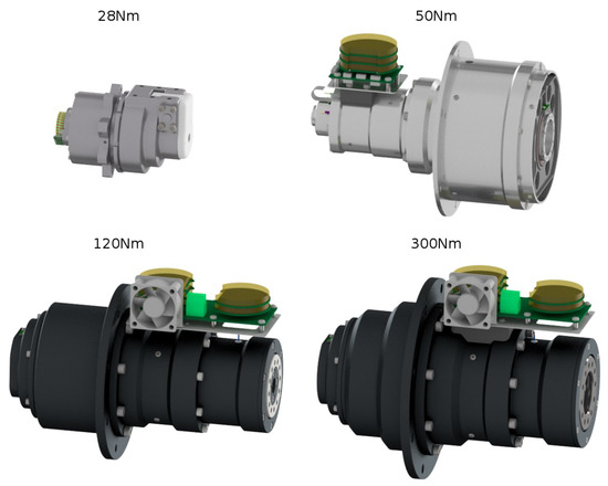
Figure 1.
The four complete serial-elastic actuators developed during the project (size in same scale).
According to the relative position of the spring within the actuator, the developed actuators are considered of FSEA (force-sensing series elastic actuator) type [18,29], since the spring is placed at the output of the gear (that is, between the load and the gear). In essence, the four actuator sizes are composed of the same components, which basically solely differ on the type of elastic element used (due to different size constraints). Figure 2 shows the relative position and type of the springs used for the different actuator types.
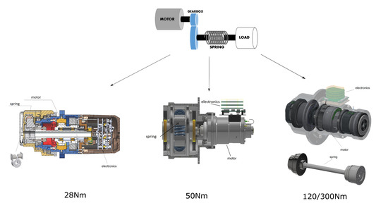
Figure 2.
Relative position and type of the spring for the developed force-sensing serial-elastic actuators (FSEA). Type of spring for each actuator; (left): Disc springs (28 Nm actuator), (middle): Coil springs (50 Nm actuator), (right): torsion bar (120 Nm and 300 Nm actuators).
All actuators come with pre-defined joint controllers running on the embedded electronics. The user can anytime externally access all the parameters of the joints (positions, velocities, torques, motor currents, controller gains, etc.) and, obviously, send new configuration parameters and reference signals. An overview of the main mechanical features of the four actuators is given in Table 1.

Table 1.
Main mechanical features of the designed actuators.
By using this variety of actuator sizes, the user can build custom robotic systems. For instance, six actuators of different sizes could be used to build an industrial-like manipulator. Similarly, several joints could be used to build the limbs of a legged robot. From the actuator point of view, the user can freely decide which and how many actuators of each size wants to use and connect them in any required mechanical configuration. The different actuator sizes together with the modular design allow creating custom robots, especially interesting for industrial-like applications in the area of collaborative robotics.
To develop the 28 Nm-actuator, the previous actuators designed within the project CAPIO [22]—which were already using an elastic element—were taken as starting point. The 28 Nm model of the family of compliant actuators is characterized by its very compact size and low weight, since usually these smaller joints will be used as wrist of a robotic manipulator or the last joints of a robotic leg. In order to keep the size under such compact size, a series of disc springs are used as elastic elements (see Figure 3(right)).

Figure 3.
(left): Assembled 28 Nm Actuator, (right): Detail of the elastic element (disc spring) and its placement within the actuator.
The 50 Nm model (Figure 4(left)) of the family of compliant actuators is characterized by using a series of coil springs (Figure 4(right)), which can be also exchanged to select the required stiffness for the application. This actuator has a hollow shaft, allowing easy cabling of the system to be built.

Figure 4.
(left): Assembled 50 Nm Actuator, (middle, right): Details of the elastic element (coil springs).
The 120 Nm andn 300 Nm models of the family of compliant actuators is characterized by a torsion bar going through the hollow shaft of the actuator. The torsion bar itself forms a hollow shaft which can be used for cabling going through the joint, additionally the use of the torsion bar as spring allows a highly-compact design. Figure 5 shows a detail of the new concept for the elastic element used in the 120 Nm and 300 Nm actuators.
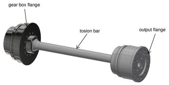
Figure 5.
Detail of the elastic element (torsion bar) of the 120 Nm and 300 Nm actuators.
3.2. Joint Electronics
The electronic of the SEA is developed based on our previous work [30]. The new design is composed of three PCBs which handle all the required sensors: The motor current sensors are integrated in the low phases of the three-phase H-bridges; two 19-bit absolute position encoders are placed at both sides of the gear, a third encoder is mounted after the spring element. An LVDS bus is used for communication to the high-level control with an in-house developed communication protocol (NDLCom [31]). To process this sensor information and control the SEA with the proposed control methods, a Spartan6 FPGA from Xilinx is used. The electronic specifications of the four SEAs are given and compared in Table 2.

Table 2.
Main electrical features of the designed actuators.
4. Joint Control
Deflection Controller
The FPGA-based robot joint controller is composed of two parts (Figure 6). The first part is a cascade of three PID controllers with feed-forward signals which control position, velocity, and motor current. The control mode is selected by configuration, for instance, so that the position controller is deactivated and velocity is controlled directly, or the position and velocity controller are deactivated and current is controlled directly. Nonetheless, if position or velocity limits are reached, the deactivated controllers will become active to keep the control variables within the limits.
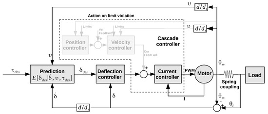
Figure 6.
Actuator controller structure, composed of a cascade of PI(D) controller and a model of the spring deflection.
The second part is a deflection controller. It controls the deflection of the spring element of the serial-elastic actuators by either acting on the velocity controller input or by directly acting on the motor current controller input. The deflection controller is also implemented according to a PID feed-back control law. The measured spring deflection is calculated by using two position sensors at both sides of the elastic element. The reference deflection on the other hand is estimated by using the dynamic Gaussian mixture model (DGMM) spring deflection model , with the first derivative of deflection , velocity v of the motor and desired torque . More details of the spring model is given in the following section.
In the experiments, the deflection controller acting on the velocity controller input was less responsive, more difficult to tune empirically, and this setup was tending to oscillations on the actuator output, most likely due to stiction effects. The deflection controller acting on the motor current controller was therefore chosen, as in this setup a responsive and stable closed-loop behavior could be easily achieved for an initial tuning.
The joint position and velocity controller are simultaneously working in the background. They are activated only in case a pre-defined limit of velocity or position is reached and then override the deflection controller. This allows a safe and convenient operation when performing experiments, because a complete stop of the system is avoided as far as the controllers can keep the system state within the limits. Currently, the computation and addition of feed-forward terms is not handled on this level, as the torque-deflection model described later on this paper captures the respective effects.
5. Spring Modeling
Traditionally, the spring elements of the SEAs are modelled with the Hooke’s law in a linearized form as presented for instance in [19]. The linear model fits the single spring system accurately, however, it cannot address the nonlinear effects that can be observed from more complex spring sets [22] or novel rubber elastic elements [24]. Therefore, a precise model of the elastic element is needed and has been in the last years investigated. For example, Ford et al. [32] developed an online calibration approach that can compensate for the spring nonlinearities and estimate the torque via spring deflection and motor current. Lu [33] proposed a neural-network based approach which successfully modelled the nonlinear effects of the spring and realized a stable velocity control. However, the online calibration approach depends on the accuracy of the current measurement and neural-networks are a black-boxes which lack of mathematical interpretability. For this reason, a dynamic Gaussian mixture model (DGMM)-based approach is here proposed, in which a DGMM model captures the nonlinear effects for the multi-spring elements while keeping its mathematical interpretability and provides the direct possibility of online learning and adaption.
5.1. Introduction to Dynamic Gaussian Mixture Model (DGMM)
A Gaussian mixture model (GMM) is a parametric probability model represented as a finite number of weighted Gaussian distributions, which is widely used for processing multivariate data due to its high-efficiency and flexibility. In this case, a dynamic Gaussian mixture model (DGMM) is used to represent the spring model (Equation (5)), which was firstly developed by [34] for modelling dynamic motion of a legged robots and then has been further developed to model the coil-spring system of an elastic actuator in our previous study [35]. Since the number of Gaussian components can vary to enable the model to optimally fit the system, the trained DGMM model is compact to be used in real-time control.
The DGMM represents a probability density function as a variable-sized set of “weighted Gaussian” pairs (Equation (1)).
where are the component Gaussian densities, m is the number of Gaussian components which is varying in training phase and each Gaussian function is represented as
with mean vector and covariance matrix . is the weight of each component Gaussian
The quantity x is the observation vector. In the spring model, the vector x is made up of variables , where is the output torque of the actuator, is the deflection, is the first derivative of the deflection and v is the velocity of the actuator. Therefore, the observation vector x is given by
Then, the DGMM-based spring model is represented by the joint probability density function:
5.2. Online Update Method
Since the elastic actuator is sampled at a high frequency (1 kHZ), in order to learn a compact model it is necessary to assess each new observation data before it is assimilated into the existing model. Therefore, an online update approach is used which is depicted in Algorithm 1.
| Algorithm 1: Spring Model Update. |
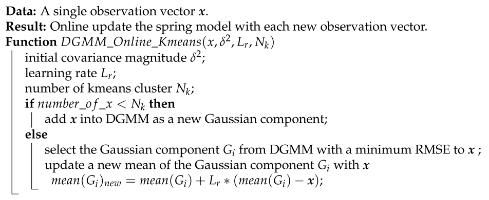 |
As can been seen from the algorithm, each new observed state of the system is evaluated with existing Gaussian components G. According to the predefined number of clusters , the new observed state will either be added as a new component or merged into existing component of the DGMM model in a learning rate defined by .
5.3. Gaussian Regression for Estimation
As illustrated in Figure 6, the desired deflection of the spring needs to be predicted with given reference torque by using the learned spring model Equation (5), from which the mean of a Gaussian component is given by:
and covariance by:
The conditional mean for Gaussian is a linear function given by
and the conditional variance is given by
Now the conditional mean of can be calculated by using
where
5.4. Model Transfer
Transfer learning is an approach to improve the efficiency of learning progress by transferring the knowledge from similar tasks that has already been learned. In order to allow and optimize a rapid progress in modelling of a new actuator, the knowledge (model) of a similar SEA can be used. In this section, we will discuss the possibility of model transferring from a learned spring model to new actuators.
Transferability
As it will be seen later, the different types of SEAs present common features such as a general linearity and hysteresis effects. Therefore in this task, a base model is firstly trained based on the dataset of one piece of SEA by using DGMM approach. Then the base model will be used to estimate the torque-deflection curves of the other SEAs. Since the dynamic effects of two pieces of SEAs are different, even if their mechanical structure are the same, a torque offset between estimated torque from base model and the measured torque of the new SEA is observed.
where are the measured deflection, first derivative of deflection, velocity and rotate position of the new actuator, respectively. represents the measured output torque and is the estimated torque. Since a large portion of the offset is a constant value , which can be easily calculated by using the samples measured from the new actuator at the beginning of the test, e.g., 100 samples from the first 0.97 s ( in Equation (13)). The performance of the transferred model can be improved significantly by compensating this constant offset especially for some new actuators with a very different nonlinear effects.
As a result the torque of the new actuator after the first i samples can be estimated by using
6. Experiments and Evaluation
6.1. Actuator
Torque Tracking Experiments
In order to validate the modelling approaches, a torque tracking experiment is conducted in a test setup as shown in Figure 7. A 120 Nm actuator is fixed on an adjustable base, so that the inclination of the actuator can be changed and the effects of gravity can be accounted for. A load (9 kg) is attached on a link lever with a distance of 80 cm to the output side of the actuator. An external force/torque sensor is mounted between the spring coupling and the link lever, which measures the output torque in a range of ±200 Nm with an accuracy class of 0.05%.
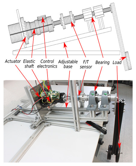
Figure 7.
Experimental setup used for spring modeling and validation of the torque control.
To evaluate the learned spring model using the DGMM approach and verify the proposed controller (Figure 6) in different torque ranges, a torque tracking experiment is conducted to control the output torque of the actuator to follow the chirp signals of different amplitudes. Figure 8 presents the results of tracking a reference output torque in the time domain, in which plot (a) illustrates the result of tracking a chirp signal with an amplitude of 70 Nm and plot (b) presents the result of tracking a chirp signal with an amplitude of 20 Nm. The black dash line represents the desired torque and red line shows the measured output torque controlled by using a DGMM-based controller. For the sake of comparison, a linear regression model based torque control is used and the tracking result is plotted in a blue line. As can be seen from plot (a) and (b), the SEA tracks the reference torque accurately when the reference signal is in a low frequency. The tracking errors of these two experiments are compared in plots (c) and (d). It can be observed that the torque control by using a DGMM model presents a much better result than by using a simple linear model in both two experiments: In the test of tracking the chirp signal with an amplitude of 70 Nm, the results of the DGMM based approach and linear regression approach reach a mean absolute deviation (MAD) and a standard deviation (STD) of 1.90 ± 2.42 Nm and 2.37 ± 1.94 Nm, respectively, (plot c); in the test of tracking the chirp signal with an amplitude of 20 Nm, it provides a result of 0.79 ± 0.62 Nm and 1.36 ± 1.18 Nm individually (plot d).
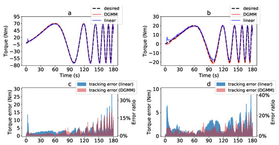
Figure 8.
(a) Torque tracking of a chirp reference signal with an amplitude of 70 Nm, (b) Torque tracking of a chirp reference signal with an amplitude of 20 Nm, (c) Tracking error of a chirp reference with an amplitude of 70 Nm. The mean absolute deviation and a standard deviation of the dynamic Gaussian mixture model (DGMM) and linear model based control reach 1.90 ± 2.42 Nm and 2.37 ± 1.94 Nm, respectively. (d) Tracking error of a chirp reference with an amplitude of 20 Nm. The mean absolute deviation and a standard deviation of the DGMM model and linear model based control reach 0.79 ± 0.62 Nm and 1.36 ± 1.18 Nm, respectively.
The advantages of the DGMM based approach with respect to the linear model based approach can also be evaluated by a ratio of their mean absolute deviations : The lower the ratio is, the larger the advantage the DGMM based approach provides. The ratios of the torque tracking experiments with a high torque reference (Amplitude = 70 Nm) and a low torque reference (Amplitude = 20 Nm) are 0.802 and 0.581, respectively. It can be observed that the DGMM based approach provides a more significant improvement in the low torque range, in which the nonlinear effects are more visible and difficult to be modelled by using a simple linear regression.
Moreover, taking the torque range into the consideration, an error ratio defined as the absolute error divided by the amplitude is calculated (right axis of plot (c) and (d)). The mean error ratio of the torque control is 2.71% and 3.39% by using a DGMM model and a linear model, respectively, in a high torque range (Amplitude = 70 Nm), and reaches 3.95% and 6.8% in a low torque range (Amplitude = 20 Nm). It can be noticed that since nonlinear effects of the SEA include a constant part (backlash and Coulomb friction), which in turn induce less disturbance for a high torque control, both controllers perform better in high torque range.
6.2. Spring Coupling Analysis
As shown in Figure 3, Figure 4 and Figure 5, a set of disc springs, coil springs and torsion-bars are used as the elastic elements of the four type SEAs, respectively. Theoretically, these springs should present a perfect linearity with the stiffness shown in Table 1. However, due to the internal friction in the spring component, different pre-compression during assembly and other manufacturing side-effects, the torque-deflection curves of the overall spring modules are non-linear. Figure 9 shows the results of the experiments and the non-linearity of the spring couplings. In these experiments, the elastic actuators are operated in position control to swing up to the fixed rotation angles. The motors are mounted on a test bed with a load on a link lever attached to the output side, which provide the external torque to motor through the spring element (see Figure 7). The torque ground truth can be provided by using an external force/torque sensor (Lorenz-DF30) in a range of ±50 Nm with an accuracy class of 0.05%. As can be seen from the result, the hysteresis characteristics are observed in all of the four spring elements, which is a result of the backlash and friction of the actuator. Since the link lever is controlled to swing more than 90 degree during the experiments for the 50 Nm, 120 Nm and 300 Nm actuators, two more hysteresis curves can be observed on both sides of the torque curve at plot b,c,d. Comparing the four torque curves, the 28 Nm and 50 Nm actuators present more obvious hysteresis characteristics and the torsion bar shows a better linearity.
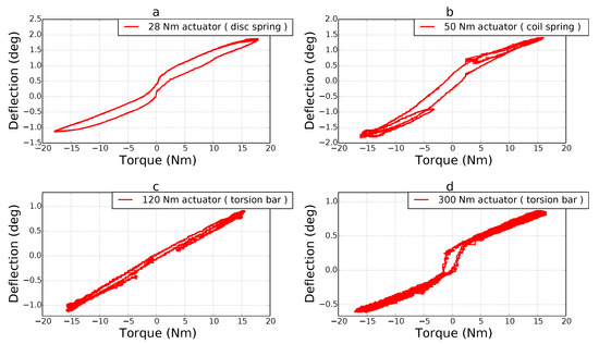
Figure 9.
Torque-deflection curves of the four actuators. The torques are measured by using an external force/torque sensor and the deflections are calculated as the difference of two absolute encoders at both sides of the spring.
6.3. Initial Results of Model Transfer
In order to validate the model transferring approach, two pieces of actuator (a 300 Nm actuator and a 50 Nm actuator) are used, from which the model of the 300 Nm actuator will be trained as the base model and the 50 Nm actuator is considered as a new actuator for testing. To capture the data of these two actuators, a position control experiment is conducted, which is the same as the experiment presented in Section 6.2. The left subplot of Figure 10 shows the measured torque-deflection curves of the two actuators in a three-dimension space (deflection, torque and rotate position), in which the blue, green, red and cyan curves represent the measured torque with respect to spring deflection and motor rotation position from four experiments with different loads on the 300 Nm actuator. The purple curve is the measured torque deflection curve from the 50 Nm actuator, which is a ground truth for validation.

Figure 10.
Initial result of model transferring from a 300 Nm actuator to a 50 Nm actuator. (a) measured torque-deflection curves of the two actuators in a three-dimension space (deflection, torque and rotate position), (b) estimated torque of a 50 Nm actuator using a 300 Nm actuator model.
In the training phase, the measured dataset of the 300 Nm actuator from the four tests (with different maximum torques) are used as the training data. According to the GMM based modelling method and the online updating approach, a based model with 5000 Gaussian components is trained from the measured dataset (approximately 216,000 samples). After training, the torque curve of the 50 Nm actuator is estimated by using Equation (14), results which are shown in the right subplot of Figure 10. As it can be seen, the red crosses are the measured torque as the ground truth for validation and the blue pluses are the estimated torque by using the transferred base model with given measured inputs from the 50 Nm actuator. Due to the differences between these two types of SEAs, the model of the 300 Nm could not estimate the torque of the 50 Nm actuator very precisely, even if the constant offset has been compensated. However, the general hysteresis effects and the linearity of the new actuator has been estimated by using the base model.
The transferability of the base model has also been validation on the other types of SEAs presented in this paper. Figure 11 shows the results of the torque estimation on four different types of SEAs by using the same base model (300 Nm actuator No. 03). The red dots lines represent the measured torques of each new actuator and the blue crosses lines are the estimated torques by using Equation (14) with the base model. From the results of the subplots, the hysteresis features of all the four actuators can be estimated by using the model learned from an extra actuator.
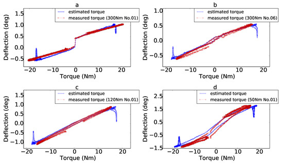
Figure 11.
(a) Results of the torque estimation on 300 Nm actuator No. 01. (b) Results of the torque estimation on 300 Nm actuator No. 06. (c) Results of the torque estimation on 120 Nm actuator No. 01. (d) Results of the torque estimation on 50 Nm actuator No. 01.
To evaluate the performance of the model transfer on each new actuator, root mean square errors (RMSEs) are calculated which are shown in Figure 12. The first bar (300 Nm No. 03) represents the estimation result by using the model learned from the actuator 300 Nm No. 03 with itself, but applied on an experiment with new load. The second bar (300 Nm No. 06) represents the estimation result by using the model learned from the actuator 300 Nm No. 03 applied on actuator 300 Nm No. 06. The third bar represents the estimation result by using the model learned from the actuator 300 Nm No. 03 applied on actuator 120 Nm No. 01, and the the fourth bar represents the estimation result by using the model learned from the actuator 300 Nm No. 03 applied on actuator 50 Nm No. 01. As the four bar results show, the torque estimation by using the model learned from another actuator is, as expected, not as good as the estimation by using the model learned from itself. Furthermore, the results of the 300 Nm No. 06 and 120 Nm No. 01 are, as expected, better than the 50 Nm No. 01 since these two actuators use the same type of spring as the one with which the model was learned from. Nonetheless, the method provides initial insights on the transferability, especially between actuators of the same type.
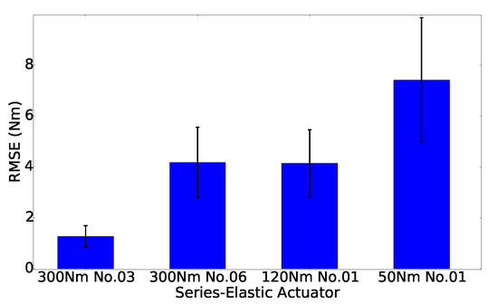
Figure 12.
Root mean square error (RMSE) and standard deviation of the transfer from model 300 Nm No. 03 to three other actuator types.
6.4. Arm
Once the single actuators were validated, a first prototype arm was built composed of the following actuators (from base to wrist): two 300 Nm actuators, one 120 Nm actuator, and three 28 Nm actuators. For the initial tests, a joint space trajectory was used with the joint configurations as shown in Figure 13. Later on, new versions of this prototype arm were used in several end-user applications (see Figure 14).
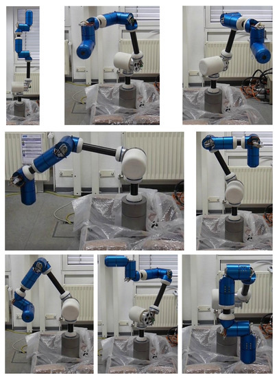
Figure 13.
Joint configurations of a joint space trajectory used as a first test of the assembled prototype arms.

Figure 14.
Two of the final prototypes at the end-user facilities; (left): Arm at the company STODT (The Netherlands) supporting a person during the loading and unloading of a machine; (right): Arm at the application scenario of the company WOLL (Germany) supporting a person during a welding task by holding and positioning of the workpiece (©FourByThree; permission granted).
As pointed out in the introduction, in order to get through a certification of the industrial arms, it is required to provide redundancy on the safety critical signals such as the torque. For this reason, we compare here motor-current based torque estimation with torque estimation based on spring deflection and gear deflection. The idea is to verify the similarity not only for a single standalone actuator, but using an assembled robotic arm, and therefore to validate the methodology, considering as well loads such as the links and the other joints. Contrary to the previous sections where different estimation methods have been compared for the spring elements, the focus of this paragraph is on the validation of the adequacy of the mechanical and redundant sensory arrangement. For this purpose, a coarse comparison of the measurements useful to detect failures of one of the measurement sources is carried out based on the obtained experimental data. For the comparison, the torque estimations in this experiment use linear models with additional terms to account for viscous and Coulomb friction.
In particular, the experimental data has been generated by moving one of the final prototype arms along a joint space trajectory similarly as shown in Figure 13. For three of the six joints of this prototype arm, Figure 15 shows the joint positions, velocities and estimated torques for one of each size of actuator. The torques are estimated from three different sources, namely the torque estimated from the motor current , the torque estimated from the difference in position from motor across the gear transmission, and the torque estimated from the difference in position across the elastic element. These torque estimates were obtained as follows.
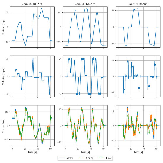
Figure 15.
Comparison of the different sources of estimated torque (bottom row) for a joint space trajectory (upper two rows); one type of actuator per column.
Firstly, for the further comparison, we estimate the motor torque using the torque constant and the gear transmission ratio :
Secondly, using as reference, the torques based on the spring and gear deflection measurement are estimated using a model which is linear wrt. four coefficients. These are, namely, for a measurement offset, for a linear scaling of the measurement, as viscous friction coefficient, and as Coulomb friction coefficient, each one for spring and gear deflection , respectively. Instead of a signum function for the Coulomb friction term, an function has been chosen as smooth approximation. Thus, for samples of measurement with sampling time T, we obtain the following equation for the torque estimated from the spring deflection:
Thirdly, Equation (16) is solved for the four coefficients numerically using a least squares estimator. The second and third step is carried out, respectively, for the gear deflection. To summarize, the different torque estimates are determined by
using the numerical values listed in Table 3. The resulting torques are shown in Figure 15. As it can be seen, there is mostly a good agreement in the shape of the torque measurements using these simplistic models with the estimated parameters. An exception is the gear deflection measurement of the 28 Nm actuator, where there is only a low load torque and other effects not captured by this model such as hysteresis effects may have a larger influence for this type of mechanical transmission. Nevertheless, the estimated motor torque and spring torque are in good agreement even for these low torques.

Table 3.
Coefficients used to compute the torque estimates depicted in Figure 15 according to Equations (17)–(19)
To summarize, the sensory arrangement provides multiple independent measurements which allow to redundantly estimate the load torque. Thus, we can validate the approach and support that we can contribute to the safety of such robotic systems from the mechanical side, due to the inherent compliance, and from the control perspective, via a redundant measurement of the actuator torque using distinct principles.
7. Conclusions and Outlook
A set of elastic actuators was developed in order to fulfill the end-user needs for tailored industrial collaborative robot manipulators of different morphology and payload. Three different types of elastic actuation were investigated, namely, disc springs, coil springs and torsion bars, the last being the most promising in terms of robustness, low wear, compact size and better dynamic characteristics. The focus of this work was to present data-driven methods for modelling and identification of such non-linear elastic elements for actuator control purposes as well as the possibilities to transfer learned models from one actuator to similar ones.
The future plans include new iterations of the 120 Nm and 300 Nm actuators to remove some manufacturing inaccuracies and the redesign of the 28 Nm and 50 Nm actuators with a more compact size with the use of the torsion bar concept. Moreover, the next step will include the safety certification of the actuators’ control electronics.
Author Contributions
Conceptualization, J.d.G.F. and V.B.; methodology, J.d.G.F.; control software, V.B.; modelling, B.Y.; mechanics, H.S.; electronics, M.Z.; writing—original draft preparation, J.d.G.F., B.Y., V.B.; writing—review and editing, J.d.G.F. All authors have read and agreed to the published version of the manuscript.
Funding
The FourByThree project received funding from the European Union’s Horizon 2020 research and innovation programme, under Grant Agreement No. 637095.
Conflicts of Interest
The authors declare no conflict of interest.
References
- Kagermann, H.; Lukas, W.D.; Wahlster, W. Industrie 4.0: Mit dem Internet der Dinge auf dem Weg zur 4. Industriellen Revolution. Available online: http://www.vdi-nachrichten.com/Technik-Gesellschaft/Industrie-40-Mit-Internet-Dinge-Weg-4-industriellen-Revolution (accessed on 23 March 2019).
- CR-35iA Collaborative Robot from Fanuc. Available online: http://www.fanuc.eu/pt/en/robots/robot-filter-page/collaborative-cr35ia (accessed on 23 March 2019).
- Motoman HC10 Collaborative Robot from Yaskawa. Available online: https://www.yaskawa.eu.com/en/news-events/news/article/news/motoman-hc10-collaborative-robot-safe-and-flexible-interaction/ (accessed on 23 March 2019).
- AURA Collaborative Robot from COMAU. Available online: http://www.comau.com/EN/media/news/2016/06/comau-at-automatica-2016 (accessed on 23 March 2019).
- KUKA LBR iiwa. Available online: www.kuka-lbr-iiwa.com (accessed on 23 March 2019).
- Rethink Robotics. Available online: www.rethinkrobotics.com (accessed on 23 March 2019).
- Universal Robots. Available online: www.universal-robots.com (accessed on 23 March 2019).
- Franka Robot from KBee AG. Available online: https://www.franka.de/ (accessed on 23 March 2019).
- Pratt, G.; Williamson, M. Series Elastic Actuators. In Proceedings of the IEEE International Conference on Intelligent Robots and Systems, Pittsburgh, PA, USA, 5–9 August 1995; pp. 399–406. [Google Scholar]
- Diftler, M.A.; Mehling, J.S.; Abdallah, M.E.; Radford, N.A.; Bridgwater, L.B.; Sanders, A.M.; Askew, R.S.; Linn, D.M.; Yamokoski, J.D.; Permenter, F.A.; et al. Robonaut 2—The first humanoid robot in space. In Proceedings of the 2011 IEEE International Conference on Robotics and Automation, Shanghai, China, 9–13 May 2011; pp. 2178–2183. [Google Scholar]
- Knabe, C.; Seminatore, J.; Webb, J.; Hopkins, M.; Furukawa, T.; Leonessa, A.; Lattimer, B. Design of a series elastic humanoid for the DARPA Robotics Challenge. In Proceedings of the 2015 IEEE-RAS 15th International Conference on Humanoid Robots (Humanoids), Seoul, Korea, 3–5 November 2015; pp. 738–743. [Google Scholar]
- Hopkins, M.A.; Ressler, S.A.; Lahr, D.F.; Leonessa, A.; Hong, D.W. Embedded joint-space control of a series elastic humanoid. In Proceedings of the 2015 IEEE/RSJ International Conference on Intelligent Robots and Systems (IROS), Hamburg, Germany, 28 September–3 October 2015; pp. 3358–3365. [Google Scholar]
- Paine, N.; Mehling, J.S.; Holley, J.; Radford, N.A.; Johnson, G.; Fok, C.L.; Sentis, L. Actuator Control for the NASA-JSC Valkyrie Humanoid Robot: A Decoupled Dynamics Approach for Torque Control of Series Elastic Robots. J. Field Robot. 2015, 32, 378–396. [Google Scholar] [CrossRef]
- Tsagarakis, N.G.; Morfey, S.; Cerda, G.M.; Zhibin, L.; Caldwell, D.G. COMpliant huMANoid COMAN: Optimal joint stiffness tuning for modal frequency control. In Proceedings of the 2013 IEEE International Conference on Robotics and Automation, Karlsruhe, Germany, 6–10 May 2013; pp. 673–678. [Google Scholar]
- Hutter, M.; Remy, C.D.; Hoepflinger, M.A.; Siegwart, R. High Compliant Series Elastic Actuation for the Robotic Leg ScarlETH. In Proceedings of the International Conference on Climbing and Walking Robots (CLAWAR), Paris, France, 6–8 September 2011. [Google Scholar]
- Bodie, K.; Bellicoso, C.D.; Hutter, M. ANYpulator: Design and control of a safe robotic arm. In Proceedings of the 2016 IEEE/RSJ International Conference on Intelligent Robots and Systems (IROS), Daejeon, Korea, 9–14 October 2016; pp. 1119–1125. [Google Scholar]
- Yu, H.; Huang, S.; Thakor, N.; Chen, G.; Toh, S. A novel compact compliant actuator design for rehabilitation robots. In Proceedings of the IEEE International Conference on Rehabilitation Robotics, Seattle, WA, USA, 24–26 June 2013. [Google Scholar]
- Paine, N.; Oh, S.; Sentis, L. Design and Control Considerations for High-Performance Series Elastic Actuators. IEEE/ASME Trans. Mechatron. 2013, 19, 1080–1091. [Google Scholar] [CrossRef]
- Junior, A.G.L.; Andrade, R.M.d.; Filho, A.B. Series Elastic Actuator: Design, Analysis and Comparison. In Recent Advances in Robotic Systems; Wang, G., Ed.; InTech: Rijeka, Croatia, 2016; Chapter 10. [Google Scholar]
- Arumugom, S.; Muthuraman, S.; Ponselvan, V. Modeling and application of series elastic actuators for force control multi legged robots. J. Comput. 2009, 1, 26–33. [Google Scholar]
- Kong, K.; Bae, J.; Tomizuka, M. A Compact Rotary Series Elastic Actuator for Human Assistive Systems. Trans. Mechatron. 2011, 17, 288–297. [Google Scholar] [CrossRef]
- Mallwitz, M.; Will, N.; Teiwes, J.; Kirchner, E.A. The CAPIO Active Upper Body Exoskeleton and its Application for Teleoperation. In Proceedings of the 13th Symposium on Advanced Space Technologies in Robotics and Automation, Noordwijk, The Netherlands, 11–13 May 2015. [Google Scholar]
- Sudano, A.; Tagliamonte, N.; Accoto, D.; Guglielmelli, E. A Resonant Parallel Elastic Actuator for Biorobotic Applications. In Proceedings of the IEEE/RSJ International Conference on Intelligent Robots and Systems (IROS), Chicago, IL, USA, 14–18 September 2014. [Google Scholar]
- Rollinson, D.; Ford, S.; Brown, B.; Choset, H. Design and modeling of a series elastic element for snake robots. In Proceedings of the ASME 2013 Dynamic Systems and Control Conference, Palo Alto, CA, USA, 21–23 October 2013. [Google Scholar]
- Wyeth, G. Demonstrating the Safety and Performance of a Velocity Sourced Series Elastic Actuator. In Proceedings of the IEEE International Conference on Robotics and Automation, Pasadena, CA, USA, 19–23 May 2008. [Google Scholar]
- Lee, H.; Kwak, S.; Oh, S. Force Control of Series Elastic Actuators-Driven Parallel Robot. In Proceedings of the 2018 IEEE International Conference on Robotics and Automation (ICRA), Brisbane, Australia, 21–25 May 2018. [Google Scholar]
- ANYbotics, ANYdrive Actuators. Available online: https://www.anybotics.com/anydrive/#ad-features (accessed on 23 March 2019).
- Hebi Robotics, X-Series Actuator. Available online: http://hebirobotics.com/products/ (accessed on 23 March 2019).
- Lee, C.; Kwak, S.; Kwak, J.; Oh, S. Generalization of Series Elastic Actuator Configurations and Dynamic Behavior Comparison. Actuators 2017, 6, 26. [Google Scholar] [CrossRef]
- Bartsch, S.; Kirchner, F. Spaceclimber: A Six-Legged Robot for Extraterrestrial Surface Exploration in Unstructured and Steep Terrain. In Proceedings of the Seventh International Workshop on Robotics for Risky Environment—Extreme Robotics, St. Petersburg, Russia, 1–3 October 2013. [Google Scholar]
- Zenzes, M.; Kampmann, P.; Stark, T.; Schilling, M. NDLCom: Simple Protocol for Heterogeneous Embedded Communication Networks. In Proceedings of the Embedded World Exhibition and Conference, Nürnberg, Germany, 23–25 February 2016. [Google Scholar]
- Ford, S.; Rollinson, D.; Willig, A.; Choset, H. Online Calibration of a Compact Series Elastic Actuator. In Proceedings of the 2014 American Control Conference, Portland, OR, USA, 4–6 June 2014. [Google Scholar]
- Lu, C.; Mao, Y.; Zhu, Q.; Xiong, R. Novel series elastic actuator design and velocity control. Electr. Mach. Control 2015, 19, 83–88. [Google Scholar]
- Edgington, M.; Kassahun, Y.; Kirchner, F. Dynamic motion modelling for legged robots. In Proceedings of the International Conference on Intelligent Robots and Systems, St. Louis, MO, USA, 11–15 October 2009; pp. 4688–4694. [Google Scholar]
- Yu, B.; de Gea Fernández, J.; Kassahun, Y.; Bargsten, V. Learning the Elasticity of a Series-Elastic Actuator for Accurate Torque Control. In Advances in Artificial Intelligence: From Theory to Practice; Benferhat, S., Tabia, K., Ali, M., Eds.; Springer International Publishing: Cham, Switzerland, 2017; pp. 543–552. [Google Scholar]
© 2020 by the authors. Licensee MDPI, Basel, Switzerland. This article is an open access article distributed under the terms and conditions of the Creative Commons Attribution (CC BY) license (http://creativecommons.org/licenses/by/4.0/).