Article

Electromechanical Vibration Characteristics of Porous Bimorph and Unimorph Doubly Curved Panels

Department of Mechanical and Aerospace Engineering, Politecnico di Torino, Corso Duca degli Abruzzi 24, 10129 Torino, Italy
*
Author to whom correspondence should be addressed.
Actuators 2020, 9(1), 7; https://doi.org/10.3390/act9010007
Submission received: 6 January 2020 / Revised: 20 January 2020 / Accepted: 23 January 2020 / Published: 28 January 2020

Abstract

:
The aim of this study is developing an analytical solution for the free vibration of piezoelectric bimorph and unimorph doubly curved panels with a porous substrate. The panel is assumed to be relatively thick, and the effects of its shear deformation are taken into account. Nonlinear models are considered to describe the variation of mechanical properties and of the electric potential within porous host and piezoelectric layers, respectively. Furthermore, short and open circuit electrical conditions are studied to predict the frequency response for sensing and actuation applications. Employing the first-order shear deformation theory (FSDT), in conjunction with the Hamilton’s variational principle and Maxwell’s equation allows deriving six highly coupled partial differential equations to describe the system dynamics under electromechanical coupling. After analytically solving those equations for simply supported panels, the system frequency response is investigated, for various values of design parameters such as porosity, electrical boundary conditions, and geometry. Moreover, some types of smart panels, including bimorphs and unimorphs layouts, are analyzed. The analysis confirms that the above-mentioned parameters play major roles in the natural frequency response of this system and must be carefully considered in the mechatronic design of this smart structure, although they allow to tailor the system behaviour to the selected application.

1. Introduction

Due to the excellent features of porous materials, such as low density and high strength, they have attracted widespread attention for many engineering applications, especially where lightweight is of concern. For instance, having special capabilities, metal foams have been widely used in lightweight structures in aerospace, automotive, energy absorbing and civil engineering [1,2,3,4,5,6]. Introducing internal pores into the microstructure of porous media makes it possible to tailor the local density of the structure to improve the structural performance and achieve the desired properties [7]. On the other hand, piezoelectrics are nowadays very common smart materials, which have interrelated mechanical and electrical properties, and are sometimes exploited in really extreme applications. Integrating piezoelectric layers with beams, plates, and shells results in smart bimorphs and unimorphs being capable of sensing and actuation, which are widely used for vibration and shape control, health monitoring and noise control [8,9,10,11,12,13,14]. Therefore, having the properties of porous materials, a combination of porous structures with piezoelectric layers leads to smart porous systems, with controllable characters and, consequently, with unique applications in industry. Piezoelectric bimorphs and unimorphs are also hugely used in mechatronic systems such as vibration piezoelectric energy harvesters [15,16,17,18,19,20], piezoelectric transducers [21], mechatronic handling devices [22], adaptive optics in space telescopes [23,24,25], damping systems [26,27], and continues monitoring systems [28,29]. Hence, analyzing the dynamic characteristics of piezoelectric coupled structures may help to design efficient mechatronic systems.
In recent years, many studies have been performed to investigate the static and dynamic response of porous structures. Among them, Magnucki et al. [30] performed the bending and buckling analysis of simply supported porous rectangular plates, considering the effect of shear deformation based on a nonlinear displacement model. Analytical, numerical, and experimental investigations were carried out by Jaison et al [31] to study the critical buckling load of sandwich porous plates and beams made of metal foam and layers of perfect materials. Employing Timoshenko’s beam theory, Chen and co-authors [32,33] conducted the free and forced vibration analysis of single-layered and sandwich porous beams with various types of porosity distribution. The same authors used the first-order shear deformation theory (FSDT) and Chebyshev–Ritz’s method to study the buckling and bending problems of sandwich rectangular plates, with porous core [34]. Recently, Rezaei et al. [35,36,37,38,39] proposed some analytical methods to study the static and dynamical behaviors of porous plates according to different mechanical displacement models. Kamranfard et al. [40] developed an exact solution to investigate the free vibration and buckling behavior of annular porous plates within the Hamilton’s principle and FSDT. Wang and co-authors [41,42] conducted research studies on the nonlinear vibration of FGM rectangular plates with porosities moving in a thermal environment and contacting with liquid. In their works, they assumed the geometrical nonlinearity based on von Karman’s nonlinear theory and used Galerkin’s method to solve the equations of motion. Based on FSDT, Xue et al. [43] analyzed the free vibration behavior of porous square, circular, and rectangular plates with central hole using isogeometric approach. They considered different types of porosity distribution along the thickness and in-plane directions of the plate. Thang et al. [44] performed the elastic buckling and free vibration analyses of porous plates according to FSDT. Qin et al. [45] developed an analytical model to predict the dynamic behavior of fully clamped sandwich plates, with metal foam core subjected to low-velocity impact. Wang and Wu [46] performed the free vibration analysis of porous circular cylindrical shell with different immovable boundary conditions. They considered a sinusoidal shear deformation theory in conjunction with the Rayleigh-Ritz’s method to derive the equations of motion. The free vibration of functionally graded porous cylindrical micro-shells subjected to thermal environment was examined by Ghadiri and Safarpour [47] based on FSDT and modified couple stress theories. Belica and Magnucki [48] studied the dynamic stability of simply supported cylindrical shells made of porous media subjected to external pressure and axial loads. Ghasemi and Meskini [49] employed Love’s shell theory and Navier’s solution to investigate the free vibration of porous laminated rotating cylindrical shells with simply supported boundary condition.
Limited works have been concerned with the mechanical response of porous structures coupled with piezoelectric layers. For instance, Jabari et al. [50,51,52,53,54] studied the elastic and thermal buckling analysis of circular plates made of saturated porous materials integrated with piezoelectric patches, using linear and nonlinear displacement models, respectively. In their studies, they exploited several plate theories, such as the classical, the first-order, and the higher-order shear deformation displacement models, to write the governing equations of motion. Arshid et al. [55] used the classical plate theory to study the free vibration response of porous circular plates integrated with piezoelectric actuators by means of the differential quadrature method. There is a paucity of investigations dealing with the free vibration problem of porous shells integrated with piezoelectric layer. Furthermore, since employing shear deformation theories leads to highly-coupled and complicated governing equations, most of the published papers studied dynamic response of smart coupled structures through numerical methods, and analytical approaches are mostly limited to classical theories. Therefore, considering the effects of shear deformation, an exact solution for the free vibration of relatively thick porous doubly curved bimorphs and unimorphs under various electrical conditions could provide a benchmark to check the precision of numerical methods in this field of study.
It is realized that a lack of information holds about the electromechanical coupling in vibration of porous doubly curved panels integrated with piezoelectric sensors and actuators. This work develops a preliminary analytical model to predict the eigenfrequency response of bimorph and unimorph shells, composed of porous substrate and piezoelectric layers, both in case of short circuit (SC) and open circuit (OC). The internal porosities are distributed within the host layer based on an asymmetric model with respect to the mid-surface. In addition, the electric potential is considered to have a nonlinear variation along the thickness of the piezoelectric layer. Using Hamilton’s principle and Maxwell’s equation applied to electrostatics allows deriving the electromechanically coupled equations of motion, based on FSDT. Navier’s method is then applied to analytically solve those equations and to calculate the system natural frequencies. Finally, for various porous piezoelectric structures with spherical, hyperbolic, paraboloidal, and cylindrical or plate geometries, the exact eigenfrequencies are calculated. After validation of procedure and formulation, the results are examined to identify the effects of porosity parameter, geometry dimensions, and electrical conditions on the vibration characteristics of the coupled piezoelectric porous doubly curved panels.

2. System Modelling

2.1. Kinematic Assumptions

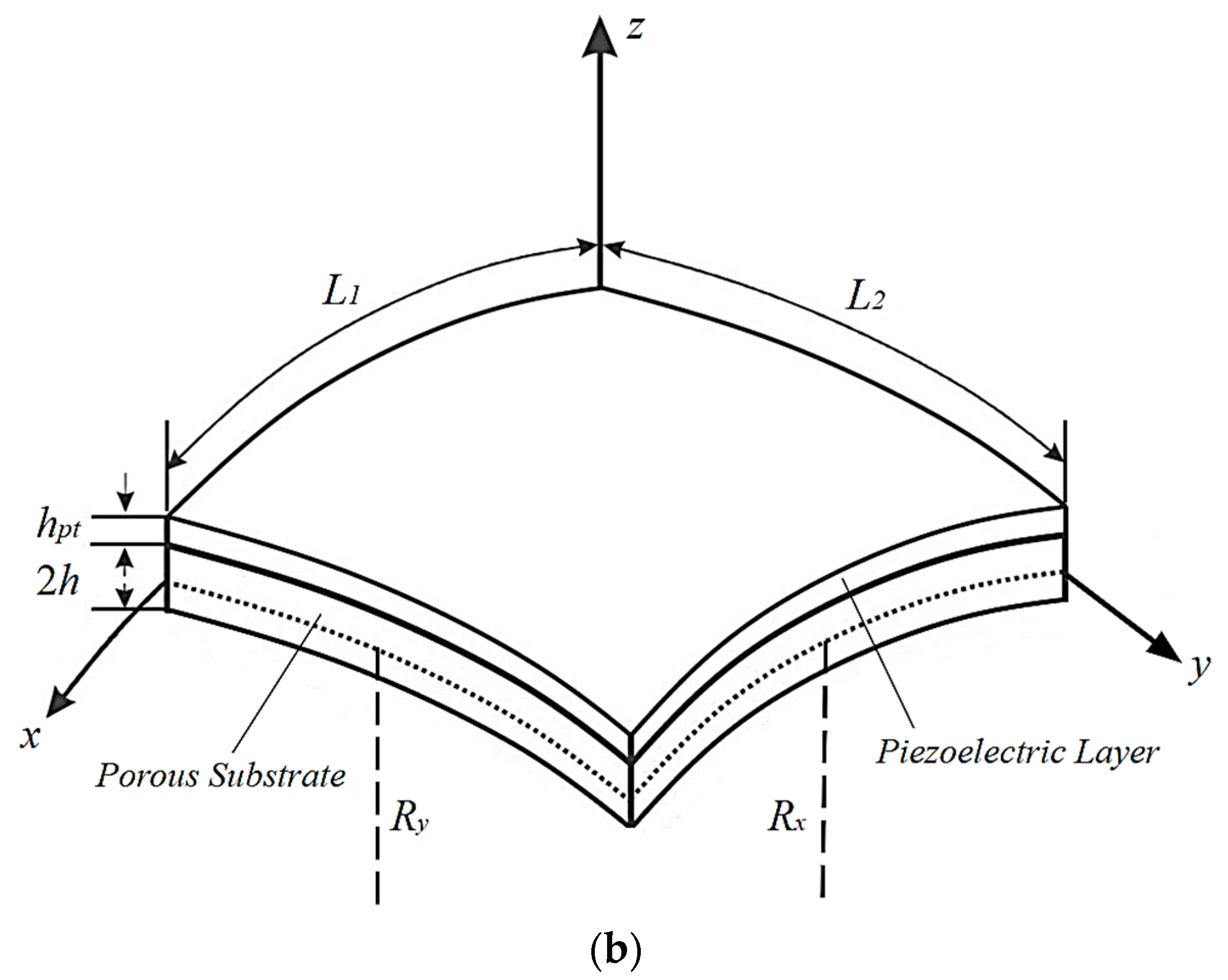
The layouts of the bimorph and unimorph doubly curved panels made of porous media and piezoelectric materials are depicted in Figure 1a,b, respectively. As is shown, the bimorph structure is composed of a porous core integrated with two identical thickness-poled piezoelectric layers (hpt = hpb), while the unimorph panel has only one piezoelectric layer (hpb = 0) mounted on the top surface of its substrate. Both the panels have arc lengths L1 and L2, and Rx and Ry are the curvature radii of the mid-surface of the substrate layer. Also, 2h is the thickness of the substrate and hpt and hpb are corresponded to the top and bottom piezoelectric layers’ thickness, respectively. To extract the mathematical formulations, the origin of the coordinate system (x, y, z) is located on the middle-surface of the substrate layer.
It should be noted that in both bimorph and unimorph sandwich structures considered in this study, the piezoelectric layers and the substrate are assumed to be perfectly bonded together with an adhesive layer of negligible thickness, therefore there is no relative displacement between the layers of the sandwich panel. This assumption has been considered in a wide range of published works in this field [15,50,51,52,53,54,56,57,58,59,60,61,62,63,64,65,66].
It is assumed that the material properties such as elasticity modulus and mass density in the host layer are varied through the thickness direction due to the existence of internal pores. Various rules are presented in the literature to model the variation of mechanical properties in porous materials [30,35,36,37,38,39,40,65,66,67]. However, the effective Young’s modulus E(z), shear elastic modulus G(z) and mass density ρ (z) within the porous substrate are considered to have the following nonlinear variations along the thickness [67]:
E ( z ) = E 1 ( 1 e cos ( π ( z + h ) 4 h ) ) G ( z ) = G 1 ( 1 e cos ( π ( z + h ) 4 h ) ) ρ ( z ) = ρ 1 ( 1 e cos ( π ( z + h ) 4 h ) ) e = 1 E 0 E 1 = 1 G 0 G 1 e = 1 ρ 0 ρ 1 = 1 1 e ,
where subscripts “1” and “0” show the properties corresponding to the top and bottom surfaces of the host layer, respectively.
The relationship between shear modulus and Young’s modulus is E(z) = 2G(z)(1 + ν ) in which ν is the Poisson’s ratio. Moreover, e (0 e < 1) denotes the porosity volume fraction for the Young’s modulus and e’ is the dimensionless parameter of effective mass density. According to relations (1), the maximal and minimal values of mechanical properties occur at the top and bottom surfaces of the substrate layer, respectively.

2.2. Constitutive Equations and Electric Potential

Piezoelectrics are intelligent materials, which convert electrical and mechanical excitations to each other. In this study, the piezoelectric layers are assumed to be made of transversely piezoelectric materials in which mechanical stresses and electrical displacements are modeled as a combination of electrical and mechanical variables. In addition, porous media are isotropic materials within which their stress–strain relations simply obey Hook’s law [67]. Thus, the constitutive equations for porous core and piezoelectric layers are taken to be [60]:
{ σ } = [ C ] s { ε }
{ σ } = [ C ] p { ε } [ e ] T { E } ,
{ D } = [ e ] { ε } [ Ξ ] { E }
where superscripts “s” and “p” are introduced for the variables corresponded to the substrate and piezoelectric layers of the smart porous panel, respectively; { σ } and { ε } are the mechanical stress and strain tensors, {D} is the electric displacement and {E} represents the electric field within piezoelectric layers. [C], [e] and [ Ξ ] represent matrices of elastic constants, electromechanical coupling and dielectric permittivity, respectively.
The relation between electric field ( E ) and potential ( ϕ ) in piezoelectric layers is defined as follows:
E = ϕ ,
in which shows the gradient vector.
Furthermore, it is assumed that the electric potential has nonlinear variations with respect to z-coordinate [57]. In relations 4(a) and 4(b), the electric potential functions are given for the top and bottom piezoelectric layers, respectively:
ϕ ( x , y , z , t ) = A ( x , y , t ) z + B ( x , y , t ) + ( 1 ( 2 z 2 h h p t h p t ) 2 ) ϕ 0 ( x , y , t ) ,
ϕ ( x , y , z , t ) = C ( x , y , t ) z + D ( x , y , t ) + ( 1 ( 2 z 2 h h p b h p b ) 2 ) ϕ 0 ( x , y , t ) ,
where function ϕ 0 is the electric potential function in the mid-surface of piezoelectric layers; A, B, C and D are four unknown functions, which will be obtained by satisfying the electrical boundary conditions.
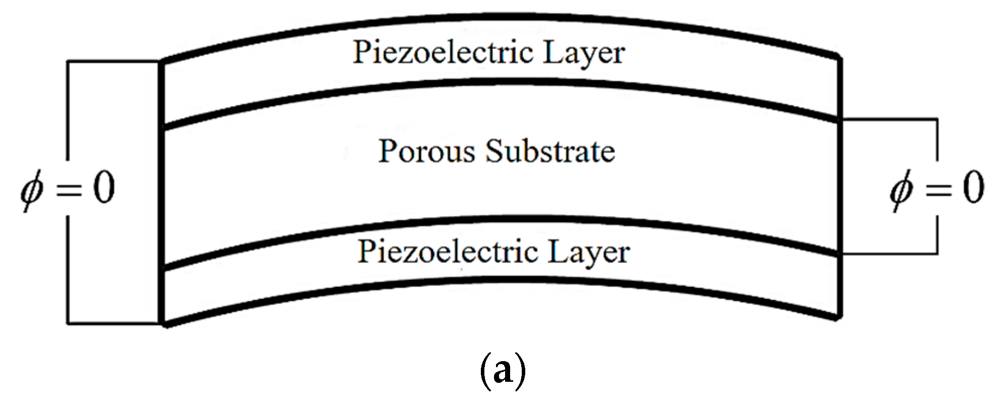
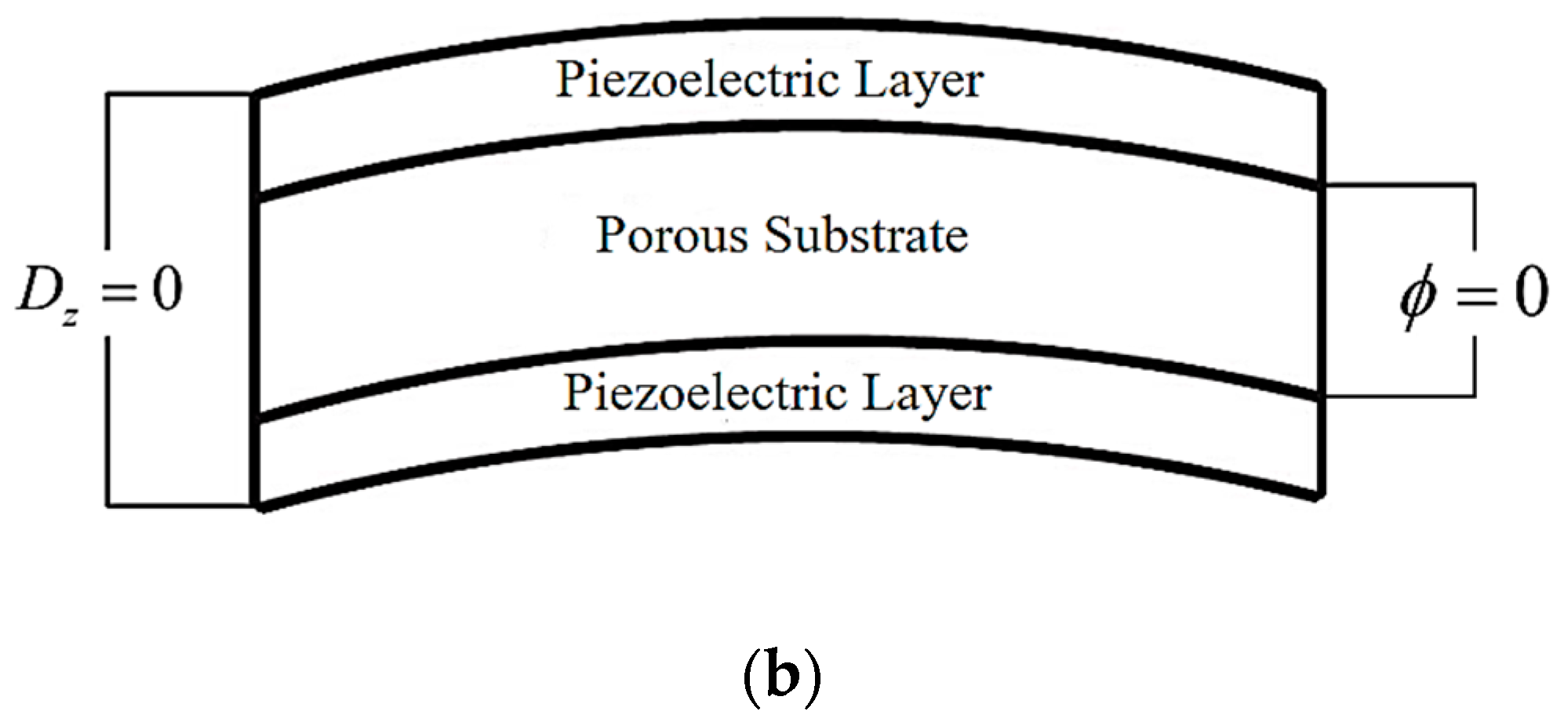
Two common electrical conditions SC and OC are considered for piezoelectric layers, as shown in Figure 2.
These conditions are further discussed in the following:
(I) SC (short circuit):
ϕ = 0   at   z = ± h ,   z = ( h + h p b ) ,   z = + ( h + h p t ) ,
applying relations (5) to Equations (4) leads to:
A = B = C = D = 0 ,
(II) OC (open circuit):
ϕ = 0   at   z = ± h D z = 0   at   z = ( h + h p b ) ,   z = + ( h + h p t ) ,
By imposing the above conditions in Relations (4), the functions A, B, C, and D are obtained as:
B = A h D = + C h A = e 31 Ξ 33 ( u 0 , x + v 0 , y + ( h + h p t ) [ ψ x , x + ψ y , y ] + ( 1 R x + 1 R y ) w 0 ) + 4 ϕ 0 h p t C = e 31 Ξ 33 ( u 0 , x + v 0 , y ( h + h p b ) [ ψ x , x + ψ y , y ] + ( 1 R x + 1 R y ) w 0 ) 4 ϕ 0 h p b ,

2.3. Electromechanically Coupled Equations of Motion

Based on FSDT, the components of the mechanical displacement field ( u , v , w ) at any point of the hybrid panel are defined as follows [68]:
u ( x , y , z , t ) = u 0 ( x , y , t ) + z ψ x ( x , y , t ) v ( x , y , z , t ) = v 0 ( x , y , t ) + z ψ y ( x , y , t ) w = w 0 ( x , y , t ) ,
where u 0 , v 0 , and w 0 are the mechanical displacements of any point of the shell mid-surface along the orthogonal curvilinear coordinates. The functions ψ x and ψ y represent the rotations of normal to mid-plane about y and x axes, respectively, and t is the time variable.
Considering linear relations of strain-displacement as well as Equation (9), the following expressions are given for the components of mechanical strain field [68]:
ε x x = u 0 , x + z ψ x , x + w 0 / R x ε y y = v 0 , y + z ψ y , y + w 0 / R y ε z z = 0 γ x y = u 0 , y + v 0 , x + z ( ψ x , y + ψ y , x ) γ x z = ψ x + w 0 , x u 0 / R x γ y z = ψ y + w 0 , y v 0 / R y ,
where and hereafter, a comma shows partial differentiation versus the corresponding coordinates. As seen from Relation (10), it is assumed that the transverse shear deformation is constant between layers of the panel, thus the sandwich panels are modeled as continuous and uniform systems within its volume.
Employing Hamilton’s principle, the following five equations of motion are obtained based on the FSDT for doubly curved shells [68]:
N x x , x + N x y , y + Q x z / R x = I 0 u ¨ 0 + I 1 ψ ¨ x N x y , x + N y y , y + Q y z / R y = I 0 v ¨ 0 + I 1 ψ ¨ y M x x , x + M x y , y Q x z = I 1 u ¨ 0 + I 2 ψ ¨ x M x y , x + M y y , y Q y z = I 1 v ¨ 0 + I 2 ψ ¨ y Q x z , x + Q y z , y N x x / R x N y y / R y = I 0 w ¨ 0 ,
where the stress resultants Nij, Mij and Qij, and the mass inertias Iij are defined as follows:
( N x x , N x y , N y y ) = h h p b + h + h p t ( σ x x , σ x y , σ y y ) d z ( M x x , M x y , M y y ) = h h p b + h + h p t ( σ x x , σ x y , σ y y ) z d z ( Q x z , Q y z ) = h h p b + h + h p t ( σ x z , σ y z ) d z ( I 0 , I 1 , I 2 ) = h h p b + h + h p t ρ ( z ) ( 1 , z , z 2 ) d z ,
With the help of the Maxwell’s equation about electrostatics [60], the last equation of motion can be derived as follows:
β 1 ( ψ x , x + ψ y , y + 2 w 0 u 0 , x R x v 0 , y R y ) + β 2 ( ψ x , x + ψ y , y ) + β 3 φ 0 + β 4 2 φ 0 + η 1 ( 2 ( u 0 , x ) + 2 ( v 0 , y ) + ( 1 R x + 1 R y ) 2 w 0 ) + η 2 ( 2 ( ψ x , x ) + 2 ( ψ y , y ) ) = 0 ,
where 2 (…) is the Laplace operator and coefficients β i (i = 1, 2, 3, 4) and η j (j = 1, 2) are defined for both the SC and OC electrical conditions, in Relations (A1) to (A3) of the Appendix A.

2.4. Solution Procedure

To derive the electromechanical governing equations, the stress resultants are written in terms of mechanical displacement components ( u 0 , v 0 , w 0 ) and electric potential ( ϕ 0 ), through substitution of Relations (2) and (10) into Relations (12), as follows:
N x x = a 11 u 0 , x + a 12 v 0 , y + b 11 ψ x , x + b 12 ψ y , y + p 11 w 0 + β 5 ϕ 0 N y y = a 12 u 0 , x + a 11 v 0 , y + b 12 ψ x , x + b 11 ψ y , y + p 11 w 0 + β 5 ϕ 0 N x y = a 66 ( u 0 , y + v 0 , x ) + b 66 ( ψ x , y + ψ y , x ) M x x = b 11 u 0 , x + b 12 v 0 , y + d 11 ψ x , x + d 12 ψ y , y + q 11 w 0 + β 6 ϕ 0 M y y = b 12 u 0 , x + b 11 v 0 , y + d 12 ψ x , x + d 11 ψ y , y + q 11 w 0 + β 6 ϕ 0 M x y = b 66 ( u 0 , y + v 0 , x ) + d 66 ( ψ x , y + ψ y , x ) Q x z = a 55 ( ψ x + w 0 , x u 0 / R x ) + β 7 ϕ 0 , x + β 8 ( u 0 , x x + v 0 , y x + w 0 , x / R x + w 0 , x / R y ) + β 9 ( ψ x , x x + ψ y , y x ) Q y z = a 55 ( ψ y + w 0 , y v 0 / R y ) + β 7 ϕ 0 , y + β 8 ( u 0 , x y + v 0 , y y + w 0 , y / R x + w 0 , y / R y ) + β 9 ( ψ x , x y + ψ y , y y ) ,
where the constant coefficients aij, bij, dij, pij, qij and β i (i = 5, 6, 7, 8, 9) are given in Relations (A4) to (A8) of the Appendix A.
Introducing Relations (14) into Equations (11) leads to the following, highly coupled partial differential equations:
( a 11 + β 8 R x ) u 0 , x x + a 66 u 0 , y y + ( a 12 + a 66 + β 8 R x ) v 0 , x y + ( b 11 + β 9 R x ) ψ x , x x + b 66 ψ x , y y + ( b 12 + b 66 + + β 9 R x ) ψ y , x y a 55 R x 2 u 0 + a 55 R x ψ x + ( p 11 + a 55 R x + β 8 R x 2 + β 8 R x R y ) w 0 , x + ( β 5 + β 7 R x ) ϕ 0 , x = I 0 u ¨ 0 + I 1 ψ ¨ x ,
( a 12 + a 66 + β 8 R y ) u 0 , x y + ( a 11 + β 8 R y ) v 0 , y y + a 66 v 0 , x x + ( b 12 + b 66 + β 9 R y ) ψ x , x y + ( b 11 + β 9 R y ) ψ y , y y + b 66 ψ y , x x a 55 R y 2 v 0 + a 55 R y ψ y + ( p 11 + a 55 R y + β 8 R y + β 8 R x R y ) w 0 , y + ( β 5 + β 7 R y ) ϕ 0 , y = I 0 v ¨ 0 + I 1 ψ ¨ y ,
( b 11 β 8 ) u 0 , x x + b 66 u 0 , y y + ( b 12 + b 66 β 8 ) v 0 , x y + ( d 11 β 9 ) ψ x , x x + d 66 ψ x , y y + ( d 12 + d 66 β 9 ) ψ y , x y + a 55 R x u 0 a 55 ψ x + ( q 11 a 55 β 8 R x β 8 R y ) w 0 , x + ( β 6 β 7 ) ϕ 0 , x = I 1 u ¨ 0 + I 2 ψ ¨ x ,
( b 12 + b 66 β 8 ) u 0 , x y + ( b 11 β 8 ) v 0 , y y + b 66 v 0 , x x + ( d 12 + d 66 β 9 ) ψ x , x y + ( d 11 β 9 ) ψ y , y y + d 66 ψ y , x x + a 55 R y v 0 a 55 ψ y + ( q 11 a 55 β 8 R x β 8 R y ) w 0 , y + ( β 6 β 7 ) ϕ 0 , y = I 1 v ¨ 0 + I 2 ψ ¨ y ,
( a 55 + β 8 R x + β 8 R y ) 2 w 0 + β 7 2 ϕ 0 ( a 11 R x + a 12 R y + a 55 R x ) u 0 , x ( a 12 R x + a 11 R y + a 55 R y ) v 0 , y ( b 11 R x + b 12 R y ) ψ x , x ( b 12 R x + b 11 R y ) ψ y , y + a 55 ψ x , x + a 55 ψ y , y ( p 11 R x + p 11 R y ) w 0 ( β 5 R x + β 5 R y ) ϕ 0 + β 8 2 u 0 , x + β 8 2 v 0 , x + β 9 2 ψ x , x + β 9 2 ψ y , y = I 0 w ¨ 0 ,
To solve Maxwell’s equation (13) and the dynamic Equations (15), mechanical and electrical boundary conditions are needed. In this study, simply supported mechanical boundary conditions are assumed for all the four edges of the doubly curved panel. Also, it is considered that all the edges are electrically grounded to zero potential for both bimorph and unimorph structures. With the help of the variational method and divergence theorem, these conditions can be determined as follows:
v 0 = ψ y = w 0 = N x x = M x x = ϕ 0 = 0 at   x = 0 ,   x = L 1 , u 0 = ψ x = w 0 = N y y = M y y = ϕ 0 = 0 at   y = 0 ,   y = L 2 ,
Here, the Navier’s method is employed to have an analytical solution. Based on this approach, the unknown mechanical displacement components u 0 , v 0 , w 0 , ψ x and ψ x as well as the electric potential ϕ 0 are assumed to have the following trigonometric expansions:
u 0 ( x , y , t ) = m = 1 n = 1 cos ( μ m x ) sin ( μ n y ) η m n u 0 ( t ) v 0 ( x , y , t ) = m = 1 n = 1 sin ( μ m x ) cos ( μ n y ) η m n v 0 ( t ) w 0 ( x , y , t ) = m = 1 n = 1 sin ( μ m x ) sin ( μ n y ) η m n w 0 ( t ) ψ x ( x , y , t ) = m = 1 n = 1 cos ( μ m x ) sin ( μ n y ) η m n ψ x ( t ) ψ y ( x , y , t ) = m = 1 n = 1 sin ( μ m x ) cos ( μ n y ) η m n ψ y ( t ) ϕ 0 ( x , y , t ) = m = 1 n = 1 sin ( μ m x ) sin ( μ n y ) η m n ϕ 0 ( t ) ,
Moreover, relations (17) satisfy the boundary conditions (16). In equations (17), the parameters μ m and μ n are equal to m π / L 1 and n π / L 2 , respectively, and m and n are number of half-waves through x and y directions, respectively. By assuming a harmonic motion for the system, the functions η m n ( t ) can be defined as follows:
{ η m n u 0 η m n v 0 η m n w 0 η m n ψ x η m n ψ y η m n ϕ 0 } = { S m n u 0 S m n v 0 S m n w 0 S m n ψ x S m n ψ y S m n ϕ 0 } e i ω t ,
where i = 1 and ω is the natural frequency of the smart doubly curved panel.
The substitution of Relations (17) and (18) into Equations (13) and (15) results in the following eigenproblem:
( [ k 11 k 12 k 13 k 14 k 15 k 16 k 21 k 22 k 23 k 24 k 25 k 26 k 31 k 32 k 33 k 34 k 35 k 36 k 41 k 42 k 43 k 44 k 45 k 46 k 51 k 52 k 53 k 54 k 55 k 56 k 61 k 62 k 63 k 64 k 65 k 66 ] ω 2 [ m 11 m 12 m 13 m 14 m 15 m 16 m 21 m 22 m 23 m 24 m 25 m 26 m 31 m 32 m 33 m 34 m 35 m 36 m 41 m 42 m 43 m 44 m 45 m 46 m 51 m 52 m 53 m 54 m 55 m 56 m 61 m 62 m 63 m 64 m 65 m 66 ] ) { S m n u 0 S m n v 0 S m n w 0 S m n ψ x S m n ψ y S m n ϕ 0 } = { 0 0 0 0 0 0 } ,
where [k] and [m] are the stiffness and inertia matrices, respectively.
The solution of the eigenproblem (19) allows to extract the eigenfrequencies of the system. In the next section, the natural frequencies are presented for bimorphs and unimorphs, with a wide range of parameters as well as various geometries.

3. Numerical Results and Discussion

3.1. Verification Studies

Three validation examples are presented to assess the accuracy of the aforementioned procedure and formulation by comparing the results just obtained with those available in literature. Due to slight variation of Poisson’s ratio along the thickness of the substrate layer, its value is considered to be constant and equal to 0.3. The parameter Hp in the following tables and figures represents the total thickness of piezoelectric layers, which is equal to Hp = hpb + hpt and Hp = hpt for bimorph and unimorph structures, respectively, as reported in Figure 1. In Table 1, SC and OC fundamental frequencies are compared with their counterparts in [60], for a bimorph doubly curved shell, which consisted of a homogenous core surrounded by two identical PZT-4 layers. In the study of Sayyaadi and Farsangi [60], the authors considered shell through-thickness kinematics based on the higher-order shear deformation theory and used a quadratic variation for the electric potential distribution in piezoelectric layers.
To verify the accuracy of this study to predict natural frequencies of higher vibrational modes, the first ten SC natural frequencies of an isotropic plate with piezoelectric layers are computed and compared with those predicted by [61,64,69], as listed in Table 2.
The last comparative study is presented in Table 3 for the SC fundamental frequencies of the present formulations and those reported in [59], for bimorph and unimorph structures having different geometries. In [59], the electric potential distribution within piezoelectric layers is considered as function of z coordinate only, whereas in the current study it is modeled by a function of all three coordinates. However, since various mechanical displacement models and electric potential distributions are employed in the current study and the above-mentioned references, some slight differences are observed among the results. Nevertheless, it is evident from Table 1, Table 2 and Table 3 that the results of the present exact solution based on FSDT are in close agreement with the ones reported in the literature.

3.2. New Results and Discussion

In the following, new results are presented for SC and OC eigenfrequencies of porous bimorph and unimorph panels having spherical (Rx, Ry > 0), hyperbolic paraboloidal (Rx > 0, Ry < 0), cylindrical (Rx 0, Ry ) and plate (Rx , Ry ) geometries. Aluminum (E = 70 GPa, ρ = 2700 kg/m3) and PZT-5H (properties can be found in [59]) are assumed as the materials of the substrate and piezoelectric layers, respectively. To be able of making comparisons among various geometries of bimorph and unimorph panels, the same volume of materials is considered for all the considered cases.
In Table 4, for length ratio L1/L2 = 1, thickness-length ratio 2h/L1=0.05 and thickness ratio Hp/2h = 0.2, the SC and OC resonance frequencies are listed for porous bimorph and unimorph panels having different geometries in constant volume. The results show that increasing the porosity parameter causes a decrease in the value of natural frequency regardless of the type of smart panel (i.e., bimorph or unimorph) as well as the electrical condition. This behavior is observed for all the panel geometries and structures studied here. Actually, it is due to the fact that when the porosity increases, the structural stiffness drops, which leads to reduce the eigenfrequencies. Furthermore, it is seen that for the same materials composition and the constant volume, various geometries exhibit different natural frequencies in such a way that the highest values are related to spherical shells followed by cylindrical, plate and hyperbolic paraboloidal panels. Also, the table illustrates that both bimorph and unimorph structures have higher frequencies in OC condition in comparison with when the piezoelectric layers are kept at SC condition.
Fundamental natural frequencies of different bimorphs and unimorphs in SC condition are depicted in Table 5 and Table 6 for wide range of parameters including 2h/L1, Hp/2h and Rx/L1. These tables indicate that by increasing the shell curvature, the eigenfrequencies decrease for all the studied curved panels (i.e., spherical and cylindrical shells) except for hyperbolic paraboloidal shell in which the natural frequency significantly rises, as the radius increases. In addition, it seems that increasing the thickness of the substrate layer raises the natural frequency in such a manner that this growth is more remarkable for hybrid shells with higher values of Rx/L1. For example, when Rx/L1 = 1, the natural frequency of bimorph spherical shell has a growth of 11.5% due to increasing the thickness-length ratio (2h/L1) from 0.1 to 0.15, while the value of this growth is about 42.5% when Rx/L1 = 10, as seen in Table 5. Similar behaviors can be observed for other geometries. Moreover, the tables reveal that the natural frequencies for bimorph panels are usually greater than those of unimorphs in same composition of materials, owing to asymmetry of unimorph structures.
To discuss the observed behaviors of resonance frequencies for the SC and OC electrical conditions, the fundamental frequencies of various porous hybrid structures are listed in Table 7, for different values of Hp/2h. In the second and fifth columns of this table, the listed frequencies are quantified by eliminating the electrical effect of piezoelectric layers (i.e., by setting the electromechanical coupling coefficients eij = 0 [57]) to show only the mechanical effect of piezoelectric layers on the results. By inspecting the values in the table, one can realize that the electrical effect in SC condition is negligible, whilst it plays a key role in the OC condition to increase the value of eigenfrequencies. It does mean that the observed changes in natural frequency, due to mounting the SC piezoelectric layers on the substrate, are associated with the stiffening effect of piezoelectric layers only, whereas the frequencies are significantly influenced by the electrical part (in addition to mechanical part), when keeping piezoelectric layers in OC condition. This behavior could be ascribed to various electric potential distributions in SC and OC conditions, which are given in relation (4). Furthermore, both the SC and OC natural frequencies increase by raising the thickness ratio Hp/2h, regardless of the type of structure. It is also observed that in the case of spherical porous smart panel, the electrical effect associated with the OC piezoelectric layer is more remarkable for unimorphs compared to that of bimorphs, while the opposite result is seen for other geometries.
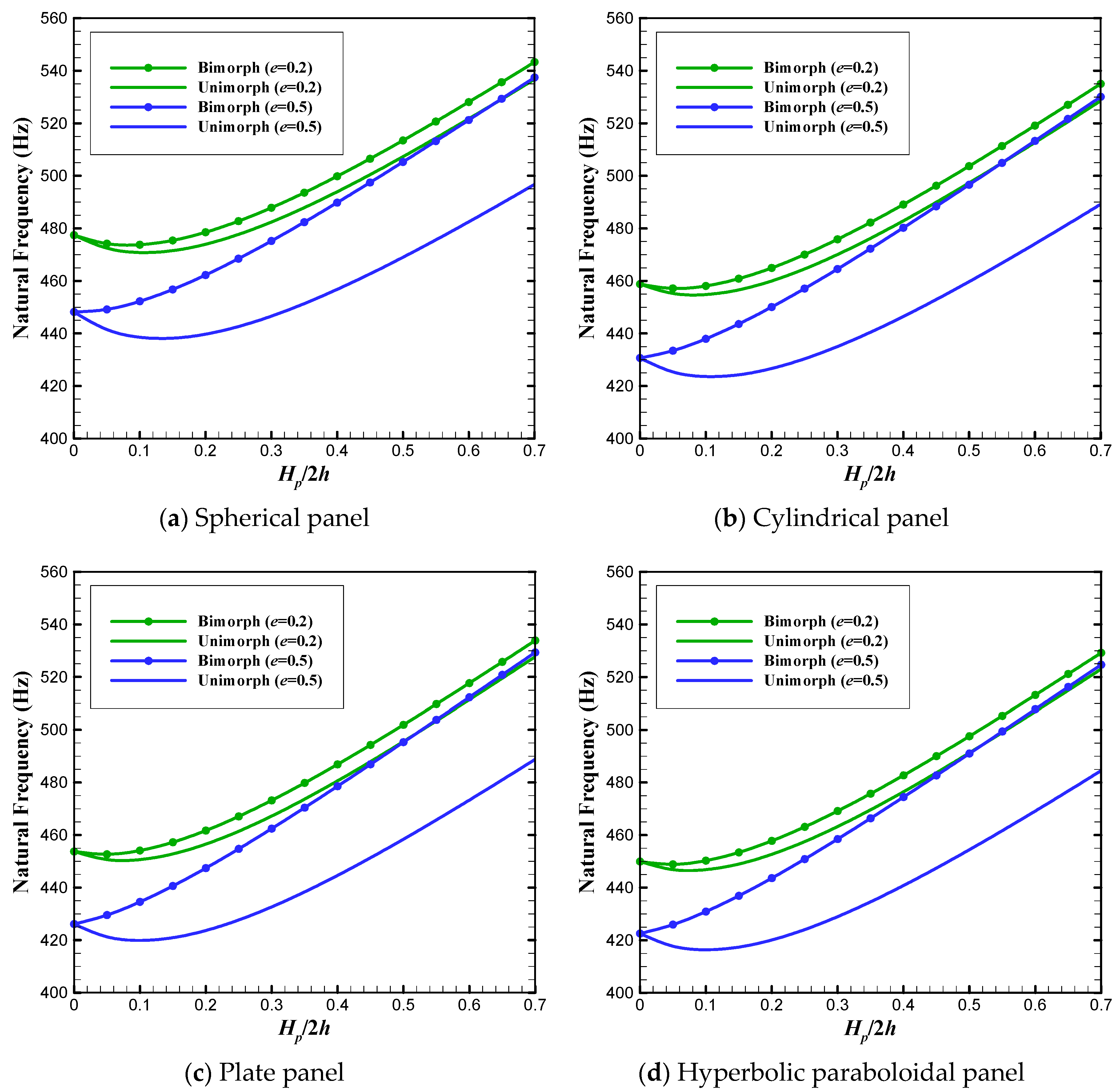
In Figure 3a–d, for different values of porosity parameter namely 0.2 and 0.5, variations of the SC fundamental frequency with respect to Hp/2h are plotted. Regardless of the panel geometry, it seems that by increasing the value of Hp/2h, the shell natural frequencies considerably increase, in such a way that this growth is more remarkable for bimorph structures. As is obvious, at any fixed value of Hp/2h, the frequencies of bimorphs are higher than those of unimorphs and this difference increases by raising the porosity parameter. In addition, for the bimorph panels, the curves corresponded to e = 0.5 have greater slopes in comparison with the ones associated with e = 0.2, which means that the natural frequency of bimorph panels with higher coefficient of porosity are more influenced by changing the thickness ratio Hp/2h, whereas the curves related to unimorph structures seem to be parallel for the studied values of e. By investigating the numerical results, similar trends can be observed for the OC electrical condition.
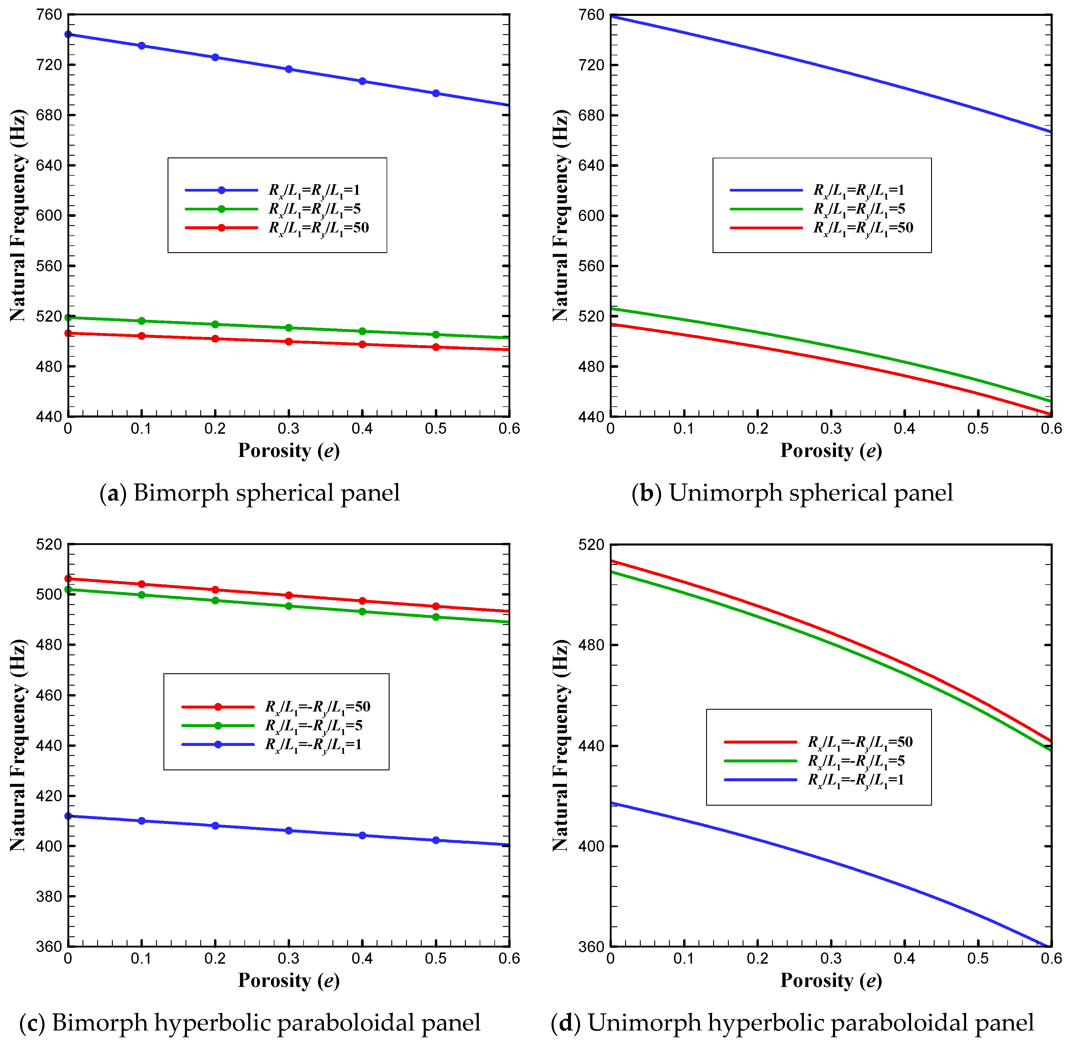
Figure 4a–d show the effect of changes in the shell curvature on variation of the SC natural frequencies of smart doubly curved panels, with respect to the porosity parameter. As observed, changing the shell radius significantly affects the natural frequency. It is seen that by increasing the value of curvature, the fundamental frequency of spherical shells decreases, while the opposite trend is seen for hyperbolic paraboloidal shells. Moreover, those figures reveal that changing the porosity parameter has a greater effect on the natural frequencies of unimorph panels with respect to bimorphs.
In Figure 5a,b, variations of the first two resonance frequencies of spherical smart shells with respect to Rx/L1 are plotted for the SC and OC electrical conditions. Again, it is seen that by increasing the shell curvature, the frequencies of both vibrational modes decrease. When the value of Rx/L1 increases from 1 to around 3, the frequencies greatly reduce, while by further increasing the curvature, very smooth decreasing trends are observed for both Mode 1 and Mode 2.
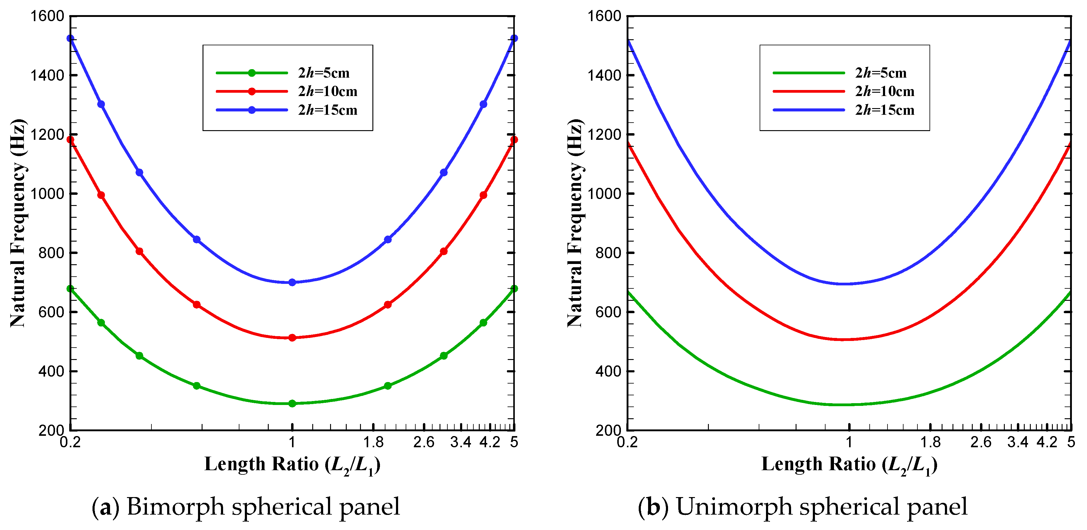
Parameters L1 and L2 have a direct influence on the eigenfrequencies. By changing the length ratio in constant surface area, the variation of resonance frequency versus L2/L1 is shown in Figure 6 for spherical porous bimorphs and unimorphs in SC electrical condition. The value of L2/L1 is considered to change from 1/5 to 5, while the surface area is kept constant (equal to L1 × L2 = 1 m2). It is observed that for any considered value of the substrate thickness, the minimum frequency is achieved at L2/L1 = 1, and the frequency response has symmetric behavior around L2/L1 = 1. This behavior originates from the induced increase in the panel stiffness due to declining/raising the length ratio. For other geometries and the OC electrical condition, similar results can be obtained.
To gain a deeper insight into the effect of piezoelectric layers on the frequency response of the system, the parameter θ representing the relative difference in frequency is defined as follows:
θ = ω | With   Piezoelectric   Layers ω | Without   Piezoelectric   Layers ω | Without   Piezoelectric   Layers × 100   ,
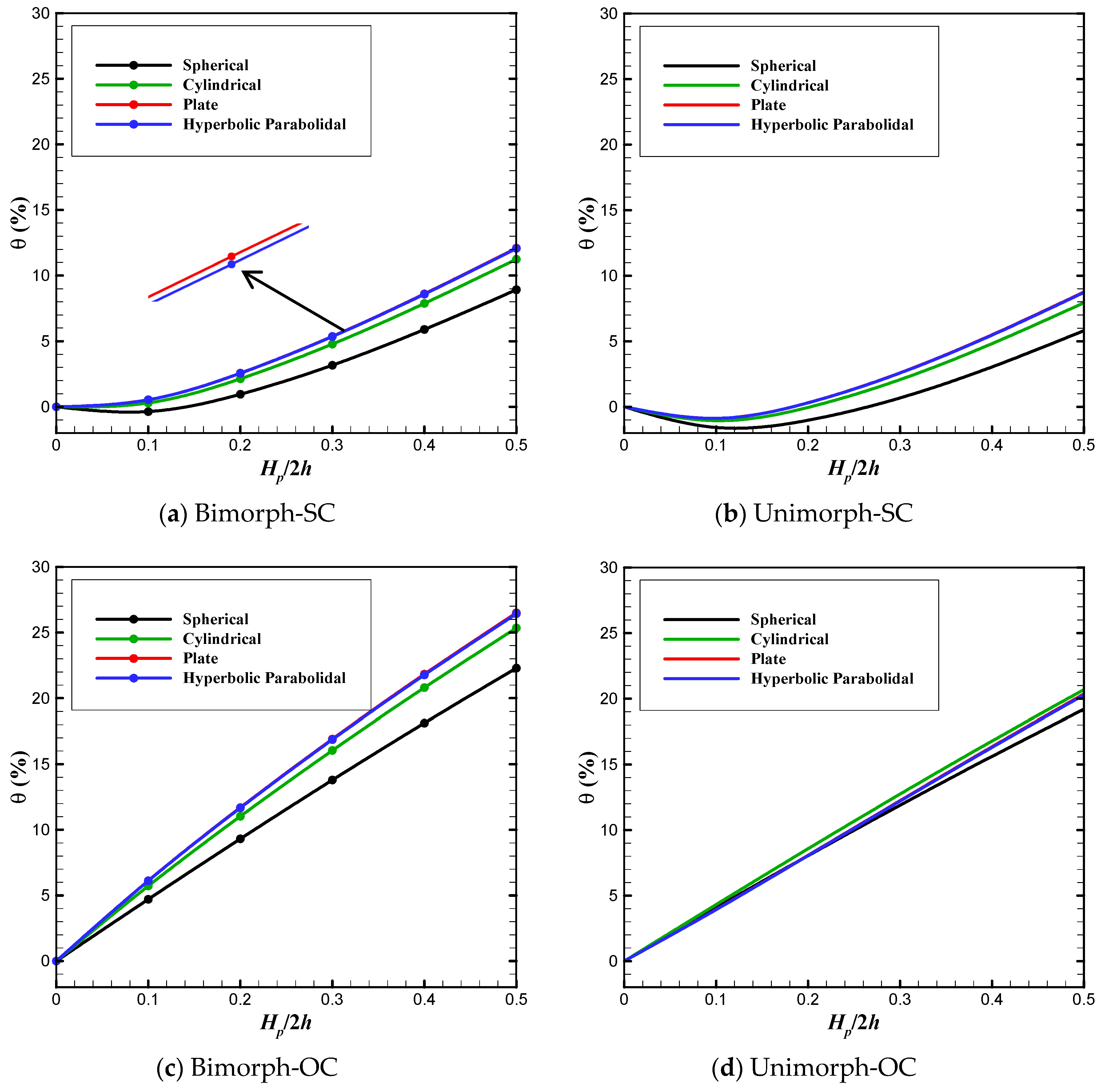
For smart panels with L1/L2 = 1, 2h/L1 = 0.1, Rx/L1 = Ry/L1 = 5 and e = 0.3, the variation of θ with respect to Hp/2h is plotted in Figure 7a–d. Those figures show that, at a fixed value of the thickness ratio, the magnitude of θ is the most for both plate and hyperbolic paraboloidal panels and the least for spherical shells irrespective of the electrical condition. This does mean that the addition of piezoelectric layers to the porous substrate has quantitatively different effects on the frequencies of panels with various geometries. Moreover, it seems that in the SC condition, by adding piezoelectric layers, the natural frequencies of coupled panels initially decrease till Hp/2h = 0.15, and subsequently increase as the value of Hp/2h rises. This descending/ascending trend is regarded to the changes in the effective mass density and structural stiffness of the coupled smart panels due to increasing the thickness ratio. Differently, since the electrical effect of piezoelectric layers plays a significant role in the growth of OC frequencies, only ascending trends are seen for the variation of eigenfrequencies from Hp/2h = 0 to Hp/2h = 0.5 in OC condition. In addition, it is clear that for the same thickness of piezoelectric layers, the value of θ for bimorphs is greater than that of unimorph panels, in both SC and OC conditions.
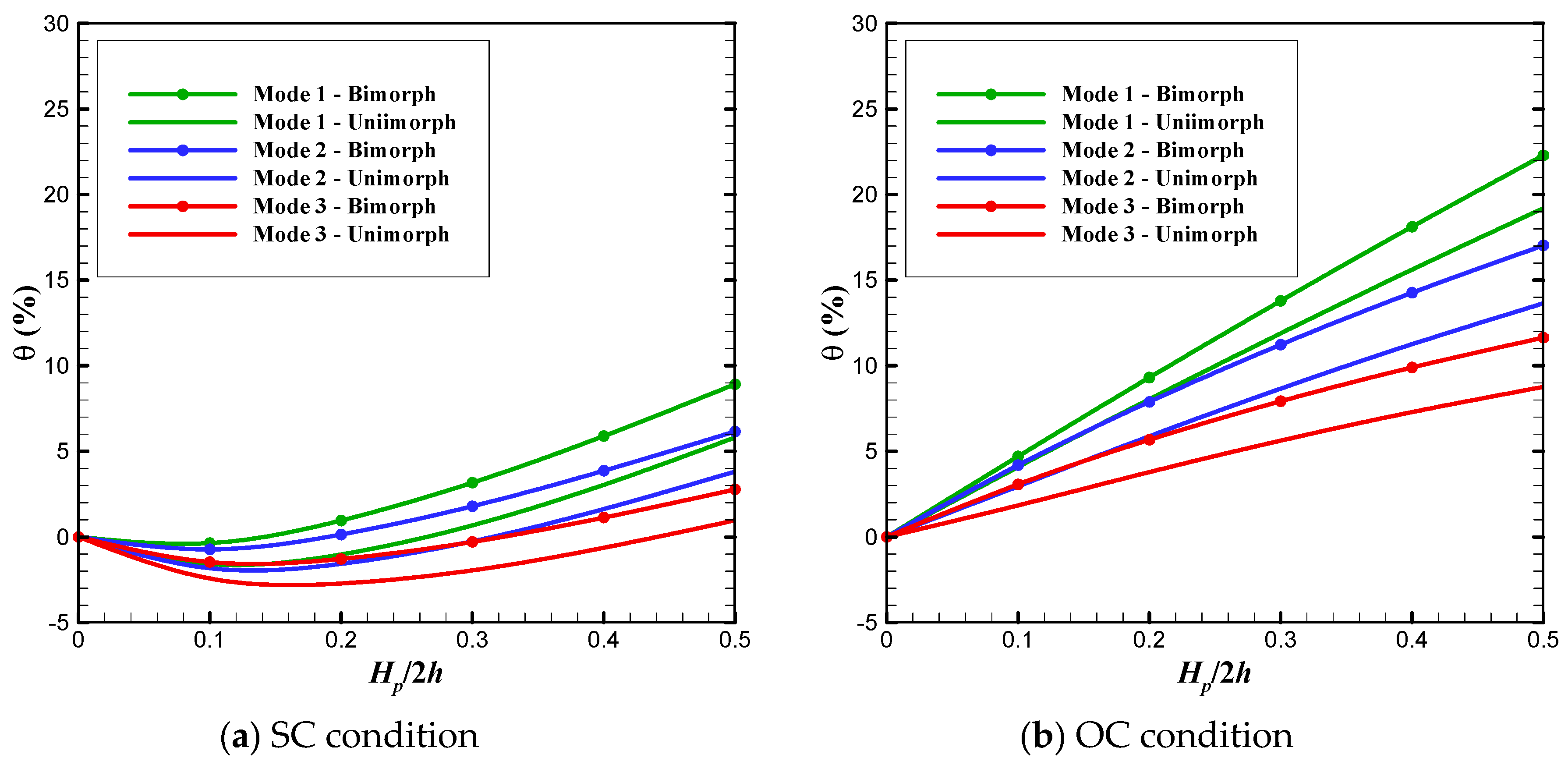
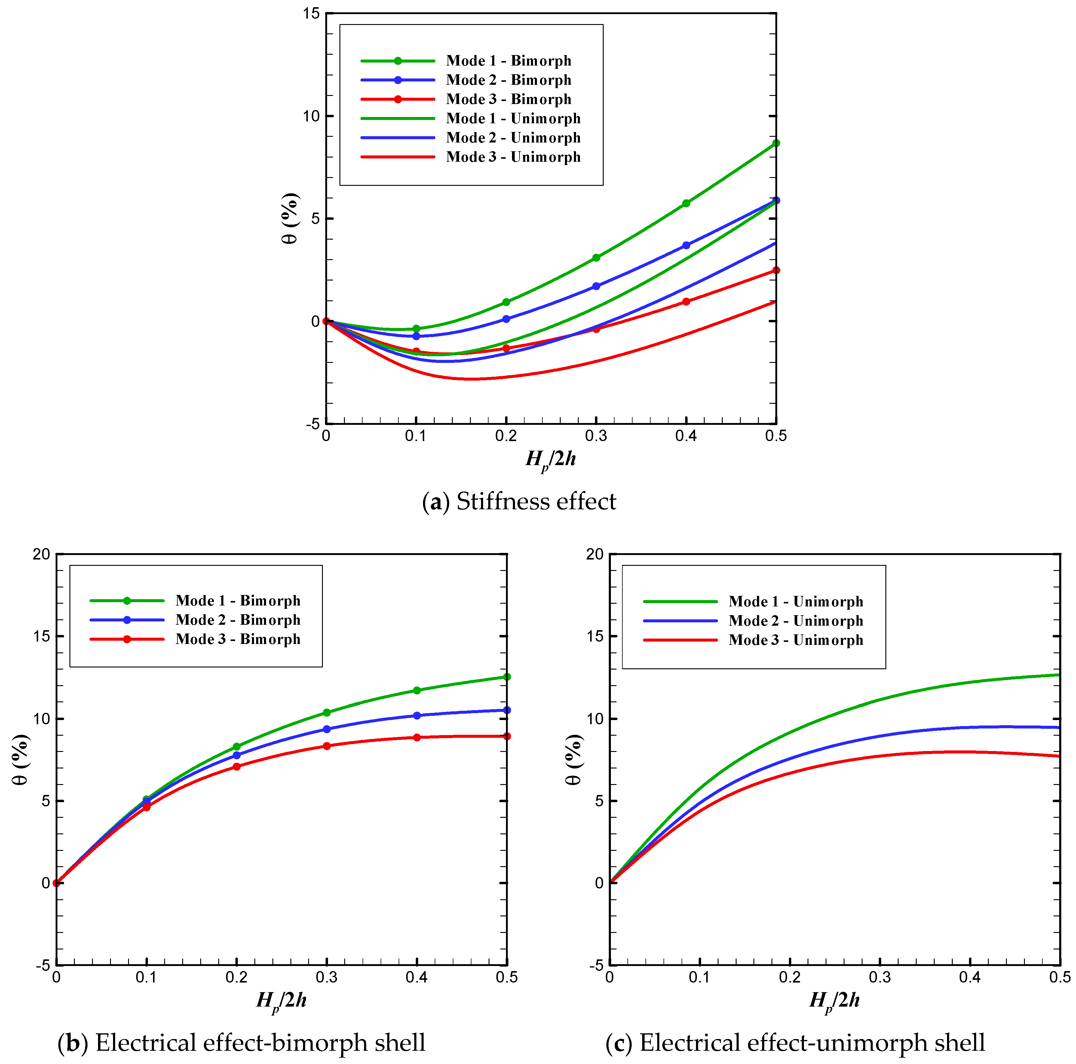
To investigate the influence of electrical circuits (i.e., SC and OC), thickness ratio Hp/2h and electrical and mechanical effects of piezoelectric layers on frequencies of various vibration modes, Figure 8 and Figure 9 are plotted for spherical shells with 2h/L1 = 0.1, L1/L2 = 1 and Rx/L1 = Ry/L1 = 5. Particularly in Figure 8, the variation of θ with respect to Hp/2h is presented for both spherical bimorphs and unimorphs under SC and OC conditions. In addition, by setting eij = 0, the stiffness effect of piezoelectric layers on the first three frequencies is examined in Figure 9a, while Figure 9b,c show the variation of Ω versus thickness ratio Hp/2h, in which the parameter Ω (defined in Table 7) is related to electrical effect of piezoelectric layers. From Figure 9, it can be simply observed that the natural frequencies associated with higher vibration modes are less influenced by changing the value of Hp/2h in comparison with the fundamental frequency. Moreover, the change in the value of natural frequency due to the effects of both electrical and mechanical parts of piezoelectric layers is the greatest for Mode 1 and the least for Mode 3, as is obvious in Figure 9.
In the following, the parameter Γ is defined to investigate the sensitivity of various vibration modes to the variation of porosity:
Γ = ω | Shell   with   Porosity ω | Shell   without   Porosity ω | Shell   without   Porosity × 100   ,
Figure 10 represents the variation of Γ with respect to e for the first three resonance frequencies of spherical bimorph shells under SC and OC conditions. It is seen that in both SC and OC conditions, all the three eigenfrequencies of Mode 1, Mode 2 and Mode 3 are linearly reduced by increasing the value of porosity in such a way that the frequencies of higher modes are more sensitive to the porosity parameter. In addition, it seems that changing the value of porosity has more effect on SC frequencies compared to OC ones.

4. Conclusions

The electromechanical free vibration of porous piezoelectric bimorph and unimorph doubly curved panels has been studied via FSDT. Employing the variational principle and the Maxwell’s equation, the governing equations have been derived in terms of mechanical displacement variables and electric function. Assuming simply supported mechanical boundary condition on all the four edges of the panel, the exact eigenfrequencies are extracted analytically. Finally, the influence of various parameters such as porosity, electrical condition, thickness ratio and electrical and mechanical effects of piezoelectric layers on natural frequencies are studied in detail.
By investigating the presented numerical simulations, the following conclusions may be drawn:
  • it is necessary to consider the electrical effects for the smart panels under OC conditions unlike the SC one;
  • bimorph structures usually exhibit higher frequencies compared to the unimorph ones;
  • increasing the porosity parameter reduces the natural frequencies, having a greater effect on the frequencies of unimorphs compared to those of bimorph panels;
  • by increasing the curvature, the resonant frequencies of spherical and cylindrical shells remarkably decline, while ascending trend is seen for hyperbolic paraboloidal panels;
  • keeping the volume constant, spherical shells exhibit the highest frequencies followed by cylindrical, plate, and hyperbolic paraboloidal panels, in descending order of frequency;
  • keeping the surface area L1 × L2 constant, the lowest value of natural frequency is achieved when L2/L1 = 1, irrespective of the value of curvature.
  • frequencies of higher vibration modes are more influenced by the variation of porosity and thickness ratio, compared to the fundamental frequency.
The existence of internal pores within the substrate significantly affects the frequency response of smart structures, so that introducing porosity makes it possible to modify the resonance frequency in a desired manner.

Author Contributions

Conceptualization, Methodology, Analysis and Investigation (M.A., E.B. and C.D.); Writing (M.A.); Review and Editing (E.B. and C.D.); Supervision (E.B. and C.D.). All authors have read and agreed to the published version of the manuscript.

Funding

This research received no external funding.

Conflicts of Interest

The authors declare no conflict of interest. The funders had no role in the design of the study; in the collection, analyses, or interpretation of data; in the writing of the manuscript, or in the decision to publish the results.

Appendix A

The coefficients β i (i = 1, 2, 3, 4) and η j (j = 1, 2) are obtained as follows:
β 1 = { h h p b h e 15 d z + + h + h + h p t e 15 d z } β 2 = { h h p b h e 31 d z + + h + h + h p t e 31 d z } β 3 = { h h p b h 8 Ξ 33 h p b 2 d z + + h + h + h p t 8 Ξ 33 h p t 2 d z }
SC condition:
β 4 = { h h p b h Ξ 11 [ 1 ( 2 z 2 h h p b h p b ) 2 ] d z + h + h + h p t Ξ 11 [ 1 ( 2 z 2 h h p t h p t ) 2 ] d z } , η 1 = η 2 = 0
OC condition:
β 4 = { h h p b h Ξ 11 [ 1 ( 2 z 2 h h p b h p b ) 2 4 ( z + h ) h p b ] d z + h + h + h p t Ξ 11 [ 1 ( 2 z 2 h h p t h p t ) 2 + 4 ( z h ) h p t ] d z } , η 1 = { h h p b h Ξ 11 e 31 ( z + h ) Ξ ¯ 33 d z + + h + h + h p t Ξ 11 e 31 ( z h ) Ξ ¯ 33 d z } , η 2 = { h h p b h Ξ 11 e 31 ( z + h ) ( h + h p b ) Ξ 33 d z + + h + h + h p t Ξ 11 e 31 ( z h ) ( h + h p t ) Ξ 33 d z }
The constant coefficients aij, bij, dij, pij, and qij are expressed as follows:
{ a 11 , b 11 , d 11 } = h h p b h C 11 p { 1 , z , z 2 } d z + h + h C 11 s { 1 , z , z 2 } d z + + h + h + h p t C 11 p { 1 , z , z 2 } d z + { ζ 1 , ζ 2 , ζ 3 } { a 12 , b 12 , d 12 } = h h p b h C 12 p { 1 , z , z 2 } d z + h + h C 12 s { 1 , z , z 2 } d z + + h + h + h p t C 12 p { 1 , z , z 2 } d z + { ζ 1 , ζ 2 , ζ 3 } { p 11 , q 11 } = h h p b h { 1 , z } ( C 11 p R x + C 12 p R y ) d z + h + h { 1 , z } ( C 11 s R x + C 12 s R y ) d z + + h + h + h p t { 1 , z } ( C 11 p R x + C 12 p R y ) d z + { ζ 4 , ζ 5 } { p 11 , q 11 } = h h p b h { 1 , z } ( C 12 p R x + C 11 p R y ) d z + h + h { 1 , z } ( C 11 s R x + C 12 s R y ) d z + + h + h + h p t { 1 , z } ( C 11 p R x + C 12 p R y ) d z + { ζ 4 , ζ 5 } { a 66 , b 66 , d 66 } = h h p b h C 66 p { 1 , z , z 2 } d z + h + h C 66 s { 1 , z , z 2 } d z + + h + h + h p t C 66 p { 1 , z , z 2 } d z a 55 = h h p b h K s C 55 p d z + h + h K s C 55 s d z + + h + h + h p t K s C 55 p d z
SC condition:
ζ 1 = ζ 2 = ζ 3 = ζ 4 = ζ 5 = 0
OC condition:
{ ζ 1 , ζ 2 , ζ 3 } = h h p b h e 31 2 Ξ 33 { 1 , ( h h p b ) , ( h h p b ) z } d z + + h + h + h p t e 31 2 Ξ 33 { 1 , ( h + h p t ) , ( h + h p t ) z } d z { ζ 4 , ζ 5 } = h h p b h ( 1 R x + 1 R y ) { e 31 2 Ξ 33 , e 31 2 Ξ 33 z } d z + + h + h + h p t ( 1 R x + 1 R y ) { e 31 2 Ξ 33 , e 31 2 Ξ 33 z } d z
Furthermore, the coefficients β i (i=5, 6, 7, 8, 9) for both SC and OC conditions are defined as follows:
SC condition:
{ β 5 , β 6 } = h h p b h { 1 , z } 4 e 31 h p b ( 2 z 2 h h p b h p b ) d z + h + h + h p t { 1 , z } 4 e 31 h p t ( 2 z 2 h h p t h p t ) d z β 7 = h h p b h e 15 [ 1 ( 2 z 2 h h p b h p b ) 2 ] d z + + h + h + h p t e 15 [ 1 ( 2 z 2 h h p t h p t ) 2 ] d z β 8 = β 9 = 0
OC condition:
{ β 5 , β 6 } = h h p b h { 1 , z } 8 e 31 ( z + h + h p b ) h p b 2 d z + h + h + h p t { 1 , z } 8 e 31 ( z h h p t ) h p t 2 d z β 7 = h h p b h e 15 [ 1 ( 2 z 2 h h p b h p b ) 2 4 ( z + h ) h p b ] d z + + h + h + h p t e 15 [ 1 ( 2 z 2 h h p t h p t ) 2 + 4 ( z h ) h p t ] d z { β 8 , β 9 } = h h p b h { 1 , ( h h p b ) } e 31 e 15 ( z + h ) Ξ 33 d z + + h + h + h p t { 1 , ( h + h p t ) } e 31 e 15 ( z h ) Ξ 33 d z

References

  1. Warren, W.E.; Kraynik, A.M. The linear elastic properties of open-cell foams. J. Appl. Mech. 1988, 55, 341–346. [Google Scholar] [CrossRef]
  2. Gibson, L.J. Mechanical behavior of metallic foams. Ann. Rev. Mater. Sci. 2000, 30, 191–227. [Google Scholar] [CrossRef]
  3. Avalle, M.; Belingardi, G.; Montanini, R. Characterization of polymeric structural foams under compressive impact loading by means of energy-absorption diagram. Int. J. Impact Eng. 2001, 25, 455–472. [Google Scholar] [CrossRef]
  4. Banhart, J. Manufacture, characterisation and application of cellular metals and metal foams. Prog. Mater. Sci. 2001, 46, 559–632. [Google Scholar] [CrossRef]
  5. Rabiei, A.; Vendra, L.J. A comparison of composite metal foam’s properties and other comparable metal foams. Mater. Lett. 2009, 63, 533–536. [Google Scholar] [CrossRef]
  6. Smith, B.H.; Szyniszewski, S.; Hajjar, J.F.; Schafer, B.W.; Arwade, S.R. Steel foam for structures: A review of applications, manufacturing and material properties. J. Constr. Steel. Res. 2012, 71, 1–10. [Google Scholar] [CrossRef] [Green Version]
  7. Chen, D.; Yang, J.; Kitipornchai, S. Elastic buckling and static bending of shear deformable functionally graded porous beam. Compos. Struct. 2015, 133, 54–61. [Google Scholar] [CrossRef] [Green Version]
  8. Brusa, E.; Carabelli, S.; Carraro, F.; Tonoli, A. Electromechanical tuning of self-sensing piezoelectric transducers. J. Intell. Mater. Syst. Struct. 1998, 9, 198–209. [Google Scholar] [CrossRef]
  9. Zhang, S.Q.; Schmidt, R. Static and dynamic FE analysis of piezoelectric integrated thin-walled composite structures with large rotations. Compos. Struct. 2014, 112, 345–357. [Google Scholar] [CrossRef]
  10. Zhang, S.Q.; Li, Y.X.; Schmidt, R. Modeling and simulation of macro-fiber composite layered smart structures. Compos. Struct. 2015, 126, 89–100. [Google Scholar] [CrossRef]
  11. Zhang, S.Q.; Li, Y.X.; Schmidt, R. Active shape and vibration control for piezoelectric bonded composite structures using various geometric nonlinearities. Compos. Struct. 2015, 122, 239–249. [Google Scholar] [CrossRef]
  12. Abbasi, A.; Khadem, S.E.; Bab, S. Vibration control of a continuous rotating shaft employing high-static low-dynamic stiffness isolators. J. Vib. Control. 2018, 24, 760–783. [Google Scholar] [CrossRef]
  13. Brusa, E.; Sari, M.M. Modeling of the electromechanical coupling between crack propagation and piezoelectric behavior in active layers of smart devices. Mech. Adv. Mater. Struct. 2018, 25, 115–123. [Google Scholar] [CrossRef]
  14. Zhang, S.Q.; Zhao, G.Z.; Rao, M.N.; Schmidt, R.; Yu, Y.J. A review on modeling techniques of piezoelectric integrated plates and shells. J. Intell. Mater. Syst. Struct. 2019, 30, 1133–1147. [Google Scholar] [CrossRef]
  15. Benasciutti, D.; Moro, L.; Zelenika, S.; Brusa, E. Vibration energy scavenging via piezoelectric bimorphs of optimized shapes. Microsyst. Technol. 2010, 16, 657–668. [Google Scholar] [CrossRef]
  16. Erturk, A.; Inman, D.J. Piezoelectric energy harvesting; John Wiley & Sons: Hoboken, NJ, USA, 2011. [Google Scholar]
  17. Brusa, E. Optimisation of a hybrid energy scavenger with piezoelectric/magnetic coupling for sensor-bearing units. In Advanced Materials Research; Trans Tech Publications Ltd: Stafa-Zurich, Switzerland, 2013; pp. 41–56. [Google Scholar]
  18. Kang, M.-G.; Jung, W.-S.; Kang, C.-Y.; Yoon, S.-J. Recent progress on PZT based piezoelectric energy harvesting technologies. Actuators 2016, 5, 5. [Google Scholar] [CrossRef]
  19. Brusa, E. Design of a kinematic vibration energy harvester for a smart bearing with piezoelectric/magnetic coupling. Mech. Adv. Mater. Struc. 2018, 1–9. [Google Scholar] [CrossRef]
  20. Yang, Z.; Zhou, S.; Zu, J.; Inman, D. High-performance piezoelectric energy harvesters and their applications. Joule 2018, 2, 642–697. [Google Scholar] [CrossRef] [Green Version]
  21. Płaczek, M. Applications of Composite Piezoelectric Transducers in Innovative Mechatronic Systems. In Proceedings of the International Conference Mechatronics, Gippsland, Australia, 14–17 February 2017; pp. 326–336. [Google Scholar]
  22. Al-Wahab, M.A.; Kasper, R.; Kostadinov, K.; Chakarov, D.; Tiankov, T. Structured piezo-ceramic mechatronic handling devices for micro and nano manipulations. In Proceedings of the 2008 5th International Symposium on Mechatronics and Its Applications, Amman, Jordan, 27–29 May 2008; pp. 1–6. [Google Scholar]
  23. Alaluf, D.; Bastaits, R.; Wang, K.; Horodinca, M.; Martic, G.; Mokrani, B.; Preumont, A. Unimorph mirror for adaptive optics in space telescopes. Appl. Opt. 2018, 57, 3629–3638. [Google Scholar] [CrossRef]
  24. Preumont, A. Mechatronics: Dynamics of electromechanical and piezoelectric systems; Springer: Berlin, Germany, 2006; Volume 136, pp. 61–157. [Google Scholar]
  25. Preumont, A.; Alaluf, D.; Wang, K.; Rodrigues, G. Adaptive Thin Shell Reflectors for Future Space Telescopes. In Proceedings of the European Conference on Spacecraft Structures Materials and Environmental Testing (ECSSMET 2016), Toulouse, France, 27–30 September 2016. [Google Scholar]
  26. Preumont, A.; Voltan, M.; Sangiovanni, A.; Bastaits, R.; Mokrani, B.; Alaluf, D. An investigation of the active damping of suspension bridges. Mathematics and Mechanics of Complex Systems 2016, 3, 385–406. [Google Scholar] [CrossRef]
  27. Viguié, R.; Verhelst, D.; Preumont, A.; Mokrani, B.; Bastaits, R. Piezoelectric damper system for an axial turbomachine rotor. U.S. Patent 10,125,794, 13 November 2018. [Google Scholar]
  28. Kessler, S.S. Piezoelectric-based in-situ damage detection of composite materials for structural health monitoring systems. Ph.D. Thesis, Massachusetts Institute of Technology, Cambridge, MA, USA, 2002. [Google Scholar]
  29. Thanagasundram, S.; Schlindwein, F.S. Comparison of integrated micro-electrical-mechanical system and piezoelectric accelerometers for machine condition monitoring. Proc. Inst. Mech. Eng. Pt. C J. Mechan. Eng. Sci. 2006, 220, 1135–1146. [Google Scholar] [CrossRef]
  30. Magnucki, K.; Malinowski, M.; Kasprzak, J. Bending and buckling of a rectangular porous plate. Steel Compos. Struct. 2006, 6, 319–333. [Google Scholar] [CrossRef]
  31. Jasion, P.; Magnucka-Blandzi, E.; Szyc, W.; Magnucki, K. Global and local buckling of sandwich circular and beam-rectangular plates with metal foam core. Thin Wall. Struct. 2012, 61, 154–161. [Google Scholar] [CrossRef]
  32. Chen, D.; Yang, J.; Kitipornchai, S. Free and forced vibrations of shear deformable functionally graded porous beams. Int. J. Mech. Sci. 2016, 108, 14–22. [Google Scholar] [CrossRef] [Green Version]
  33. Chen, D.; Kitipornchai, S.; Yang, J. Nonlinear free vibration of shear deformable sandwich beam with a functionally graded porous core. Thin Wall. Struct. 2016, 107, 39–48. [Google Scholar] [CrossRef]
  34. Chen, D.; Yang, J.; Kitipornchai, S. Buckling and bending analyses of a novel functionally graded porous plate using Chebyshev-Ritz method. Arch. Civ. Mech. Eng. 2019, 19, 157–170. [Google Scholar] [CrossRef]
  35. Rezaei, A.S.; Saidi, A.R. On the effect of coupled solid-fluid deformation on natural frequencies of fluid saturated porous plates. Eur. J. Mech. A Solids 2017, 63, 99–109. [Google Scholar] [CrossRef]
  36. Rezaei, A.S.; Saidi, A.R.; Abrishamdari, M.; Pour Mohammadi, M.H. Natural frequencies of functionally graded plates with porosities via a simple four variable plate theory: An analytical approach. Thin Wall. Struct. 2017, 120, 366–377. [Google Scholar] [CrossRef]
  37. Rezaei, A.S.; Saidi, A.R. Buckling response of moderately thick fluid-infiltrated porous annular sector plates. Acta Mech. 2017, 228, 3929–3945. [Google Scholar] [CrossRef]
  38. Rezaei, A.S.; Saidi, A.R. An analytical study on the free vibration of moderately thick fluid-infiltrated porous annular sector plates. J. Vib. Control 2018, 24, 4130–4144. [Google Scholar] [CrossRef]
  39. Rezaei, A.S.; Saidi, A.R. Application of Carrera Unified Formulation to study the effect of porosity on natural frequencies of thick porous–cellular plates. Compos. B. Eng. 2018, 91, 361–370. [Google Scholar] [CrossRef]
  40. Kamranfard, M.R.; Saidi, A.R.; Naderi, A. Analytical solution for vibration and buckling of annular sectorial porous plates under in-plane uniform compressive loading. Proc. Inst. Mech. Eng. Pt. C J. Mechan. Eng. Sci. 2018, 232, 2211–2228. [Google Scholar] [CrossRef]
  41. Wang, Y.Q.; Zu, J.W. Vibration behaviors of functionally graded rectangular plates with porosities and moving in thermal environment. Aerosp. Sci. Technol. 2017, 69, 550–562. [Google Scholar] [CrossRef]
  42. Wang, Y.Q.; Yang, Z. Nonlinear vibrations of moving functionally graded plates containing porosities and contacting with liquid: Internal resonance. Nonlinear Dyn. 2017, 90, 1461–1480. [Google Scholar] [CrossRef]
  43. Xue, Y.; Jin, G.; Ma, X.; Chen, H.; Ye, T.; Chen, M.; Zhang, Y. Free vibration analysis of porous plates with porosity distributions in the thickness and in-plane directions using isogeometric approach. Int. J. Mech. Sci. 2019, 152, 346–362. [Google Scholar] [CrossRef]
  44. Thang, P.T.; Nguyen-Thoi, T.; Lee, D.; Kang, J.; Lee, J. Elastic buckling and free vibration analyses of porous-cellular plates with uniform and non-uniform porosity distributions. Aerosp. Sci. Technol. 2018, 79, 278–287. [Google Scholar] [CrossRef]
  45. Qin, Q.; Zheng, X.; Zhang, J.; Yuan, C.; Wang, T. Dynamic response of square sandwich plates with a metal foam core subjected to low-velocity impact. Int. J. Impact Eng. 2018, 111, 222–235. [Google Scholar] [CrossRef]
  46. Wang, Y.; Wu, D. Free vibration of functionally graded porous cylindrical shell using a sinusoidal shear deformation theory. Aerosp. Sci. Technol. 2017, 66, 83–91. [Google Scholar] [CrossRef]
  47. Ghadiri, M.; SafarPour, H. Free vibration analysis of size-dependent functionally graded porous cylindrical microshells in thermal environment. J. Therm. Stress. 2017, 40, 55–71. [Google Scholar] [CrossRef]
  48. Belica, T.; Magnucki, K. Stability of a porous-cellular cylindrical shell subjected to combined loads. J. Theor. Appl. Mech. 2013, 51, 927–936. [Google Scholar]
  49. Ghasemi, A.R.; Meskini, M. Free vibration analysis of porous laminated rotating circular cylindrical shells. J. Vib. Control 2019, 25, 2494–2508. [Google Scholar] [CrossRef]
  50. Jabbari, M.; Joubaneh, E.F.; Khorshidvand, A.R.; Eslami, M.R. Buckling analysis of porous circular plate with piezoelectric actuator layers under uniform radial compression. Int. J. Mech. Sci. 2013, 70, 50–56. [Google Scholar] [CrossRef]
  51. Jabbari, M.; Joubaneh, E.F.; Mojahedin, A. Thermal buckling analysis of porous circular plate with piezoelectric actuators based on first order shear deformation theory. Int. J. Mech. Sci. 2014, 83, 57–64. [Google Scholar] [CrossRef]
  52. Khorshidvand, A.R.; Joubaneh, E.F.; Jabbari, M.; Eslami, M.R. Buckling analysis of a porous circular plate with piezoelectric sensor–actuator layers under uniform radial compression. Acta Mech. 2014, 225, 179–193. [Google Scholar] [CrossRef]
  53. Mojahedin, A.; Joubaneh, E.F.; Jabbari, M. Thermal and mechanical stability of a circular porous plate with piezoelectric actuators. Acta Mech. 2014, 225, 3437–3452. [Google Scholar] [CrossRef]
  54. Farzaneh Joubaneh, E.; Mojahedin, A.; Khorshidvand, A.R.; Jabbari, M. Thermal buckling analysis of porous circular plate with piezoelectric sensor-actuator layers under uniform thermal load. J. Sandwich Struct. Mater. 2015, 17, 3–25. [Google Scholar] [CrossRef]
  55. Arshid, E.; Khorshidvand, A.R. Free vibration analysis of saturated porous FG circular plates integrated with piezoelectric actuators via differential quadrature method. Thin Wall. Struct. 2018, 125, 220–233. [Google Scholar] [CrossRef]
  56. Zhang, X.; Sun, C.T. Analysis of a sandwich plate containing a piezoelectric core. Smart Mater. Struct. 1999, 8, 31. [Google Scholar] [CrossRef]
  57. Wang, Q.; Quek, S.T.; Sun, C.T.; Liu, X. Analysis of piezoelectric coupled circular plate. Smart Mater. Struct. 2001, 10, 229. [Google Scholar] [CrossRef]
  58. Wang, Q.; Quek, S. A model for the analysis of beams with embedded piezoelectric layers. J. Intell. Mater. Syst. Struct. 2002, 13, 61–70. [Google Scholar] [CrossRef]
  59. Sayyaadi, H.; Rahnama, F.; Farsangi, M.A.A. Energy harvesting via shallow cylindrical and spherical piezoelectric panels using higher order shear deformation theory. Compos. Struct. 2016, 147, 155–167. [Google Scholar] [CrossRef]
  60. Sayyaadi, H.; Farsangi, M.A.A. An analytical solution for dynamic behavior of thick doubly curved functionally graded smart panels. Compos. Struct. 2014, 107, 88–102. [Google Scholar] [CrossRef]
  61. Rouzegar, J.; Abad, F. Free vibration analysis of FG plate with piezoelectric layers using four-variable refined plate theory. Thin Wall. Struct. 2015, 89, 76–83. [Google Scholar] [CrossRef]
  62. Malakooti, M.H.; Sodano, H.A. Piezoelectric energy harvesting through shear mode operation. Smart Mater. Struct 2015, 24, 055005. [Google Scholar] [CrossRef]
  63. Jin, J.; Batra, R.C. Effect of electromechanical coupling on static deformations and natural frequencies. IEEE Trans. Ultrason. Ferroelectr. Freq. Control 2005, 52, 1079–1093. [Google Scholar] [PubMed]
  64. Farsangi, M.A.A.; Saidi, A.R.; Batra, R.C. Analytical solution for free vibrations of moderately thick hybrid piezoelectric laminated plates. J. Sound Vib. 2013, 332, 5981–5998. [Google Scholar] [CrossRef]
  65. Askari, M.; Saidi, A.R.; Rezaei, A.S. An investigation over the effect of piezoelectricity and porosity distribution on natural frequencies of porous smart plates. J. Sandwich Struct. Mater. 2018, 1099636218791092. [Google Scholar] [CrossRef]
  66. Askari, M.; Saidi, A.R.; Rezaei, A.S. On natural frequencies of Levy-type thick porous-cellular plates surrounded by piezoelectric layers. Compos. Struct. 2017, 179, 340–354. [Google Scholar] [CrossRef]
  67. Rezaei, A.S.; Saidi, A.R. Exact solution for free vibration of thick rectangular plates made of porous materials. Compos. Struct. 2015, 134, 1051–1060. [Google Scholar] [CrossRef]
  68. Reddy, J.N. Mechanics of laminated composite plates and shells: Theory and analysis; CRC press: Boca raton, FL, USA, 2003. [Google Scholar]
  69. He, X.Q.; Ng, T.Y.; Sivashanker, S.; Liew, K.M. Active control of FGM plates with integrated piezoelectric sensors and actuators. Int. J. Solids Struct. 2001, 38, 1641–1655. [Google Scholar] [CrossRef]
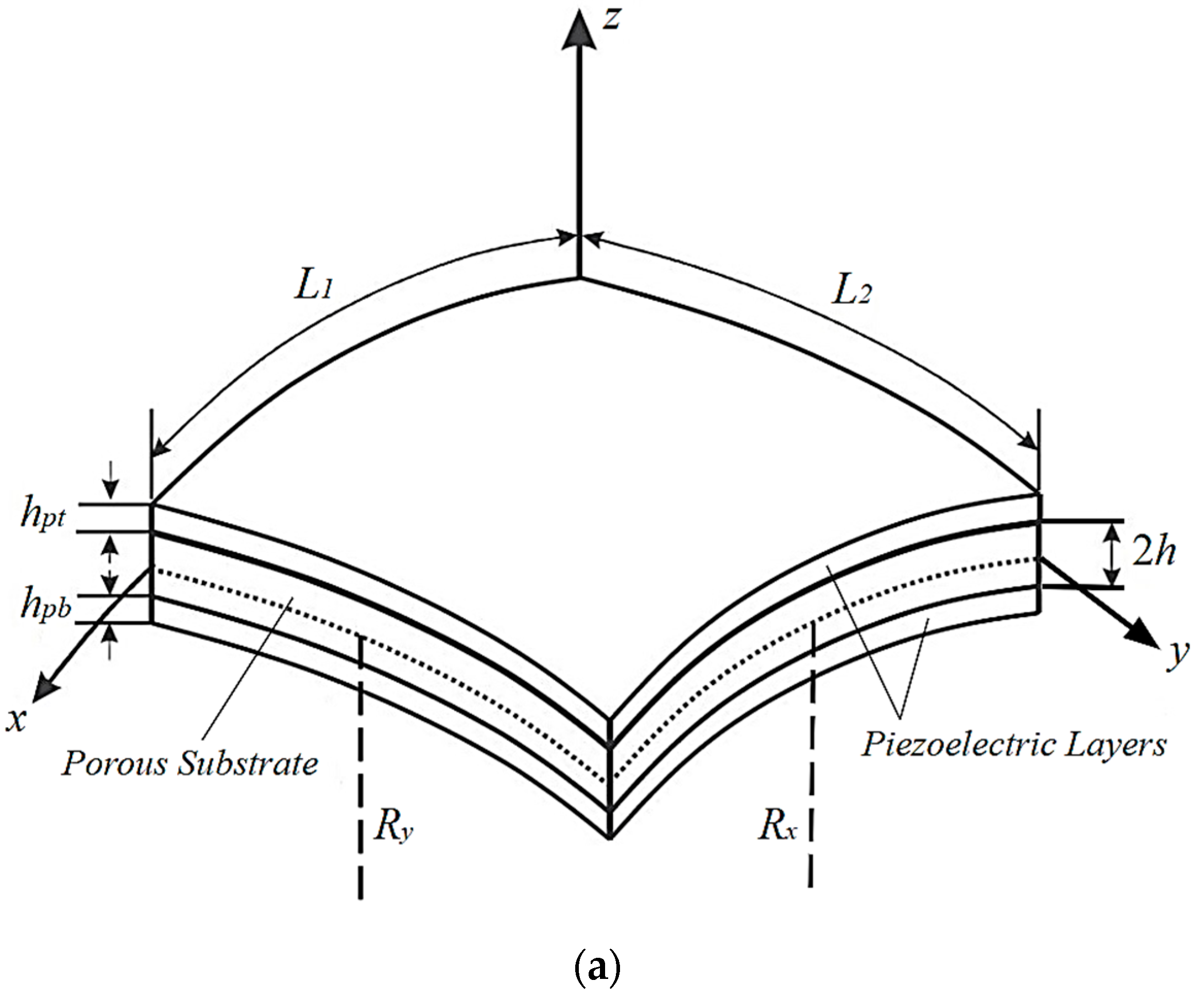
Figure 1. Sketch of porous bimorph (a) and unimorph (b) doubly curved panels.
Actuators 09 00007 g001aActuators 09 00007 g001b
Figure 2. Piezoelectric layers under SC (a) and OC (b) electrical condition.
Actuators 09 00007 g002aActuators 09 00007 g002b
Figure 3. Variation of the fundamental eigenfrequency versus the thickness ratio for coupled smart panels under SC condition.
Actuators 09 00007 g003
Figure 4. Variation of the fundamental eigenfrequency with respect to porosity coefficient.
Actuators 09 00007 g004
Figure 5. Variations of the first two frequencies of spherical porous bimorph and unimorph shells with respect to Rx/L1 (L1/L2 = 1, Ry/L1 = 5, 2h/L1 = 0.05, Hp/2h = 0.5, e = 0.2).
Actuators 09 00007 g005
Figure 6. Variation of the fundamental frequency versus the length ratio (Hp/2h = 0.5, e = 0.2).
Actuators 09 00007 g006
Figure 7. The effect of piezoelectric layers’ thickness on the fundamental frequency of bimorphs and unimorphs.
Actuators 09 00007 g007
Figure 8. The effect of the thickness ratio on the first three resonance frequencies of porous bimorph and unimorph spherical shells (e = 0.3).
Actuators 09 00007 g008
Figure 9. The mechanical and electrical effects of piezoelectric layers on the first three natural frequencies of spherical bimorphs and unimorphs.
Actuators 09 00007 g009
Figure 10. The effect of porosity parameter on the first three resonance frequencies of porous bimorph spherical shells (L1/L2 = 1, Rx/L1 = Ry/L1 = 5, 2h/L1 = 0.1, Hp/2h = 0.2).
Actuators 09 00007 g010
Table 1. Comparison of the fundamental eigenfrequency (Hz) of a bimorph isotropic shell.
EBCL1/RxHp/2hRef. [60]Present
SC0.00.1839.368838.273
0.2801.794799.360
0.10.1853.147852.075
0.2813.413811.024
OC0.00.1856.455854.844
0.2833.781829.958
0.10.1870.057868.476
0.2845.108841.347
Table 2. Comparison of the first ten eigenfrequencies (Hz) of a bimorph isotropic plate in SC condition.
Mode (m,n)Ref. [69]Ref. [64]Ref. [61]Present
1st (1,1)144.25145.35145.35144.49
2nd (1,2)359.00363.05363.06360.89
3rd (2,1)359.00363.05363.06360.89
4th (2,2)564.10580.35580.37576.90
5th (1,3)717.80725.00725.03720.70
6th (3,1)717.80725.00725.03720.70
7th (2,3)908.25941.64941.69936.06
8th (3,2)908.25941.64941.69936.06
9th (1,4)1223.141229.881229.961222.61
10th (4,1)1223.141229.881229.961222.61
Table 3. Comparison of the fundamental eigenfrequencies (Hz) for piezoelectric bimorphs and unimorphs with isotropic substrate.
GeometryHp/2hBimorphUnimorph
Ref. [59]PresentRef. [59]Present
Spherical0.52652265326542654
1.02405240824112411
2.02211221522172217
Cylindrical0.51526152715311531
1.01383138713931393
2.01273128012851285
Plate0.5873875887887
1.0791797813813
2.0730743755755
Table 4. Fundamental eigenfrequencies (Hz) of smart porous panels having various geometries (L1/L2 = 1, Rx/L1 = 5, 2h/L1 = 0.05, Hp/2h = 0.2).
EBCeSpherical
(Ry/L1 = Rx/L1)
Cylindrical
(Ry/L1 = ∞)
Plate
(Ry/L1 = Rx/L1 = ∞)
Hyperbolic Paraboloidal
(Ry/L1 = -Rx/L1)
Bimorph
SC0.0280.488253.228244.123242.135
0.1277.570251.004242.163240.189
0.2274.537248.677240.104238.147
0.3271.374246.232237.931235.992
0.4268.070243.653235.627233.706
0.5264.614240.924233.173231.271
OC0.0299.762273.571264.980262.815
0.1297.286271.846263.589261.434
0.2294.738270.074262.168260.023
0.3292.116268.254260.720258.586
0.4289.423266.391259.252257.129
0.5286.673264.500257.784255.672
Unimorph
SC0.0281.395254.198245.202243.203
0.1276.825250.150241.350239.382
0.2271.804245.632237.019235.086
0.3266.223240.522232.082230.189
0.4259.937234.655226.365224.520
0.5252.739227.794219.620217.829
OC0.0308.683278.646265.389263.218
0.1303.993274.389261.260259.123
0.2298.796269.602256.590254.491
0.3292.975264.155251.242249.186
0.4286.368257.868245.028243.023
0.5278.758250.492237.683235.739
Table 5. Fundamental SC eigenfrequencies (Hz) of porous bimorph panels (L1/L2 = 1, e = 0.2).
Geometry of the Smart PanelRx/L1 = 1Rx/L1 = 2Rx/L1 = 5Rx/L1 = 10
2h/L1 = 0.1, Hp/2h = 0.05
Spherical (Ry/L1 = Rx/L1)817.439572.816474.190458.105
Cylindrical (Ry/L1 = )549.656480.008457.156453.776
Plate (Ry/L1 = Rx/L1 = )452.686452.686452.686452.686
Hyperbolic Paraboloidal (Ry/L1 = -Rx/L1)369.247429.736448.902451.736
2h/L1 = 0.1, Hp/2h = 0.1
Spherical (Ry/L1 = Rx/L1)794.466564.937473.786459.051
Cylindrical (Ry/L1 = )541.781478.626458.098455.074
Plate (Ry/L1 = Rx/L1 = )454.102454.102454.102454.102
Hyperbolic Paraboloidal (Ry/L1 = -Rx/L1)370.360431.054450.301453.147
2h/L1 = 0.15, Hp/2h = 0.05
Spherical (Ry/L1 = Rx/L1)911.460727.852662.487652.559
Cylindrical (Ry/L1 = )694.283661.115651.139649.757
Plate (Ry/L1 = Rx/L1 = )649.386649.386649.386649.386
Hyperbolic Paraboloidal (Ry/L1 = -Rx/L1)526.775615.218643.723647.963
2h/L1 = 0.15, Hp/2h = 0.1
Spherical (Ry/L1 = Rx/L1)889.776720.098660.438651.429
Cylindrical (Ry/L1 = )686.543658.381650.006648.858
Plate (Ry/L1 = Rx/L1 = )648.562648.562648.562648.562
Hyperbolic Paraboloidal (Ry/L1 = -Rx/L1)525.963614.352642.888647.136
Table 6. Fundamental SC eigenfrequencies (Hz) of porous unimorph panels (L1/L2 = 1, e = 0.2).
Geometry of the Smart PanelRx/L1 = 1Rx/L1 = 2Rx/L1 = 5Rx/L1 = 10
2h/L1 = 0.1, Hp/2h = 0.05
Spherical (Ry/L1 = Rx/L1)819.827572.226472.471456.188
Cylindrical (Ry/L1 = )548.928478.424455.241451.794
Plate (Ry/L1 = Rx/L1 = )450.657450.657450.657450.657
Hyperbolic Paraboloidal (Ry/L1 = -Rx/L1)367.585427.808446.890449.711
2h/L1 = 0.1, Hp/2h = 0.1
Spherical (Ry/L1 = Rx/L1)798.410563.822470.813455.765
Cylindrical (Ry/L1 = )540.425475.869454.816451.688
Plate (Ry/L1 = Rx/L1 = )450.646450.646450.646450.646
Hyperbolic Paraboloidal (Ry/L1 = -Rx/L1)367.510427.764446.872449.698
2h/L1 = 0.15, Hp/2h = 0.05
Spherical (Ry/L1 = Rx/L1)914.868727.352660.50650.254
Cylindrical (Ry/L1 = )693.449659.300648.835647.317
Plate (Ry/L1 = Rx/L1 = )646.825646.825646.825646.825
Hyperbolic Paraboloidal (Ry/L1 = -Rx/L1)524.677612.786641.183645.407
2h/L1 = 0.15, Hp/2h = 0.1
Spherical (Ry/L1 = Rx/L1)895.375719.168657.105647.585
Cylindrical (Ry/L1 = )685.017655.306646.164644.804
Plate (Ry/L1 = Rx/L1 = )644.319644.319644.319644.319
Hyperbolic Paraboloidal (Ry/L1 = -Rx/L1)522.440610.305638.677642.901
Table 7. Fundamental eigenfrequencies (Hz) of smart porous panels (L1/L2 = 1, Rx/L1 = 5, 2h/L1 = 0.1, e = 0.3).
Hp/2hBimorphUnimorph
(eij = 0 1)SC (Ω(%) 2)OC (Ω(%) 2)(eij = 0 1)SC (Ω(%) 2)OC (Ω(%) 2)
Spherical (Ry/L1 = Rx/L1)
0.0468.898468.898 (0.00)468.898 (0.00)468.898468.898 (0.00)468.898 (0.00)
0.1467.185467.205 (0.00)490.957 (5.09)461.490461.490 (0.00)488.044 (5.75)
0.2473.266473.395 (0.03)512.563 (8.30)464.088464.088 (0.00)506.619 (9.16)
0.3483.409483.762 (0.07)533.559 (10.4)472.066472.066 (0.00)524.660 (11.1)
0.4495.832496.527 (0.14)553.864 (11.7)483.163483.163 (0.00)542.115 (12.2)
Cylindrical (Ry/L1 = )
0.0450.644450.644 (0.00)450.644 (0.00)450.644450.644 (0.00)450.644 (0.00)
0.1451.961451.982 (0.00)476.423 (5.41)445.870445.870 (0.00)470.093 (5.43)
0.2460.132460.265 (0.03)500.343 (8.74)450.444450.444 (0.00)489.287 (8.62)
0.3471.819472.182 (0.08)522.934 (10.8)459.984459.984 (0.00)508.060 (10.5)
0.4485.438486.150 (0.15)544.411 (12.1)472.363472.363 (0.00)526.285 (11.4)
Plate (Ry/L1 = Rx/L1 = )
0.0445.780445.780 (0.00)445.780 (0.00)445.780445.780 (0.00)445.780 (0.00)
0.1448.158448.180 (0.00)473.069 (5.56)441.867441.867 (0.00)463.333 (4.86)
0.2457.080457.215 (0.03)497.912 (8.93)447.164447.164 (0.00)481.775 (7.74)
0.3469.339469.707 (0.08)521.138 (11.0)457.328457.328 (0.00)500.345 (9.41)
0.4483.415484.136 (0.15)543.091 (12.3)470.262470.262 (0.00)518.664 (10.3)
Hyperbolic Paraboloidal (Ry/L1 = -Rx/L1)
0.0442.057442.057 (0.00)442.057 (0.00)442.057442.057 (0.00)442.057 (0.00)
0.1444.406444.427 (0.00)469.070 (5.55)438.167438.167 (0.00)459.427 (4.85)
0.2453.234453.368 (0.03)493.662 (8.92)443.398443.398 (0.00)477.665 (7.73)
0.3465.365465.730 (0.08)516.631 (11.0)453.449453.449 (0.00)496.020 (9.93)
0.4479.293480.006 (0.15)538.329 (12.3)466.240466.240 (0.00)514.118 (10.3)
1 Natural frequency without piezo effect, 2 Ω = ( ( ω ( sc / oc ) ω ( e i j = 0 ) ) / ω ( e i j = 0 ) ) *100