Article

Microfluidic Jetting Deformation and Pinching-off Mechanism in Capillary Tubes by Using Traveling Surface Acoustic Waves

School of Mechanical Engineering and Automation, Harbin Institute of Technology, Shenzhen 518055, China
*
Author to whom correspondence should be addressed.
Actuators 2020, 9(1), 5; https://doi.org/10.3390/act9010005
Submission received: 27 December 2019 / Revised: 14 January 2020 / Accepted: 20 January 2020 / Published: 23 January 2020

Abstract

:
To date, there has been little research attention paid to jetting deformation and pinching-off of microfluidic flows induced by the surface acoustic wave (SAW) mechanism. Further, such studies were almost limited to one sessile drop actuation without any confinement mechanisms. Such a scenario is likely attributable to the mechanism’s relatively poor controllability, the difficulty of maintaining the fluid loading position and issues related to stability and repeatability. In this paper, a novel SAW-microfluidic jetting system with a vertical capillary tube was designed, accompanied by a large number of experiments investigating the single droplet jetting mechanism with different device dimensions, resonance frequencies and radio frequency (RF) power capabilities. The study began with the whole jetting deformation and droplet pinching off through the use of a microscope with a high-speed camera, after which the results were discussed to explain the droplet jetting mechanism in a vertical capillary tube. After that, the study continued with experimental and theoretical examinations for high-quality single droplet jetting conditions. Jetting characterization parameters, including threshold RF power, resonance frequency, liquid volume, pinching off droplet dimensions, were thoroughly analyzed. Lastly, the Weber number range, a significant parameter in SAW-microfluidic jetting, was verified, and the pinching off microdroplet dimension was analyzed and compared via experiments. The significance of this study lies in the realization of microfluidic drop-on-demand based on SAW technology.

1. Introduction

Microfluidic droplets jetting technology attracts great attention in the fields of inkjet printing in industrial production [1], dispensing in the microelectronics and pharmaceutical industry [2], DNA and protein distribution in biomedicine [3], rapid prototyping of a complex material device in a microcircuit, aviation and architectural science [4]. In particular, realizing microfluidic drop-on-demand jetting allows for complete discrete controllability of the whole jetting process, which mainly includes controlling the jetting droplet diameter, velocity, frequency and direction. At present, the types of droplet jetting methods according to the driving modes mainly include pneumatic [5], thermal bubble [6], piezoelectric [7], electromagnetic [8], mechanical [9] and ultrasound focusing [10]. For some microscale device applications, there are some drawbacks in these methods, such as the limited driving force and inconvenient control of air pressure supply in the pneumatic jetting device, the necessary condition for special liquids that can be heated and evaporated quickly in the thermal bubble jetting device, nonlinearity, creep, aging and hysteresis problems in piezoelectric ceramics, limitation in conductive metal liquid driven by Lorentz force in a magnetic field, mechanical wear of moving parts in a mechanical cavity and the highly complicated and costly components in the ultrasonic system.
In recent years, some potential applications in manipulating microscale liquid, typically including four regimes for drop oscillation [11,12], transportation [13], ejection [14] and atomization [15,16], have been reported with the use of surface acoustic wave (SAW) devices, which are made from different piezoelectric materials such as a bulk substrate (i.e., quartz, LiNbO3, and LiTaO3) and thin-film substrates (i.e., ZnO and AlN) [17]. Specifically, fluids undergoing jetting should have sufficient inertia to overcome the viscous stress and surface tension acting on the interface of the fluid and surrounding media [14]. Compared to other droplet-generation mechanisms in microfluidics such as pneumatic, bubbling, piezoelectric, electromagnetic, mechanical and ultrasonic vibration [5,6,7,8,9,10], the SAW-microfluidic jetting technology has the advantages of great force, high efficiency, flexible design, simple fabrication, cost-effectiveness, lightweight and miniaturization for easy integration, and relatively wide fluid viscosity range. The droplet jetting phenomenon actuated by SAW was first reported in the last decade of the twentieth century [18], in which radio frequency (RF) power for jetting has been concluded as between the effects of more RF power in simply moving the drop and the effects of less RF power in atomizing the drop. The authors in [18] also worked out a theoretical SAW streaming force in the droplet from the acoustic streaming phenomenon. Twenty years later, a pair of elliptical focusing single-phase unidirectional transducers (SPUDTs) was exploited, in which the focus of the acoustic energy was a small region beneath a drop placed on the surface of a piezoelectric material [14]. The SPUDTs device caused a vertically elongated jet from drops with dimensions greater than the fluid sound wavelength, and subsequently, the elongated jet suffered from the usual Rayleigh–Plateau instability to pinch-off droplets. Later, a non-piezoelectric phononic crystal, called superstrate, was introduced, which was placed in contact with the piezoelectric substrate [19]. The superstrate excited the Lamb waves to interact with the phononic crystal lattice, resulting in the focusing of the energy for shaping fluid drops at a particular location in a frequency-dependent manner. Different jetting deformation phenomena as the substrate surface wettability changed were found, showing that a sharp jetting pinching point was instantaneously formed at the apex of the droplet with smaller jet radius and that the inertial body force was mostly concentrated at the apex of the droplet on the superhydrophobic substrate [20]. A parent sessile drop can be formed on the SAW chip through a 150-μm inner diameter pulled capillary tube connected to a 3D printed liquid reservoir [21]. In general, droplet jetting phenomena were achieved by placing a sessile drop on the propagation path of the SAW on the surface of the chip, and jetting performances were improved by coating with a hydrophobic film. Although this kind of droplet jetting method driven by SAW does not require any nozzle or orifice to confine the liquid, the poor practicability was subjected to the stable continuous liquid supply. Moreover, it is difficult to achieve simulation analysis for understanding the interaction mechanism and the relationship between the parameters because of the complicated fluid-structure interaction and nonlinear relationship involved in the technology.
For further exploration of the droplet-generation mechanism based on SAW technology and for the realization of continuous and high-efficiency droplet jetting devices, this study focuses its investigation into the liquid jetting deformation behavior with a vertical cylindrical capillary tube placed in the middle of one pair of aligned straight interdigital transducers (IDTs). Capillary tube with different parameters was used, and different initial liquid conditions were set to explore a single droplet jetting conditions by using traveling SAW technology. The relationships between the single droplet jetting parameters, including the pinching-off droplet diameter, jetting speed, Weber number, and the response frequencies of the SAW device and the input RF power threshold, are discussed in detail for further optimizing the jetting phenomenon. Droplet jetting research in a vertical capillary tube offers the possibility to achieve a repetitive single-droplet generation with the tunable and drop-on-demand requirements.

2. Materials and Methods

2.1. SAW Device Fabrication

As the driving source of liquid jetting, small-aperture-straight-electrode (SASE) SAW devices have a higher energy density output performance and a corresponding higher driving capability than large aperture SAW devices. Besides, although focused SAW devices were used in some literature [14] to concentrate energy on a focal point, the wave radiation path is a fan-shaped area. The SASE SAW device could ensure energy concentration and a more standardized wave path, which is more conducive to design and integrate with a vertical capillary tube. The SASE SAW devices with frequencies of 29.4, 58.9 and 88.5 MHz depicted in Figure 1a were produced by fabricating 150-nm-thick straight finger Au electrode pairs on a 0.5-mm-thick 128°-rotated Y-cut X-propagating single-crystal LiNbO3 wafer using a standard lift-off technique and photolithography technique. The wavelength of the devices was determined by the metal electrode width and the gap between them. Empirically, the width and gap of the standard straight IDT fingers were set to be identically equal to a quarter of the wavelength, λ/4, thereby maximizing the electromechanical coupling coefficient [22]. The resonant frequency referred to as f = c/λ depends on the designed wavelength and the wave propagation speed, which are mainly determined by the material, the substrate cut type, and the propagation direction [23]. On the basis of the frequency design, the structural parameters of IDT are shown in Figure 1b; the electrode width ‘a’ and gap ‘b’ were set to 11, 22 and 33 μm, respectively; the width of the bus bar was B = 1.5 mm; the distance between the electrode tip and the bus bar was v = 5 μm; the distance between the bus bar terminal and the first electrode was A = 2 mm; the aperture was W = 0.5 mm; the port distance between two symmetrical IDTs was Lp = 6.6 mm; and the electrode pairs number was 30. Figure 1c provides the SAW devices’ frequency resonant characteristic curve measured using a network analyzer (E5073C, Agilent, Palo Alto, CA, USA).

2.2. Experimental Setup

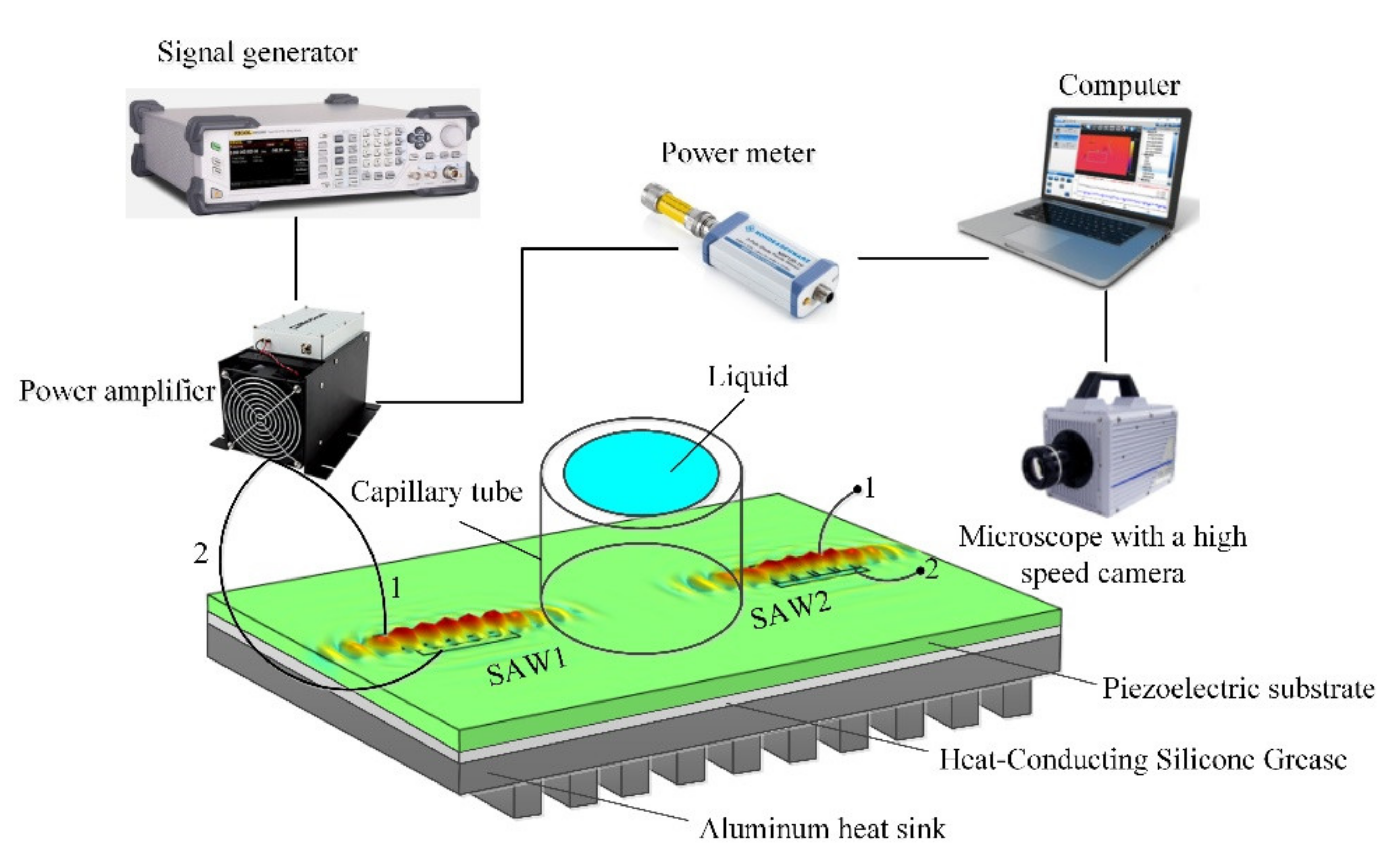
Figure 2 shows a block schematic diagram of the experimental system. Each SAW device was connected to a standard signal generator (DSG3000, RIGOL, Beijing, China) and an RF power amplifier (LZY-22, Mini-circuit, New York, NYC, USA) via SMA cables. The amplified RF signal was measured by an RF power meter (NRP18S-25, ROHDE&SCHWARZ, Munich, Germany) before being fed into the IDTs. The whole ejecting phenomenon was observed through a microscope (D00545, Photron, Tokyo, Japan) with a high-speed camera (Photron FASTCAM SA8, Tokyo, Japan) having a frame rate of up to 40,000 frames/s, with the video and pictures of the results recorded using a computer with image processing software. A 100-W LED light was the illumination source in the experiment. A transparent plastic capillary tube was bonded at the center of the SAW device surface by using glass adhesive and then baked the device in an incubator at 100 ℃ for ten minutes to realize the solidification of the adhesive. As shown in the figure, glass adhesive would be unnecessary in the area of the SAW propagation entrance so that the traveling SAW can directly and efficiently interact with the liquid instead of being absorbed by other substances to reduce the ability for driving the liquid. For each group of experiments, the time of the continuous RF signal was set to be one second. Each experimental test would be repeated at least three times to ensure the repeatability and accuracy under the same input conditions and liquid samples.

3. Results and Discussion

3.1. Droplet Jetting Mechanism in Vertical Capillary Tube

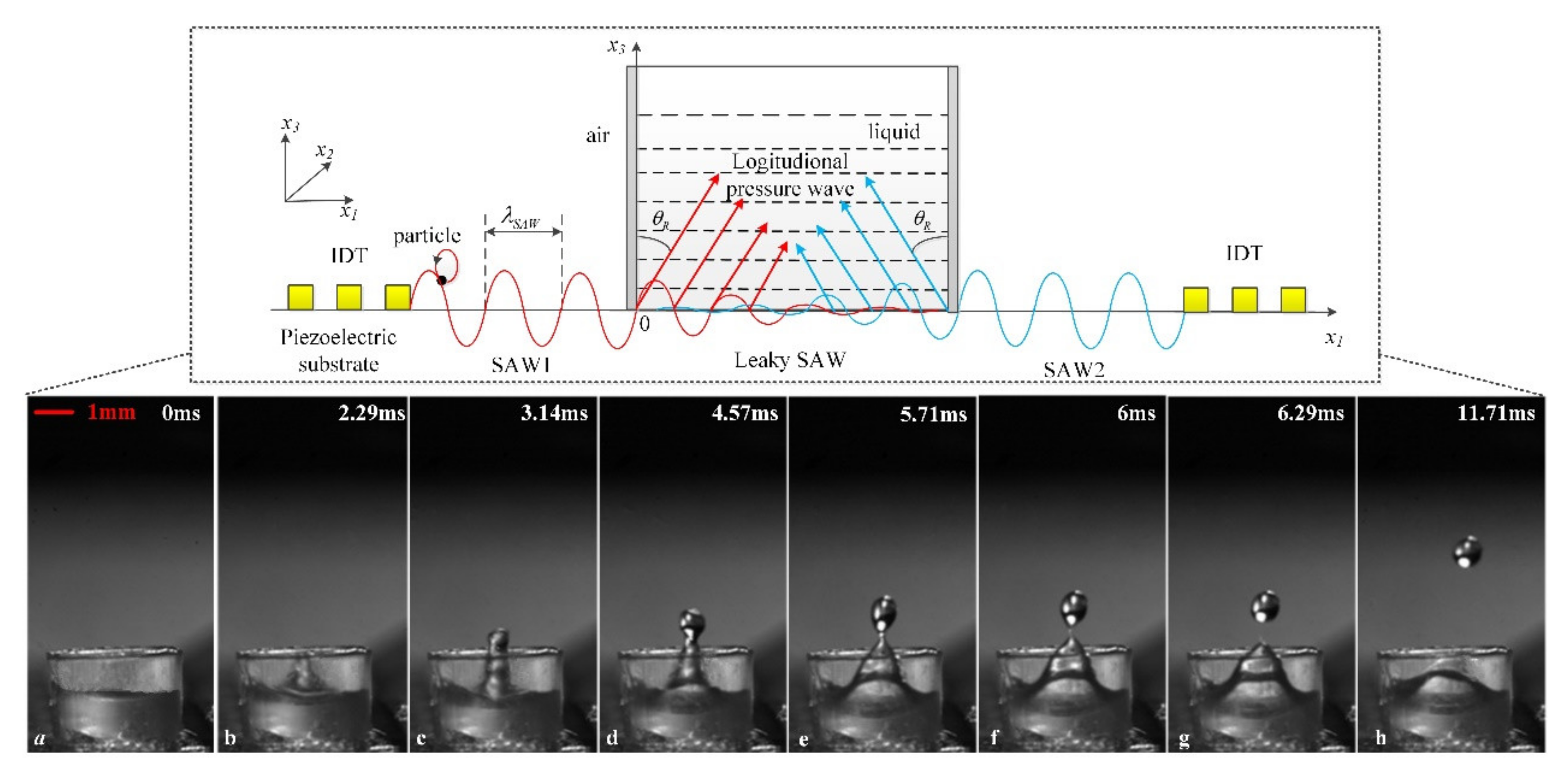
When a vertical capillary tube is mounted on the substrate surface to store a liquid, the original form of the fluid is constrained and different from the single sessile drop. To illustrate the whole droplet generation mechanism in a vertical capillary tube, 10-μL deionized water loaded in a transparent plastic tube with 3-mm inner diameter, 2-mm height, 0.1-mm wall thickness by a Micro-Volume Kit micropipette was actuated simultaneously with a pair of 29.4-MHz straight SAW devices. All of the particles on the piezoelectric substrate surface have an elliptical displacement, which can be decomposed into two components, namely, a transverse component along the SAW propagation direction and a longitudinal one perpendicular to the surface. When the generated traveling SAW comes into contact with the liquid in the vertical capillary tube, the acoustic energy continuously diffracts into the liquid because of the mismatch sound velocity in the fluid and the piezoelectric substrate to form an inclination angle, referred to as the Rayleigh angle θR = sin−1(cf/cs) [16]. The primary traveling SAW will transform into a leaky SAW that continues propagating on the interface of the fluid and substrate, and a longitudinal pressure wave that propagates along the Rayleigh angle direction to induce a SAW streaming force in jetting the fluid. When the input RF power was set in the range of 0.3–1.7 W, a more severe vibration phenomenon of the deionized water was observed as the applied RF power increased. With further increase of the input RF power, within 1.8–2.5 W, the liquid would deform and elongate discernibly perpendicular to the substrate surface for the superposition of two opposite-diffracted SAWs, but no pinch-off phenomenon would take place during the whole process. Consequently, the higher the input RF power applied, the longer is the liquid column formed. Moreover, the liquid column would repeatedly fall back from the highest point if the input RF power would be unchanged steadily. However, when the RF power is increased to a threshold value (2.6 W), the liquid will experience distortion, elongation, single-droplet pinching-off, and continuous vibration of the residual liquid, as illustrated in Figure 3. As the RF power continues to increase, multiple smaller droplets are generated with the main droplet pinching-off. Single-droplet generation, as the most essential and meaningful stage, is discussed and explained in detail as follows.
Before the 2.6 W RF power was applied to excite the SAW, the fluid remained in a static state in the tube along the propagation pathway of the SAW, as shown in Figure 3a. When the SAW was excited, two columns opposite SAW almost simultaneously met the liquid at the left and right bottom of the capillary tube. Owing to the diffraction of the SAW streaming force, the liquid began to distort, as illustrated in Figure 3b–d. Note, however, that such distortion along the direction vertical to the substrate surface came from the resultant body force from the two opposite SAWs in the vertical direction. Accompanied by the liquid column reaching the highest point, a narrowing neck gradually formed to cause one droplet eventually to pinch-off from the tip of the whole liquid, as shown in Figure 3e,f. The droplet then continued moving upward with the inertia effect, as shown in Figure 3g,h, to the highest point, and fell because of gravity. It took approximately 6.3 ms from the deformation of the liquid level to the droplet pinching-off. Although the input RF power was constant, only one droplet pinching-off can be observed, and the remaining liquid would keep on vibrating until the input RF power has been shut down. If the applied RF power is great enough, then the liquid column would elongate much higher and then simultaneously generate multiple small droplets.

3.2. Single Droplet Jetting Condition

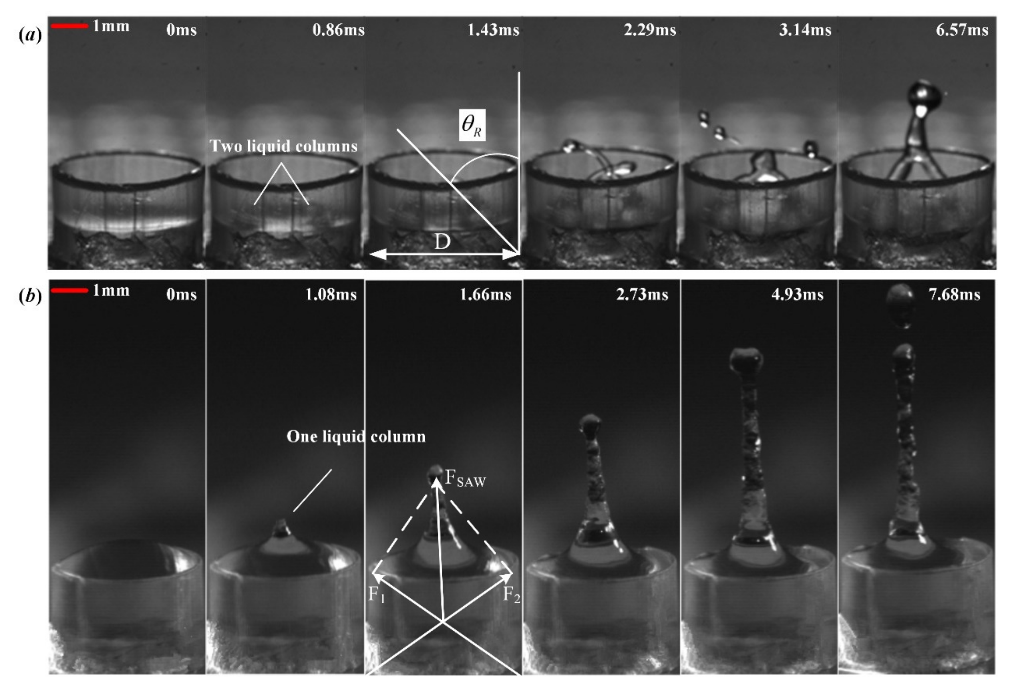
The initial conditions of the liquid in the vertical capillary tube have a significant influence on the droplet jetting quality. In the absence of RF power input, the surface tension maintaining the system stability that the liquid remains stationary in the vertical capillary tube. Firstly, if the initial liquid level is uneven in the vertical capillary tube, the quality of the droplet jetting will be severely affected, and even the direction of the injection will get offset from the centreline, which is shown in Figure 4. This is because of the more significant inertia effect of the liquid column generated at the higher liquid level. Two asymmetric liquid columns were generated and superposed in the middle that causes the jetting direction incline towards the lower liquid level. When a vertical capillary tube with an inner diameter of 6 mm was used, and the liquid level in the vertical capillary tube was maintained the same as in Figure 3, some changes were taken place in the jetting manner shown in Figure 5. First of all, two liquid columns above the water level were simultaneously generated at an angle of about 45° in the vertical capillary tube. Then the two liquid columns are gradually pushed and elongated towards the centreline of the vertical capillary tube until they meet in the middle. The two liquid columns would superimpose to change the jetting direction perpendicular to the SAW device surface after meeting in the middle for the force cancellation in the horizontal direction and the force superposition in the vertical direction. Therefore, the diameter of the vertical capillary tube should not be too wide so that the two liquid columns may pinch off early before being superimposed.
When a vertical capillary tube with an inner diameter of 3 mm was used and 5-μL deionized water loaded in the capillary tube, the liquid level in the vertical capillary tube is about 0.8 mm. At this point, the liquid level in the vertical capillary tube is relatively too low. Two inclined liquid columns would generate almost simultaneously from the two opposite sides above the water level and even pinch-off before the two liquid columns meet, which would cause poor jetting quality shown in Figure 6a. When a vertical capillary tube with an inner diameter of 3 mm was used and 15-μL deionized water loaded in the vertical capillary tube, the vertical capillary tube was filled with the liquid, and a convex was formed on the top surface. At this point, the liquid level in the vertical capillary tube is relatively too high by about 2 mm, and only one regular vertical liquid column can be observed as Figure 6b. The liquid column was stretched up to a length of about 4 mm and breaks to form droplets. However, if the liquid level is high enough, then the static equilibrium relationship would be broken up so that the additional pressure would squeeze the liquid to burst out across the bottom gap. Eventually, the jetting performance would become irregular, in such a way as the phenomenon of atomization would take place when a thin meniscus forms or is ejected along the outer wall of the capillary tube. There is a critical capillary pressure burst value to control the liquid to stay in the tube. Only the capillary pressure on the bottom gap is overcome by liquid gravity and additional pressure, the liquid can flow out to break this equilibrium state, as determined by the properties of the liquid, the liquid level, the hydrophobic or hydrophilic of the wall materials, and scale of the gap at the bottom [24]. Figure 6 suggests that liquid level should be selected reasonably according to capillary tube size, which determines the characteristic interaction length between the SAW and liquid. Assuming that the jetting inclination angle is θR and the inner diameter of the capillary is D, the optimal liquid level may be higher than h = D/2tanθR and lower than the capillary pressure burst threshold. Otherwise, the condition of jetting deformation and breaking up may be uncontrollable and meaningless. Therefore, single-droplet jetting with good quality must satisfy four conditions: the initial liquid level must be uniform; the diameter of the vertical capillary tube is suitable as two to four times the SAW attenuation length; the height of the liquid level lies between D/2tanθR and the capillary pressure burst threshold; the input RF power happens to be the jetting threshold power value.

3.3. Analysis of Jetting Characterization

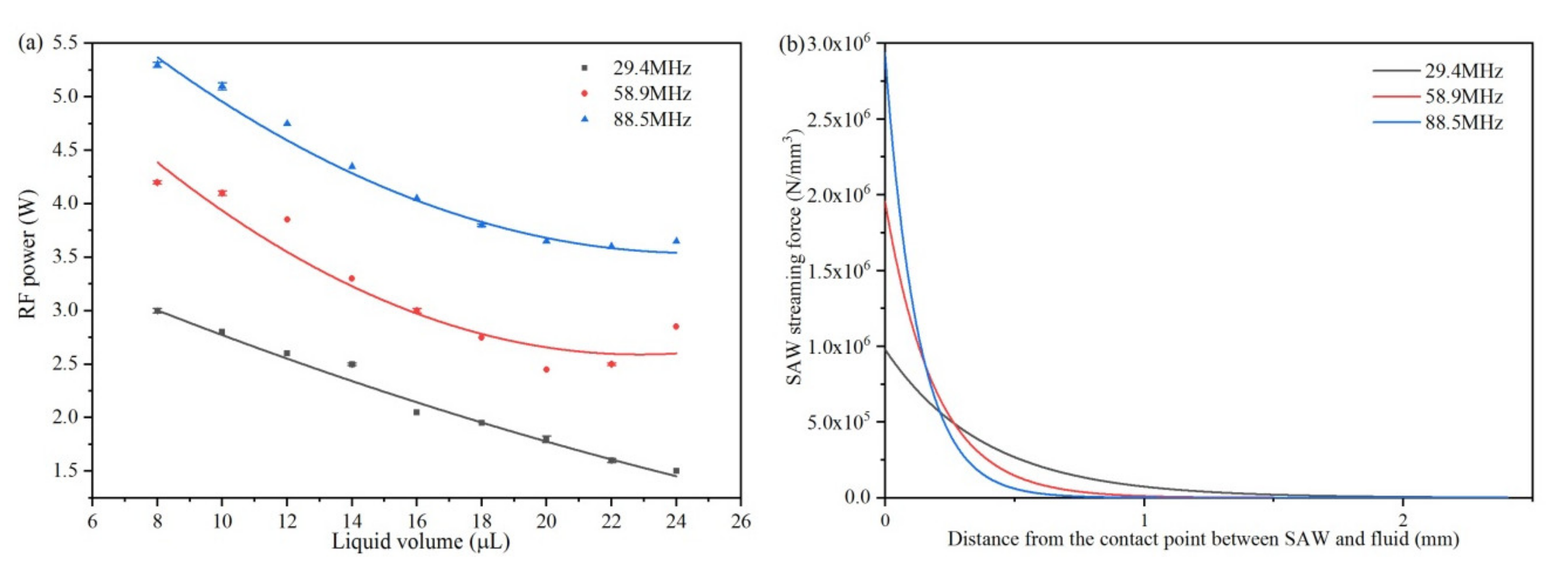
When the initial state of the fluid is determined, another main constraint in achieving SAW-microfluidic jetting lies in the SAW frequency. As Figure 7a shows, the critical input RF powers required to achieve single droplet jetting and pinching-off phenomena dramatically vary with frequencies. By increasing the SAW device operating frequency, the critical input RF power value increases significantly, indicating that the SAW-microfluidic jetting action becomes more efficient at a lower frequency for the same volume of liquid added in the capillary tube. To illustrate the mechanism of the frequency effect, the energy emission from the SAW on the LiNbO3 substrate surface to the longitudinal wave in the liquid should be considered. Once in contact with the fluid, the SAW energy then attenuates exponentially along its propagation direction on the substrate surface:
v ˙ = v ˙ m e α x
where v ˙ is the vibration velocity of the SAW along its propagation direction and v ˙ m is the maximum vibration velocity of the SAW, occurring before contact with the liquid. Accordingly:
α = L S A W 1 = ρ f v f / ρ s v R λ = ρ f v f f / ρ s v R 2
where α is the attenuation coefficient, LSAW is the attenuation length of SAW, with ρf and ρs being a water density of 998 kg/m3 and substrate density of 4630 kg/m3, respectively, vf and vR being the velocity of longitudinal pressure wave in the water of 1498 m/s and Rayleigh wave phase velocity of 3974 m/s. According to the relationship, α−1~f−1, the attenuation length of SAW decreases inversely with the device frequency, which means that decreasing the excitation frequency would result in a longer interaction between SAW and the fluid. Furthermore, the emitted SAW energy into the fluid will result in a net body force [18]:
F s = ρ 0 ( 1 + α 1 2 ) 3 / 2 A 2 ω 2 k i exp 2 ( k i x 1 + α 1 k i x 3 )
where ki is the imaginary part of leaky SAW wave number, α1 is the damping factor as α1 = jα, ω is the angular frequency and A is the SAW amplitude that can be described by [25]:
A / λ = 8.15 × 10 6 P D 0.225 + 5 × 10 6 P D 0.8
with P D in Watts being the RF power applied to the SAW device. Considering a single droplet jetting for 10 μL deionized water loaded in a transparent plastic capillary tube with dimensions of 3.0 mm × 0.1 mm × 3.0 mm, the applied RF powers of 2.6, 4.1 and 5.2 W are necessary for SAW response frequencies of 29.4, 58.9, and 88.5 MHz, respectively. Accordingly, the calculated SAW streaming force distribution in Figure 7b indicates that the SAW streaming force decreases exponentially along the longitudinal wave propagation direction in the fluid and that the interaction area decreases significantly with a higher SAW excitation frequency. Moreover, the characteristic height of the fluid in the capillary tube is much higher than the interaction distance at higher exciting frequencies. Therefore, a higher applied power threshold value for the SAW-microfluidic jetting and pinching-off phenomenon is needed for a higher resonant frequency, which is consistent with the results from the experiments. On the other hand, Figure 7a also indicates that only one value of the initial characteristic parameter of fluid corresponding to a specified jetting threshold RF power can cause one single ejected microdroplet to take place. In the case where the static equilibrium relationship of liquid in the capillary tube was not broken, the jetting threshold RF power gradually decreases as the liquid volume increases. Therefore, the result explains the more significant inertia effect of the liquid column generated at the higher liquid level under the same input RF power. The conclusion also explains why only once a droplet pinching off can be seen even though the value of the input RF power was the same and the remaining liquid in the capillary tube would still keep on vibrating. As part of the volume of the liquid has been pinched off and separated from the original liquid, a much higher RF power is needed to pinch-off the remaining liquid in the vertical capillary tube. On the other hand, the linearity relationship between the input RF power and the liquid volume in the range of 8 μL to 24 μL is excellent under the frequency of 29.4 MHz. Under the frequencies of 58.9 and 88.5 MHz, the linearity is also good when the liquid volume is less than 20 μL. Therefore, the liquid level can be set as low as possible in the case of meeting the requirements discussed in Section 3.2. As described previously, it changes the required threshold value of applied RF power for the same volume of liquid by affecting the energy density distribution at different frequencies. However, the ejected droplet dimension is almost not obviously affected by the SAW resonance frequency. The radius of the ejected droplet obtained was approximately equal to 0.52 mm for a 10-time repetition of the experiments at these frequencies. Only the jetting velocities were different (about 0.13, 0.15 and 0.17 m/s at 29.4, 58.9 and 88.5 MHz, respectively) for different RF power actuation values.
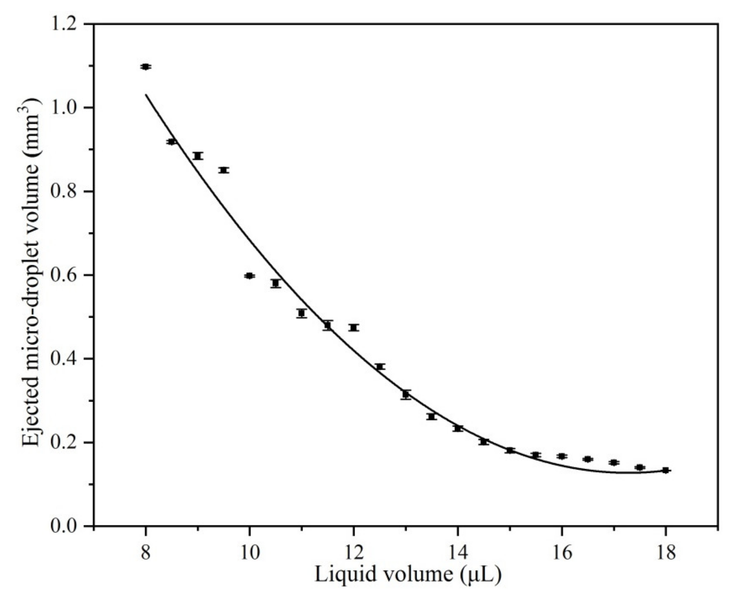
In Figure 8, the relationship between the dimension of the ejected microdroplet and liquid level in the capillary tube can be obtained by keeping the excitation frequency at 29.4 MHz and the capillary tube size at 3.0 mm × 0.1 mm × 3.0 mm unchanged. The ejected microdroplet volume gradually decreases with increases in liquid level in the vertical capillary tube. As a result, the size of the generated droplet is determined by the initial liquid characteristics in the vertical capillary tube. At the onset of jetting, the inertial energy induced by the SAW overcomes the surface tension on the interface and viscous force of the liquid in the vertical capillary tube. Assuming an elongated cylindrical column length of the jet Lj, a corresponding jet radius Rj, an initial jet velocity Uj, a pinching-off microdroplet radius rj with velocity vj, and a surface tension coefficient of the fluid γ, the jet Weber number could be defined as:
Wej = ρUj2Rj
and recasting six typical groups of the experimental data as Table 1, the onset of single-droplet jetting all occurred at Weber numbers between 0.1 and 0.4, which is consistent with the isolated sessile drop observed by Tan [14].

4. Conclusions

In this paper, we have designed a novel experimental method by mounting a vertical capillary tube on the 0.5-mm SAW propagation pathway center between two symmetrical small-aperture straight IDTs. Fluid jetting deformation and pinching off mechanism induced by traveling SAW for fluid loaded in a vertical capillary tube were investigated under three different resonance frequencies (29.4, 58.9, and 88.5 MHz). Compared with a sessile drop jetting, it shows apparent advantages in the strong ability for storing liquid, and more standardized and controllable for jetting manner.
A single micro-droplet jetting phenomenon was highlighted in this paper. When the input RF power was up to an appropriate threshold RF power value, two liquid columns were simultaneously generated at a specific angle on the left and right side and meet in the middle to superimpose into a vertical liquid column. The higher the input RF power applied, the more extended liquid column is formed. Accompanied by the liquid column reaching the highest point, a narrowing neck gradually formed to cause one droplet eventually to pinch-off from the tip of the whole liquid column. In general, the fluid would undergo a liquid column elongation, a single droplet pinching off, and continuously vibrating of the residual liquid until the RF power was shut down. In order to obtain better single droplet jetting quality, the level of the liquid in the vertical capillary tube must first be maintained even. Secondly, the inner diameter of the vertical capillary tube should be moderate that not too wide, and it could be 2–4 times the attenuation length. Moreover, assuming that the jetting inclination angle is θR and the inner diameter of the capillary is D, the optimal liquid level in vertical capillary tube may be higher than h = D/2tanθR and lower than the capillary pressure burst threshold. If the above conditions are not satisfied, the jetting direction of the liquid column and the droplet pinching off are not well controllable, which will affect the jetting quality.
The SAW streaming force decreases exponentially along the longitudinal wave propagation direction in the fluid, whereas the interaction area decreases significantly with higher SAW excitation frequency, so the corresponding threshold RF power required to achieve microfluidic jetting and pinching off phenomena is dramatically higher. Only one value of the initial characteristic parameter of fluid corresponding to a specified jetting threshold RF power can cause one single ejected microdroplet to take place. In the case where the static equilibrium relationship of liquid in the capillary was not broken, the jetting threshold RF power gradually decreases as the liquid volume increases. Besides, the dimensions of the ejected microdroplet decreased inversely with an increasing level of liquid in the vertical capillary tube. Nonetheless, the ejected droplet dimension is almost not affected by the SAW resonance frequency but determined by the initial characteristics of the liquid in the vertical capillary tube. Through calculation and analysis of parameters in microfluidic jetting, each onset of single-droplet jetting occurs at Weber numbers between 0.1 and 0.4. The successful investigation of this study will contribute to the SAW technology in realizing drop-on-demand jetting for practical applications such as inkjet printing, dispensing in electronic packaging, and material molding for biomedical engineering, aerospace and construction.

Author Contributions

Funding acquisition, H.H.; Investigation, Y.L.; Methodology, Y.L.; Software, J.C. and P.Z.; Supervision, H.H.; Writing—original draft, Y.L. All authors have read and agreed to the published version of the manuscript.

Funding

This work was supported by Science and Technology Plan Project of Shenzhen [grant numbers JSGG20170412143346791 and JCY20170413105740689].

Conflicts of Interest

There is no conflicts of interest regarding the publication of this paper.

References

  1. Hoath, S.D.; Harlen, O.G.; Hutchings, I.M. Jetting behavior of polymer solutions in drop-on-demand inkjet printing. J. Rheol. 2012, 56, 1109–1127. [Google Scholar] [CrossRef] [Green Version]
  2. Liu, Y.; Deng, G. The influence of fluid viscosity of fluid jetting dispensing. In Proceedings of the 2007 International Symposium on High Density packaging and Microsystem Integration, Shanghai, China, 26–28 June 2007; pp. 1–4. [Google Scholar]
  3. Barron, J.A.; Young, H.D.; Dlott, D.D.; Darfler, M.M.; Krizman, D.B.; Ringeisen, B.R. Printing of protein microarrays via a capillary-free fluid jetting mechanism. Proteomics 2005, 5, 4138–4144. [Google Scholar] [CrossRef]
  4. Zohar, R.; Sagi, D.; Sadowski, B. Jet print apparatus and method for printed circuit board manufacturing. U.S. Patent 6,754,551, 22 June 2004. [Google Scholar]
  5. Xie, D.; Zhang, H.; Shu, X.; Xiao, J.; Cao, S. Multi-materials drop-on-demand inkjet technology based on pneumatic diaphragm actuator. Sci. China Technol. Sci. 2010, 53, 1605–1611. [Google Scholar] [CrossRef]
  6. Karri, B.; Avila, S.R.G.; Loke, Y.C.; O’Shea, S.J.; Klaseboer, E.; Khoo, B.C.; Ohl, C.D. High-speed jetting and spray formation from bubble collapse. Phys. Rev. E 2012, 85, 015303. [Google Scholar] [CrossRef] [PubMed]
  7. Lee, D.G.; Lee, E.; Song, K.; Hur, S. Dynamics of the piezoelectric driven ink jetting. In Proceedings of the 71st Annual Meeting of the APS Division of Fluid Dynamics, Atlanta, GA, USA, 18–20 November 2018. [Google Scholar]
  8. Luo, Z.; Wang, X.; Wang, L.; Sun, D.; Li, Z. Drop-on-demand electromagnetic printing of metallic droplets. Mater. Lett. 2017, 188, 184–187. [Google Scholar] [CrossRef]
  9. Silverbrook, K. Micro electro-mechanical system for jetting of fluids. U.S. Patent 6,299,300, 10 September 2001. [Google Scholar]
  10. Tanaka, H.; Mizuno, Y.; Nakamura, K. Jetting of small droplet from microplate using focused ultrasound. Jpn. J. Appl. Phys. 2017, 56, 087202. [Google Scholar] [CrossRef]
  11. Shilton, R.J.; Travagliati, M.; Beltram, F.; Cecchini, M. Nanoliter-droplet acoustic streaming via ultra high frequency surface acoustic waves. Adv. Mater. 2014, 26, 4941–4946. [Google Scholar] [CrossRef] [Green Version]
  12. Ding, X.; Lin, S.C.S.; Kiraly, B.; Yue, H.; Li, S.; Chiang, K.I.; Huang, T.J. On-chip manipulation of single microparticles, cells, and organisms using surface acoustic waves. Proc. Natl. Acad. Sci. USA 2012, 109, 11105–11109. [Google Scholar] [CrossRef] [Green Version]
  13. Schmid, L.; Wixforth, A.; Weitz, D.A.; Franke, T. Novel surface acoustic wave (SAW)-driven closed PDMS flow chamber. Microfluid. Nanofluid. 2012, 12, 229–235. [Google Scholar] [CrossRef]
  14. Tan, M.K.; Friend, J.R.; Yeo, L.Y. Interfacial jetting phenomena induced by focused surface vibrations. Phys. Rev. Lett. 2009, 103, 024501. [Google Scholar] [CrossRef] [Green Version]
  15. Ju, J.; Yamagata, Y.; Ohmori, H.; Higuchi, T. High-frequency surface acoustic wave atomizer. Sens. Actuators A-Phys. 2008, 145, 437–441. [Google Scholar] [CrossRef]
  16. Qi, A.; Yeo, L.Y.; Friend, J.R. Interfacial destabilization and atomization driven by surface acoustic waves. Phys. Fluids 2008, 20, 074103. [Google Scholar] [CrossRef] [Green Version]
  17. Yeo, L.Y.; Friend, J.R. Surface acoustic wave microfluidics. Annu. Rev. Fluid Mech. 2014, 46, 379–406. [Google Scholar] [CrossRef] [Green Version]
  18. Shiokawa, S.; Matsui, Y.; Ueda, T. Study on SAW streaming and its application to fluid devices. Jpn. J. Appl. Phys. 1990, 29, 137. [Google Scholar] [CrossRef] [Green Version]
  19. Bourquin, Y.; Wilson, R.; Zhang, Y.; Reboud, J.; Cooper, J.M. Phononic crystals for shaping fluids. Adv. Mater. 2011, 23, 1458–1462. [Google Scholar] [CrossRef] [PubMed]
  20. Darmawan, M.; Byun, D. Focused surface acoustic wave induced jet formation on superhydrophobic surfaces. Microfluid. Nanofluid. 2015, 18, 1107–1114. [Google Scholar] [CrossRef]
  21. Castro, J.O.; Ramesan, S.; Rezk, A.R.; Yeo, L.Y. Continuous tuneable droplet jetting via pulsed surface acoustic wave jetting. Soft Matter 2018, 14, 5721–5727. [Google Scholar] [CrossRef]
  22. Nakanishi, H.; Nakamura, H.; Goto, R. High-electromechanical-coupling-coefficient surface acoustic wave resonator on Ta2O5/Al/LiNbO3 structure. Jpn. J. Appl. Phys. 2010, 49, 07HD21. [Google Scholar] [CrossRef]
  23. Nakahata, H.; Higaki, K.; Hachigo, A.; Shikata, S.; Fujimori, N.; Takahashi, Y.; Kajihara, T.; Yamamoto, Y. High frequency surface acoustic wave filter using ZnO/diamond/Si structure. Jpn. J. Appl. Phys. 1994, 33, 324. [Google Scholar] [CrossRef]
  24. Hassanizadeh, S.M.; Celia, M.A.; Dahle, H.K. Dynamic effect in the capillary pressure–saturation relationship and its impacts on unsaturated flow. Vadose Zone J. 2002, 1, 38–57. [Google Scholar] [CrossRef]
  25. Alghane, M.; Fu, Y.Q.; Chen, B.X.; Li, Y.; Desmulliez, M.P.Y.; Walton, A.J. Frequency effect on streaming phenomenon induced by Rayleigh surface acoustic wave in microdroplets. J. Appl. Phys. 2012, 112, 084902. [Google Scholar] [CrossRef] [Green Version]
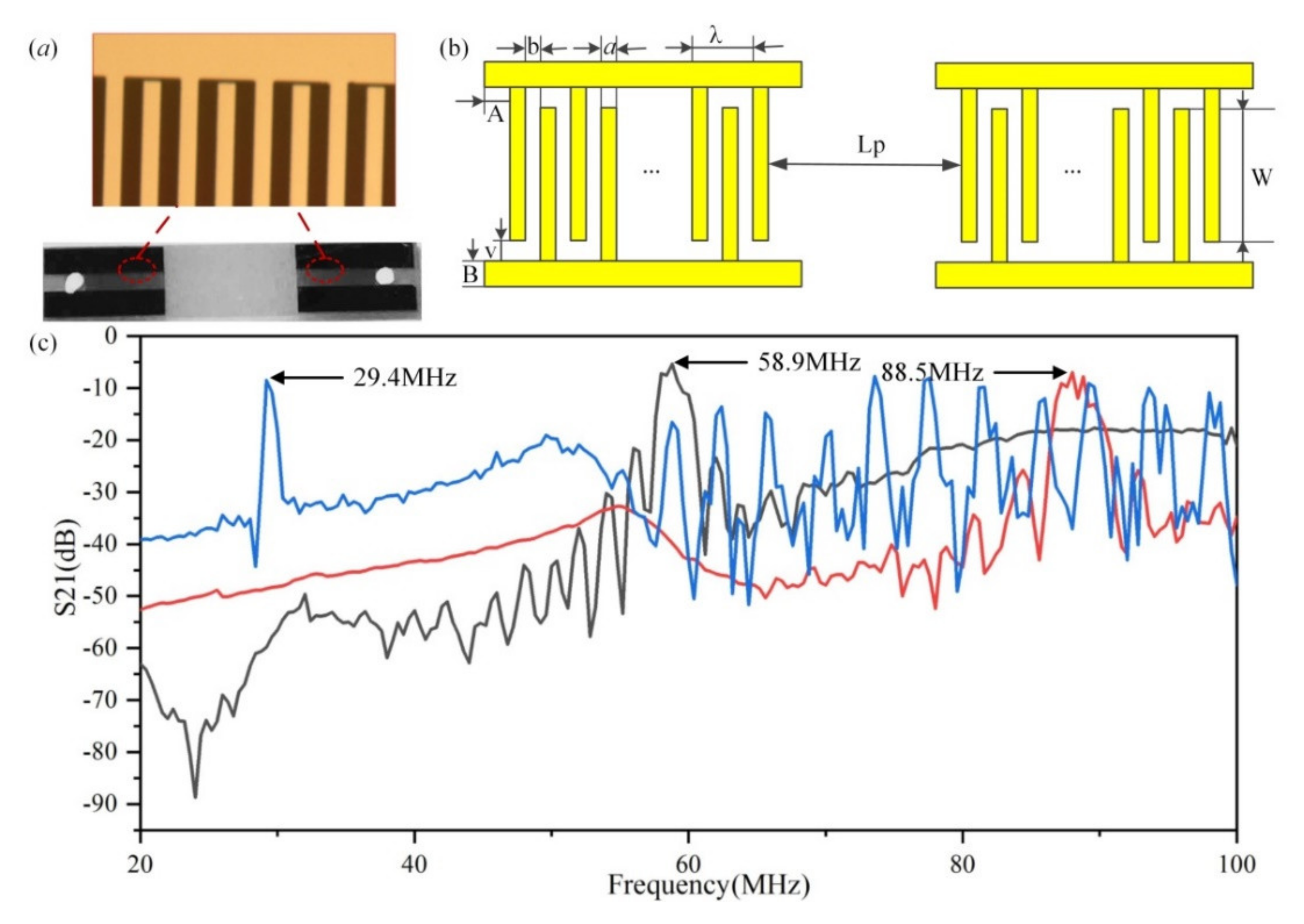
Figure 1. Image of the small-aperture-straight-electrode SAW devices and design parameters of the interdigital transducers (IDTs). (a) The diagram of a fabricated SAW device. (b) The structure and design parameters of IDTs. (c) The frequency resonant characteristic curve of the fabricated SAW devices.
Actuators 09 00005 g001
Figure 2. Schematic diagram of the SAW-microfluidic jetting system.
Actuators 09 00005 g002
Figure 3. A group of snapshots for droplet jetting phenomenon in a vertical capillary tube induced by SASE SAWs. The Figure in the dashed box is a schematic diagram of the interaction principle mechanism between traveling SAW and fluid. Figures (ah) in the bottom are the evolution of single droplet jetting and pinching-off.
Actuators 09 00005 g003
Figure 4. A group of snapshots for droplet jetting in vertical capillary tube with uneven liquid level.
Actuators 09 00005 g004
Figure 5. A group of snapshots for droplet jetting phenomenon in vertical capillary tube with 6 mm diameter.
Actuators 09 00005 g005
Figure 6. A group of snapshots for droplet jetting phenomenon in vertical capillary tube with different liquid level. (a) Jetting for low liquid level in a vertical capillary tube with an inner diameter of 3 mm and 5-μL deionized water. (b) Jetting for high liquid level in a vertical capillary tube with an inner diameter of 3 mm and 15-μL deionized water.
Actuators 09 00005 g006
Figure 7. Frequency effect on the interaction between SAW and deionized water loaded in a transparent plastic capillary tube with a dimension of 3.0 mm × 0.1 mm × 3.0 mm. (a) Relationship in single droplet jetting between applied RF threshold power and liquid volume at different frequencies. (b) Distribution of calculated SAW streaming force and interaction distance between SAW and fluid at different frequencies.
Actuators 09 00005 g007
Figure 8. Relationship between the dimension of the ejected microdroplet and liquid level in the capillary tube with the excitation frequency at 29.4 MHz and tube size at 3.0 mm × 0.1 mm × 3.0 mm.
Actuators 09 00005 g008
Table 1. Jetting and pinching off parameters from the experiments.
Frequency
(MHz)
Liquid Volume
(μL)
PD
(W)
Rj
(mm)
Uj
(m/s)
Werj
(mm)
vj
(m/s)
29.4830.43130.21390.27360.64000.1683
29.4102.60.38130.27460.39880.52270.1254
29.4122.050.36250.18880.17930.48360.1609
29.4141.80.34380.20820.20660.38230.0924
29.4161.50.30630.25520.27660.34140.1336
29.4181.40.28130.18560.13430.31670.0689