1. Introduction
Creating devices able to operate at the micrometre scale has been part of the scope of the vanguard of science and technology for many years. Using the same technology that has allowed the miniaturization of electronic circuits, it is possible to fabricate miniaturized systems composed of mechanical structures and electronic components, the so-called microelectromechanical systems (MEMS).
In recent years, sensors and actuators have been usually driven by electrostatic [
1], electromagnetic [
2], thermal [
3], piezoelectric [
4] and Lorentz forces [
5,
6]. The use of piezoelectric excitation is challenging, since a considerable voltage is needed to achieve practical forces or displacements. Nevertheless, in-plane piezoelectric actuators, using PZT (lead zirconate titanate) as a piezoelectric layer, have recently shown promising results: laser-machined [
7] and thick-film PZT-based actuators [
8] in the millimetre size range demonstrated displacements of 60 and 12 nm/V, while sub-millimetre-sized thin-film PZT-based actuators reached in-plane displacements as high as 300 nm/V [
9,
10,
11].
Actuators, in general, have achieved remarkable progress in many fields [
12,
13], being able to generate forces or displacements to perform scanning, tuning, manipulating, tactile sensing or delivering functions [
14,
15]. Tactile sensing might be one of the most complex sensing modalities compared to sight, hearing, smell, and taste, as it is not a simple transduction of one physical property into a bioelectric signal [
16]. In this field, contact resonance is a well-established technique, which allows for the determination of sample mechanical properties by tracking the resonance frequency of a structure modal vibration while interacting with the sample. The background of this technique was established by Kleesattel and Gladwell in 1968 [
17,
18,
19,
20]. Afterwards, Omata et al. used it at the micrometre level [
21,
22]; and Rabe deepened the understanding of the technique for atomic microscopy systems with publications that are a reference in the field [
23,
24]. In this case, a micro cantilever with a tip is used to sense information about the sample, including the force, roughness, and modulus of elasticity [
25,
26]. Nevertheless, in atomic force microscopy (AFM), the interaction force between the tip and the sample is obtained by detecting the deformation of the cantilever using a laser diode [
27,
28].
Over the last years, several works have been published related to this topic. For example, Fu et al. described a method for determining the modulus of elasticity using a sensor made of a piezoelectric bimorph cantilever, with a strain gauge for tactile sensing [
29]. More recently, Bertke et al. described a piezo-resistive silicon cantilever, with a phase-locked loop (PLL) system, for controlled micro-tactile measurements based on contact resonance spectroscopy [
30].
In this work, a piezoelectric PZT-based beam actuator was used as a tactile sensor in order to determine the modulus of elasticity of different materials with the help of low-cost driving electronic circuits. In this case, the actuator was first calibrated against a force sensor and mounted in a positioning stage to allow the approximation and the contact of the sensor tip with a set of target materials. Simultaneously, electrical measurements were performed using the resonator as part of a low-cost oscillator circuit, and the modulus of elasticity of the sample was derived from the contact resonant frequency curve of the cantilever–sample system. This method offers an effective, non-destructive and low-cost solution for tactile sensing compared to atomic force microscopy (AFM) techniques.
2. Materials and Methods
In this section, the bimorph actuators and their out-of-plane vibration modes, measurement setups and electronic circuits are described.
2.1. Lead Zirconate Titanate (PZT) Actuator
The PZT bimorph actuator used in this work is a low-cost and commercially available device of 15 × 1.5 × 0.6 mm
3 (see
Figure 1) [
31]. It was initially characterized with an impedance analyzer and a scanning laser vibrometer (Polytec MSV400) to detect the different out-of-plane vibration modes and to obtain the main resonance parameters, resonant frequency (f
r) and quality factor (Q) of each vibration mode. Following Leissa’s nomenclature, the vibration modes were designated as 10-mode and 20-mode according to the number of nodal lines in each direction [
32].
The results from impedance measurements are shown in
Table 1. As it can be observed, the measured quality factor in air is in the range of 15 to 20 for these vibration modes, this being a relatively low value compared to other state-of-the-art resonators [
33]. Nevertheless, the high conductance peak value (ΔG) along with the low resonant frequency of the 20-mode makes it suitable for the inclusion of the piezoelectric resonator in an oscillator circuit for a number of applications.
Once the 20 mode was selected as the appropriate vibration mode, it was analyzed with a scanning laser vibrometer for different excitation voltages in order to measure the maximum displacement of the actuator versus applied voltage (see
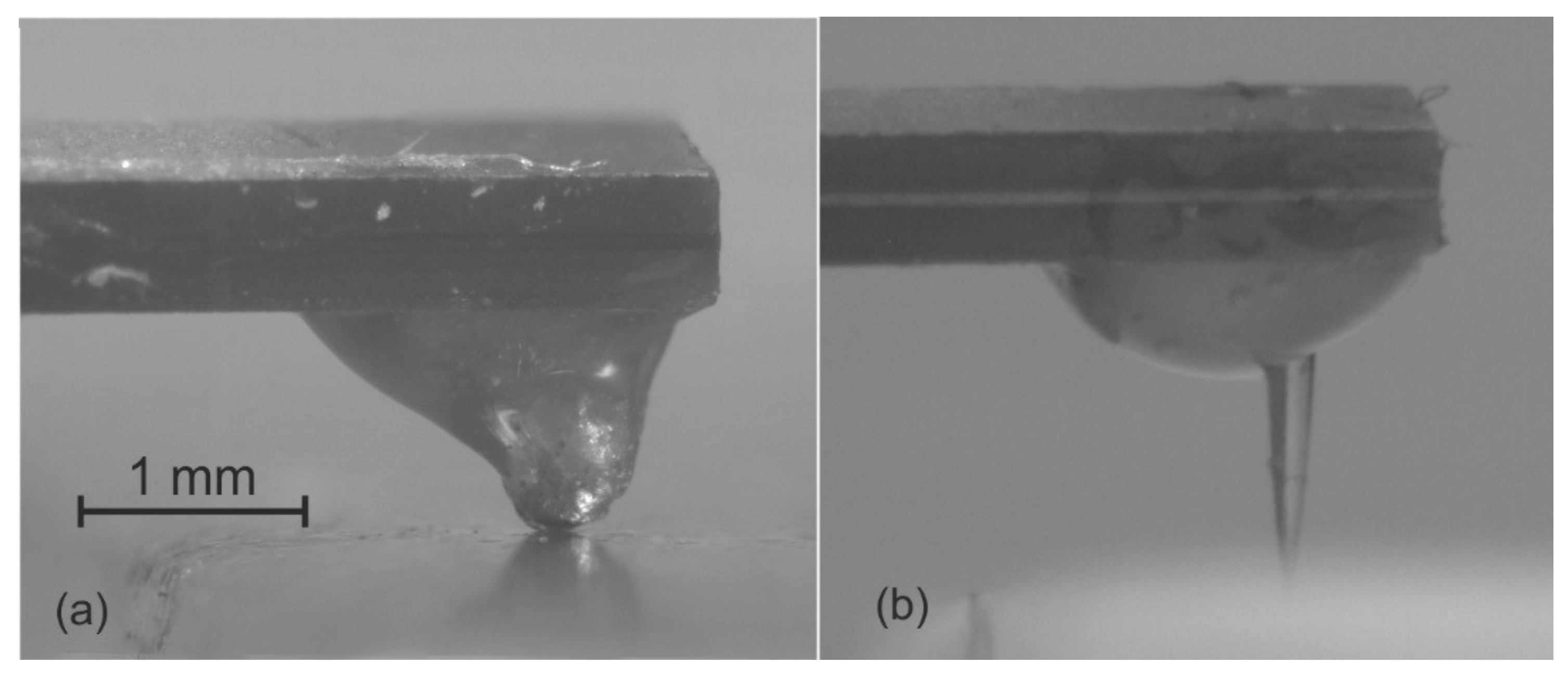
Table 2). As it can be observed, a linear relationship between the voltage and the displacement was obtained. As expected, the maximum displacement was measured in the resonator tip, which was used to contact the target material samples in our experiments. In order to check the influence of the tip on the modulus-of-elasticity sensing, two PZT actuators with different tips were employed in the measurements. In the named PZT-1 actuator, an aluminum tip was glued to the beam, while in the PZT-2 actuator a tungsten tip was used (see
Figure 2).
In the results presented in
Table 1, the beam boundary condition was clamped-free. Besides, in order to perform the elastic constant measurements, it was necessary to design a framework that implemented the clamped condition of the cantilever at one end. This framework, in which the beam’s end was introduced and glued with epoxy, was fabricated with a FDM (Fused Deposition Modeling) 3D printer to minimize possible vibrations. Once the bimorph actuator and tip were glued, an increase of the resonant frequency was observed as it can be seen in
Table 2, compared to
Table 1 for the 20-mode. This occurs because the effective length of the cantilever is reduced when introduced and bonded inside the 3D-printed frame. As it can be observed, the PZT-2 actuator presents a higher displacement per voltage applied compared to the PZT-1 actuator, as expected when the size and mass of the tip are lower in the former.
2.2. Measurement Setup
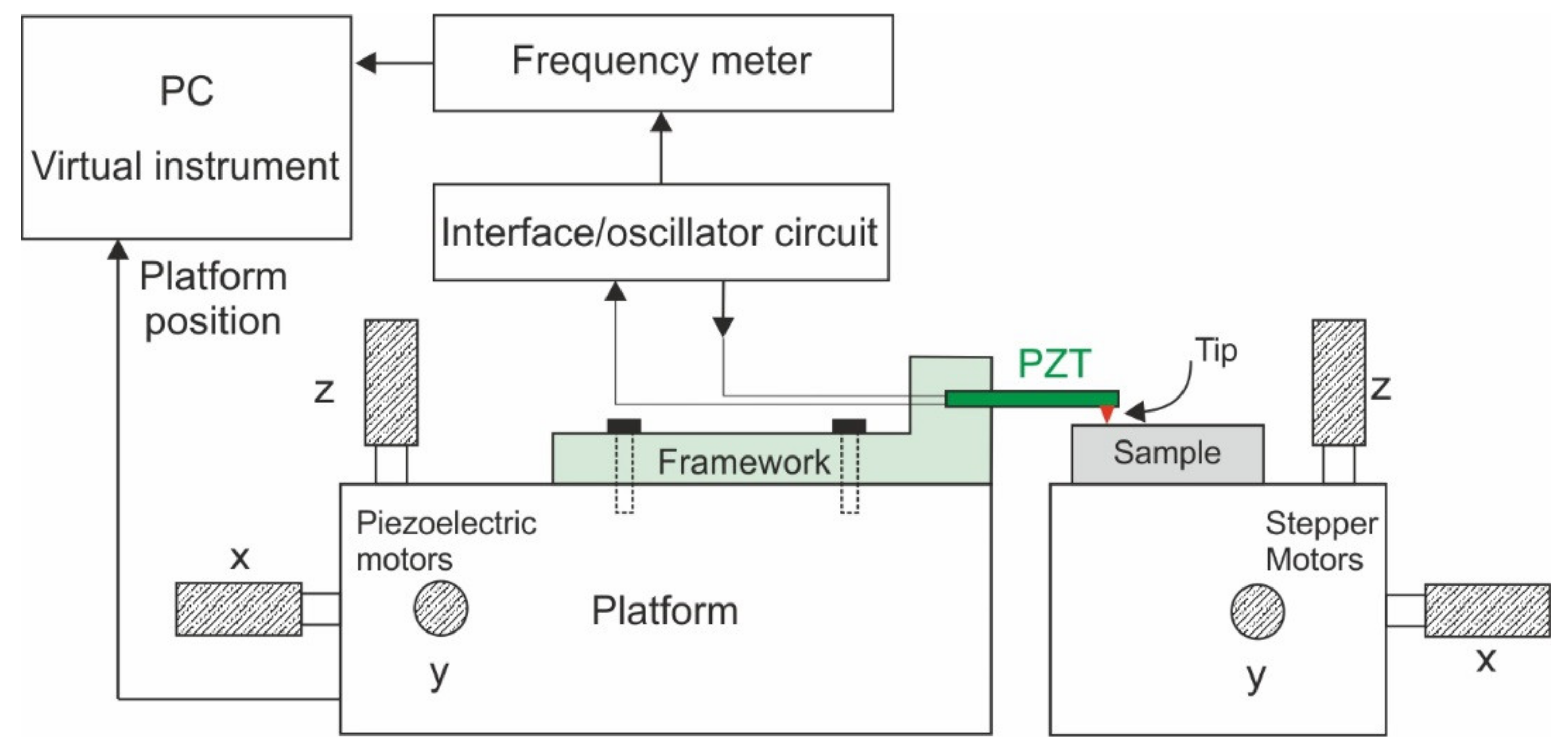
In order to perform the modulus of elasticity measurements and allow the approximation and contact of the cantilever tip, a positioning stage was implemented as displayed in
Figure 3. In this setup, the 3D-printed framework was attached to a platform controlled by six stepping motors that allow movement in any direction: three high-precision piezoelectric motors with a maximum displacement of 20 µm and three stepper motors that allow a coarse displacement of 5 mm. The approximation of the PZT actuator to the sample was performed with the help of the stepper motors, while the piezoelectric motors’ high-precision positioning feedback was used for the determination of the modulus of elasticity. In order to control the motors at the positioning stage and simultaneously obtain the resonance parameters, a virtual instrument (VI) was designed in
LabView from National Instruments [
34].
2.3. Low-Cost Electronic Circuits
In this section, the designed driving interface and oscillator circuits, for the open and closed-loop measurements described in
Section 3, are introduced.
2.3.1. Interface Circuit
Firstly, the behaviour of the resonator was tested by making open-loop measurements. These were performed using a lock-in amplifier to excite and collect the signal from the actuator within an interface circuit (see
Figure 4) [
35]. The main objective of the interface circuit is to reduce the parasitic effects of the resonator and to obtain an appropriate resonance curve for the later closed-loop measurements. Both, the PZT actuator and a parasitic compensating device (PZT compensation) were used simultaneously for actuation and sensing [
36].
The designed interface circuit uses an instrumentation amplifier (AD8428) to subtract the compensating device dielectric current (id) from that of the actuator (ipiezo + id), obtaining a voltage proportional to the piezoelectric current (ipiezo), which is proportional to the vibration amplitude, at the output of the instrumentation amplifier (Vout).
As it can be observed in
Figure 4, the compensation can be accurately tuned by implementing variable resistance (Rs) at the input of the instrumentation amplifier. The compensating device (PZT compensation) is nominally identical to the PZT actuator, but clamped all along its length, to prevent vibrations. Since the materials and dimensions in the compensating and actuator devices are nominally the same, they are expected to show similar electrical behavior with respect to their parasitic effects.
2.3.2. Oscillator Circuit
Once the parasitic effects of the resonator were minimized with the previous interface circuit, we included the actuator in an oscillator circuit scheme. The possibility of reducing the total size, cost and power consumption of the system makes the oscillator circuit a very interesting solution for any potential application scenario [
37,
38]. In addition, the reasonably good value of the admittance peak amplitude, along with the low natural frequency of the actuator, allowed for a great flexibility and simplicity in the design of the oscillator circuit.
In this case, the interface circuit was modified to meet the Barkhausen criterion when closing the loop between V
out and V
in, and the lock-in amplifier was removed. In order to achieve this, a higher gain in the instrumentation amplifier was applied, replacing the resistance that controls the gain amplifier by a capacitor (C
f) (see
Figure 4). This component acts as a low-pass filter and introduces the gain necessary to meet the Barkhausen criterion. Furthermore, the phase shift when closing the loop is 0°, since the instrumentation amplifier does not introduce any phase shift. This means that the oscillation frequency and the real resonance frequency of the actuator are equal.
Finally, when a stable oscillation is attained at the output (Vout), the frequency value can be easily tracked by a frequency counter (Agilent 53220a). This is controlled by the same virtual instrument that drives the positioning platform. In this case, 1000 samples were obtained in the 20 µm range of the piezoelectric motors, with a sample rate of 0.8 s.
3. Measurements and Results
3.1. Actuator Measurements
The analysis of the different samples was performed with the previously described low-cost electronic circuits in open and closed-loop schemes.
3.1.1. Open-Loop Measurements
Firstly, the behavior of the interface circuit (see
Figure 4) was tested in an open-loop configuration with the PZT-1 actuator. In order to perform these measurements, the platform and actuator were moved with the virtual instrument to approach the tip and identify the contact on a sample of polylactic acid material, commonly known as PLA (see
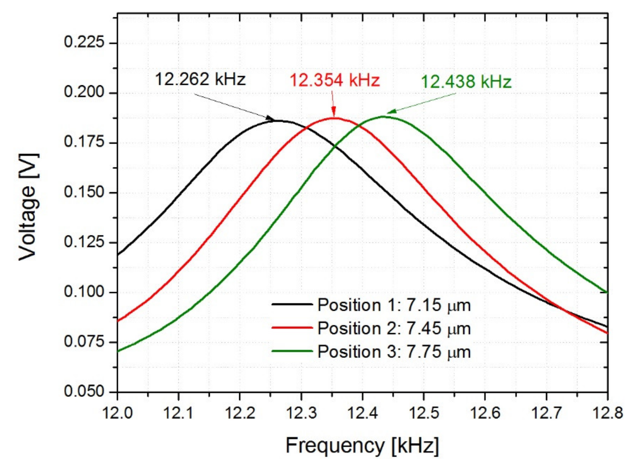
Table 3), frequently used in 3D printing. In this case, the lock-in amplifier performed the frequency sweep measurement during the contact approaching process. Once the actuator was brought into contact with the PLA sample, three open-loop measurements were completed by moving the platform between the positions 7.15 and 7.75 µm in the z-axis direction.
As it can be seen in
Figure 5, a higher force or displacement leads to an increase of the resonant frequency, indicating that the procedure is valid for the elastic-constant-sensing application. Although these open-loop measurements were only used as a validation step, it was also checked that the phase curve met the Barkhausen criterion for the oscillation of the resonator to start, a necessary requirement for the later implementation of the oscillator circuit.
3.1.2. Closed-Loop Measurements
Once the behavior of the actuator and the measurement setup was verified, different closed-loop measurements were performed using the previously described oscillator circuit (see
Section 2.3.2). In
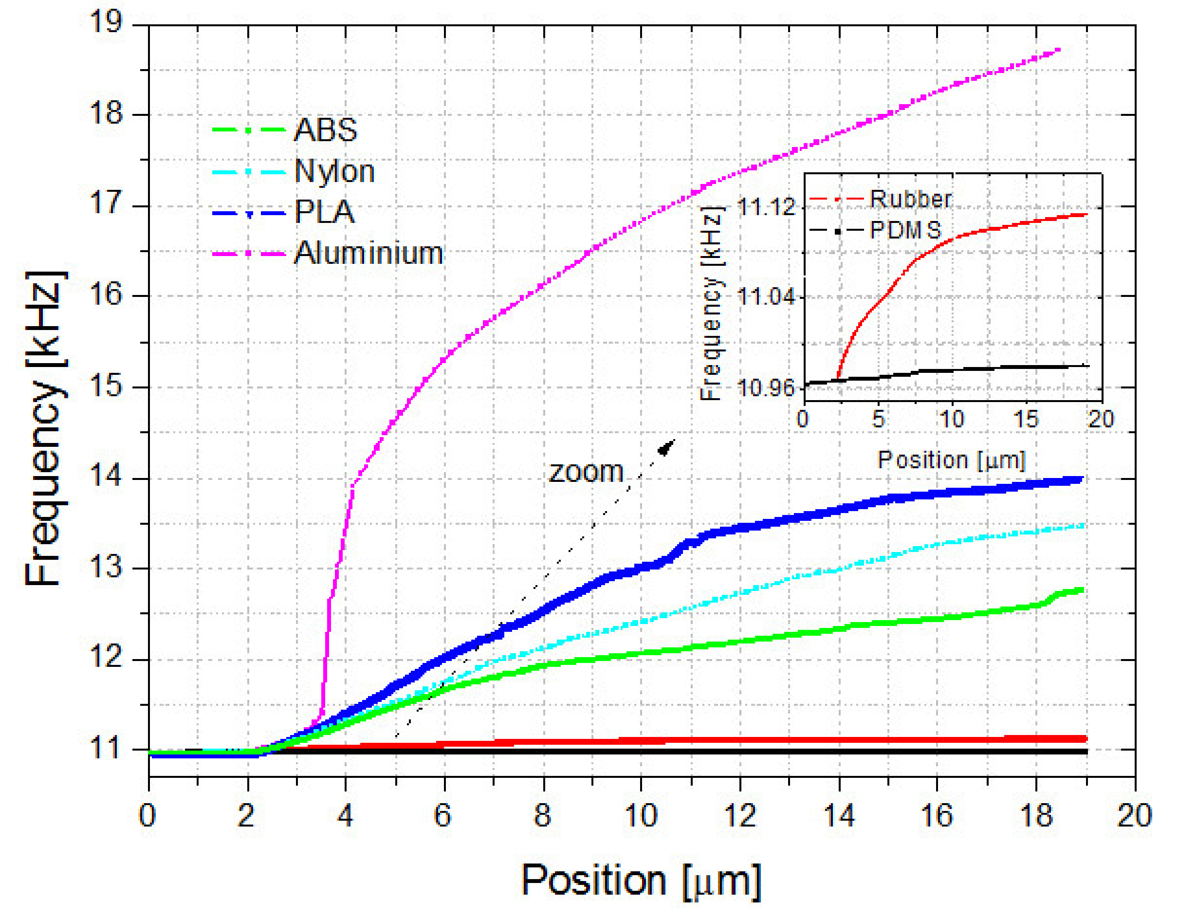
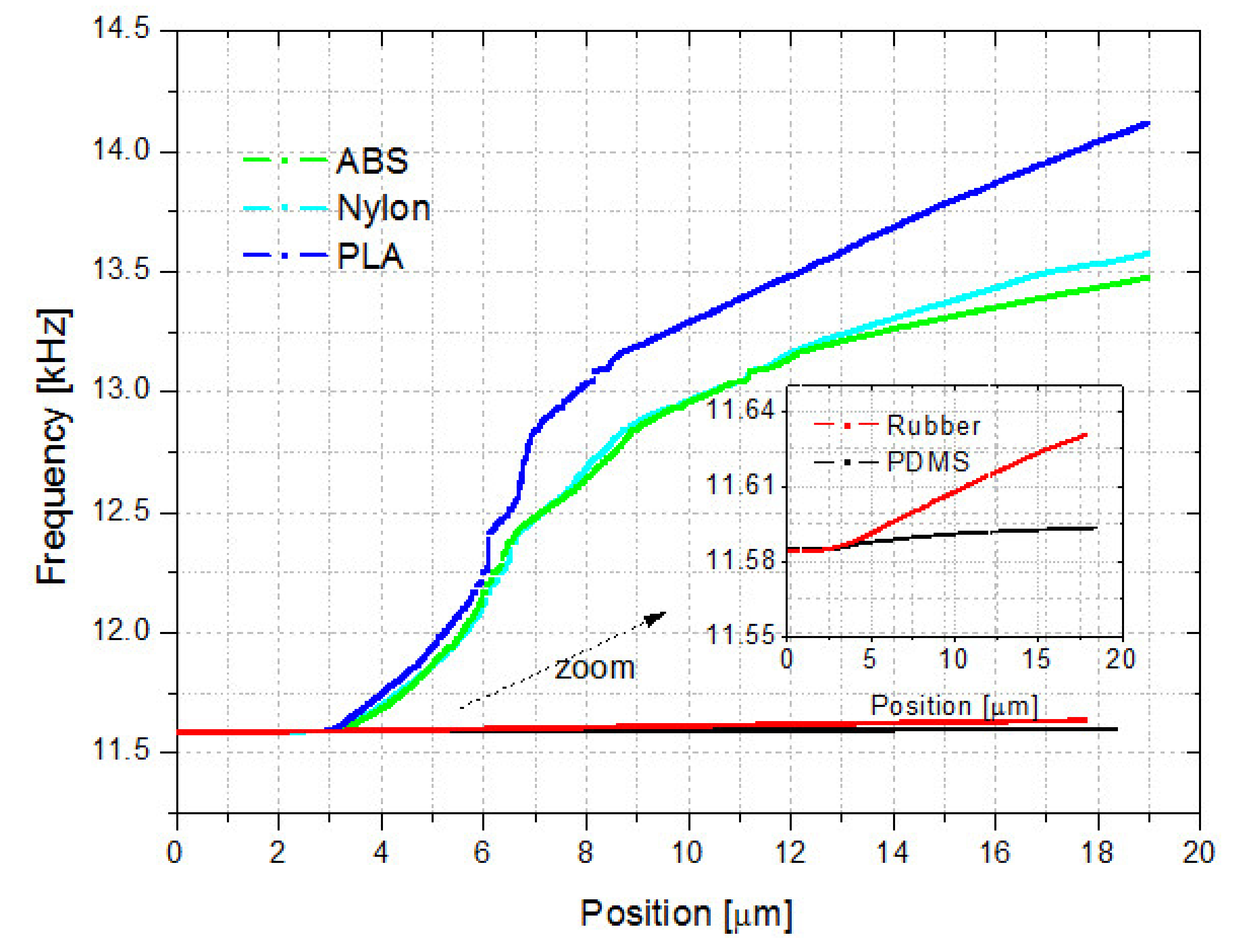
Table 3, the different materials are shown from lowest to highest modulus of elasticity and their reference values: PDMS, rubber, ABS, nylon, PLA and aluminum. As it can be seen, the PDMS and the rubber present a similar elastic constant. The same occurs for the ABS, Nylon and PLA samples. Nevertheless, it is possible to observe differences in the resonant frequency values for both resonators (see
Figure 6 and
Figure 7).
As it can be seen in
Figure 6 and
Figure 7, a higher force or displacement increases the resonant frequency, as was also verified with the open-loop measurements. In addition, the resonant frequency changes accordingly with the modulus of elasticity of the sample, indicating that the resonant frequency could be used as a valid parameter for the determination of the modulus of elasticity. As the results suggest, it would be necessary to implement a force control capable of monitoring the applied force on the sample surface. Nevertheless, in this work, an alternative solution was tested by taking as a reference the point where the tip makes contact with the target sample, and therefore the resonant frequency increases. This allowed us to compare the frequency measurements of different materials and also to estimate the applied force through the actuator calibration process described in
Section 3.2.
The procedure performed to obtain the modulus of elasticity of the samples can be summarized as follows. Firstly, the resonator is excited and brought into contact with the sample with a tip-target approaching process. After that, the resonator tip contacts the sample, the applied force is obtained from the position of the platform (see
Section 3.2) and the resonant frequency is tracked with the oscillator circuit and the frequency counter.
As it can be observed in the closed-loop measurements performed with the PZT-2 actuator, almost no difference in the resonant frequency value, during the initial displacement of approximately 4 µm of the positioning stage, is detected (see
Figure 7). This is due to the fact that the frequency shift observed during this displacement, which is similar for the different materials, may be attributed to the elasticity of the epoxy glue used to attach the tungsten tip to the actuator. Once the initial range is exceeded, the tip remains fixed to the actuator, being able to detect differences in its resonant frequency as the modulus of elasticity of the tungsten tip (450 GPa) is much greater than the modulus of elasticity of the actuator (33.3 GPa).
As it can be seen in
Figure 6 and
Figure 7, a higher resonant frequency was obtained for PLA, due to its higher elastic constant compared to ABS and nylon. In contrast, almost no differences were observed for PDMS and rubber, due to the low modulus of elasticity of these materials compared with the actuators and the tips. These results confirm the results of previous studies on AFM, where a high detection sensitivity, or stiffer or flexible cantilevers, are required for testing on samples with high or low modulus of elasticity, respectively [
47].
3.2. Actuator and Force Sensor Calibration
The main objective of this work was to demonstrate a simple method to obtain the modulus of elasticity of different materials, applying it to those typically used in 3D printing technology. For this reason, it is necessary to perform two different approaches in order to correlate the contact resonant frequency of the actuator with the applied force on the surface material, and its elastic properties.
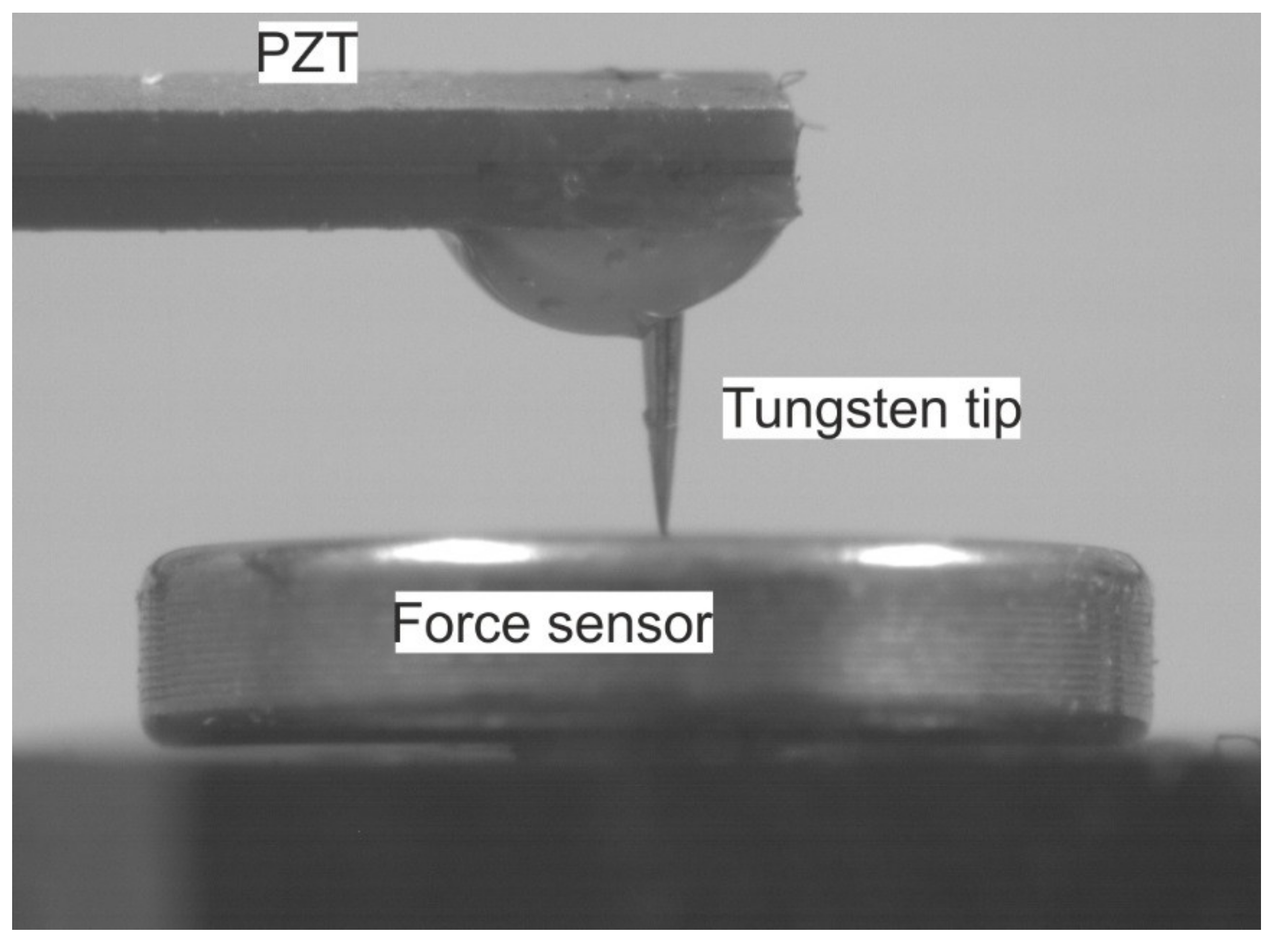
Firstly, the stiffness constant (K) of the PZT-2 actuator was measured, since this parameter is required for the determination of the modulus of elasticity (see
Section 3.3). In this case, a commercial force sensor (see
Figure 8) [
48] allowed us to obtain a linear relationship between its output voltage and the force applied by the piezoelectric beam when the positioning stage was shifted (see
Figure 9). According to the datasheet of the force sensor, this presents a sensitivity of 7.2 mV/V/N; since the force sensor is biased with a voltage of 10 V, we obtain a conversion factor of 72 mV/N. With this conversion factor we can finally obtain the stiffness constant (K) of the actuator. An average value of K, and the deviation obtained with five different measurements, leads to 1565 ± 138 N/m, similar to the value of 1520 N/m reported in the datasheet.
Once the stiffness contact is known, it is necessary to obtain the force applied by the actuator when the tip makes contact with the material to be analyzed. To do this, the actuator is excited with the electronics and brought into contact with the force sensor. In this case, when the resonance curve changes, indicating that the actuator has made contact with the sample, the position of the platform is taken as a reference. This approach allows us to estimate the force applied by the actuator over the sample just by sampling the position of the platform.
3.3. Modulus of Elasticity Sensing
In this section, the performance of the tactile sensor for the determination of the modulus of elasticity is carefully examined. Once the calibration of the PZT-2 actuator was performed, the modulus of elasticity of the different materials were obtained using the Hertz contact theory [
49,
50], following a procedure previously reported [
29].
In a first step, the modulus of elasticity of the PZT-2 actuator (
E) and the moment of inertia (
I) were calculated through Equations (1) and (2).
where
K is the stiffness constant previously obtained, with a value of 1565 N/m. In this case, the length of the cantilever beam is shorter due to the anchoring to the 3D-printed framework, being now of length (
l) 12 mm, width (
w) 1.5 mm and thickness (
t) 0.6 mm. Using this data, we could obtain a modulus of elasticity (
E) for the PZT actuator of 33.3 GPa.
In order to estimate the modulus of elasticity of the samples (Es in Equation (5)), it is necessary to first calculate the constants Cc and kt defined in Equations (3) and (4). Once the modulus of elasticity of the actuator was known, and taking into account that the density of the PZT actuator (ρ) is 7500 kg/m3, it was possible to estimate the constant Cc, obtaining a value of 0.0498 s1/2 (see Equation (3)).
The value of the constant
Cc presents different error sources, such as the dimensions and properties of the cantilever. In order to reduce the final error, the constant
Cc was calibrated through the following process. In this case, four different positions of the platform (7, 11, 15 and 18 µm) and the corresponding values of resonant frequency, force and modulus of elasticity for the ABS, nylon and PLA, were taken references in Equations (4) and (5) (see
Table 4).
In Equations (4) and (5),
Et represents the modulus of elasticity of the tungsten tip with a value of 450 GPa,
Es is the modulus of elasticity of the measured sample,
R is the radius of the tip with a value of 10 µm,
υs is the Poisson’s coefficient with a value of 0.35,
kt is the tip stiffness constant,
K is the cantilever stiffness constant,
fr is the contact measured resonant frequency and
F is the applied force. With all these data, and using Equations (4) and (5), it was possible to calibrate the constant
Cc obtaining a new value of 0.0458 s
1/2. Once this constant
Cc is known, the PZT actuator can be used to estimate the modulus of elasticity of different materials.
Table 4 displays a summary with the estimated and reference values for the modulus of elasticity.
4. Discussion
In this work, the modulus of elasticity, or Young’s modulus, of different materials was derived using a PZT actuator, a low-cost oscillator circuit and a positioning stage. Other previous publications suggest it is necessary to implement a force control or gauge deformation capable of monitoring the applied force and deformation of the actuator [
27,
29]. Nevertheless, in this work, an alternative solution was tested, by taking the point where the PZT actuator tip makes contact with the sample, and therefore the resonant frequency increases, as a reference, allowing us to compare the frequency measurements of different materials and also to estimate the applied force.
Another advantage of this work is that the designed setup, positioning stage and electronics could be easily applied to different actuators with out-of-plane vibration modes. In this case it would only be necessary to design a new 3D-printed framework to fix the actuator and to calibrate the actuator against the force sensor to obtain its stiffness constant. This approach would also make it possible to extend the application to different actuators, in order to analyze materials with different modulus of elasticity. Also noteworthy is the novelty of the electronics circuits implemented in this work, making it possible to reduce parasitic effects and to obtain an appropriate resonance curve for the oscillation of the piezoelectric actuator.
The procedure implemented to obtain the modulus of elasticity of the samples can be summarized as follows. First, the actuator, with a tip attached to its end, is excited near resonance and brought into contact with the sample while the resonance is assessed. Once the resonance curve indicates that the tip contacts the sample, the position of the platform is taken, and the resonant frequency is tracked with the oscillator circuit and the frequency counter.
As indicated in previous studies on AFM, to get a high detection sensitivity, stiff or flexible actuators are required for testing on samples with a high or low modulus of elasticity, respectively [
47]. This fact was also observed in our results. For example, a higher resonant frequency was obtained for the PLA due to its higher elastic constant. On the contrary, almost no differences were observed for the PDMS and rubber due to the low modulus of elasticity of these materials compared with the PZT actuator.
In this work, the modulus of elasticity was obtained through the Hertz contact theory, obtaining a resolution, through the measured frequency values for different positions of the platform, of 0.129 GPa in the worst case. As it can be observed in
Table 4, the estimated modulus of elasticity is in the range of the reference values published in previous work [
40,
41,
42,
43,
44,
45,
51,
52]. Nevertheless, the deviation of the modulus of elasticity for the ABS may be higher if compared with the average of published reference values. There are several reasons that could explain this behavior. The reference values cannot be fairly compared with our estimated values since the method developed in our work is based on a dynamic procedure limited to a reduced area and deformation, and not to the whole sample [
53]. This conclusion has also been observed in other works where large deviations were obtained in the estimation of the modulus of elasticity between the ABS filament itself and the 3D-printed sample [
42], where the data obtained from tensile tests of the filaments were also only qualitatively consistent with those provided by the manufacturer. Another reason behind the deviations with the reference values is the lack of standard test methods for the determination of the mechanical properties of parts manufactured using FDM. For example, the standards ASTM D638 [
54] and D790 [
53] may be applied for testing tensile and flexural specimens, respectively [
43].
Although one of the goals of this work was to estimate the Young’s modulus of the different samples, further investigation could be necessary to check the deviation with different measurement methods, and the viability of the piezoelectric actuator with different materials and setup.
5. Conclusions
In conclusion, a PZT bimorph actuator was tested for the determination of the modulus of elasticity, using low-cost electronic circuits based on an interface and oscillator circuit, and obtaining an accurate performance. For this reason, the PZT actuator along with the positioning stage can be considered an effective and non-destructive solution for the determination of the modulus of elasticity and sample characterization. In this case, the estimates of the modulus of elasticity of ABS, nylon and PLA were in the range of the reference values published in previous works, and a resolution of 0.129 GPa was obtained in the worst case. Furthermore, sample information such as the position, orientation, and surface topography could also be obtained by adding scanning functionality to the testing platform.
Author Contributions
Investigation, J.T. and J.L.S.-R; Project administration, J.L.S.-R.; Supervision, V.R.-D. and J.H.-G.; Validation, J.T.; Writing—original draft, J.T.; Writing—review & editing, J.T., V.R.-D., J.H.-G. and J.L.S.-R. All authors have read and agreed to the published version of the manuscript.
Funding
This research was funded by the European Regional Development Funds through projects RETOS RTI2018-094960-B-I00 and regional JCCLM SBPLY/17/180501/000139.
Conflicts of Interest
The authors declare no conflict of interest. The funders had no role in the design of the study; in the collection, analyses, or interpretation of data; in the writing of the manuscript, or in the decision to publish the results.
References
- Grade, J.D.; Jerman, H.; Kenny, T.W. Design of Large Deflection Electrostatic Actuators. J. Microelectromech. Syst. 2001, XX, 1–10. [Google Scholar] [CrossRef]
- Ko, J.S.; Lee, M.L. Development and application of laterally driven electromagnetic microactuator. Appl. Phys. Lett. 2002, 81, 547–549. [Google Scholar] [CrossRef]
- Qui, J.; Lang, J.H.; Slocum, A.H.; Strümpler, R. A high-current electrothermal bistable MEMS relay. In Proceedings of the Sixteenth Annual International Conference on Micro Electro Mechanical Systems, Kyoto, Japan, 23 January 2003; pp. 64–67. [Google Scholar]
- Manzaneque, T.; Ruiz-Díez, V.; Hernando-García, J.; Ababneh, A.; Al-Omari, A.N.; Kucera, M.; Bittner, A.; Schmid, U.; Seidel, H.; Sánchez-Rojas, J.L. Piezoelectric in-plane microplate resonators based on contour and flexure-actuated modes. Microsyst. Technol. 2014, 20, 691–699. [Google Scholar] [CrossRef]
- Lee, F.Y.; Tang, T.L.; Fang, W. Development of a novel dual-axis large-displacement microstage using Lorentz force actuators and curved-beam springs. Procedia Eng. 2011, 25, 689–692. [Google Scholar] [CrossRef][Green Version]
- Lv, X.D.; Wei, W.W.; Mao, X.; Yang, J.L.; Yang, F.H. A linear low driving voltage mems actuator with large lateral stroke driven by Lorentz force. In Proceedings of the 2015 Transducers—2015 18th International Conference on Solid-State Sensors, Actuators and Microsystems (TRANSDUCERS), Anchorage, AK, USA, 21–25 June 2015; pp. 2117–2120. [Google Scholar]
- Leang, K.K.; Fleming, A.J. High-speed serial-kinematic SPM scanner: Design and drive considerations. Asian J. Control 2009, 11, 144–153. [Google Scholar] [CrossRef]
- Aktakka, E.E.; Peterson, R.L.; Najafi, K. A 3-DOF piezoelectric micro vibratory stage based on bulk-PZT/silicon crab-leg suspensions. In Proceedings of the 2013 IEEE 26th International Conference on Micro Electro Mechanical Systems (MEMS), Taipei, Taiwan, 20–24 January 2013; pp. 576–579. [Google Scholar]
- Conway, N.J.; Kim, S.-G. Large Strain, Piezoelectric, in-Plane Micro-Actuator. In Proceedings of the 17th IEEE International Conference on Micro Electro Mechanical Systems. Maastricht MEMS 2004 Technical Digest, Maastricht, The Netherlands, 25–29 January 2004; pp. 454–457. [Google Scholar]
- Oldham, K.R.; Pulskamp, J.S.; Polcawich, R.G.; Dubey, M. Thin-film PZT lateral actuators with extended stroke. J. Microelectromech. Syst. 2008, 17, 890–899. [Google Scholar] [CrossRef]
- Yoshida, S.; Wang, N.; Kumano, M.; Kawai, Y.; Tanaka, S.; Esashi, M. Fabrication and characterization of laterally-driven piezoelectric bimorph MEMS actuator with sol-gel-based high-aspect-ratio PZT structure. In Proceedings of the 2013 IEEE 26th International Conference on Micro Electro Mechanical Systems (MEMS), Taipei, Taiwan, 20–24 January 2013. [Google Scholar]
- Howe, R.T.; Muller, R.S.; Gabriel, K.J.; Trimmer, W.S.N. Silicon micromechanics: Sensors and actuators on a chip. IEEE Spectr. 1990, 27, 29–31. [Google Scholar] [CrossRef]
- Fujita, H. Microactuators and micromachines. Proc. IEEE 1998, 86, 1721–1732. [Google Scholar] [CrossRef]
- Panchawagh, H.V.; Faheem, F.F.; Herrmann, C.F.; Serrell, D.B.; Finch, D.S.; Mahajan, R.L. Packaging of in-plane thermal microactuators for BioMEMS applications. In Proceedings of the American Society of Mechanical Engineers, Micro-Electro Mechanical Systems Division, (Publications) MEMS, Oahu, Hawaii, 5 November 2005. [Google Scholar]
- Eltagoury, Y.M.; Soliman, M.; Al-Otaibi, M.; Sabry, Y.M.; Sadek, M.; Khalil, D. In-plane comb-drive actuator with high frequency-displacement product for micro-optical bench applications. In Proceedings of the International Conference on Optical MEMS and Nanophotonics, Glasgow, UK, 17–21 August 2014. [Google Scholar]
- Lee, M.H.; Nicholls, H.R. Review Article Tactile sensing for mechatronics: A state of the art survey. Mechatronics 1999, 9, 1–31. [Google Scholar] [CrossRef]
- Kleesattel, C.; Gladwell, G.M.L. The contact-impedance meter 1. Ultrasonics 1968, 6, 175–180. [Google Scholar] [CrossRef]
- Gladwell, G.M.L.; Kleesattel, C. The contact-impedance meter 2. Ultrasonics 1968, 6, 244–251. [Google Scholar] [CrossRef]
- Kleesattel, C.; Gladwell, G.M.L. The contact-impedance meter 3. Ultrasonics 1969, 7, 57–62. [Google Scholar] [CrossRef]
- Kleesattel, C. Contact impedance meter. Part IV. Ultrasonics 1970, 8, 39–48. [Google Scholar] [CrossRef]
- Omata, S.; Terunuma, Y. New tactile sensor like the human hand and its applications. Sens. Actuators A. Phys. 1992, 35, 9–15. [Google Scholar] [CrossRef]
- Murayama, Y.; Omata, S. Fabrication of micro tactile sensor for the measurement of micro-scale local elasticity. Sens. Actuators A Phys. 2004, 109, 202–207. [Google Scholar] [CrossRef]
- Rabe, U.; Janser, K.; Arnold, W. Vibrations of free and surface-coupled atomic force microscope cantilevere: Theory and experiment. Rev. Sci. Instrum. 1996, 67, 3281–3293. [Google Scholar] [CrossRef]
- Rabe, U.; Arnold, W. Acoustic microscopy by atomic force microscopy. Appl. Phys. Lett. 1994, 64, 1493. [Google Scholar] [CrossRef]
- Zhou, X.; Fu, J.; Li, Y.; Li, F. Nanomechanical mapping of glass fiber reinforced polymer composites using atomic force acoustic microscopy. J. Appl. Polym. Sci. 2014, 131. [Google Scholar] [CrossRef]
- Rabe, U.; Kopycinska, M.; Hirsekorn, S.; Muñoz-Saldaña, J.; Schneider, G.A.; Arnold, W. High-resolution characterization of piezoelectric ceramics by ultrasonic scanning force microscopy techniques. J. Phys. D. Appl. Phys. 2002, 35, 2621–2635. [Google Scholar] [CrossRef]
- Monclus, M.A.; Young, T.J.; Di Maio, D. AFM indentation method used for elastic modulus characterization of interfaces and thin layers. J. Mater. Sci. 2010, 45, 3190–3197. [Google Scholar] [CrossRef]
- Bhushan, B.; Koinkar, V.N. Nanoindentation hardness measurements using atomic force microscopy. Appl. Phys. Lett. 1994, 64, 1653–1655. [Google Scholar] [CrossRef]
- Fu, J.; Li, F. A forefinger-like tactile sensor for elasticity sensing based on piezoelectric cantilevers. Sens. Actuators A Phys. 2015, 234, 351–358. [Google Scholar] [CrossRef]
- Bertke, M.; Fahrbach, M.; Hamdana, G.; Xu, J.; Wasisto, H.S.; Peiner, E. Contact resonance spectroscopy for on-the-machine manufactory monitoring. Sens. Actuators A Phys. 2018, 279, 501–508. [Google Scholar] [CrossRef]
- Rs Pro. Piezoelectric Ceramic Bimorph Element. Available online: https://docs-emea.rs-online.com/webdocs/1582/0900766b81582396.pdf (accessed on 2 February 2020).
- Leissa, A.W. Vibration of Plates; Scientific and Technical Information Division, National Aeronautics and Space Administration: Washington, DC, USA, 1969. [Google Scholar]
- Toledo, J.; Ruiz-díez, V.; Pfusterschmied, G.; Schmid, U.; Sánchez-rojas, J.L. Flow-through sensor based on piezoelectric MEMS resonator for the in-line monitoring of wine fermentation. Sens. Actuators B. Chem. 2017, 254, 291–298. [Google Scholar] [CrossRef]
- LabView, National Instruments. Available online: https://www.ni.com/es-es/shop/labview.html (accessed on 2 February 2020).
- Toledo, J.; Manzaneque, T.; Ruiz-Díez, V.; Kucera, M.; Pfusterschmied, G.; Wistrela, E.; Schmid, U.; Sánchez-Rojas, J.L. Piezoelectric resonators and oscillator circuit based on higher-order out-of-plane modes for density-viscosity measurements of liquids. J. Micromech. Microeng. 2016, 26, 084012. [Google Scholar] [CrossRef]
- Kucera, M.; Hofbauer, F.; Wistrela, E.; Manzaneque, T.; Ruiz-Díez, V.; Sánchez-Rojas, J.L.; Bittner, A.; Schmid, U. Lock-in amplifier powered analogue Q-control circuit for self-actuated self-sensing piezoelectric MEMS resonators. Microsyst. Technol. 2014, 20, 615–625. [Google Scholar] [CrossRef]
- Toledo, J.; Ruiz-Díez, V.; Bertke, M.; Wasisto, H.S.; Peiner, E.; Sánchez-Rojas, J.L. Piezoelectric MEMS resonators for cigarette particle detection. Micromachines 2019, 10, 145. [Google Scholar] [CrossRef]
- Toledo, J.; Ruiz-Díez, V.; Pfusterschmied, G.; Schmid, U.; Sánchez-Rojas, J.L. Characterization of oscillator circuits for monitoring the density-viscosity of liquids by means of piezoelectric MEMS microresonators. In Proceedings of the Smart Sensors, Actuators, and MEMS VIII, Barcelona, Spain, 8–11 May 2017. [Google Scholar]
- Wang, Z.; Volinsky, A.A.; Gallant, N.D. Crosslinking effect on polydimethylsiloxane elastic modulus measured by custom-built compression instrument. J. Appl. Polym. Sci. 2014, 131. [Google Scholar] [CrossRef]
- Engineering ToolBox. Young’s Modulus—Tensile and Yield Strength for Common Materials. Available online: https://www.engineeringtoolbox.com/young-modulus-d_417.html (accessed on 29 January 2020).
- Acrylonitrile Butadiene Styrene (ABS) and its Features. Available online: https://omnexus.specialchem.com/selection-guide/acrylonitrile-butadiene-styrene-abs-plastic (accessed on 3 March 2020).
- Rodríguez-Panes, A.; Claver, J.; Camacho, A.M. The influence of manufacturing parameters on the mechanical behaviour of PLA and ABS pieces manufactured by FDM: A comparative analysis. Materials 2018, 11, 1333. [Google Scholar] [CrossRef]
- Chacón, J.M.; Caminero, M.A.; García-Plaza, E.; Núñez, P.J. Additive manufacturing of PLA structures using fused deposition modelling: Effect of process parameters on mechanical properties and their optimal selection. Mater. Des. 2017, 124, 143–157. [Google Scholar] [CrossRef]
- Kotlinski, J. Mechanical properties of commercial rapid prototyping materials. Rapid Prototyp. J. 2014, 20, 499–510. [Google Scholar] [CrossRef]
- Lanzotti, A.; Grasso, M.; Staiano, G.; Martorelli, M. The impact of process parameters on mechanical properties of parts fabricated in PLA with an open-source 3-D printer. Rapid Prototyp. J. 2015, 21, 604–617. [Google Scholar] [CrossRef]
- ASM International. Properties and Selection: Irons, Steels, and High-Performance Alloys. In ASM Handbook; ASM International: Materials Park, OH, USA, 1993. [Google Scholar]
- Turner, J.A.; Wiehn, J.S. Sensitivity of flexural and torsional vibration modes of atomic force microscope cantilevers to surface stiffness variations. Nanotechnology 2001, 12, 322. [Google Scholar] [CrossRef]
- FSG Series Force Sensors. Available online: https://sensing.honeywell.com/fsg005wnpb-force-sensors2 (accessed on 19 March 2020).
- Johnson, K.L. One hundred years of hertz contact. Proc. Inst. Mech. Eng. 1982, 196, 363–378. [Google Scholar] [CrossRef]
- MacHado, M.; Moreira, P.; Flores, P.; Lankarani, H.M. Compliant contact force models in multibody dynamics: Evolution of the Hertz contact theory. Mech. Mach. Theory 2012, 53, 99–121. [Google Scholar] [CrossRef]
- De León, A.S.; Domínguez-Calvo, A.; Molina, S.I. Materials with enhanced adhesive properties based on acrylonitrile-butadiene-styrene (ABS)/thermoplastic polyurethane (TPU) blends for fused filament fabrication (FFF). Mater. Des. 2019, 182, 108044. [Google Scholar] [CrossRef]
- Casavola, C.; Cazzato, A.; Moramarco, V.; Renna, G. Mechanical behaviour of ABS-Fused Filament Fabrication compounds under impact tensile loadings. Materials 2019, 12, 1295. [Google Scholar] [CrossRef]
- ASTM International. D 790—Standard Test Method for Flexural Properties of Unreinforced and Reinforced Plastics and Electrical Insulation Materials; ASTM: West Conshohocken, PA, USA, 2015. [Google Scholar]
- ASTM International. D638—Standard Test Method for Tensile Properties of Plastics; ASTM International: West Conshohocken, PA, USA, 2014. [Google Scholar] [CrossRef]
© 2020 by the authors. Licensee MDPI, Basel, Switzerland. This article is an open access article distributed under the terms and conditions of the Creative Commons Attribution (CC BY) license (http://creativecommons.org/licenses/by/4.0/).

