1. Introduction
The rheological properties of magnetorheological (MR) fluid can be tuned using magnetic fields. The unique rheological behavior offers various advantages that have resulted in the development of a variety of devices such as the MR damper, MR brake, MR valve, and MR clutch. These devices are called semi-active actuators as they can increase the energy dissipation only by applying external stimuli. Among these devices, the MR damper can be considered to be the most popular one owing to its successful application and penetration in the commercial automotive market. Numerous studies have identified the critical features of the MR damper, such as the controllable dynamic range of damping force, rapid adjustment response, and low energy consumption [
1,
2,
3,
4]. The initial implementation of the MR damper was in the automotive industry [
5,
6,
7]; more recently, it has penetrated other sectors, including aerospace [
8,
9], marine structure [
10], military [
11,
12], biomedical devices [
13,
14], home appliances [
15], railway [
16,
17,
18], and civil engineering [
19,
20,
21]. The fundamental principle of the MR damper is similar to that of the conventional passive damper, which dissipates kinetic energy as heat through the flow restriction mechanism. The restriction of the fluid flow generates a reaction force perceived as a damping force [
7,
22,
23,
24,
25]. In the conventional passive damper, the flow restriction is caused by the piston orifice acting as a fixed valve. Similarly, the flow restriction concept is utilized in the MR damper, except that the orifice is replaced by magnetically induced flow channels known as the MR valve. The purpose of the MR valve is to restrict the flow by changing the rheological properties of the MR fluid locally in the magnetic channel. The changes in the rheological properties are proportional to the strength of the magnetic field that is then induced in the magnetic channel. Thus, the flow restriction can be continuously regulated using the controlled magnetic field strength in the MR valve. As a result, the perceived damping force can also be continuously regulated or controlled depending on the intensity of the magnetic field [
15,
26,
27].
The valve installation in an MR damper may be categorized into two types: a damper with an internal valve [
13,
26,
28,
29] and a damper with a bypass valve [
30,
31,
32]. The internal-valve type typically integrates the valve with the damper piston, similar to the orifice installation of the conventional passive damper [
28]. The MR damper designed on the basis of the internal-valve type can provide compact structural arrangements in numerous applications and operations. Unsal [
28] integrated a valve into the piston of the MR damper with the internal coils to improve the stroke length and heat dissipation from the inner coils. Dougroz et al. [
29] and Chen et al. [
13] introduced a new design concept of MR damper using an external coil equipped with the internal valve. However, the design method with the internal valve type is likely to cause several disadvantages, including limited space available for MR valve installation, the complexity of wiring, and the risk of thermal buildup from the immersed valve [
4]. Moreover, the fabrication process of the MR damper with the internal valve is significantly complex in terms of assembly and maintenance. In contrast, the MR damper with the bypass-valve configuration has no embedded structures in the piston [
30,
32]. The piston of the MR damper featuring the bypass-valve configuration is wholly sealed similar to the hydraulic cylinder used in conventional passive dampers. As a result, the exchange of MR fluid between the high-pressure and low-pressure chambers must bypass through the channel outside of the cylinder where the valve is located or placed. With the separation between the valve and piston, the installation and maintenance process of an MR damper is substantially more convenient than that of the MR damper with the internal-valve structure in the piston. That is, the valve placement or replacement is relatively more accessible without the necessity of disassembling all the components. In addition, the following benefits can be achieved from the MR damper with the bypass-valve structure. A less stringent constraint of the valve dimension is feasible as it is not directly limited by the size of the piston and cylinder. A larger stroke and excitation amplitude can be generated [
32], and a higher damping force in a small volume can be achieved [
32,
33,
34]. However, the size of the MR damper with the bypass-valve component may be increased when a large impulsive force is imposed on the system. As a result, it is likely to be highly challenging to appropriately install the MR damper in the restricted space. This problem results in the demand for structural reconfiguration of the bypass-valve-based MR dampers. Therefore, a new design concept of the MR damper with the bypass-valve structure needs to be explored to reduce the structure size while maintaining the advantages mentioned above.
In this study, a new concentric design structure of a bypass MR damper is proposed to achieve structural compactness by relocating the bypass valve in line with the main damper cylinder. The technical novelty of this study is in the presentation of a new design structure of a bypass MR damper with a concentric installation arrangement. This design provides the benefits of bypass valve arrangement in terms of better accessibility to the valve for easy maintenance as well as the performance flexibility, as a wider selection of MR valves can be used. At the same time, the concentric design also reduces the bulkiness drawbacks of the bypass valve as the valve placement consumes less width than the conventional bypass arrangement. In particular, the serpentine flux type valve is chosen to be used as the bypass valve. In the initial stage, an analytical damping model with the serpentine flux is derived. In the second design stage, the conceptual drawing of the MR damper is produced to evaluate the sizing issue using the analytical model and magnetic flux analysis. Then, the field-dependent damping force is analyzed by incorporating the yield stress of the MR fluid. Subsequently, a prototype of MR damper is fabricated by considering the volume size of the conventional MR damper and tested using the dynamic test machine. The field-dependent damping forces are measured and evaluated as a function of the current input. The results of the analytical model are then validated using the measurement results to evaluate the consistency between the measured and simulated damping force values.
2. Design Assessment
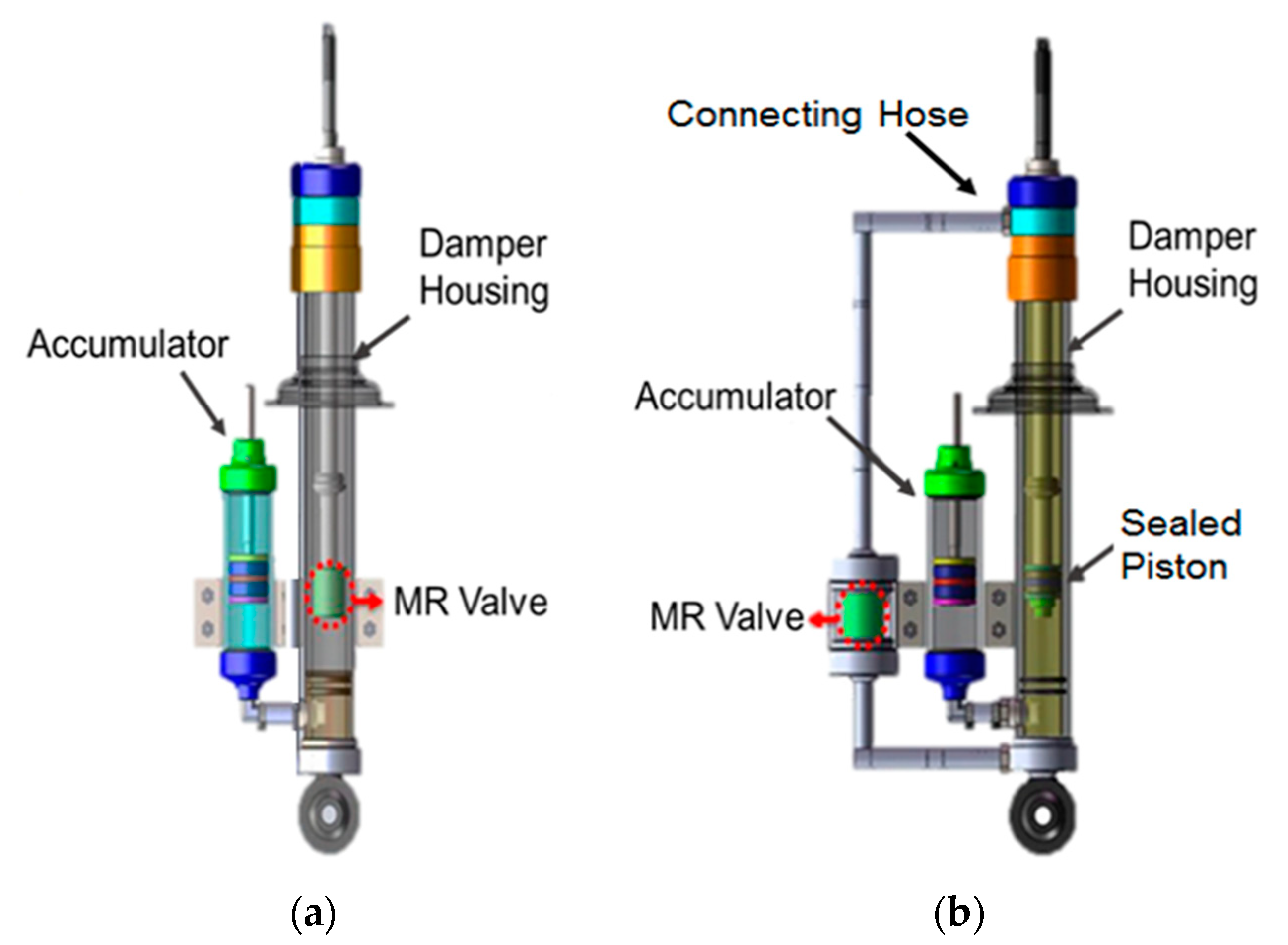
Figure 1 illustrates a comparison between the conventional internal-valve type MR damper and the conventional bypass type MR damper. Both valves operate in a similar manner where, during compression (downward motion), the MR fluid in the lower chamber (compression chamber) is pressurized and forced to flow to the upper chamber (extension chamber) and in a reverse flow direction during extension. Both types are also equipped with an accumulator, as both are a single-ended type damper, to balance the volume change during the compression and extension of the damper [
31]. The main difference is that in the internal-valve type, the valve is attached to the piston, while in the bypass type, the valve is normally embedded in the bypass conduit outside the cylinder. Each type has its benefits and weaknesses and an illustration of a similar scenario can be used to compare them. Assume that these two configurations have the same cylinder diameter of 8 cm, a valve diameter of 5 cm, an accumulator diameter of 8 cm and a stroke length of 10 cm. The internal-valve type will have an overall span range requirement of at least 16 cm to accommodate the cylinder and the accumulator. Meanwhile, the bypass type will require at least 21 cm of span range to accommodate the cylinder, accumulator and the bypass valve. On the other hand, as the internal-type places the valve inside the cylinder and attached to the piston, the room for the valve is very limited and tends to shorten the stroke. The bypass type, in this case, has the benefit of placing the valve outside the cylinder, which allows it to have more room for the valve and does not obstruct the stroke.
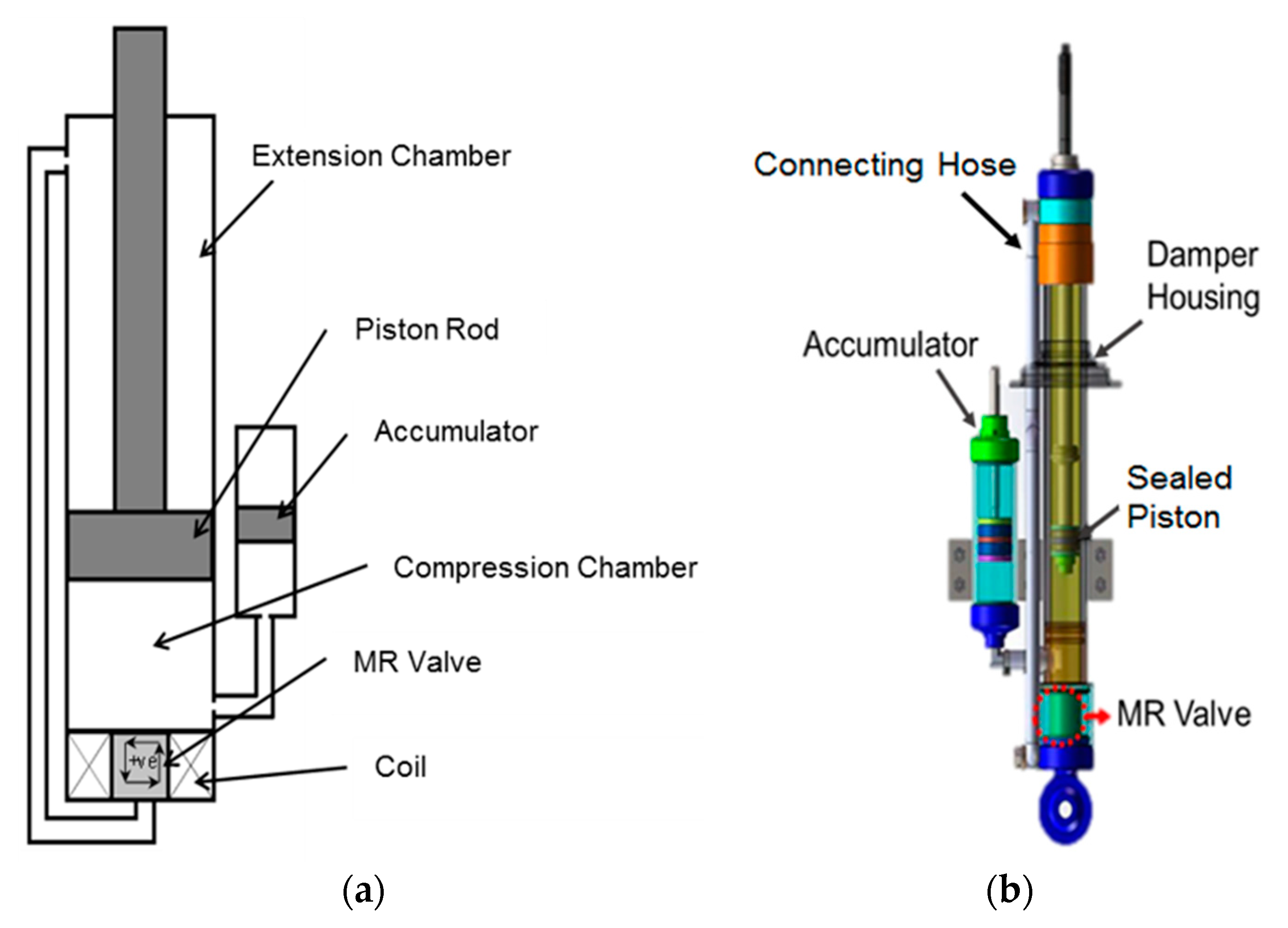
As a compromise to the pros and cons of both types, the concentric bypass design MR damper concept is proposed in this work, as illustrated in
Figure 2. The designed system consists of a rod, a piston, a cylinder, a magnetic valve, a bypass conduit and an accumulator with a floating piston. For instance, the structural arrangement looks very similar to the conventional bypass MR damper. However, there is a significant difference in the valve installation location. Unlike the conventional bypass configuration, the valve is attached to the cylinder in the same circular center axis of the cylinder. As a result, the extra span range required in the conventional bypass configuration can be reduced. The construction is also different from that of the typical structure of the internal-valve type MR damper in which the valve is attached to the piston. Although the valve placement is concentric, the valve installation is separated from the piston, thereby reducing the piston inertia and wiring complexity. The separation between the piston and the valve may reduce the risk of coil damage as there is no relative movement occurring between the coil and cylinder. Furthermore, as the piston is no longer part of the flow channel, the piston can be completely sealed, which is a severe problem to be resolved in a typical internal-valve type MR damper. With the same scenario as both the internal-valve type and the bypass type, the concentric bypass type requirement of span range is almost the same with the internal-valve type but with the benefits of having the valve unattached to the piston, like the bypass type damper.
A more detailed comparative assessment can be conducted to compare these three types with more parameters assessed, such as the volume ratio of the MR damper with MR fluid, the number of turns of the coil in the bobbin, space utilization, and the valve performance range. The assessment is based on the similar assumptions mentioned earlier that these three configurations have the same cylinder diameter of 8 cm, a valve diameter of 5 cm, an accumulator diameter of 8 cm and a stroke length of 10 cm. The results of the comparative assessment are presented in
Table 1. According to the table, the conventional piston-valve type MR damper accommodates the smallest volumetric size, while the MR damper with the internal bypass valve consumed a more substantial volumetric size and MR volume because the valve is located outside the damper housing. However, the proposed MR damper with the concentric valve requires an almost similar MR volume as the conventional piston valve. It is also assessed that the volumetric size of the concentric bypass type MR damper is close to that of the conventional piston-valve type. A salient feature of the proposed MR damper is that the field-dependent damping force is higher than those of the other types at similar magnetic field intensity. Also, the dynamic range within which the damping force is tunable or controllable using the magnetic field is larger than the conventional piston-valve type. In the later section of this work, the benefits mentioned here will be verified through simulation and experiment.
When the fluid passes through the valve, the magnetic field changes in the valve will directly influence the rheological characteristics of the fluid, which will then affect the flow of fluids and vary in the damping force. There are numerous types of magnetic-valve for MR fluid that have been developed, such as the annular valve, the radial valve, the combination of both annular and radial valve, the serpentine flux valve, and the meandering flow valves [
22,
25,
35,
36,
37]. In this work, the serpentine valve was chosen as a showcase, due to its capability to offer higher damping performance at a more efficient power consumption than its counterparts.
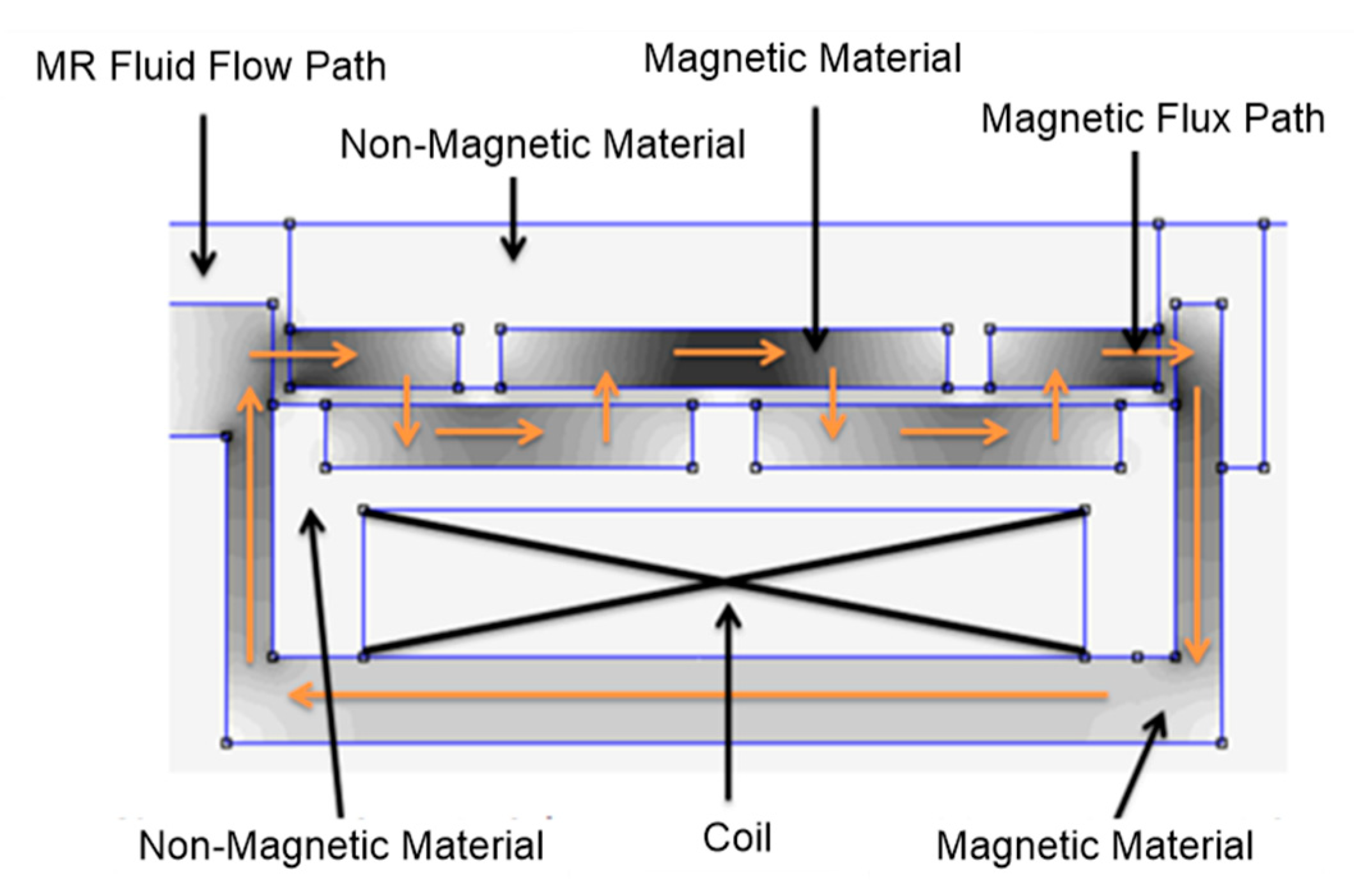
Figure 3 shows the illustration of the serpentine flux valve construction used in this study. Senkal [
38] first introduced the serpentine pattern concept in the MR brake and later applied this concept to the magnetic valve by Fatah et al. [
36]. The serpentine pattern in the flux path is formed by alternating the magnetic and non-magnetic materials inside the valve. Through the serpentine flux path arrangement, the length of the flow path can be maintained while, at the same time, the exposure of the MR fluid to the magnetic field is maximized. The use of a serpentine flux valve provides an excellent example of a condition where a valve requires a sufficient space of installation that cannot be offered by the internal-type and thus requires the use of bypass type or concentric bypass type configuration.
3. Analytical Model
The quasi-steady modeling approach of MR damper used in this work used the approach that has been widely used in previous works related to the MR damper [
36,
39,
40,
41] which embarks from the principle that the MR forces are basically derived from two forces: (i) the viscous force generated from the flow dynamics of the fluid, (ii) the field-dependent force generated from the magnetic effect. Therefore, the damping force of the MR dampers is considered to consist of the two components, the viscous and the yield, as expressed below:
where
are the damping force owing to the MR effect and damping force owing to the viscosity of the MR fluid, respectively. The pressure-drop calculation is applied to the force calculation as follows.
where ∆
and ∆
represent the viscous and field-dependent yield stresses of pressure drop, respectively, and
is the working area of the pressure in the MR damper. As the damper has only one rod, the pressure working-area is different during compression and extension. During compression, the working area is equivalent to the piston area, whereas, during extension, the working area is the residual piston area after the rod area is reduced. Thus, the equation for the area of the piston for compression is
=
. Meanwhile, the area for the rebound is
=
is the radius of the piston, and
is the radius of the rod. The difference between the compression area and extension area is the main reason why the accumulator is required. The difference between the two areas creates a volume transfer problem during the strokes of compression and extension owing to the different volume capacity, defined as
. For example, during compression, a volume
is transferred from the compression chamber to the extension chamber, whereas the extension chamber can only receive as much as
. Therefore, this implies that the remaining volume
is accumulated and transferred to an additional container outside of the two chambers, such as the accumulator.
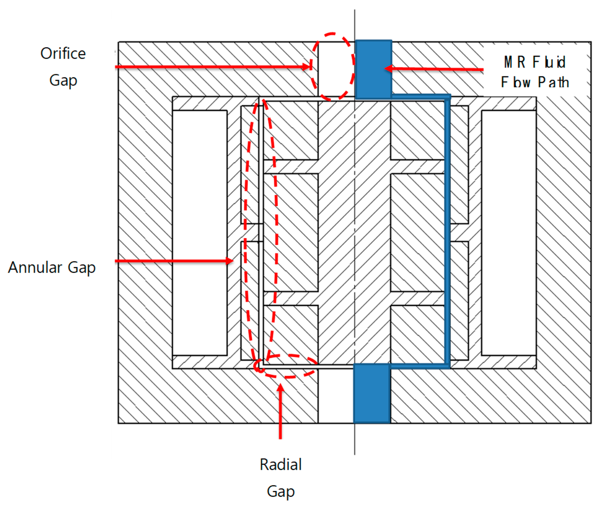
Within the damper, the valve is designed with an annular and radial construction. The orifice channel is used to attach the valve with the flow of MR fluid.
Figure 4 illustrates the construction layout of the valve showing two orifice gaps, two radial gaps, and an annular gap. As the orifice gaps on the underside of the valve are significant, the changes to the valve resulting from the reduction in pressure are not substantial, and therefore the results can be omitted for the MR valve analysis. The blue-shaded area shown in
Figure 4 indicates the MR fluid flow path in the valve. As the valve construction utilizes the annular and radial structure, all the mathematical equations must be combined to obtain the general equation of MR damper. The following equations represent the mathematical expressions of the viscous pressure drop and field-dependent pressure for the annular flow path.
where
d = valve gap,
η = fluid base viscosity,
V = velocity of piston,
A = working area of piston,
L = annular channel length of valve,
R = channel radius,
(B) = field-dependent yield stress value
c = flow velocity profile coefficient.
The coefficient of
c is obtained by calculating the ratio between the viscous pressure drop and the total pressure drop, as represented by the following equation [
42]:
The mathematical expressions for the radial gap damping force for the viscous and field-dependent yield stress are represented by [
24]
The valve gap size
d in Equations (6) and (7) refer to the radial gaps, whereas
refer to the inner radial gaps and outer radius of the radial gaps, respectively. However, for the equation of the orifice gaps, the expression is marginally different as there is no field-dependent yield stress on the MR fluid. The pressure drop equation of the orifice gaps is expressed using the viscous resistance as expressed by the following equation [
26]:
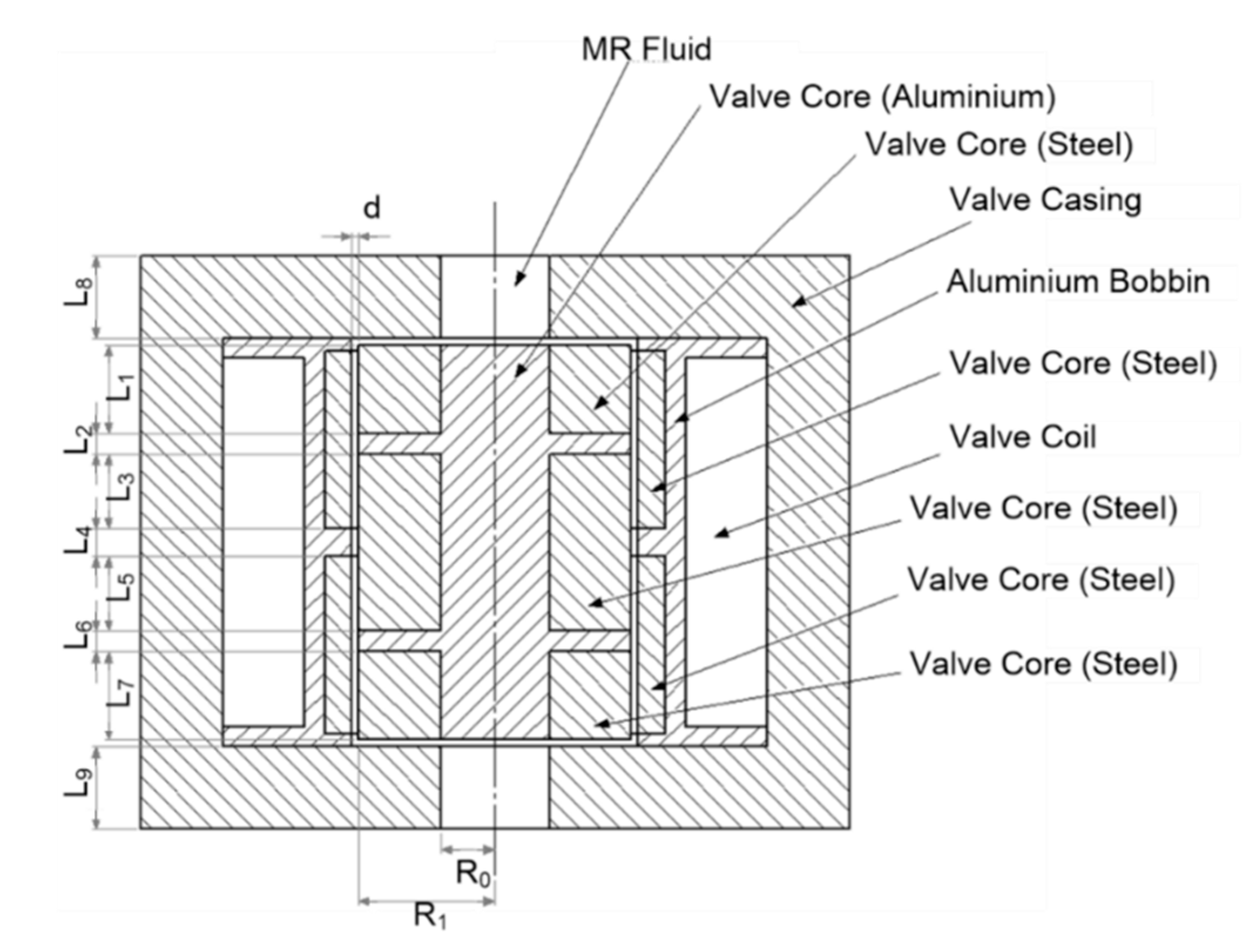
Figure 5 illustrates the structure of the valve, which consists of three components: the valve casing, valve coil, and valve core. The casing is made of AISI 1020 (steel), and the coil consists of copper wire windings and an aluminum bobbin. The valve core consists of AISI 1020 and aluminum. Meanwhile, the parameters listed in the equations and shown in
Figure 5 are presented in
Table 2. In
Figure 5, two radial gaps, two annular, and two orifice gaps are illustrated. Based on Equations (2)–(9), the quasi-steady damping force of the valve can be described by the following equation:
As
and
are equal,
=
, and
=
. Then, using the mathematical expressions, the damping forces for compression and extension are simplified as follows:
The total force of the MR damper is calculated by combining the calculated yield stress values of each zone. All the dimensional parameters presented in
Table 2 are used to derive the total damping force of the MR damper, generated from the viscous pressure drop and the field-dependent pressure drop of the MR valve.
Most of the MR damper is evaluated based on the dynamic range that the damper could produce. The dynamic range is defined as the ratio of the peak force with a maximum current input to the one with zero current input. A larger number of dynamic ranges indicates a higher value of the control range for the MR damper. The dynamic range equation is shown as follows [
42]:
4. Simulation Study
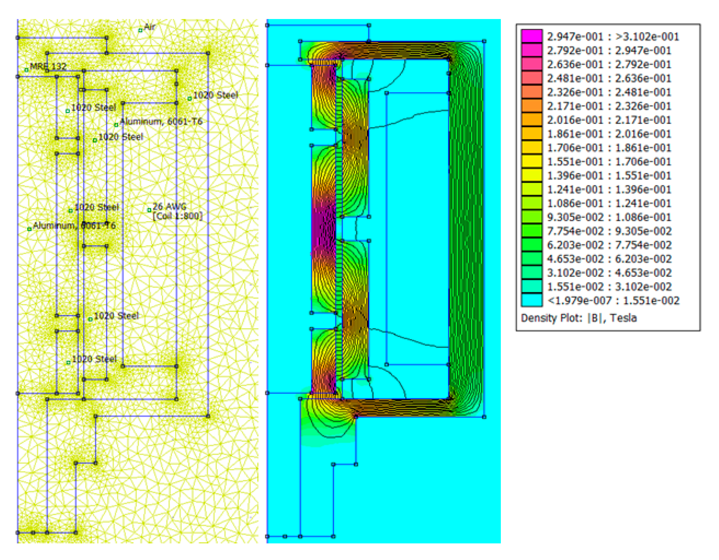
In order to design the magnetic circuit of an MR damper, the magnetic flux density is analyzed to determine the effective magnetic area. The distribution of the magnetic field strength of MR damper needs to be numerically simulated because it is challenging to measure the magnetic field strength experimentally. For predicting the MR effect on the serpentine flux with the concentric valve, numerical magnetic analysis is performed in this work by adopting commercial finite element software (FEMM software). To obtain the results, several parameters are established to conduct the simulation. The coil is designed with 800 turns of 26 AWG copper wire with a total resistance of 5.5 Ω. According to the technical specification, the maxim current that can be applied to the wire is 2.2 A, and hence, the power consumption of the MR damper will be 26.62 W. The two-dimensional axis-symmetric meshed model associated with FEMM software is used. Moreover, in this analysis, the triangular element of 16905 is generated, and the total node of 8623 is employed.
Figure 6 illustrates the meshed model and the distribution of the magnetic field intensity. The permeability of the magnetic material follows the B–H curves of AISI 1020.
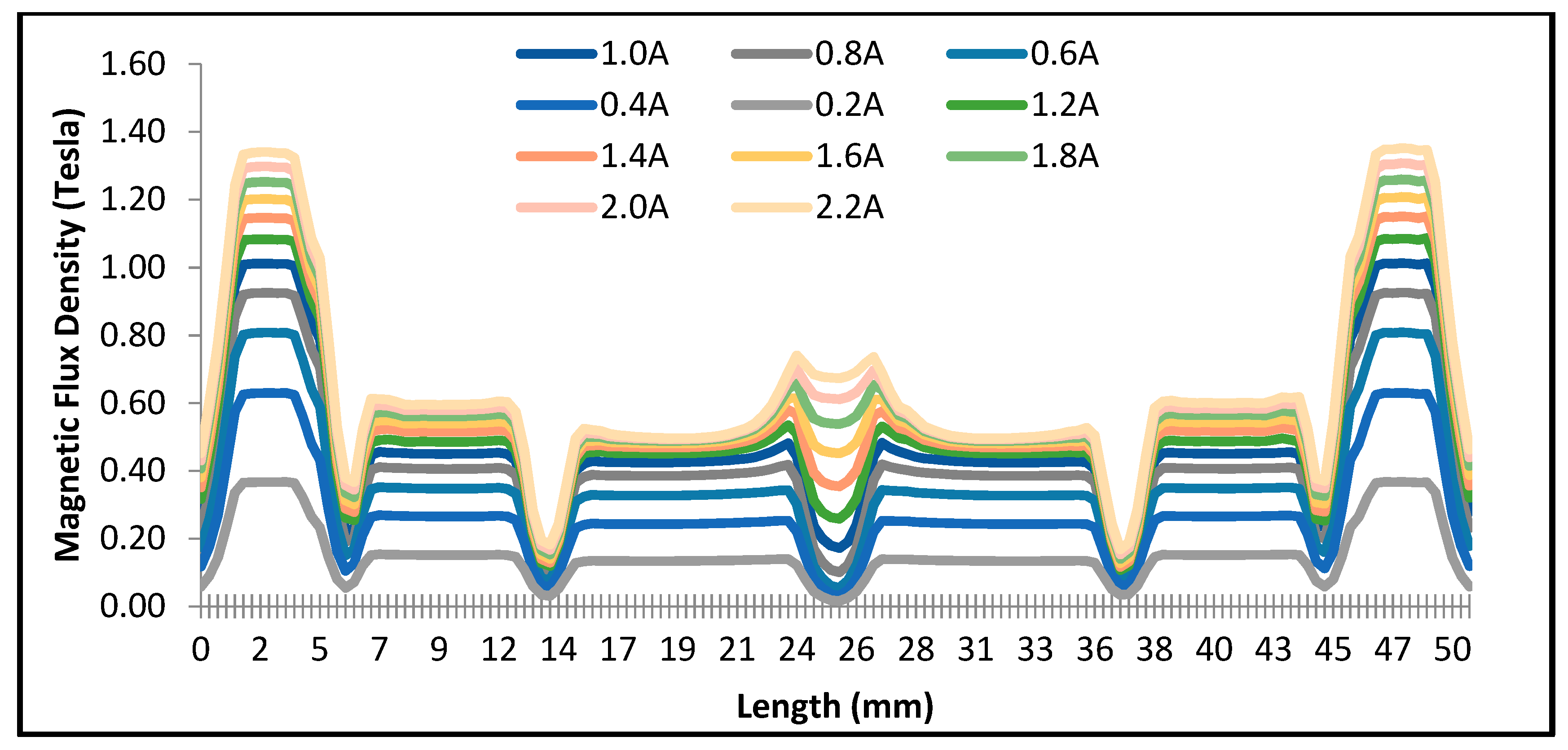
Figure 7 shows the results of the simulated magnetic flux density of the valve along the fluid flow path. It is evident that the magnetic flux density increases as the input current increases. The variation of the magnetic flux density results from the presence of the serpentine flux path in the valve as the annular zone. The highest flux density can be observed in the radial zone of the valve; it is approximately 1.3 T at a 2.2 A current input. The second-largest density occurring in the annular flow exhibits approximately 0.7 T at 2.2 A current input. Owing to the divergence of the magnetic flux density, the lowest average is obtained at the area where no magnetic flux flows along the flow path. The magnetic flux density will be used to determine the yield stress of the MR fluid. The effective area will be affected by the magnetic field strength that is generated by the current input. The MR fluid exhibits distinct characteristics of the yield stress when the magnetic field is applied to the domain of the MR fluid. In this study, the polynomial equation of MRF-132DG, from the Lord Corporation [
43], is used and represented by the following equation:
where,
is the yield stress of the MR fluid, expressed as a function of the magnetic field strength in the form of flux density B (unit: Tesla).
Given that there are variations in the magnetic flux density along the effective area, the estimated yield stress in each zone will vary. Therefore, the calculation for predicting the pressure drop is conducted with a different region.
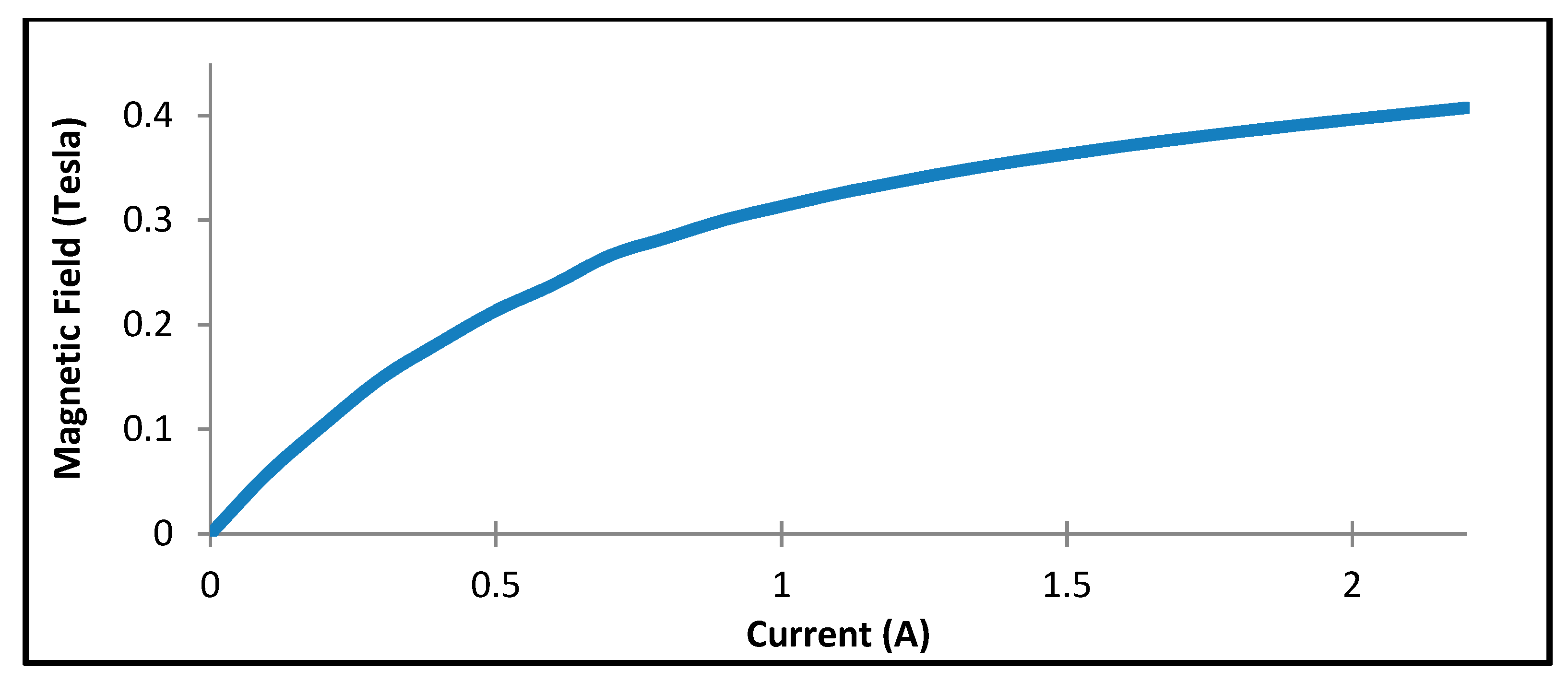
Figure 8 illustrates the curve conversion of the valve, wherein the correlation between the applied current and magnetic field generated along with the valve considering the average of the total magnetic flux density is illustrated. The graph shows the increasing trend when the input current applied to the valve increases. From the graph in
Figure 8, the polynomial equation for the yield shear stress of the new MR damper can be expressed as follows:
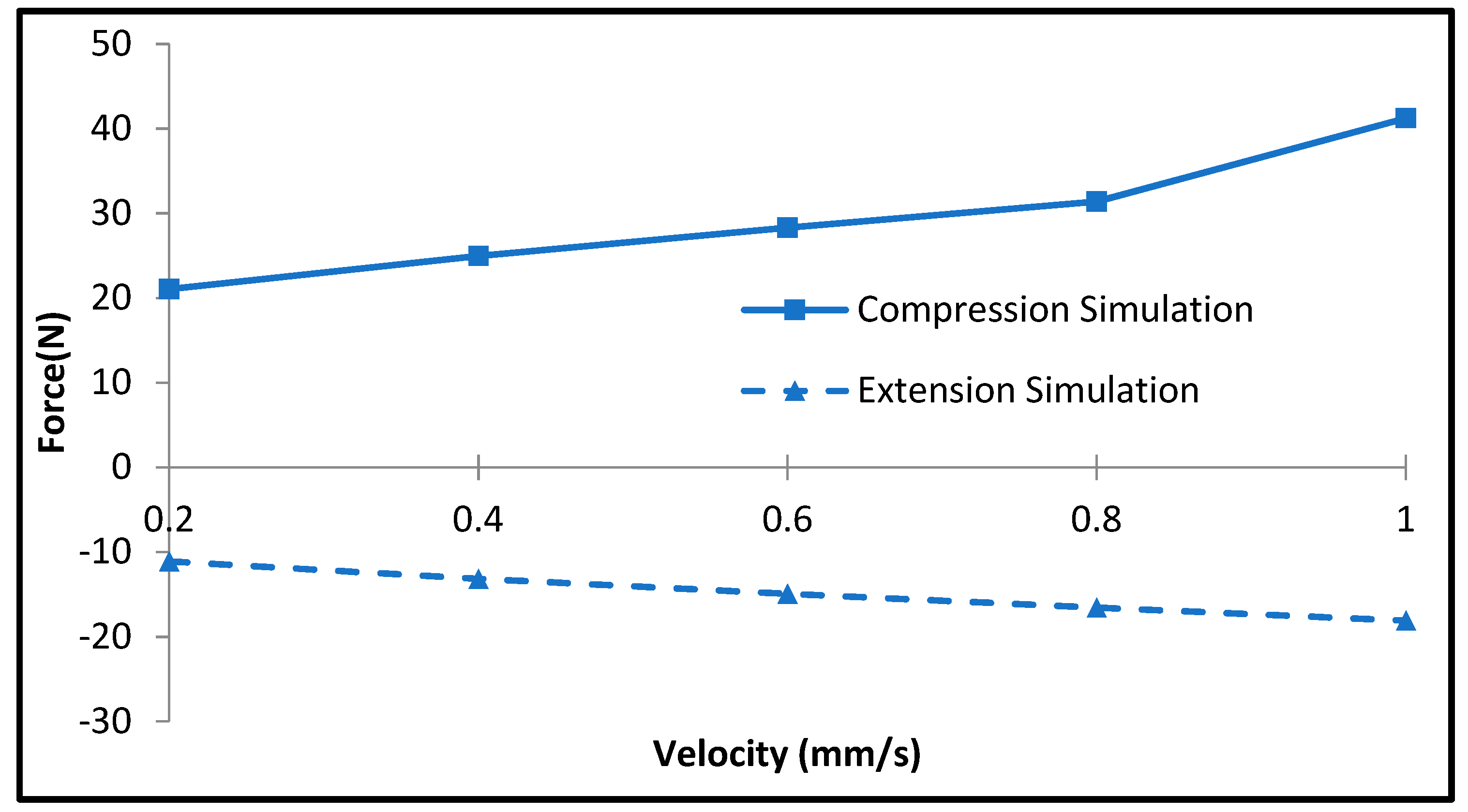
Figure 9 shows the variation in the simulated damping force with that of the piston velocity in the off-state condition (without input current). The simulation results are obtained using Equations (11)–(14). It is identified from this figure that the damping force of the MR damper at off-state condition is approximately 41 N for the compression side with the velocity 1 mm/s, whereas it is approximately 18 N for the extension side. It is evident that the damping force increases as the piston velocity increases, as expected from Equation (10).
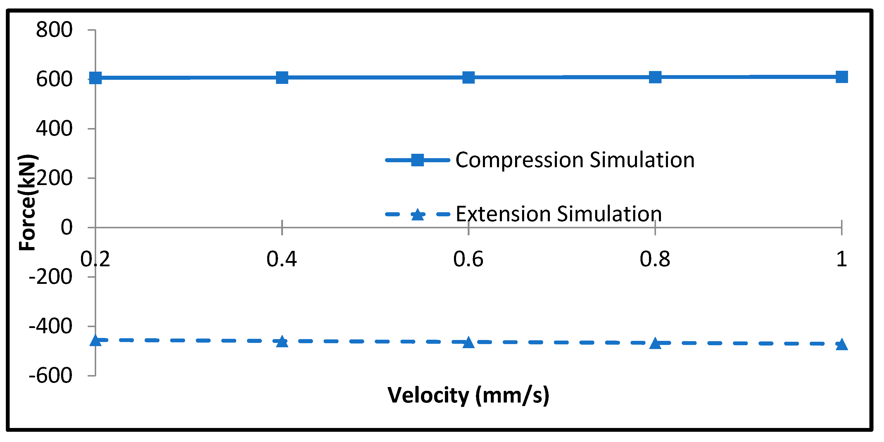
Figure 10 presents the simulated damping force in the on-state condition with an input current of 0.3 A. It is observed that the effect of the piston velocity is highly marginal, and hence, the damping force is almost constant regardless of the piston velocity. Thus, the damping force owing to the input current is dominant. It is observed from the figure that the damping force of the MR damper with 0.3 A is approximately 610 N for the compression side with a velocity of 1 mm/s, whereas it is approximately 470 N for the extension side. It is noted here that lower current input is chosen for the comparison due to the discrepancy in the data that later will be shown during the experiments.
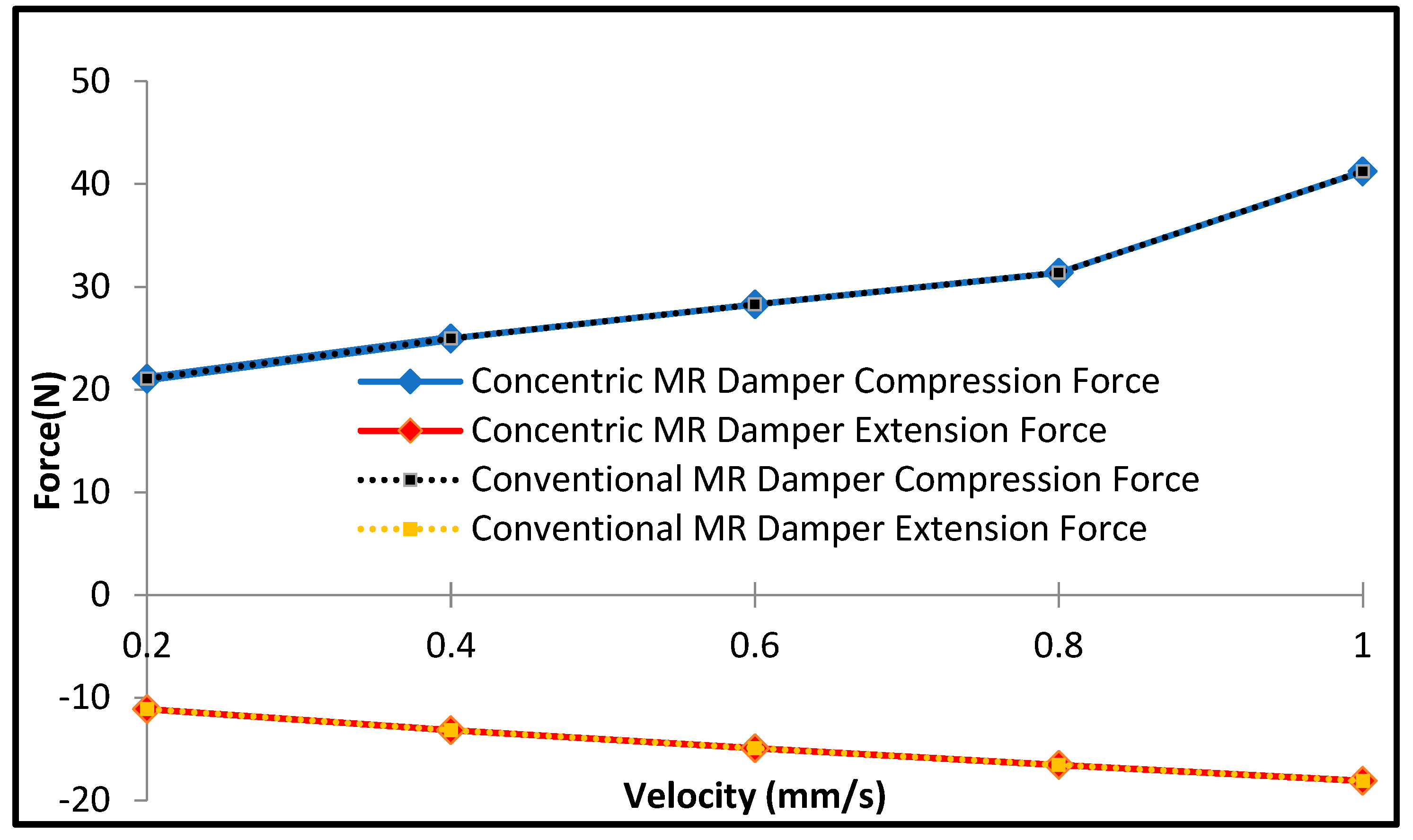
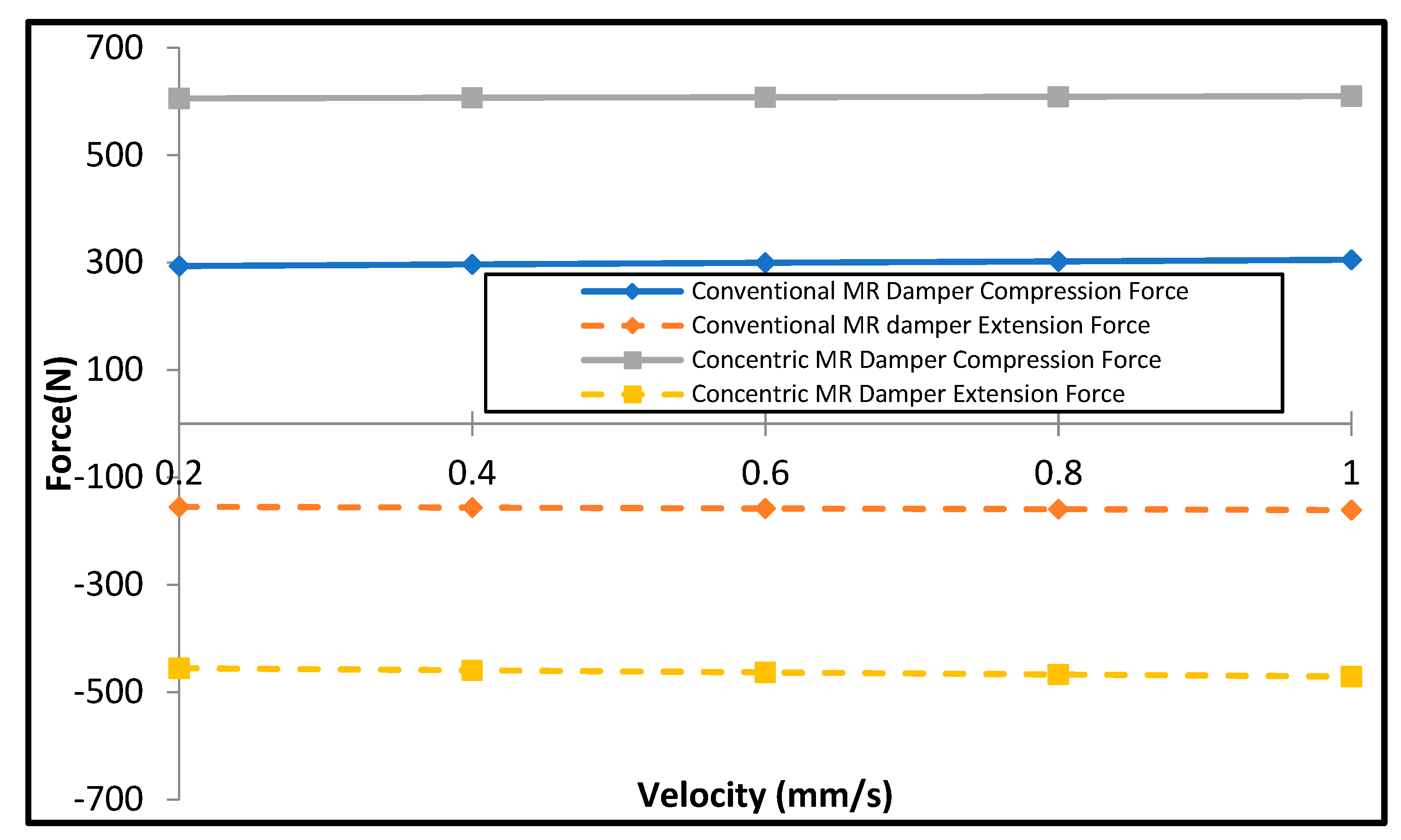
Figure 11 and
Figure 12 show the off-state simulation damping force and the on-state simulation for the conventional MR damper and concentric MR damper, respectively. As is evident from
Figure 11, the off-state results for the concentric MR damper and conventional MR damper are similar, as identical valve sizes are used for the two dampers, and the friction and accumulator forces are omitted in the model. However, for the on-state (0.3 A) simulation, the concentric MR damper produces a higher damping force than that of the conventional MR damper for both the compression and extension sides, as shown in
Figure 12. This is because the concentric valve structure has a more significant number of coils turns than the conventional one under similar space constraints, as discussed in the previous section. It is noted here that in this simulation, the accumulator is set to have a pressure of 7 bars, which is similar to that for the measurement. The result shown in
Figure 12 directly indicates the higher dynamic range of controllable damping force of the proposed MR damper compared with the conventional MR damper of compact size. This will be a significant benefit in the actual applications of MR damper. It is noted here that in this comparative work, the MR damper with the piston bypass valve is not considered since it has a bulk structure, a much larger volume size than the two types compared here.
5. Experimental Study
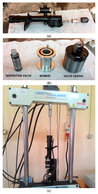
The validity of the analytical model was verified using the measurement of the fabricated prototype shown in
Figure 13. The valve was fabricated with dimensions similar to those discussed in the previous section, and the fluid domain was filled with MRF-132DG supplied from Lord Corporation [
43].
Figure 13a presents the breakdown of the MR damper, and
Figure 13b shows the components breakdown of the valve system. The performance test was conducted by installing the MR damper in the dynamic test machine (Shimadzu EHF-L series) as shown in
Figure 13c. The available measurement data from the machine are the rod displacement and the reaction force from the damper that is transferred to the host computer. Later, the logged data were then capable to be saved and analyzed outside the host computer.
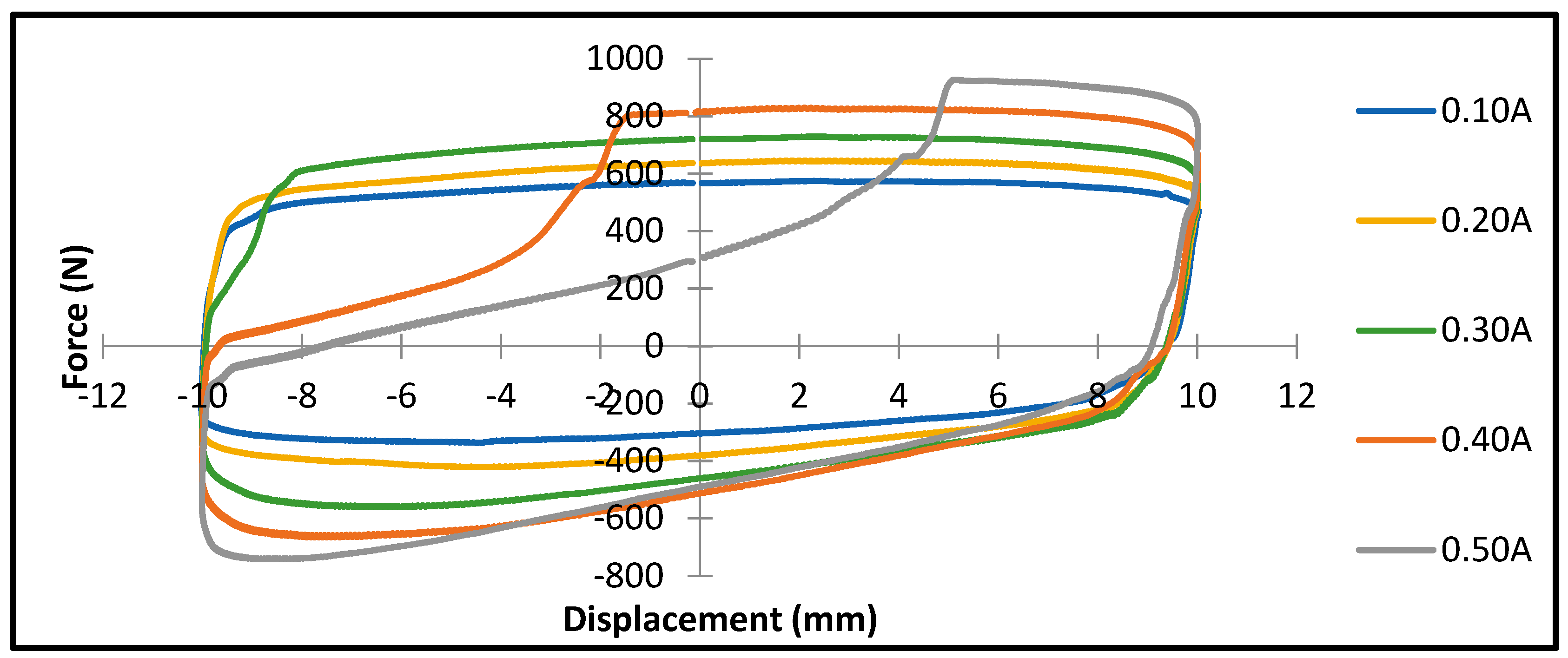
The dynamic test machine was programmed to create oscillatory movements in the form of a sinusoidal wave that resulted in pressure variations inside chambers of the MR damper. The changes in the pressure at the lower and upper peaks of the MR damper showed the flow changes at the throttling valve and were measured in real-time by the dynamic test machine. The sine waveform was intentionally selected to represent the actuating movement of the dynamic test machine to record the peak force of the upper and lower sides. The experiment was conducted using the current inputs 0.05, 0.10, 0.15, 0.20, 0.25, and 0.3A, correlating to peak velocities of 1, 2, 4, 5, and 6 mm/s, respectively. The higher current input up to 0.5 A was also conducted for the experiments and the velocity was fixed at a lower speed, specifically 6 mm/s, to see the behavior of the MR damper in the higher current. The velocity and associated damping force with constant frequency were plotted to observe the trend of the relationship between the input current and maximum damping force.
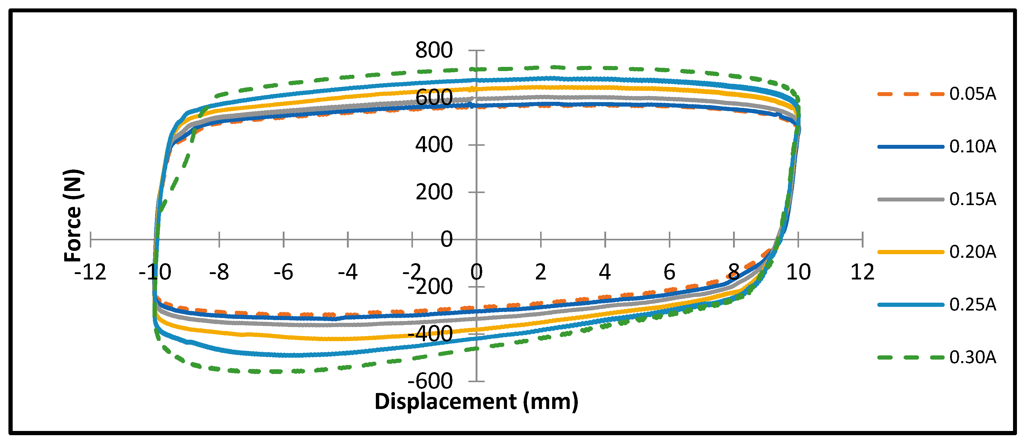
Figure 14 and
Figure 15 show the damping force at different currents, measured under the condition of the excitation magnitude of 10 mm and the excitation frequency of 0.1 Hz with a sinusoidal loading. It is noted here that the excitation frequency is limited owing to the testing machine capacity with a 10 mm excitation amplitude. Meanwhile, selecting lower amplitude is not preferred at the moment as the noise appeared more significantly and projected characteristics are not in the interest of this current study. It is identified from this result that the maximum damping force can reach up to 750 N for the compression side and up to 600 N for the rebound side, with 0.3 A. It is also observed from the force versus displacement (F–D) plot that the damping force is not symmetrical with respect to the zero displacements as the friction owing to the seal is not equal in the upward and downward directions. Moreover, as the accumulator integrated with the MR valve is activated by air pressure, the induced floating force to balance the position of the piston is different in the upward and downward directions. However, this issue is not crucial to control the field-dependent damping force, as the feedback controller associated with the MR damper can overcome the unsymmetrical property, parameter variation, and external disturbance to achieve the desired motion or successful vibration control [
44,
45].
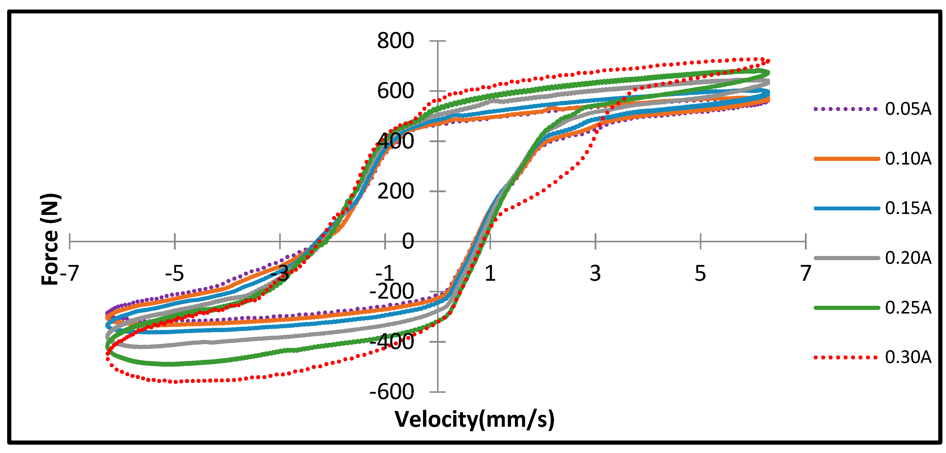
Figure 16 presents the plot of the damping force versus the piston velocity at various input currents. The velocity is set to 6 mm/s with a sinusoidal loading and with various currents applied with an increment of 0.05 to 0.30 A. The maximum damping force reaches up to 750 N for the positive velocity side and up to 600 N for the negative velocity side when the current input applied is 0.30 A. In the positive velocity side, the damping force reaches up to 550 N at 0.05 A, whereas it reaches up to 250 N in the negative velocity side.
6. Discussion
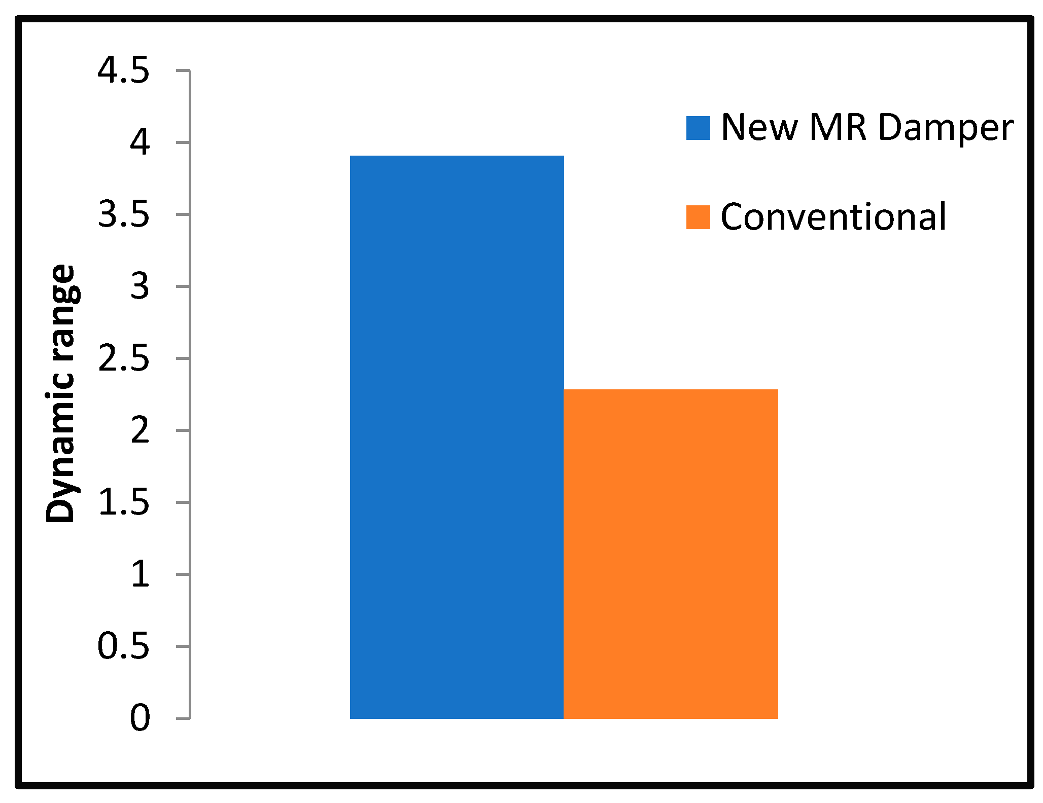
Figure 17 shows the dynamic range of the new MR damper and the conventional damper based on the calculation at the simulation stage. The dynamic range is one of the essential aspects of evaluating the performance of the new design of MR damper. The more considerable value of the dynamic range is expected to provide a more extensive control range of the MR damper. Based on Equation 13, the dynamic range of the new MR damper can be evaluated and compared with the conventional MR damper. Based on the calculation results illustrated by
Figure 17, the new MR damper design is capable of demonstrating a higher dynamic range, around 1.5 times higher than that of the conventional MR damper when excited with the same current of 0.5 A. These results are based on the assumption that only the viscous forces and the field-dependent forces are working in the damper. However, it is clear that there are discrepancies between the simulation and the experimental results and thus, it should be noted that the full potential of the new concentric bypass design, such as the dynamic range capability, can only be achieved when the problems in the prototype can be resolved.
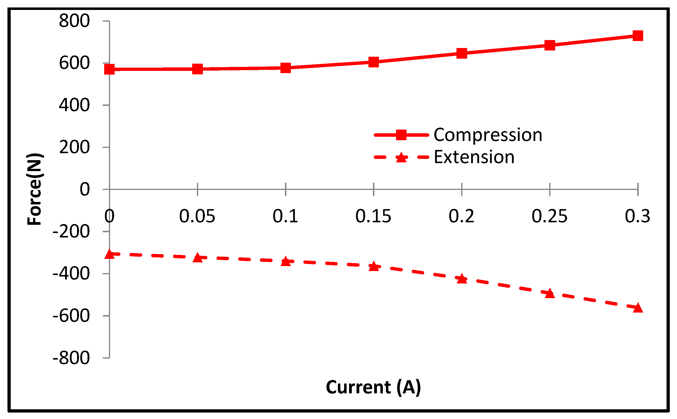
Figure 18 shows the relationship between the current input and the maximum damping force generated under the fixed velocity of 1 mm/s. It is observed that the damping force gradually increases as the input current increases. The increment speed of the damping force with respect to the input current is not high, unlike many results of the field-dependent damping force [
44,
45]. This is owing to the low level of the applied current. In general, the damping force sharply increases as an input current over 1 A is applied to the MR fluid domain [
44]. As remarked at the end of the conclusion, the study on the damping force controllability, which is directly related to the response time of the damping force to the input current, will be undertaken as future work.
In order to validate the effectiveness of the analytical model of the proposed MR damper described in this section, a comparison between simulation and experiment at various input currents is undertaken.
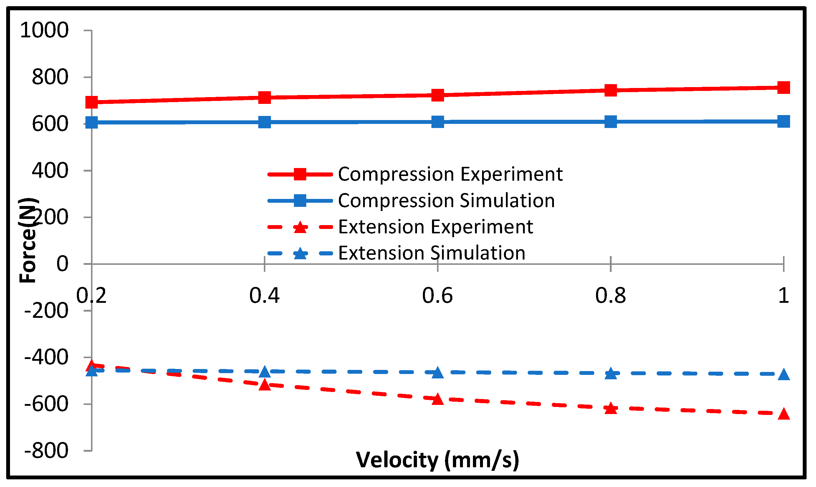
Figure 19 shows the damping force at 0.3 A obtained from the simulation and measurement. The agreement between the two approaches is acceptable within the piston velocity range considered in this work. However, it is observed that the error increases as the piston velocity increases. It is also observed from the experimental result that with the increment of the current input, the slope of the damping force increases for both the compression and extension sides. This is owing to the effect of the friction force from the seal and accumulator force on the damping force. As discussed in the previous section, both the friction force and accumulator force are not considered in the analytical model. The model is derived with the assumption that the friction force from the seal as well as the accumulator force, can be neglected. However, as measured, in the prototype used in this study, the seal friction and the accumulator forces cannot be ignored. The prototype is prepared to handle a higher fluid pressure rating than the typical design. Therefore, the seal tolerances were made tighter and thus have more friction effect. The friction adds a damping force effect and is also known to be variable to the speed of wall contact, as observed in
Figure 19. The friction effect also affects the measured off-state force, where the values are ten times more significant than the simulated off-state damping force.
The primary goal of the experiment is to evaluate the damping characterization of the new concentric MR damper. The measured performance of MR damper is only up to 0.1 Hz in this study to avoid any degradation of the piston seal due to problems in the accumulator. The excitation frequency limitation is also the main reason why the effective maximum current input in the MR damper only reached up to 0.30 A. Ideally, the accumulator should have a much higher force to move the floating piston than the damping force produced by the throttling valve. However, in this experiment, the accumulator force was only around 750 N, which was only exceeded when the applied current input was higher than 0.30 A. In this experimental work, the accumulator is set to have a pressure of 7 bars, which is lower than that of the typical MR damper [
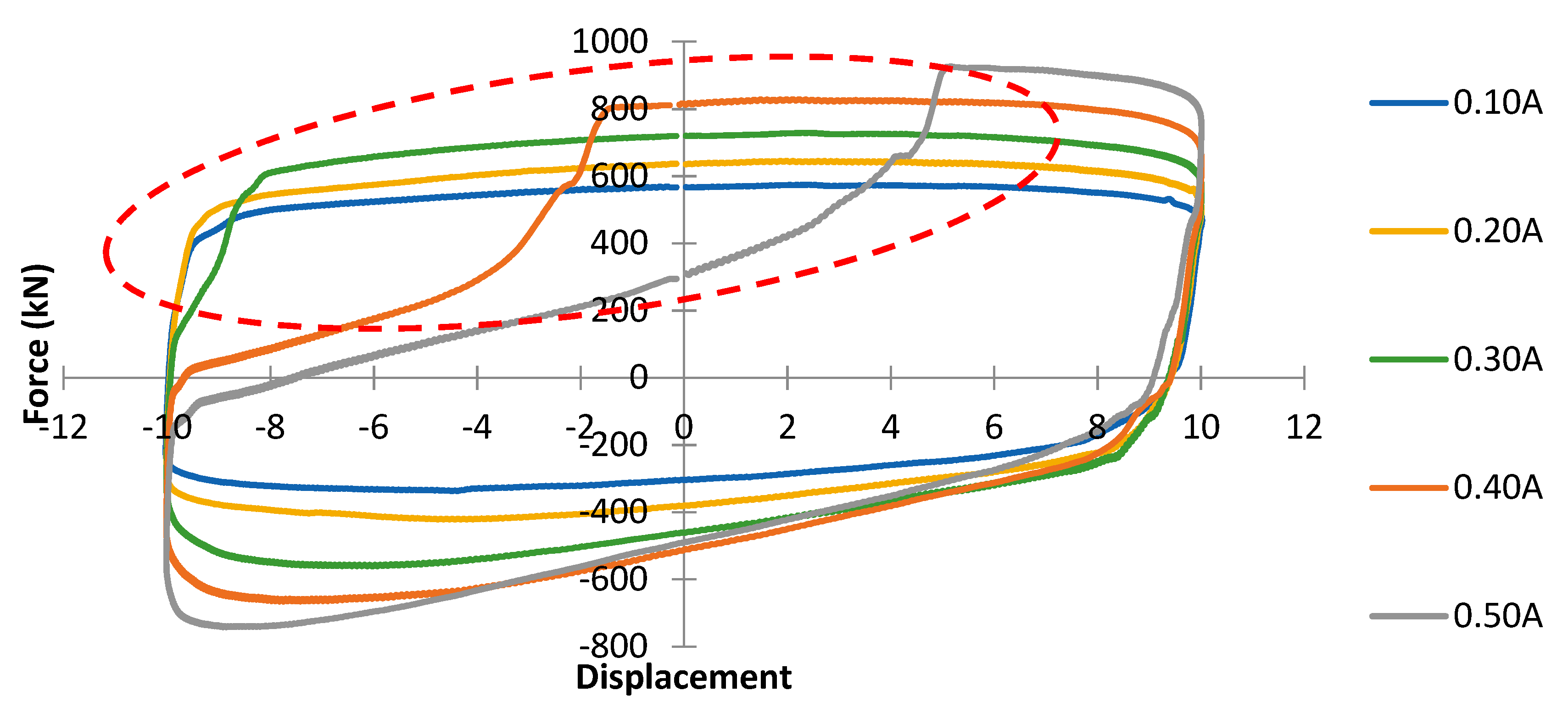
44]. When this occurred, the blocking force generated by the throttling valve will be higher than the force of the accumulator and temporarily creates a more apparent elastic effect as the force–displacement curve will have a more visible slope. This phenomenon occurs during the measurement, as shown in
Figure 20, when the damper experiences compression and the valve excitation current is 0.3 A and above. As the excitation current increases, the valve pressure drop increases as well and the blockage force from the valve might be higher than the elastic force from the accumulator. In this situation, the fluid will be forced to flow in two stages. The first one is when the fluid is forced to the accumulator until the accumulator reaches full capacity, which is reflected in a steeper slope in the force–displacement curve. The second stage is after the accumulator reaches full capacity; the remaining fluid will be compressed to a higher pressure and surpass the blockage force from the valve to flow to the other chamber. These situations also create a void-like effect during extension that deteriorates the damping characteristics, as shown in
Figure 20 (dashed line circle). This phenomenon is not preferred in a damper, as the ideal damper should predominantly act as a damping element without a spring effect. As a solution, the amount of volume compensation by the damper should be minimized, whether by reducing the diameter of the rod or utilizing a double rod configuration.
The results also show that the off-state damping force is higher compared to the prediction. Several reasons can be the cause of the higher off-state damping force, including the gap size and the orifice channel of the valve. Referring to the equation of calculating force for the MR damper, the gap size is inverse-cubically related to the value of the force generated by the MR damper. In other words, the marginal gap value significantly changes with the generated force of the MR damper. In this case, the required gap size is 0.75 mm; the possibility of the actual gap being inaccurate or incorrect is high. This means that the actual off-state damping force can also be incorrect with the prediction. An orifice channel is installed on the damper, which may help to fix the value and provide significant value to the generated damping force. Although the data calculated from the simulation are different from the experimental value, this replicates the ideal condition to avoid any errors in the damper. Furthermore, as the velocity increased, the damping force pattern did not increase accordingly in the experimental data, which may be due to the friction and accumulator factors that are not included in the calculation of the viscous force and yield force of MR damper. Additionally, the error may also result from air bubbles present in the MR damper during the filling process.
Conversely, the trend of the on-state damping force versus the velocity in the simulation and experiment shows fewer discrepancies (refer to
Figure 19). From the experimental results, with the increment of the current input, the slope of the force thereby increases for both the compression and extension with the effect shown in the extension force. The slight difference is due to the friction force and accumulator force, and therefore, the experimental data and simulation data agree well. For the future improvement of this new MR damper design, several improvements can be added to further enhance the performance of MR dampers, such as the accumulator and the orifice channel. A new accumulator with a higher force could be located in the MR damper to improve the damping force. However, the accumulator must have a force higher than the valve to counteract the force generated in the valve. The orifice channel could be changed or eliminated to evaluate the possibilities that could affect any force generated by MR damper.
7. Conclusions
In this work, a new MR damper featuring the concentric valve structure was designed, fabricated, and tested at a low piston velocity to demonstrate certain advantages such as the high dynamic range of controllable damping force with compact size. After discussing three configurations of valve structure in MR dampers, design assessment in terms of the size volume of MR damper, the volume of MR fluid, and the number of coil turns was conducted. It has been determined from this assessment that the proposed MR damper with the concentric valve structure exhibits the highest dynamic range with the compact size. This was verified from the analytical model in which the frictional force and accumulator force were omitted to focus on the field-dependent damping force variation. In order to verify the benefits of the proposed design concept, a prototype of the proposed MR damper was fabricated and tested. It was demonstrated that the damping force at constant piston velocities can be increased up to 480 N at 0.3 A. In addition, it was validated that the damping forces predicted by the proposed analytical model at different piston velocities are consistent with those of the measured results corresponding to these velocities.
The results presented in this work verify that the concentric valve structure of MR damper can provide an enhanced dynamic range of controllable damping force with certain advantages such as compact size, convenient assembly, straightforward maintenance, and the small volume of MR fluid. These advantages are directly related to the cost of the MR damper, which is a critical factor for the successful commercialization of MR damper. It is finally remarked that damping force characterization at higher piston velocities and various excitation frequencies will be undertaken and compared with commercial or conventional MR damper as a second phase of this work. Furthermore, damping force control of the proposed MR damper using an appropriate controller will be performed to demonstrate the advantage of the more extensive dynamic range.
