Review on the Development, Control Method and Application Prospect of Brake-by-Wire Actuator

Abstract
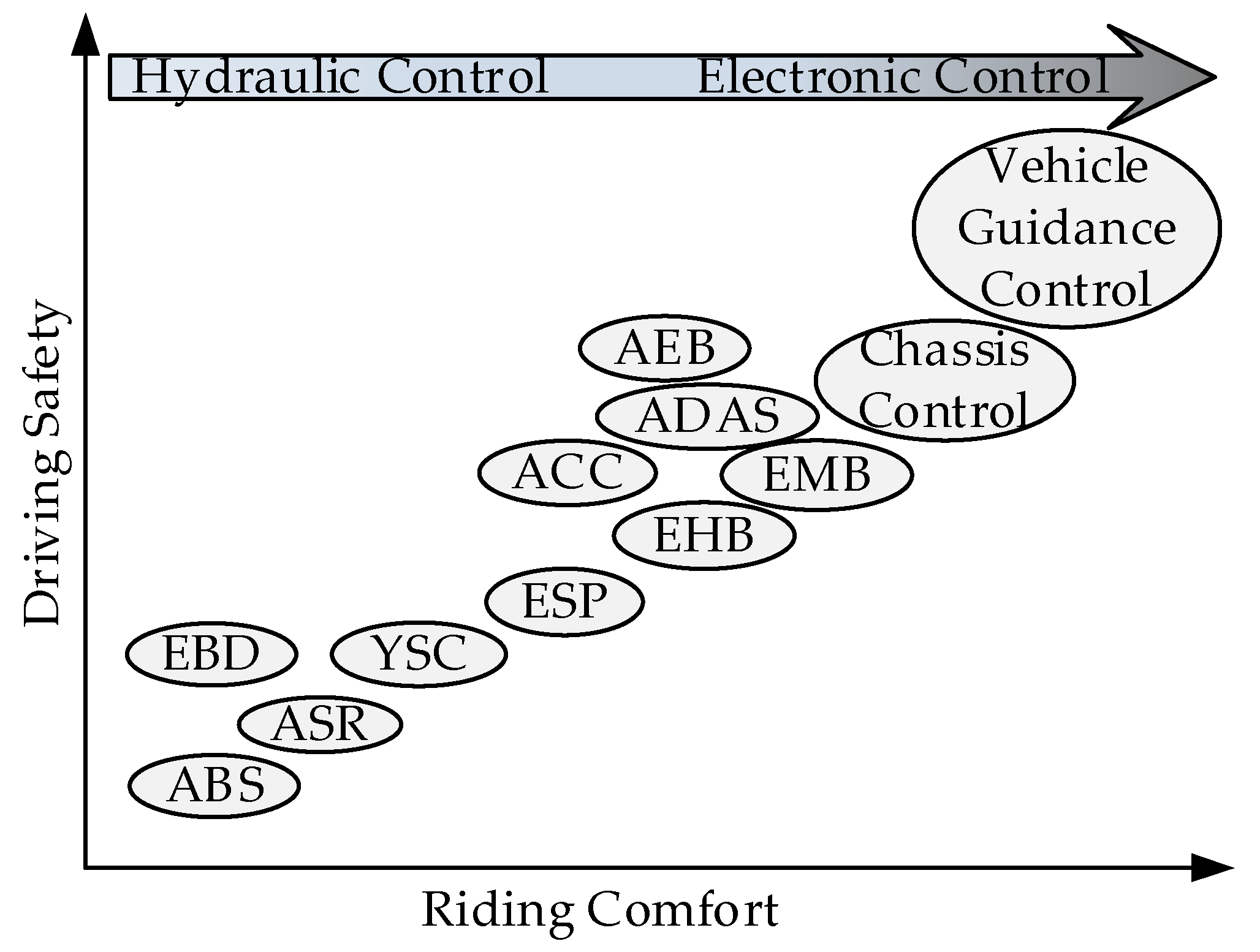
:1. Introduction
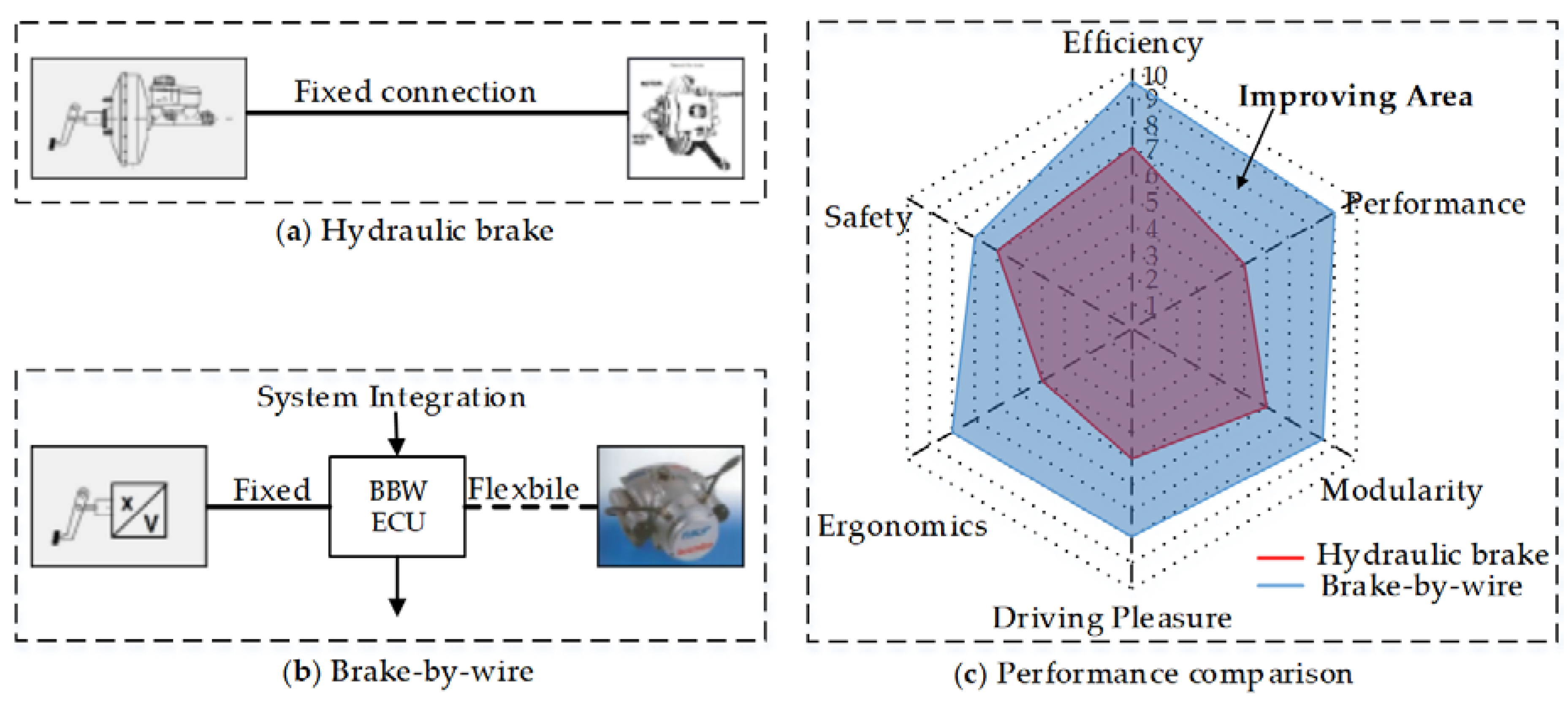
2. Classification and Key Technologies of BBW
2.1. Classification and Structure of Brake by Wire Actuator
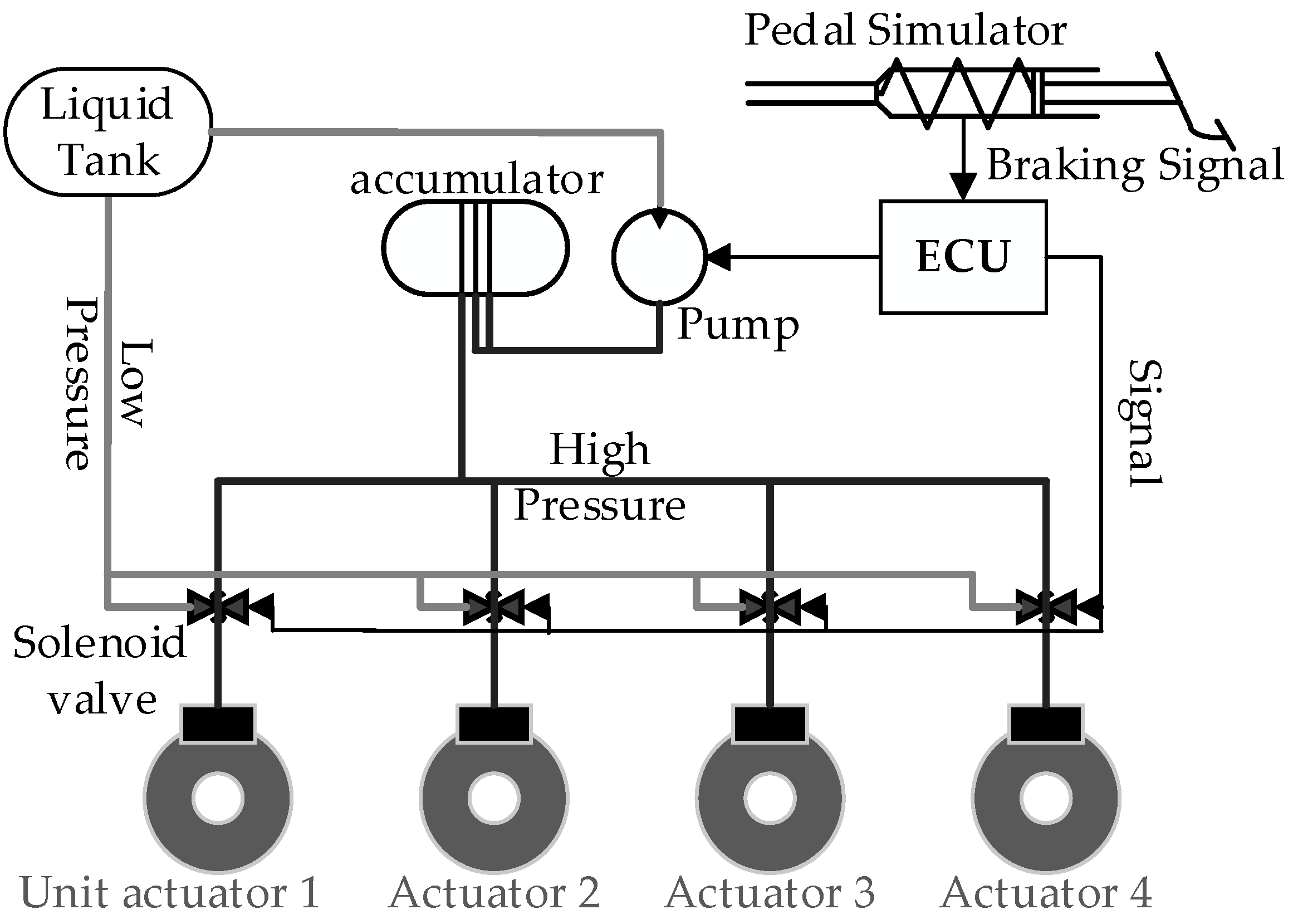
2.1.1. Electro-Hydraulic Brake
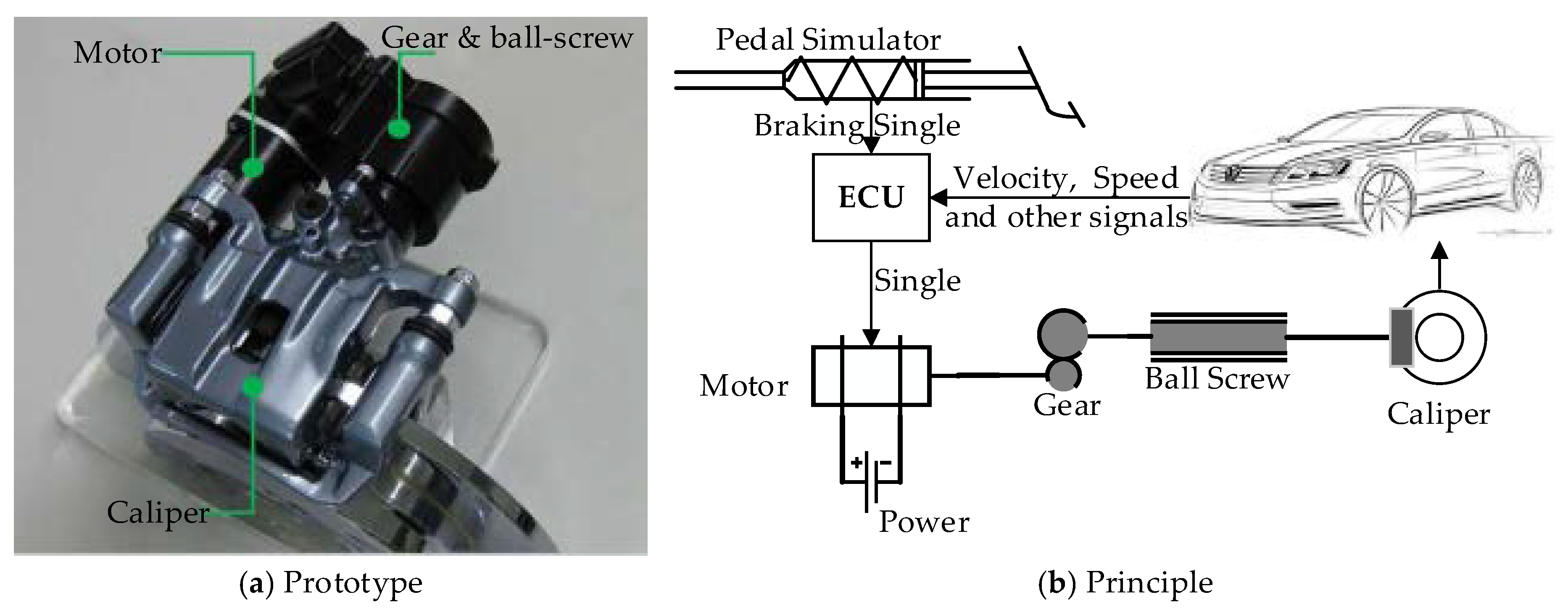
2.1.2. Electro-Mechanical Brake
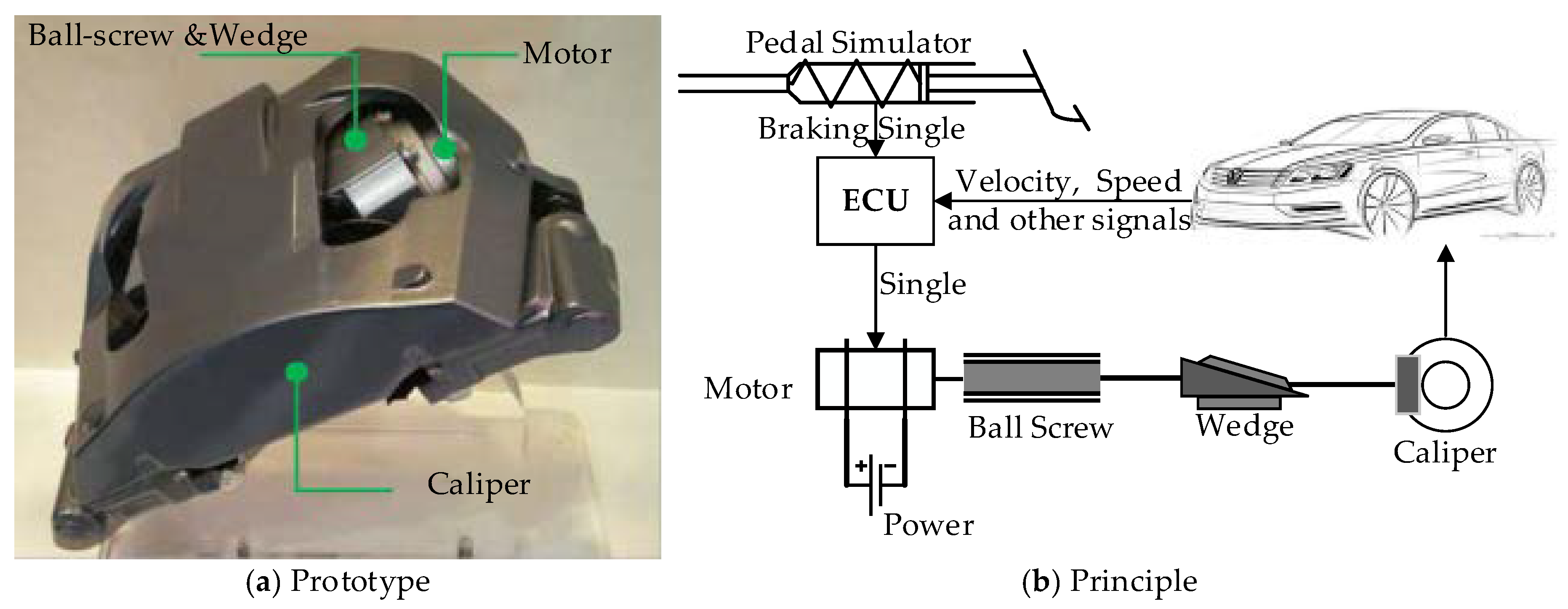
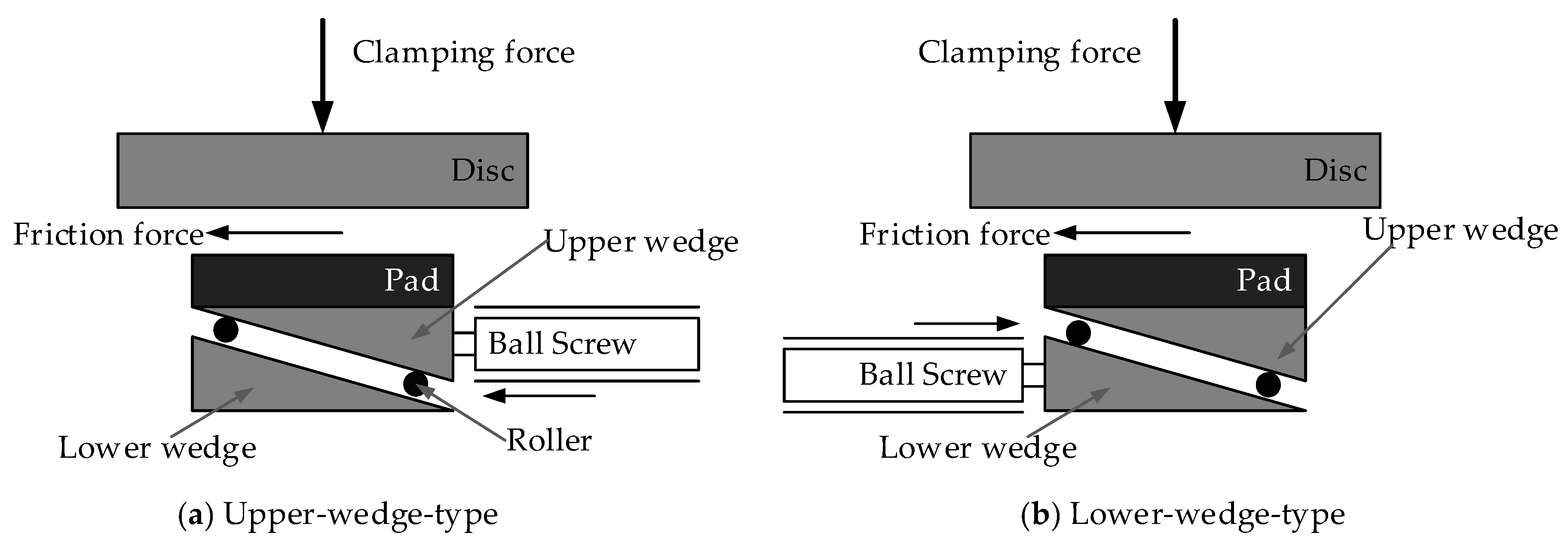
2.1.3. Electro-Wedge Brake
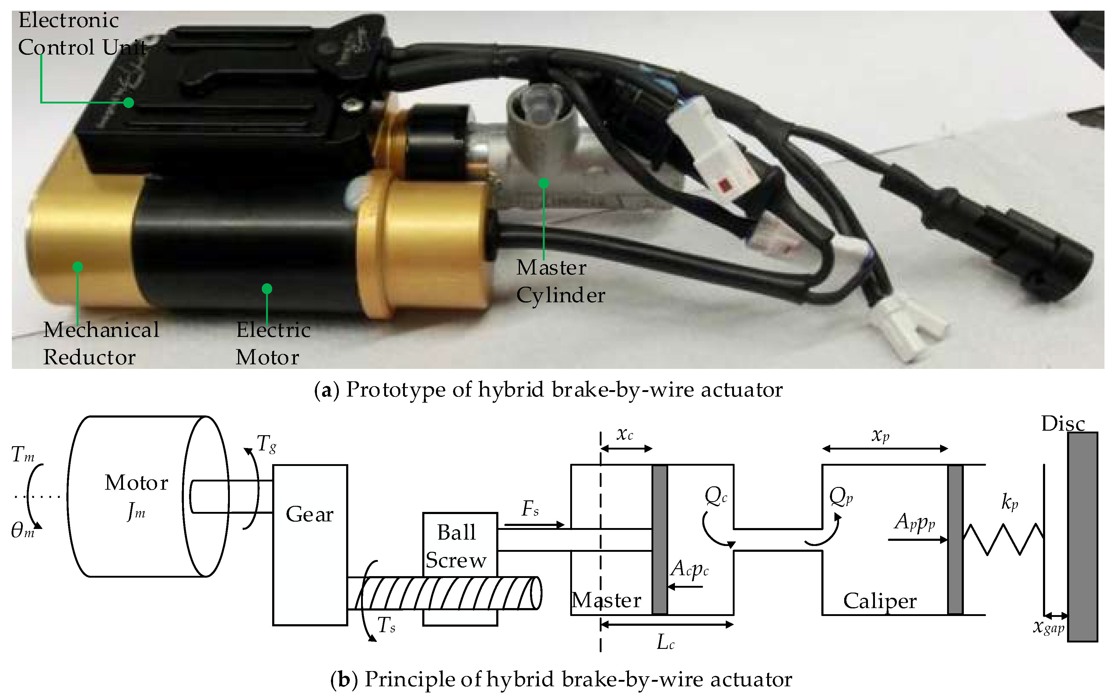
2.1.4. Hybrid Brake-by-Wire Actuator
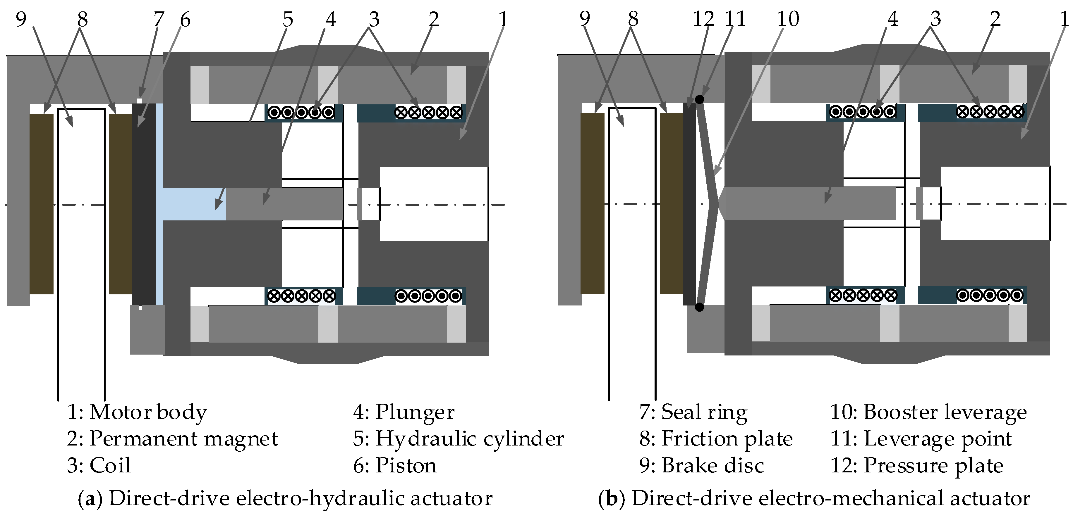
2.1.5. Direct-Drive Electro-Hydraulic/ Electro-Mechanical Actuator
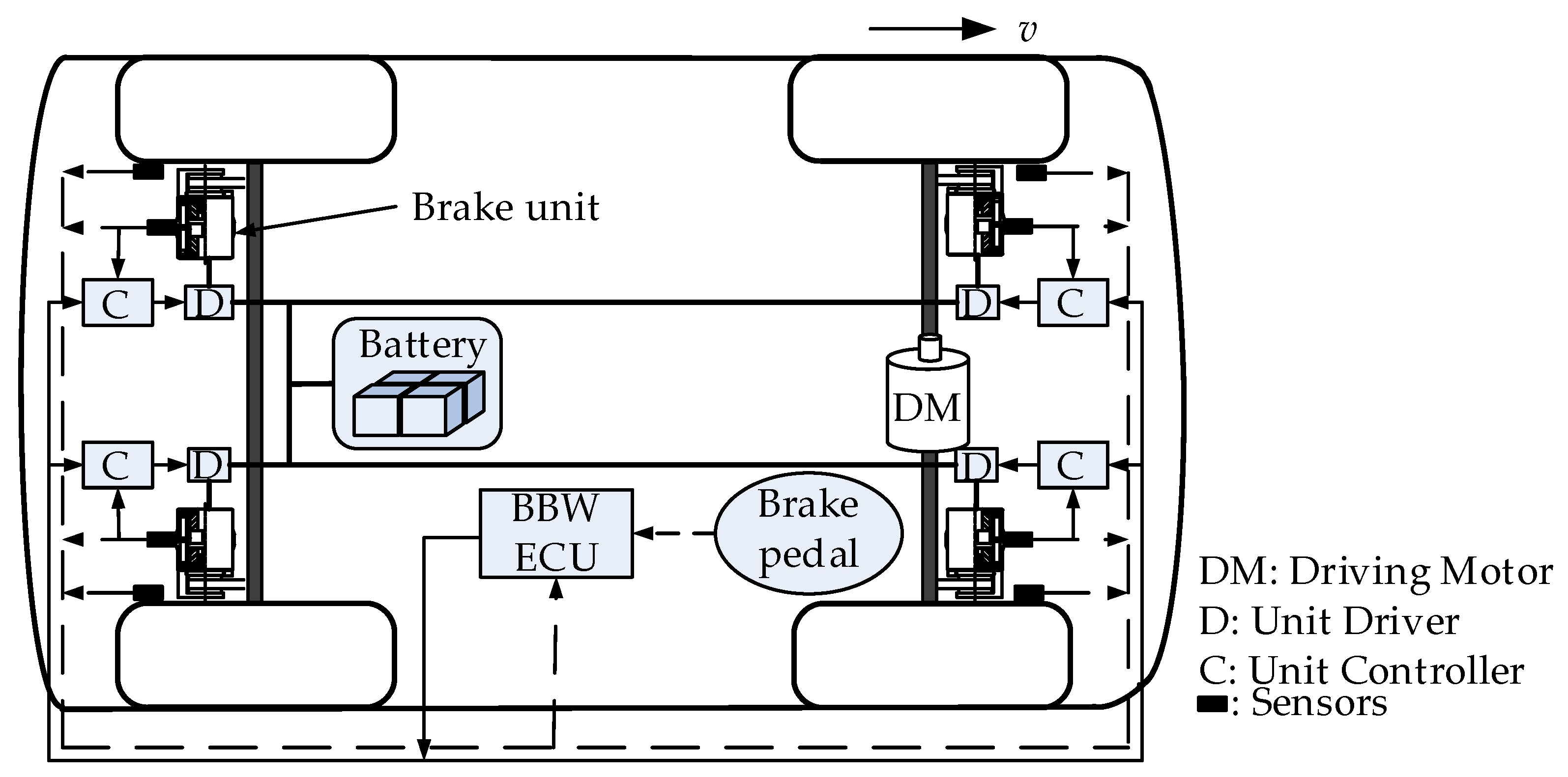
2.2. The Composition of Brake-by-Wire System
- Four wheel actuators, such as EMB or EWB, described above.
- Electronic pedal simulator and various sensors for converting the driver’s braking action, velocity, wheel speeds, and other signals into electrical signals.
- Energy management system for providing sufficient and stable electrical energy for actuator and control system.
- Communication network for transmitting various electrical signals. Presently, the main communication network is usually CAN bus, and the auxiliary network is FlexRay bus.
- Central ECU and actuator controller. ECU comprehensively calculates and processes all signals, and sends the brake force signal to actuator controller. The actuator controller regulates the actual braking force according to ECU signal and other necessary signals.
2.3. Key Technologies of BBW
3. Control Technology of BBW
3.1. Parameter Estimation
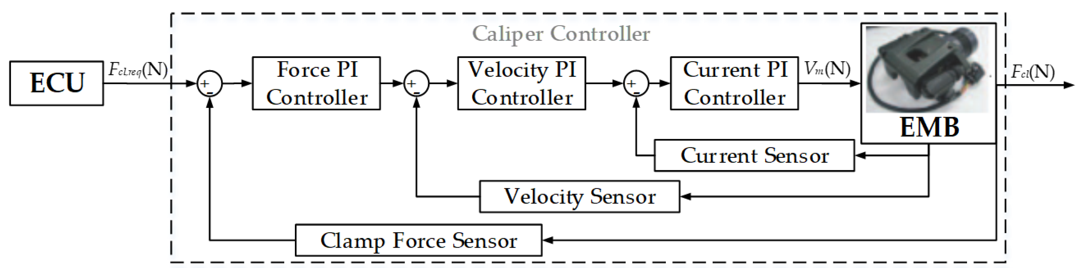
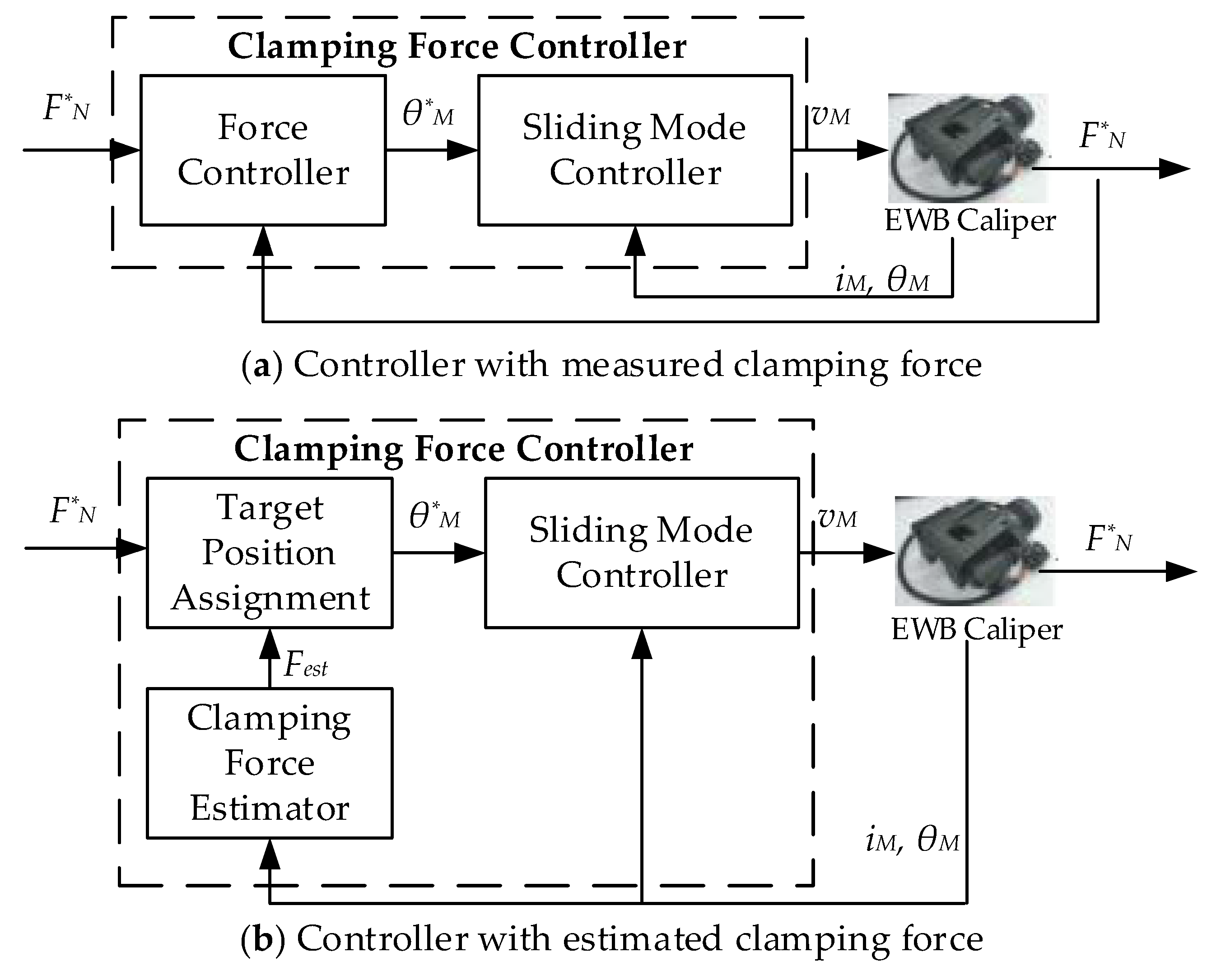
3.1.1. Caliper Force/Braking Force Estimation
3.1.2. Estimation and Compensation of Friction Force
3.1.3. Estimation and Adjustment of Brake Gap
3.2. Control Method of Braking Force
3.2.1. Cascade Control
3.2.2. Sliding Mode Control
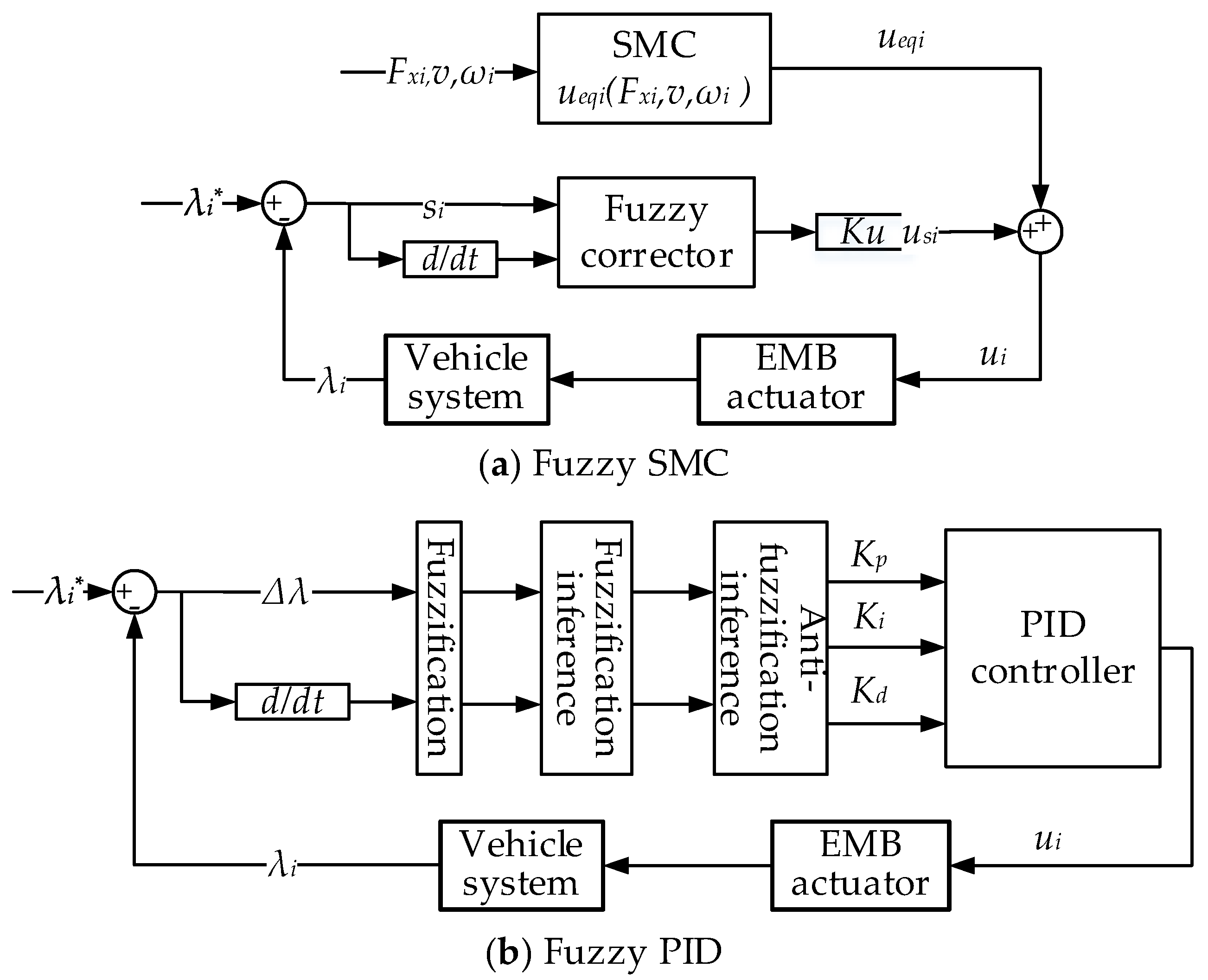
3.2.3. Fuzzy Control
3.2.4. Other Control Methods
3.3. Redundancy of BBW System
4. Application of BBW
4.1. Application of Anti-Lock Brake
4.2. Application in Electric Vehicles
5. Conclusions and Prospects
Author Contributions
Funding
Conflicts of Interest
References
- Yu, Z.; Han, W.; Xu, S.; Xiong, L. Review on Hydraulic Pressure Control of Electro-hydraulic Brake System. J. Mech. Eng. 2017, 53, 1–15. [Google Scholar] [CrossRef]
- Ahn, J.K.; Jung, K.H.; Kim, D.H.; Jin, H.B.; Kim, H.S.; Hwang, S.H. Analysis of a regenerative braking system for Hybrid Electric Vehicles using an Electro-Mechanical Brake. Int. J. Automot. Technol. 2009, 10, 229–234. [Google Scholar] [CrossRef]
- Hedenetz, B. Development framework for ultra-dependable automotive systems based on a time-triggered architecture. In Proceedings of the 1998 19th IEEE Real-Time Systems Symposium, Madrid, Spain, 2–4 December 1998; IEEE: Piscataway, NJ, USA, 1998. [Google Scholar]
- Ozdalyan, B. Development of a slip control anti-lock braking system model. Int. J. Automot. Technol. 2008, 9, 71–80. [Google Scholar] [CrossRef]
- Joa, E.; Yi, K.; Sohn, K.; Bae, H. Four-wheel independent brake control to limit tire slip under unknown road conditions. Control Eng. Pract. 2018, 76, 79–95. [Google Scholar] [CrossRef]
- Xiong, L.; Qian, C.; Yu, Z. Review on Composite Braking System of Electric Vehicle. Automob. Technol. 2015, 1, 1–8. [Google Scholar]
- Gong, X. Research on Control Technology of a Novel Brake-by-Wire System for Electric Vehicle; Nanjing University of Science & Technology: Nanjing, China, 2016. [Google Scholar]
- Yang, K. Research of Electromechanical Brake and Vehicle Stability Control System for Light Vehicle; Jilin University: Changchun, China, 2009. [Google Scholar]
- D’alfio, N.; Morgando, A.; Sorniotti, A. Electro-hydraulic brake systems: Design and test through hardware-in-the-loop simulation. Veh. Syst. Dyn. 2006, 44, 378–392. [Google Scholar] [CrossRef]
- Yong, J.; Gao, F.; Ding, N.; He, Y. Design and validation of an electro-hydraulic brake system using hardware-in-the-loop real-time simulation. Int. J. Automot. Technol. 2017, 18, 603–612. [Google Scholar] [CrossRef]
- Li, J.; Ding, M.; Yong, W.; Li, C. Evaluation and Optimization of the Nonlinear Flow Controllability of Switch Valve in Vehicle Electro-Hydraulic Brake System. IEEE Access 2018, 6, 31281–31293. [Google Scholar] [CrossRef]
- Yu, Z.; Wang, J.; Lu, X.; Xu, S. Hydraulic pressure control of electro-hydraulic brake system. Control Theory Appl. 2016, 33, 897–902. [Google Scholar]
- Zhang, F.; Wei, M. Multi-objective optimization of the control strategy of electric vehicle electro-hydraulic composite braking system with genetic algorithm. Adv. Mech. Eng. 2015, 7, 1687814014568491. [Google Scholar]
- Yu, Z.; Yu, M.; Xiong, L. Modeling and Controlling of Vehicle ESP Wheel Cylinder Pressure Based on AMESim. Automob. Technol. 2013, 449, 19–22. [Google Scholar]
- Mercorelli, P.; Werner, N. An Adaptive Resonance Regulator Design for Motion Control of Intake Valves in Camless Engine Systems. IEEE Trans. Ind. Electron. 2017, 64, 3413–3422. [Google Scholar] [CrossRef]
- Shen, C.; Wang, J.; Lin, Y. Study on Brake Actuator of Electro-mechanical Braking System. Trans. Chin. Soc. Agric. Mach. 2007, 38, 30–33. [Google Scholar]
- Park, G.; Choi, S.; Hyun, D. Clamping force estimation based on hysteresis modeling for electro-mechanical brakes. Int. J. Automot. Technol. 2017, 18, 883–890. [Google Scholar] [CrossRef]
- Xia, L.; Deng, Z. Optimal design of electromechanical brake actuator through an integrated mechatronic approach. J. Jilin Univ. Eng. Technol. Ed. 2012, 42, 1–9. [Google Scholar]
- Lee, C.F.; Manzie, C. Active Brake Judder Attenuation Using an Electromechanical Brake-by-Wire System. IEEE/ASME Trans. Mechatron. 2016, 21, 2964–2976. [Google Scholar] [CrossRef]
- Lee, C.F.; Manzie, C. Active Brake Torque Variation Compensation with Speed Scheduling of an Electromechanical Brake. In Proceedings of the FISITA World Automotive Congress, Beijing, China, 27–30 November 2012; Volume 5. [Google Scholar]
- Cheon, J.S.; Kim, J.; Jeon, J. New Brake By Wire Concept with Mechanical Backup. SAE Int. J. Passeng. Cars Mech. Syst. 2012, 5, 1194–1198. [Google Scholar] [CrossRef]
- Kim, J.; Jo, C.; Kwon, Y.; Cheon, J.S.; Park, S.J.; Jeon, G.B.; Shim, J. Electro-Mechanical Brake for Front Wheel with Back-up Braking. SAE Int. J. Passeng. Cars Mech. Syst. 2014, 7, 1369–1373. [Google Scholar] [CrossRef]
- Line, C.; Manzie, C.; Malcolm, G.C. Electromechanical Brake Modeling and Control: From PI to MPC. IEEE Trans. Control Syst. Technol. 2008, 16, 446–457. [Google Scholar] [CrossRef]
- Liu, G.; Song, J. Hardware-in-the-loop Test Bench for Electromechanical Brake System. Automot. Eng. 2006, 28, 929–932. [Google Scholar]
- Park, H.; Choi, S.B. Development of a Sensorless Control Method for a Self-Energizing Brake System Using Noncircular Gears. IEEE Trans. Control Syst. Technol. 2013, 21, 1328–1339. [Google Scholar] [CrossRef]
- Han, K.; Kim, M.; Huh, K. Modeling and control of an electronic wedge brake. Proc. Inst. Mech. Eng. Part C J. Mech. Eng. Sci. 2012, 226, 2440–2455. [Google Scholar] [CrossRef]
- Han, K.; Huh, K.; Hwang, W. EWB Control Based on the Estimated Clamping Force. In Proceedings of the SAE 2012 Brake Colloquium & Exhibition–30th Annual 2012, San Diego, CA, USA, 23–26 September 2012; SAE International: Warrendale, PA, USA, 2012; p. 2012-01-1797. [Google Scholar]
- Shin, D.H.; Lee, S.; Jeong, C.P.; Kwon, O.S.; Park, T.S.; Jin, S.H.; Ban, D.H.; Yang, S.H. Analytic approaches for keeping high braking efficiency and clamping efficiency of electro wedge brakes. Int. J. Precis. Eng. Manuf. 2015, 16, 1609–1615. [Google Scholar] [CrossRef]
- Amirhossein, G.; Reza, K. A New Approach to the Electronic Wedge Brake. In Proceedings of the SAE 2012 Brake Colloquium & Exhibition—30th Annual 2012, San Diego, CA, USA, 23–26 September 2012; SAE International: Warrendale, PA, USA, 2012; p. 2012-01-1801. [Google Scholar]
- Jo, C.H.; Lee, S.M.; Song, H.L.; Cho, Y.S.; Hyun, D.Y.; Kin, H.S. Design and Control of an Upper–Wedge -Type Electronic Brake. Proc. Inst. Mech. Eng. Part D J. Automob. Eng. 2010, 224, 1393–1405. [Google Scholar] [CrossRef]
- Shin, D.H.; Kwon, O.S.; Moon, J.I.; Yang, S.H. Cost-Effective Approaches of Circumferential Electro Wedge Brake for Reducing Unbalance-Wears. J. Mech. Eng. Autom. 2012, 2, 208–212. [Google Scholar]
- Todeschini, F.; Formentin, S.; Panzani, G.; Corno, M.; Savaresi, S.M.; Zaccarian, L. Nonlinear Pressure Control for BBW Systems via Dead-Zone and Antiwindup Compensation. IEEE Trans. Control Syst. Technol. 2016, 24, 1419–1431. [Google Scholar] [CrossRef]
- Castro, R.D.; Todeschini, F.; Araújo, R.E.; Savaresi, S.M.; Corno, M.; Freitas, D. Adaptive-robust friction compensation in a hybrid brake-by-wire actuator. Proc. Inst. Mech. Eng. Part I J. Syst. Control Eng. 2014, 228, 769–786. [Google Scholar] [CrossRef]
- Todeschini, F.; Corno, M.; Panzani, G.; Savaresi, S.M. Adaptive position–pressure control of a brake by wire actuator for sport motorcycles. Eur. J. Control 2014, 20, 79–86. [Google Scholar] [CrossRef]
- Todeschini, F.; Corno, M.; Panzani, G.; Fiorenti, S.; Savaresi, S.M. Adaptive Cascade Control of a Brake-by-Wire Actuator for Sport Motorcycles. IEEE/ASME Trans. Mechatron. 2015, 20, 1310–1319. [Google Scholar] [CrossRef]
- Dardanelli, A.; Alli, G.; Savaresi, S.M. Modeling and control of an electro-mechanical brake-by-wire actuator for a sport motorbike. IFAC Proc. Vol. 2010, 43, 524–531. [Google Scholar] [CrossRef]
- Gong, X.; Chang, S.; Jiang, L.; Li, X. Braking Method of Electric Vehicle Based on Direct Drive Electro- Hydraulic Brake Unit. Open Mech. Eng. J. 2015, 9, 351–360. [Google Scholar] [CrossRef] [Green Version]
- Gong, X.; Chang, S.; Jiang, L.; Li, X. A Novel Brake-by-Wire Unit and Control System for Electric Vehicle. J. Shanghai Jiao Tong Univ. 2016, 50, 395–400. [Google Scholar]
- Gong, X.; Ge, W.; Wang, L. A Brake-by-Wire Unit for Electric Vehicle; C.T.G. University: China, Chongqing, 2017. [Google Scholar]
- Zhang, J.; Liu, X.; Shi, Z. Design and Analysis of a Linear Generator with Improved Halbach PM Arrays. Small Spec. Electr. Mach. 2018, 46, 23–26. [Google Scholar]
- Gong, X.; Chang, S.; Jiang, L.; Li, X. Research on regenerative technology of EV based on direct-drive electric-hydraulic brake unit. In Proceedings of the 2015 IEEE International Conference on Mechatronics and Automation (ICMA), Beijing, China, 2–5 August 2015. [Google Scholar]
- Gong, X.; Chang, S.; Jiang, L.; Li, X. Research on regenerative brake technology of electric vehicle based on direct-drive electric-hydraulic brake system. Int. J. Veh. Des. 2016, 70, 1–28. [Google Scholar] [CrossRef]
- Li, X.; Chang, S.; Gong, X. Modeling of a new brake by wire system based on the direct-drive electro-hydraulic brake unit. In Proceedings of the 2015 IEEE Advanced Information Technology, Electronic and Automation Control Conference (IAEAC), Chongqing, China, 19–20 December 2015. [Google Scholar]
- Lee, C.F.; Manzie, C. High-Bandwidth Clamp Force Control for an Electromechanical Brake. SAE Int. J. Passeng. Cars Electron. Electr. Syst. 2012, 5, 590–599. [Google Scholar] [CrossRef]
- Leu, K.; Huang, H.; Chen, Y.Y.; Huang, L.R.; Ji, K.M. An intelligent brake-by-wire system design and analysis in accordance with ISO-26262 functional safety standard. In Proceedings of the 2015 International Conference on Connected Vehicles and Expo (ICCVE), Shenzhen, China, 19–23 October 2015. [Google Scholar]
- Gong, X.; Qian, L.; Ge, W.; Wang, L. Research on the Anti-Disturbance Control Method of Brake-by-Wire Unit for Electric Vehicles. World Electr. Veh. J. 2019, 10, 44. [Google Scholar] [CrossRef] [Green Version]
- Liao, J.; Wang, J. Research on the braking performance of electro-mechanical brake based on the hardware-in-the-loop simulation. Mechatron. Eng. Technol. 2009, 38, 26–29. [Google Scholar]
- Lee, K.J.; Kwon, J.M.; Cheon, J.S.; Ahn, H.S. Hardware-in-the-Loop Simulation of Brake-by-Wire Systems with FlexRay Communication. In Proceedings of the 32nd Annual SAE Brake Colloquium & Exhibition, Burlingame, CA, USA, 5–8 October 2014; SAE International: Detroit, MI, USA. [Google Scholar]
- Semmler, S.; Fischer, D.; Isermann, R.; Schwarz, R.; Rieth, P. Estimation of vehicle velocity using brake-by-wire actuators. IFAC Proc. Vol. 2002, 35, 169–174. [Google Scholar] [CrossRef] [Green Version]
- Werner, B.; Aleksandar, V.; Gordana, P.; Oscar, D.M. Micro Torque Measurement Based on the Cable Brake Principle. In Proceedings of the First IEEE International Conference on Sensors—IEEE Sensors 2002, Orlando, FL, USA, 12–14 June 2002; Institute of Electrical and Electronics Engineers Inc: Piscataway, NJ, USA, 2002. [Google Scholar]
- Hong, D.; Hwang, I.; Yoon, P.; Huh, K. Development of a Vehicle Stability Control System Using Brake-by-Wire Actuators. J. Dyn. Syst. Meas. Control 2008, 130, 011008. [Google Scholar] [CrossRef]
- Ki, Y.H.; Lee, K.J.; Cheon, J.S.; Ahn, H.S. Design and implementation of a new clamping force estimator in Electro-Mechanical Brake systems. Int. J. Automot. Technol. 2013, 14, 739–745. [Google Scholar] [CrossRef]
- Kwak, J.; Yao, B.; Bajaj, A. Analytical Model Development and Model Reduction for Electromechanical Brake System. In Proceedings of the 2004 ASME International Mechanical Engineering Congress and Exposition 2004, Anaheim, CA, USA, 13–19 November 2004; p. 61955. [Google Scholar]
- Hoseinnezhad, R.; Bab-Hadiashar, A.; Rocco, T. Real-Time Clamp Force Measurement in Electromechanical Brake Calipers. IEEE Trans. Veh. Technol. 2008, 57, 770–777. [Google Scholar] [CrossRef]
- Saric, S.; Bab-Hadiashar, A.; Walt, J.V.D. Estimating clamp force for brake-by-wire systems: Thermal considerations. Mechatronics 2009, 19, 886–895. [Google Scholar] [CrossRef]
- Saric, S.; Bab-Hadiashar, A.; Hoseinnezhad, R. Clamp-Force Estimation for a Brake-by-Wire System: A Sensor-Fusion Approach. IEEE Trans. Veh. Technol. 2008, 57, 778–786. [Google Scholar] [CrossRef]
- Hoseinnezhad, R. Position sensing in brake-by-wire callipers using resolvers. IEEE Trans. Veh. Technol. 2006, 55, 924–932. [Google Scholar] [CrossRef]
- Lee, C.F.; Manzie, C. Rapid parameter identification for an electromechanical brake. In Proceedings of the 2013 Australian Control Conference, Perth, WA, Australia, 4–5 November 2013; IEEE Computer Society: Piscataway, NJ, USA, 2013. [Google Scholar]
- Shyrokau, B.; Wang, D.; Augsburg, K.; Ivanov, V. Vehicle dynamics with brake hysteresis. Proc. Inst. Mech. Eng. Part D J. Automob. Eng. 2013, 227, 139–150. [Google Scholar] [CrossRef] [Green Version]
- Jo, C.; Hwang, S.; Kim, H. Clamping-Force Control for Electromechanical Brake. IEEE Trans. Veh. Technol. 2010, 59, 3205–3212. [Google Scholar] [CrossRef]
- Xia, L.; Deng, Z. Calculation and Analysis of Friction Torque and Energy Dissipation of Electromechanical Brake Actuator. J. Hunan Univ. Nat. Sci. 2018, 45, 48–56. [Google Scholar]
- Lindvai-Soos, D.; Horn, M. Modelling, control & implementation of an electro-mechanic braking force actuator for HEV and EV. IFAC Proc. Vol. 2013, 46, 620–625. [Google Scholar]
- Li, D.; Zhang, L.; He, B. Fuzzy Control Based on Vehicle Slip-ratio for Electro-mechanical Braking Systems. J. Mech. Eng. 2012, 48, 124–129. [Google Scholar] [CrossRef]
- Ge, Z.; Wang, W.; Wang, J. Control strategy for brake clearance adjustment of electronic mechanical brake. J. Zhejiang Univ. Eng. Sci. 2017, 51, 138–144. [Google Scholar]
- Line, C.; Manzie, C.; Good, M. Control of an Electromechanical Brake for Automotive Brake-by-Wire Systems with an Adapted Motion Control Architecture. In Proceedings of the SAE 2004 Automotive Dynamics, Stability & Controls Conference and Exhibition, Burlingame, PA, USA, 5–8 October 2004; SAE International: Warrendale, PA, USA, 2004; p. 2004-01-2050. [Google Scholar]
- Yang, K.; Li, J.; Guo, L.; Li, Y. Design and Simulation of Electromechanical Brake System. Trans. Chin. Soc. Agric. Mach. 2008, 39, 24–27. [Google Scholar]
- Baek, S.K.; Oh, H.K.; Park, J.H.; Shin, Y.J.; Kin, S.W. Evaluation of Efficient Operation for Electromechanical Brake Using Maximum Torque per Ampere Control. Energies 2019, 12, 1869. [Google Scholar] [CrossRef] [Green Version]
- Atia, M.R.A.; Haggag, S.A.; Kamal, A.M.M. Enhanced Electromechanical Brake-by-Wire System Using Sliding Mode Controller. J. Dyn. Syst. Meas. Control 2016, 138. [Google Scholar] [CrossRef]
- Lee, C.F.; Manzie, C. Near-time-optimal tracking controller design for an automotive electromechanical brake. Proc. Inst. Mech. Eng. Part I J. Syst. Control Eng. 2011, 226, 537–549. [Google Scholar] [CrossRef]
- Peng, X.; He, L.; Lv, Y. Fuzzy sliding mode control based on vehicle slip ratio for electro-mechanical braking systems. J. Cent. South Univ. Sci. Technol. 2018, 49, 360–370. [Google Scholar]
- Kim, K.; Li, Q.; Park, C.; Hwang, K. A Design of Intelligent Actuator Logic using Fuzzy Control for EMB System. In Proceedings of the International MultiConference of Engineers and Computer Scientists, Hong Kong, China, 16–18 March 2011. [Google Scholar]
- Li, B.; Tian, H.S.; Wang, R.; Dong, X.; Zhang, X. Design of torque motor controller in EMB based on FPGA. Mach. Des. Manuf. 2010, 6, 9–11. [Google Scholar]
- Peng, X.; Jia, M.; He, L.; Yu, X.; Lv, Y. Fuzzy sliding mode control based on longitudinal force estimation for electro-mechanical braking systems using BLDC motor. CES Trans. Electr. Mach. Syst. 2018, 2, 142–151. [Google Scholar]
- Yang, K.; Li, J.; Li, Y.; Tan, S.; Wei, Q.; Tang, L. Study of EBD/ABS Based on Electromechanical Brake System. J. Syst. Simul. 2009, 21, 1785–1788. [Google Scholar]
- Xiang, W.; Richardson, P.C.; Zhao, C.; Mohammad, S. Automobile Brake-by-Wire Control System Design and Analysis. IEEE Trans. Veh. Technol. 2008, 57, 138–145. [Google Scholar] [CrossRef]
- Benine-Neto, A.; Moreau, X.; Lanusse, P. Robust control for an electro-mechanical anti-lock braking system: The CRONE approach. IFAC-PapersOnLine 2017, 50, 12575–12581. [Google Scholar] [CrossRef]
- Hwang, W.; Huh, K. Fault Detection and Estimation for Electromechanical Brake Systems Using Parity Space Approach. J. Dyn. Syst. Meas. Control 2014, 137. [Google Scholar] [CrossRef]
- Milanés, V.; González, C.; Naranjo, J.E.; Onieva, E.; De Pedro, T. Electro-hydraulic braking system for autonomous vehicles. Int. J. Automot. Technol. 2010, 11, 89–95. [Google Scholar] [CrossRef]
- Lee, K.J.; Ki, Y.H.; Cheon, J.S.; Hwang, G.; Ahn, H.S. Approach to functional safety-compliant ECU design for electro-mechanical brake systems. Int. J. Automot. Technol. 2014, 15, 325–332. [Google Scholar] [CrossRef]
- Liu, H.; Deng, W.; He, R.; Wu, J.; Zhu, B. Fault-Tolerant Control of Brake-by-Wire Systems Based on Control Allocation. In Proceedings of the SAE 2016 World Congress and Exhibition, Detroit, MI, USA, 12–14 April 2016; SAE International: Warrendale, PA, USA, 2016; p. 2016-01-0132. [Google Scholar]
- Hermann, K.; Gunther, B.; Stefan, P. Tolerating arbitrary node failures in the time-triggered architecture. In Proceedings of the SAE 2001 World Congress, Detroit, MI, USA, 5–8 March 2001; SAE International: Warrendale, PA, USA, 2001. [Google Scholar]
- Wang, Z.; Yu, L.; You, C.; Wang, Y.; Song, J. Fail-safe control allocation for a distributed brake-by-wire system considering the driver’s behaviour. Proc. Inst. Mech. Eng. Part D J. Automob. Eng. 2014, 228, 1547–1567. [Google Scholar] [CrossRef]
- Anwar, S.; Zheng, B. An Antilock-Braking Algorithm for an Eddy-Current-Based Brake-by-Wire System. IEEE Trans. Veh. Technol. 2007, 56, 1100–1107. [Google Scholar] [CrossRef]
- Tanelli, M.; Sartori, R.; Savaresi, S.M. Sliding mode slip-deceleration control for brake-by-wire control systems. IFAC Proc. Vol. 2007, 40, 135–142. [Google Scholar] [CrossRef]
- Cheon, J.S. Brake by Wire System Configuration and Functions using Front EWB (Electric Wedge Brake) and Rear EMB (Electro-Mechanical Brake) Actuators. SAE Tech. Pap. Ser. 2010. [Google Scholar] [CrossRef]
- Kun, Y.; Li, J.; Li, Y.; Rong, R.; Tan, S.; Guo, L. Application of Electromechanical Brake System in Ada ptive Cruise Control. Trans. Chin. Soc. Agric. Mach. 2008, 39, 34–38. [Google Scholar]
- Peng, X.; Chen, C.; Zhang, J. Study of the Sliding Mode Control of Electromechanical Brake Systems. J. Hunan Univ. Nat. Sci. 2010, 37, 35–39. [Google Scholar]
- Zhou, S.; Chen, Q.; Sun, D. Variable Structure Control with Sliding Mode for ABS of Vehicle Based on EMB System. J. Northeast. Univ. Nat. Sci. 2016, 37, 994–997. [Google Scholar]
- Zhao, G.; Wei, M. Effect of the Characteristics of Power Supply on the Anti-lock Braking Behaviors of a Brake-by-wire System. Mech. Sci. Technol. Aerosp. Eng. 2011, 30, 108–111. [Google Scholar]
- Anwar, S. Anti-Lock Braking Control of a Hybrid Brake-by-Wire System. Proc. Inst. Mech. Eng. Part D J. Automob. Eng. 2006, 220, 1101–1117. [Google Scholar] [CrossRef]
- Tanelli, M.; Sartori, R.; Savaresi, S.M. Combining Slip and Deceleration Control for Brake-by-wire Control Systems: A Sliding-mode Approach. Eur. J. Control 2007, 13, 593–611. [Google Scholar] [CrossRef]
- Shiao, Y.; Nguyen, Q.A.; Lin, J.W. A Study of Novel Hybrid Antilock Braking System Employing Magnetorheological Brake. Adv. Mech. Eng. 2014, 2014, 617584. [Google Scholar] [CrossRef]
- Suzuki, Y.; Kano, Y.; Abe, M. A study on tyre force distribution controls for full drive-by-wire electric vehicle. Veh. Syst. Dyn. 2014, 52 (Suppl. S1), 235–250. [Google Scholar] [CrossRef]
- Zhang, L.; Yu, L.; Wang, Z.; Zuo, L.; Song, L. All-Wheel Braking Force Allocation During a Braking-in-Turn Maneuver for Vehicles With the Brake-by-Wire System Considering Braking Efficiency and Stability. IEEE Trans. Veh. Technol. 2016, 65, 4752–4767. [Google Scholar] [CrossRef]
- Anwar, S. Generalized predictive control of yaw dynamics of a hybrid brake-by-wire equipped vehicle. Mechatronics 2005, 15, 1089–1108. [Google Scholar] [CrossRef]
- Tanelli, M.; Astolfi, A.; Savaresi, S.M. Robust nonlinear output feedback control for brake by wire control systems. Automatica 2008, 44, 1078–1087. [Google Scholar] [CrossRef]
- Kim, D.; Kim, C.; Hwang, S.; Kim, H. Hardware in the Loop Simulation of Vehicle Stability Control using Regenerative Braking and Electro Hydraulic Brake for Hybrid Electric Vehicle. IFAC Proc. Vol. 2008, 41, 5664–5669. [Google Scholar] [CrossRef] [Green Version]
- Ko, J.; Ko, S.; Son, H.; Yoo, B.; Cheon, J.; Kim, H. Development of Brake System and Regenerative Braking Cooperative Control Algorithm for Automatic-Transmission-Based Hybrid Electric Vehicles. IEEE Trans. Veh. Technol. 2015, 64, 431–440. [Google Scholar] [CrossRef]
- Ko, J.; Ko, S.; Bak, Y.; Jang, M.; Yoo, B.; Cheon, J.; Kim, H. Development of regenerative braking co-operative control system for automatic transmission-based hybrid electric vehicle using electronic wedge brake. In Proceedings of the 2013 World Electric Vehicle Symposium and Exhibition (EVS27), Barcelona, Spain, 17–20 November 2013. [Google Scholar]
- Kim, D.H.; Kim, J.M.; Hwang, S.H.; Kim, H.S. Optimal brake torque distribution for a four-wheeldrive hybrid electric vehicle stability enhancement. Proc. Inst. Mech. Eng. Part D J. Automob. Eng. 2007, 221, 1357–1366. [Google Scholar] [CrossRef]
- Yang, K.; Gao, S.; Wang, J.; Li, J.; Liu, R.; Xu, J.C. A Study of Decoupled Brake Energy Recovery System Based on Electro-mechanical Brake. Automot. Eng. 2016, 38, 1072–1079. [Google Scholar]
- Ma, B.; Lin, M.; Chen, Y.; Wang, L. Investigation of energy efficiency for electro-hydraulic composite braking system which is based on the regenerated energy. Adv. Mech. Eng. 2016, 8, 1687814016666449. [Google Scholar] [CrossRef] [Green Version]
- Wang, Z.; Ma, C.; Wang, F. An Analysis on the Braking Energy Regeneration in Electro-mechanical Braking System. Automot. Eng. 2010, 32, 972–976. [Google Scholar]
- He, C.; Wang, G.; Gong, Z.; Xing, Z.; Xu, D. A Control Algorithm for the Novel Regenerative—Mechanical Coupled Brake System with by-Wire Based on Multidisciplinary Design Optimization for an Electric Vehicle. Energies 2018, 11, 2322. [Google Scholar] [CrossRef] [Green Version]
- Li, L.; Li, X.; Wang, X.; Liu, Y.; Song, J.; Ran, X. Transient switching control strategy from regenerative braking to anti-lock braking with a semi-brake-by-wire system. Veh. Syst. Dyn. 2016, 54, 231–257. [Google Scholar] [CrossRef]
- Wang, C.; Zhao, W.; Li, W. Braking sense consistency strategy of electro-hydraulic composite braking system. Mech. Syst. Signal Process. 2018, 109, 196–219. [Google Scholar] [CrossRef]


| Vehicle Load | 100 km Consumed Energy (kW·h) | C Saved Energy (kW·h) | C Improvement Ratio (%) | ||||
|---|---|---|---|---|---|---|---|
| A | B | C | Compared with A | Compared with B | Compared with A | Compared with B | |
| No load | 95.67 | 76.92 | 59.19 | 36.48 | 17.73 | 38.17 | 23.05 |
| Half load | 115.1 | 93.23 | 73.00 | 42.07 | 20.23 | 36.56 | 21.70 |
| 60% load | 119.0 | 96.48 | 75.87 | 43.12 | 20.61 | 36.24 | 21.36 |
| 80% load | 126.9 | 103.17 | 81.88 | 45.02 | 21.29 | 35.48 | 20.64 |
| Full load | 135.0 | 109.98 | 88.14 | 46.81 | 21.84 | 34.69 | 19.86 |
| A: Bus without recovery system B: Bus with traditional recovery system C: Bus with EMB recovery system | |||||||
© 2020 by the authors. Licensee MDPI, Basel, Switzerland. This article is an open access article distributed under the terms and conditions of the Creative Commons Attribution (CC BY) license (http://creativecommons.org/licenses/by/4.0/).
Share and Cite
Gong, X.; Ge, W.; Yan, J.; Zhang, Y.; Gongye, X. Review on the Development, Control Method and Application Prospect of Brake-by-Wire Actuator. Actuators 2020, 9, 15. https://doi.org/10.3390/act9010015
Gong X, Ge W, Yan J, Zhang Y, Gongye X. Review on the Development, Control Method and Application Prospect of Brake-by-Wire Actuator. Actuators. 2020; 9(1):15. https://doi.org/10.3390/act9010015
Chicago/Turabian StyleGong, Xiaoxiang, Weiguo Ge, Juan Yan, Yiwei Zhang, and Xiangyu Gongye. 2020. "Review on the Development, Control Method and Application Prospect of Brake-by-Wire Actuator" Actuators 9, no. 1: 15. https://doi.org/10.3390/act9010015
APA StyleGong, X., Ge, W., Yan, J., Zhang, Y., & Gongye, X. (2020). Review on the Development, Control Method and Application Prospect of Brake-by-Wire Actuator. Actuators, 9(1), 15. https://doi.org/10.3390/act9010015