Article

Damage Detection Using d15 Piezoelectric Sensors in a Laminate Beam Undergoing Three-Point Bending

1
Department of Engineering, University of Jamestown, Jamestown, ND 58405, USA
2
Mechanical Engineering Department, University of Wisconsin-Milwaukee, Milwaukee, WI 53211, USA
*
Author to whom correspondence should be addressed.
Actuators 2019, 8(4), 70; https://doi.org/10.3390/act8040070
Submission received: 27 July 2019 / Revised: 7 September 2019 / Accepted: 24 September 2019 / Published: 29 September 2019

Abstract

:
A major inhibition to the widespread use of laminate structures is the inability of nondestructive testing techniques to effectively evaluate the bondline integrity. This work proposes and analyzes a bondline-integrity health monitoring approach utilizing shear-mode (d15) piezoelectric transducers. The d15 transducers were embedded in the bondlines of symmetric laminate structures to monitor and evaluate the bondline integrity using ultrasonic inspection. The d15 piezoelectric transducers made of lead zirconate titanate (PZT) enabled ultrasonic inspection of bonds by actuating and sensing antisymmetric waves in laminate structures. Design considerations, fabrication process, and experimental methods for testing a laminate specimen are presented. Designs included bondline-embedded d15 PZT piezoelectric transducers with surface-mounted transverse (d31) piezoelectric transducers for signal comparison. Defects in the bondline were created by a quasi-static three-point bending test, with results showing the ability of d15 piezoelectric transducers to detect bondline damage. Two damage indices based on Pearson correlation coefficient and normalized signal energy were implemented to evaluate the presence of damage and its severity. The experimental results demonstrate the ability of bondline-embedded d15 piezoelectric transducers to be used as actuators and sensors for ultrasonic health monitoring of bondline integrity. A comparison between surface-mounted d31 PZT and bondline-embedded d15 PZT sensors was also conducted. It was seen that signals sensed by bondline-embedded d15 PZTs showed higher distortion due to bondline defects compared with the sensed signals from the surface-mounted d31 PZT.

1. Introduction

Ultrasonic non-destructive testing and evaluation (NDT/E) techniques are commonly used for inspection of structures including complex laminate structures. However, a major roadblock to the widespread use of laminate structures is the inability of NDT/E techniques to effectively discriminate between a pristine bond and a damaged bond [1]. As a result, use of adhesive bonding is limited to secondary loaded structures or reinforced with mechanical fasteners negating some of its benefits. Ultrasonic structural health monitoring (SHM) methods employ embedded sensors with the goals of automating damage detection to improve safety and reliability while reducing maintenance costs in engineering structures. The use of internally embedded sensors presents new opportunities to inspect laminate structures with the potential to expand the use of laminate structures beyond their current limit. Various researchers have experimented with internally embedded bondline damage detection using electromechanical impedance methods [2,3]. This paper presents a study into ultrasonic health monitoring of adhesive joints using shear-mode piezoelectric transducers internally embedded within the bondline of laminate structures.
Ultrasonic inspection methods such as conventional ultrasonic C-scan (two dimensions imaging technique) and contact ultrasonic testing have been used to detect surface and joint defects in composite and laminate structures [4,5,6,7,8,9,10]. Ultrasonic shear waves [4] and fundamental mode antisymmetric Lamb (A0) waves [5] propagating in laminate structures have been consistently found to be more sensitive to joint defects than axial and symmetric Lamb (S0) waves. The A0 mode was also used to inspect composite laminates containing delamination at different interfaces by employing air-coupled ultrasonic transducers [6]. In other studies, standard wedge ultrasonic transducers were employed to actuate high frequency guided waves including S0 and A0 modes for detection of small notches in a multilayered structure consisting of two adhesively bonded aluminum plates [7]. Their results showed that the guided waves can be used for detection of hidden defects. Ultrasonic methods provide a viable solution for detection of joint defects but these inspection methods and NDT/E techniques in general are often expensive, require access to inspect a region, cannot be easily used on large structures, and lack the means to measure the bond strength [11,12,13].
Recent research has developed methods for bondline inspection using electromechanical impedance (EMI) methods employing surface-mounted and bondline-embedded lead zirconate titanate (PZT) transducers. Investigations included the use of EMI methods to monitor the degradation of bonded joints [14] and to measure the adhesive bond strength by analyzing the characteristics of EMI response [15]. In these experiments, contamination of the bond interface and altering the curing temperature were used to control the level of ‘damage’. Previous studies also examined the effects of embedding piezoelectric transducers into adhesive bond joints on EMI response and strain wave actuation and sensing intended for bondline inspection [2,3,16]. While many promising results have been achieved in detecting joint defects with embedded PZT transducers, EMI inspection is limited to the region adjacent to the PZT transducers.
Ultrasonic guided wave-based inspection techniques offer a wide-area coverage with a relatively small number of sensors. Fundamental Lamb (S0 and A0) modes were investigated extensively for damage detection in laminate structures using piezoelectric wafer active sensors (PWAS), actuated based on the d31 property, mounted on the surface [17,18,19,20]. The A0 Lamb waves generated by surface-mounted d31 PZTs were found to effectively detect delaminations in a composite beam [17] and to identify damage in a foam core of a sandwich plate [18]. The PZT actuators were excited at low actuation frequency (<100 kHz) to ensure the dominance of A0 mode in the inspected structure.
Recently there has been increasing interest in using shear-mode PZTs, including d15 PZTs and d36 PZTs, for SHM applications due to their unique characteristics in actuating and sensing ultrasonic waves when mounted on the surface or embedded within the bondline of laminate structures [21,22,23,24,25,26]. Square d15 piezoelectric transducers attached to the surface of aluminum plates were studied through simulation and experiments [21]. They were found to generate maximum fundamental Lamb modes (A0 and S0) in their polarization direction while shear horizontal (SH) waves were dominant in the perpendicular direction. Another study focused on the properties of ultrasonic waves actuated and sensed by d15 PZT transducers internally embedded within the bondline of laminate structures [16,25]. It was found that the elastic waves generated by d15 PZT actuators along their polarization direction exhibit the characteristics of antisymmetric (flexural) waves coupled with strong transverse shear stress across the bondlines. The ultrasonic waves of square d36 piezoelectric actuators mounted on the surface of an aluminum plate were also investigated [24]. This type of piezoelectric actuator was found to generate SH waves in the orthogonal directions while maximum fundamental Lamb modes propagated in the polarization direction. Similarly, they were also used for detection of surface defects [22]. The majority of state-of-the-art methods explored have employed shear-mode piezoelectric transducers adhered to an external surface for damage detection in plate-like structures.
This paper presents an investigation into the ability of d15 PZT transducers embedded inside a laminate structure to monitor adhesive joint integrity using ultrasonic wave propagation methods during a destructive three-point bending test. The shear-mode PZTs have a stronger piezoelectric coupling (d15) than d31 or d33, making them efficient for actuation and sensing shear strains [27]. Placing d15 PZT transducers at the mid-plane of a laminate structure results in selective actuation and sensing of antisymmetric waves which have been found to be sensitive to joint defects due to direct coupling between transverse shear and bending. This approach places the transducers in direct contact with the bondline of interest. Also, embedding d15 PZT actuators inside the structure provides them with supporting material to act against, which should result in higher actuation strength than if they were lacking the structure against which to react.
In this paper, the ultrasonic waves generated by bondline-embedded d15 PZTs in a pitch–catch configuration were examined. A d31 PZT sensor was also mounted on the surface of the laminate structure for comparison purposes. EMI analysis of d15 PZTs was implemented to monitor the integrity of the piezoelectric transducers themselves during the experiment. A three-point bending test was performed cyclically to produce increasing joint defects by applying a quasi-static load at mid-span of the structure. The waveform signals obtained from d15 PZT and d31 PZT sensors were processed for evaluation of bondline integrity through damage index methods and comparison of waveform signals from pristine and damaged states. Finally, the main findings from this research as well as future extensions of the proposed methodology are presented.

2. Theoretical Background

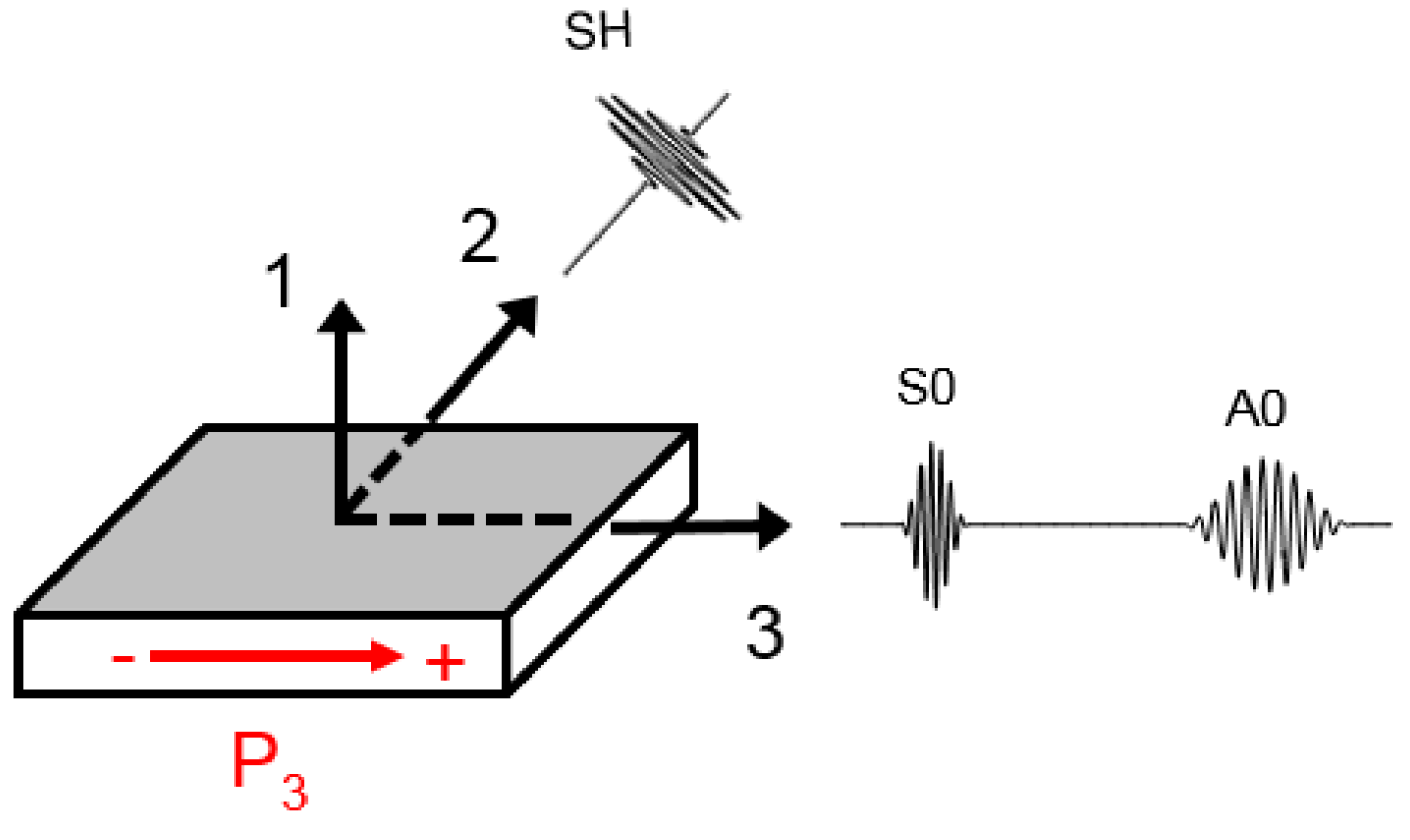
2.1. Shear-Mode (d15) PZTs

The relation between the mechanical and the electrical properties are expressed in IEEE standard format [28] as:
S i j = s i j k l E T k l + d k i j E k
D i = d i k l T k l + ε i k T E k
In Equations (1) and (2), S i j is the mechanical strain, s i j k l E is the material compliance coefficient at zero electrical field, T k l is the mechanical stress, E k is the electrical field, D i is the electrical displacement, ε i k T is the material dielectric permittivity at zero mechanical stress, d k i j and d i k l are the piezoelectric coupling coefficients between mechanical and electrical domains. Shear-mode piezoelectric transducers polarized in the 3 –direction with an electric field applied in the 1 –direction will undergo shear motion in 1 3 plane and decoupled shear strains among the principal planes. Therefore, the general constitutive equations for a shear-mode (d15) piezoelectric transducer having a linear relation between the mechanical and the electrical properties are [28]:
S 5 = s 55 E T 5 + d 15 E 1
D 1 = d 15 T 5 + ε 11 T E 1
Equation (3) represents the converse piezoelectric effects of shear-mode transducers where the applied electric field, E 1 across its thickness induces the mechanical shear strain, S 5 in the 1–3 plane. Equation (4) represents the direct piezoelectric effects, where the applied shear stress, T 5 induces the electric displacement, D 1 .
As previously mentioned in Section 1, d15 PZT actuators are capable of simultaneously generating fundamental Lamb waves (S0 and A0 modes) and shear horizontal waves. Actuation and propagation direction for the fundamental wave and shear horizontal wave modes are shown in Figure 1. Depending on the frequency-thickness product, the contribution of each wave mode may vary, and higher modes can also exist in the medium. Additionally, the location of the transducer will affect its coupling to the structure and wave propagation modes. When d15 PZT actuator is subjected to a time-varying voltage on its surface electrodes, the first symmetric S0 mode is expected to propagate in 3–direction with particle motion aligned along its propagation direction. Similarly, the A0 mode which is characterized by particle motion in 1–direction. The direction of A mode propagation is predicted to travel along with S0 in the polarization direction of the actuator. However, the shear horizontal waves are predicted to propagate in 2–direction with their particle motion in 3–direction.
Several experiments and extensive simulation of d15 PZT have been conducted in literature to study the characteristics of ultrasonic waves generated by d15 PZTs mounted on the surfaces of plates [21] and internally embedded within the bondline of laminate structures [25]. It should also be mentioned that at relatively low actuation frequency, the behavior of fundamental Lamb waves (S0 and A0 modes) propagating in a plate-like structure approach the behavior of flexural waves and axial waves, respectively [29].

2.2. Damage Index

Damage indices are scalar quantities used in structural health monitoring and damage assessment to provide a measure of the difference between two signals produced by the same entity. In literature, many damage indices have been defined that have different sensitivities to signal changes and therefore to different types of damage. In this study, two damage indices were employed to detect and evaluate bondline integrity: Pearson correlation coefficient (PCC), and normalized signal energy (NSE) [30,31]. Existing literature indicates that PCC was found to show uniform and consistent increase in magnitude with the increase in damage severity (size) compared to root-mean-square deviation (RMSD) and mean absolute percentage deviation (MAPD) methods [32]. NSE is inherently sensitive to signal amplitude and therefore selected to measure the attenuation in waveform signals. It was shown in the literature that Pearson correlation coefficient is more sensitive to phase shifts in received signals while the normalized signal energy method was found to be more sensitive to amplitude of waveform signals. Therefore, the PCC and NSE methods were used to process waveform signals in the time domain as:
c o v ( X , x ) = 1 N i = 1 N ( X i X ¯ ) ( x i x ¯ )
P C C = c o v ( X , x ) σ X σ x
N S E = i = 1 N X i 2 i = 1 N x i 2 i = 1 N X i 2
where X ¯ and x ¯ are the means of the pristine waveform and the comparison signal, respectively, cov ( X , x ) is covariance, σ X and σ x are the standard deviations, X i is the pristine state at the ith measurement point, x i is the comparison signal (damaged state) at ith measurement point, and N is the number of measurements. For the sake of consistency between PCC and NSE, the damage index based on PCC was calculated as 1 − PCC such that zero value indicates that no damage exists while a value of one denotes complete failure.

3. Experiment

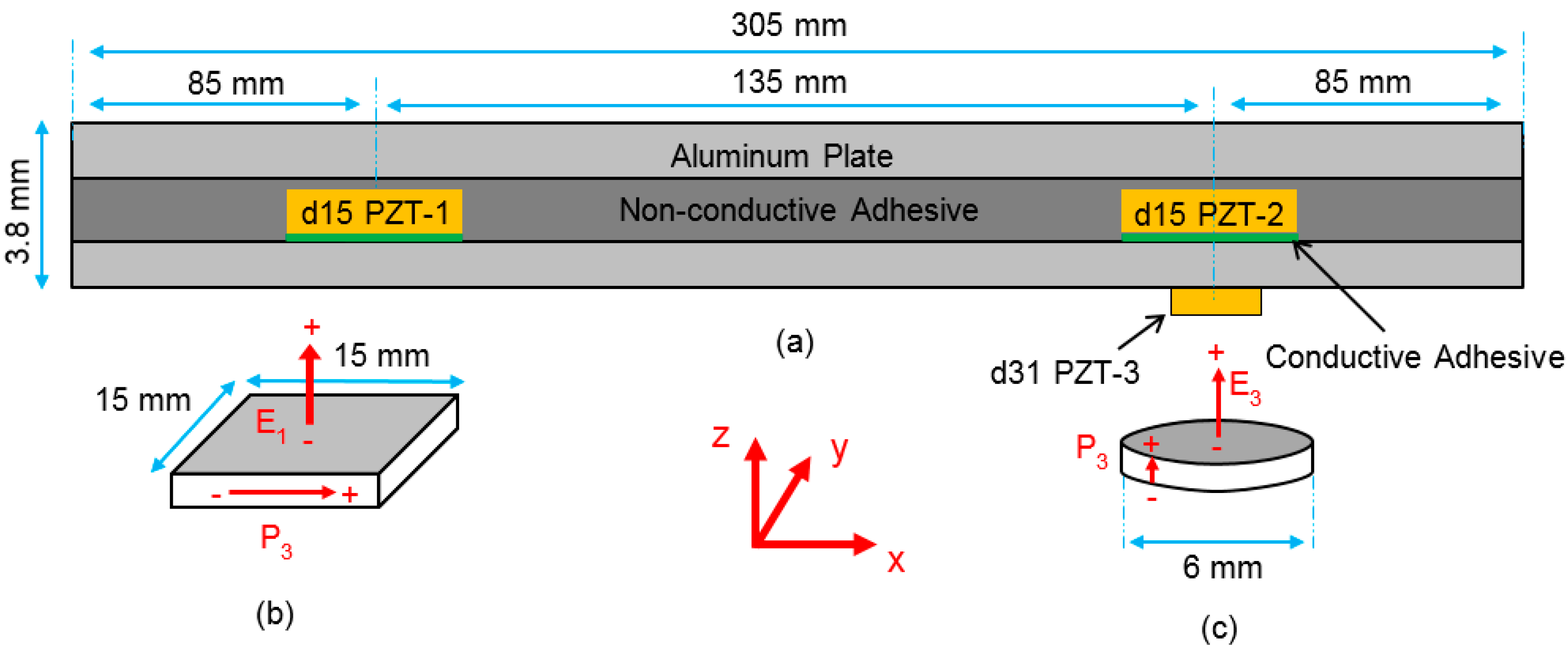
3.1. Specimen Design and Fabrication

A laminate specimen was carefully designed to investigate the use of bondline-embedded d15 PZT piezoelectric transducers to monitor the bondline integrity using ultrasonic guided waves. The specimen consisted of two adhesively bonded aluminum sheets with two d15 PZT transducers embedded inside the bondline at the mid-plane of the symmetric structure. A surface-mounted d31 PZT sensor was also integrated into the specimen for comparison and analyses. A schematic diagram of the laminate specimen is shown in Figure 2. The global coordinates <x, y, z> are aligned with the length, width, and thickness of the overall plate, respectively, as shown in Figure 2. The direction of positive polarization (P) for piezoelectric transducers defines the <3> axis of a local piezoelectric coordinate system of <1, 2, 3>. Therefore, the d15 piezoelectric transducer is embedded within the plate with the <3> aligned with <x>, <2> aligned with <-y>, and <1> aligned with <z>.
The 6061-T6 aluminum sheets measured 305 mm × 15 mm × 1 mm. The d15 PZT and d31 PZT transducers were made of APC 850 piezoceramic material (a Navy II material). Material properties of the laminate specimen including shear-mode PZT transducers are given in Table 1. The d15 PZT transducers which measured 1 mm × 15 mm × 15 mm were adhered on the surface of one aluminum sheet using Chemtronics CircuitWorks (CW2400) conductive epoxy. This aluminum sheet also served as a common ground for the PZT transducers. The d15 PZTs were placed 135 mm apart on center and 85 mm from the end boundaries with their polarization direction aligned along the length of aluminum sheet in the <x> direction. Thin wires were attached to the hot terminals of the d15 PZTs using the same conductive epoxy. The aluminum sheets were then bonded together using Hysol EA 9394 nonconductive epoxy in order to protect the hot terminals from shorting against the ground terminal (the bottom aluminum sheet). The adhesive layer thickness was controlled by placing 1.75-mm-thick spacers and applying low, uniform pressure on the specimen while curing. The adhesive thickness was measured at 1.8 ± 0.2 mm after curing. A round d31 PZT with 6 mm diameter and 0.25 mm thickness was then attached on the surface of the bottom aluminum sheet (ground terminal) using CW2400 conductive epoxy. The center of d31 PZT was aligned to coincide with the center of d15 PZT-2 making both transducers equidistant from d15 PZT-1.

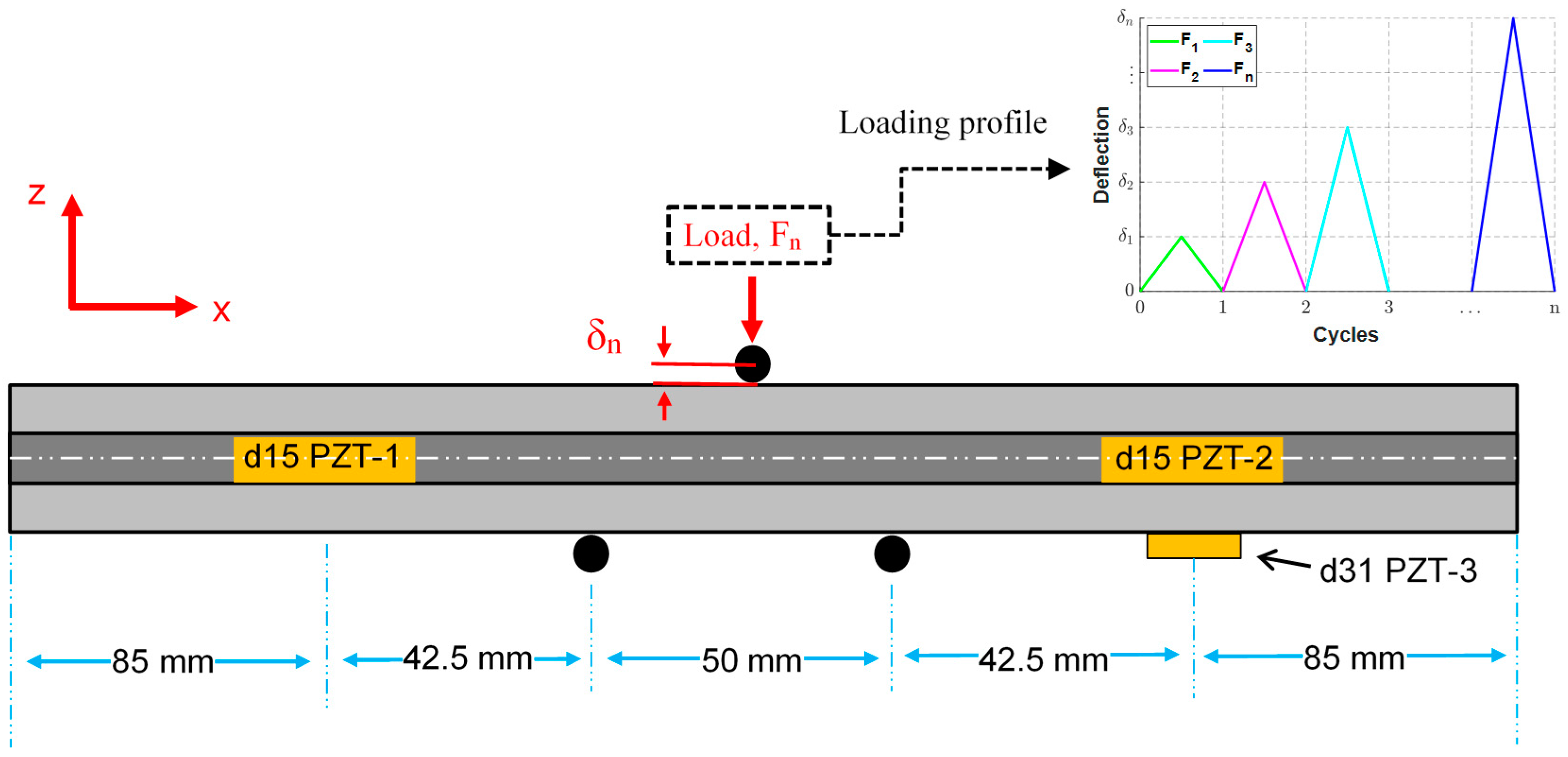
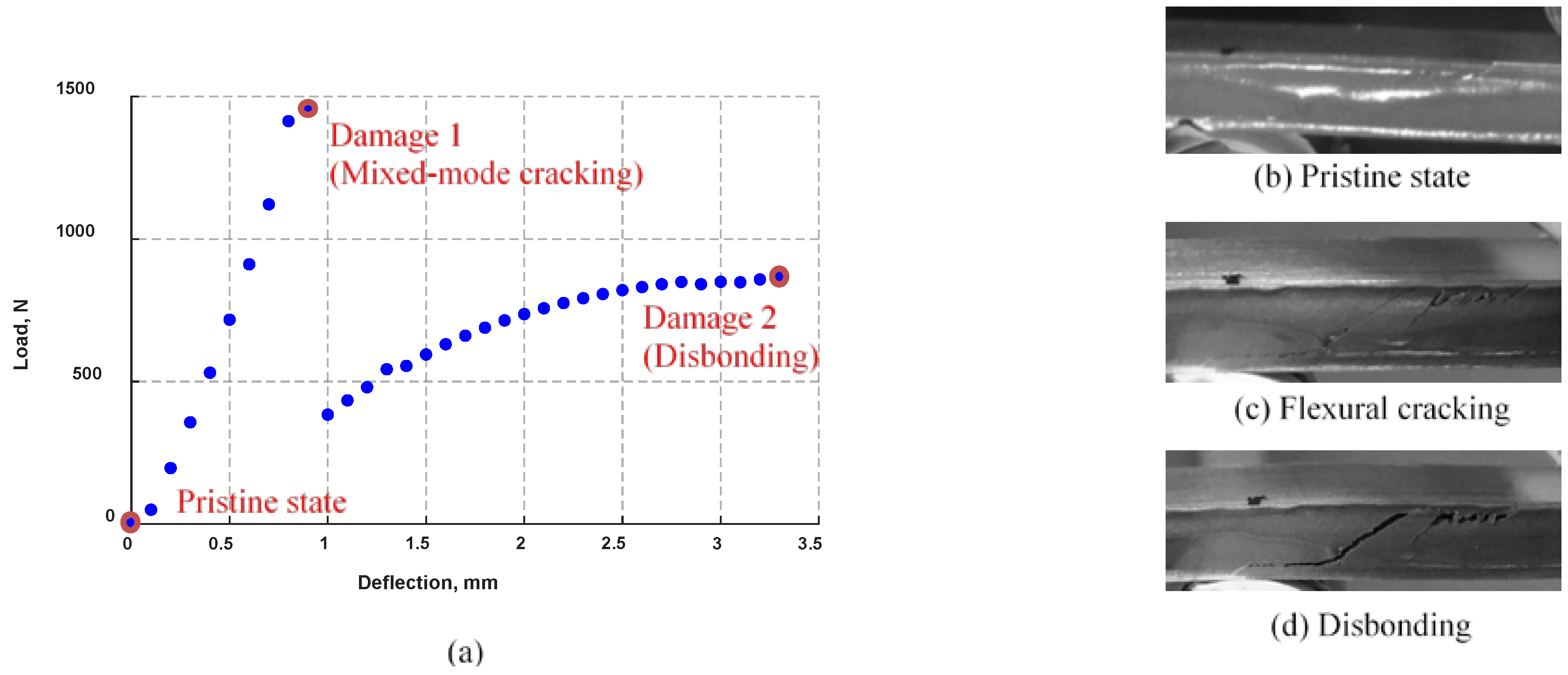
3.2. Quasi-Static Three-Point Bending

A quasi-static three-point bending test was performed cyclically on the laminate specimen to investigate the capability of bondline-embedded d15 PZTs for bondline damage detection and health monitoring of laminate structures. The experimental setup including the laminate specimen loaded in a three-point bending fixture with cylindrical rollers for the loading point and supports is shown in Figure 3. The specimen was tested in a pitch–catch configuration by actuating d15 PZT-1 and sensing with both PZT-2 and surface-mounted d31 PZT-3 sensors. The reversed path of actuation in which the waves propagate from d15 PZT-2 to d15 PZT-1 was also tested for comparison. As shown in Figure 3, the d15 PZT and d31 PZT transducers were connected to a Tektronix MDO3014 Domain Oscilloscope to collect voltage signals across the transducers at no-load condition. The d15 PZT actuator was excited with a five-peak Hann windowed signal centered at 30 kHz using a KEYSIGHT 33500B Series waveform generator connected to a Krohn-Hite 7602M Wideband Amplifier to amplify the output actuation signal.
A close-up view of the laminate specimen under three-point bending fixture is given in Figure 3 along with a schematic diagram shown in Figure 4. A quasi-static force was applied cyclically at mid-span to degrade the adhesive joint using a mechanical test machine (3369 Instron Universal Machine). The load was applied at a constant displacement rate of 1.35 mm/min (quasi-static). The displacement at mid-span was measured constantly throughout the experiment using the displacement transducer embedded in the mechanical test machine. After the load was quasi-statically applied and the mid-deflection reached a certain threshold, the load was gradually removed at the same rate. The test was then paused to obtain the electromechanical impedance response of d15 PZT transducers and to perform ultrasonic inspection. This cycle was repeated while incrementally increasing the mid-span deflection by 0.1 mm until 3.3 mm mid-span deflection was achieved. After each loading cycle, the specimen was unloaded but was not removed from the fixture to maintain accurate and consistent displacement measurements throughout the experiment.
As shown in Figure 4, the specimen was subjected to a quasi-static load at mid-span. The applied load was expected to induce bending stresses coupled to transverse shear stress in the laminate specimen. Thus, to maintain a pristine condition for the d15 PZTs and their surrounding bonding region during the test, the span between loading supports was set at 50 mm and 42.5 mm distance from the PZT transducers. Flexural rigidity was used to define the failure state of the laminate specimen and consequently to set a threshold for terminating the test. The flexural rigidity of a beam under a three-point bending configuration similar to the laminate shown in Figure 4 is given as [33]:
G f n = ( L 3 48 ) ( F n δ n )
where Gfn is the combined flexural rigidity of the laminate specimen at nth loading cycle, L is the length between loading supports, F is the mid-span load at nth loading cycle, and δ is the mid-span deflection at nth loading cycle. The stress induced in the laminate specimen can be calculated as [34]:
σ = 3 L F n 2 b h 2
where b is the width and h is the thickness of the laminate specimen. The deflection at mid-span was controlled while the applied load was measured in order to avoid high crack propagation rate and catastrophic failure of the specimen while increasing the damage severity. In this experiment, the deflection at the mid-span was increased in increments of 0.1 mm until failure while voltage measurements were captured by the PZT sensors at no-load condition.

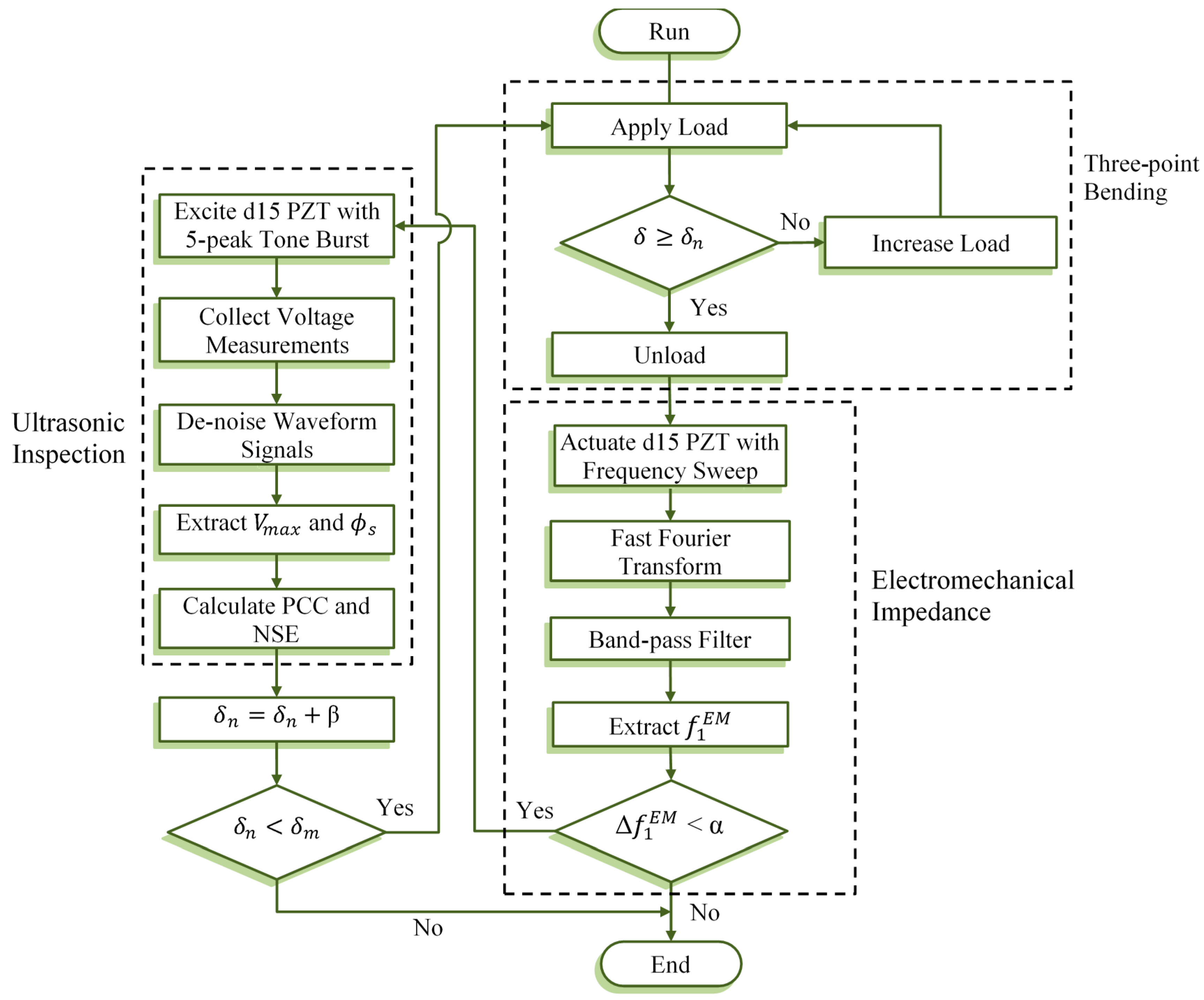
3.3. Experimental Method

Figure 5 shows a flowchart of the ultrasonic health monitoring experiment that summarizes the methodology implemented herein to investigate the ability of d15 PZTs to monitor and assess bondline integrity. The experiment consists of three major tests which are performed sequentially starting with the application of three-point bending load followed by a sine-sweep for measuring the EM impedance of d15 PZTs. The cycle ends with ultrasonic inspection using d15 PZTs in a pitch–catch orientation. The next cycle is then repeated with higher mid-span deflection, and the test continues until failure.
The health monitoring experiment was automated to sequentially perform all tests cyclically as described in the following steps:
  • Apply an increasing quasi-static load on the specimen until mid-span deflection reaches δn, then remove the applied mid-span load.
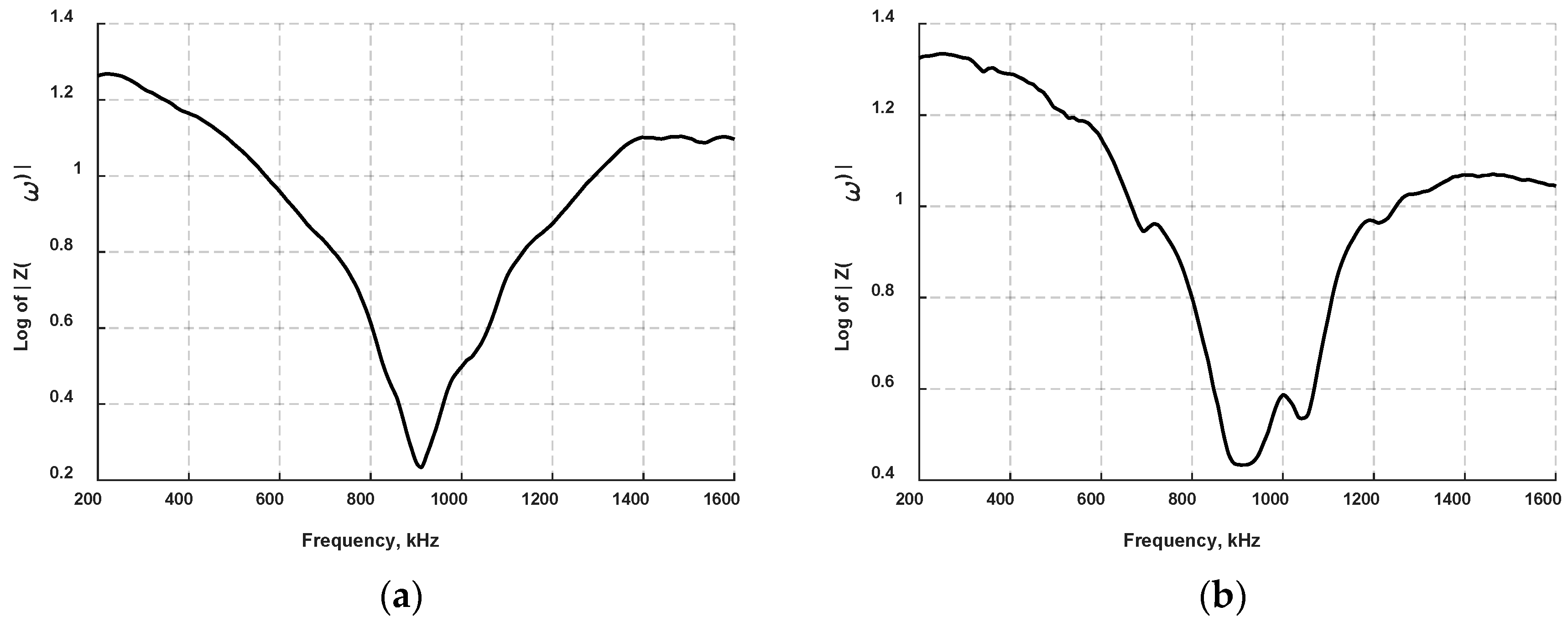
  • At no-load condition state, actuate d15 PZTs with a voltage frequency sweep (Vi) from 200 kHz to 1600 kHz by measuring the voltage (Vo) across a sensing resistor (Rs = 100 Ω) and the PZT element, then calculate the impedance, Z = R s ( V i / V o ) .
  • Apply fast Fourier transform method and band-pass filter to the harmonic signals and identify the first resonance frequency, f 1 E M , for each d15 PZT.
  • Continue the test if the difference between the baseline resonant peak and the measured resonant is less than α, which is set as 1% of the baseline resonant peak.
  • Perform ultrasonic inspection by actuating bondline-embedded d15 PZTs. The excitation signal shown in Figure 6 is a five-peak sine signal centered at 30 kHz and modulated by a Hann window, w ( n ) = 0.5 [ 1 cos ( 2 π n / N ) ] ,   0 n N , where N + 1 is the length of the window.
  • Denoise senor signals using discrete wavelet transform with Coiflet wavelet performed at level six wavelet decomposition and applying the universal threshold 2 ln ( . ) , to the wavelet coefficients.
  • Determine the maximum voltage, Vmax of the first arrival in sensor signals and the phase shift, ϕmax with respect to baseline signals.
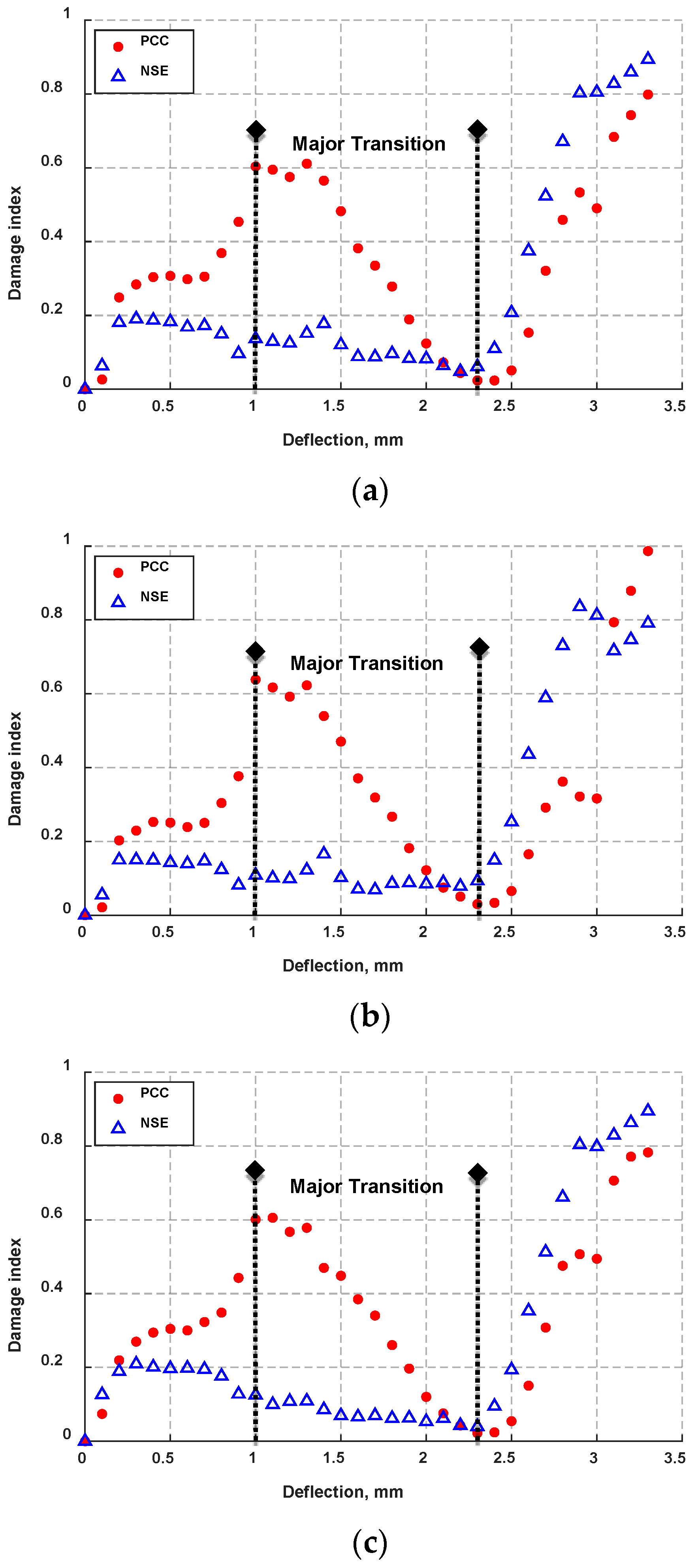
  • Calculate damage index values based on PCC and NSE methods using Equations (6) and (7), respectively.
  • Repeat loading the specimen at a higher mid-span deflection by β increment, 0.1 mm herein.
  • Stop the test when mid-span deflection reaches δm that is calculated based on flexural rigidity of the laminate specimen.
For analysis of bondline integrity, the first wave packet was selected because later waves represent reflections that are often complex superposed waves yielding higher uncertainties in the outcomes. It should be mentioned that the width of the first wave packet was identified by assuming the width of the actuation signal is close to the width of the first arrival. Despite the dispersive nature of antisymmetric waves, the dispersion effects are expected to be relatively small given the short distance between the transducers.

4. Results and Discussion

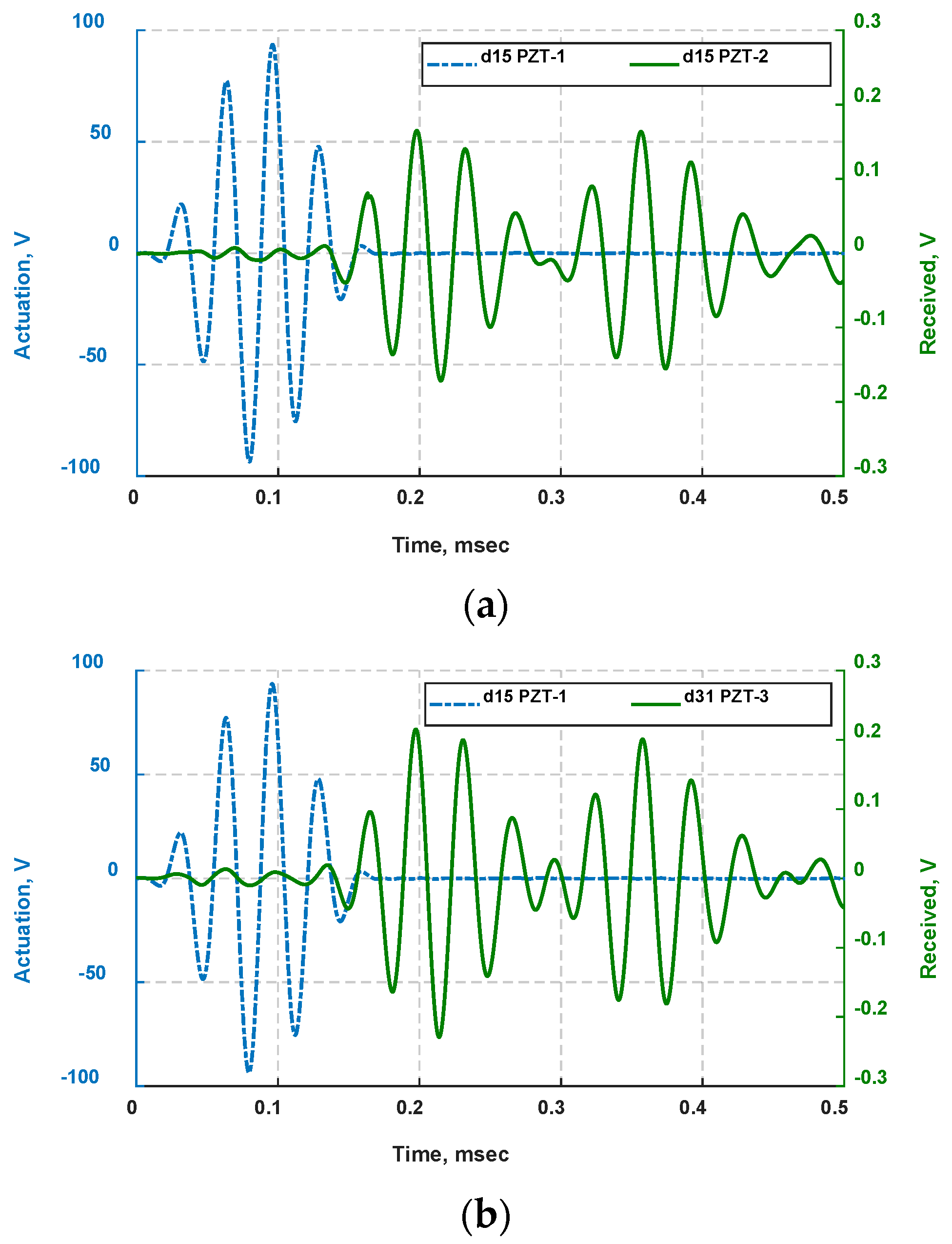
4.1. Wave Propagation Analysis

The experiment was performed at near-constant-condition temperature, pressure, and environmental conditions to mitigate environmental effects. The experiment was also performed at no-load condition to produce baseline signals that can be utilized for the analyses of damage detection in the subsequent sections.
The first propagation path (PZT-1 → PZT-2) is dictated by exciting d15 PZT-1 and sensing via d15 PZT-2 as shown in Figure 2. The same elastic waves generated by d15 PZT-1 were simultaneously also sensed by d31 PZT-3 and this propagation path is labeled as (PZT-1 → PZT-3). The opposite propagation path (PZT-2 → PZT-1) is also considered by actuating d15 PZT-2 and sensing signals with d15 PZT-1. In this experiment, a five-peak Hann windowed voltage signal centered at 30 kHz was used to actuate bondline-embedded d15 PZT piezoelectric transducers and was kept the same throughout the pitch–catch ultrasonic inspection. The signals sensed by PZTs mounted on the surface and within the bondline of the laminate specimen were recorded at a sampling rate of 10 MHz. The sensor signals are shown in Figure 6.
At 30 kHz excitation frequency, the bondline-embedded d15 PZT actuators at the neutral axis of a symmetric structure were expected to generate antisymmetric (A0) waves which are coupled with transverse shear strain with negligible other modes [25]. This finding was supported with numerical and experimental results, and discussed in more detail in [25]. As can be observed from the received signals in Figure 6, there are two main wave packets. The first wave packet travels the shortest distance directly from the actuator to the sensor. The second wave packet is a reflection from the end of the structure. Signals from both d15 PZT and d31 PZT sensors appear to have similar responses in the pristine state, but they were intrinsically generated with different dynamic mechanisms. The d15 PZT sensor signal was a result of shear strains in the x–z plane induced by the antisymmetric waves across the thickness. The shear strain is negligible at the proximity of free surfaces, nor is a d31 PZT sensitive to shear strain. The signal received by d31 PZT sensor primarily resulted from the normal strains in the x direction carrying the energy of the antisymmetric waves on the free surfaces. The time of flight (ToF) at which the A0 waves reach the sensors was determined by setting a 1% threshold of the maximum sensor voltage. The ToF and group velocity were calculated for the waveform signals received by PZT sensors and are summarized in Table 2. The ToF of d15 PZT signal sensor shown in Figure 6a is 116.6 μs with a group velocity of 1157.8 m/s. The same propagating waves were also captured simultaneously by the surface-mounted d31 PZT sensor showing slightly slower signal with a ToF of 118.2 μs due to the smaller size of d31 PZT sensor. This indicates that the same wave mode being captured by both d15 PZT and d31 PZT sensors. The small difference in ToFs captured by d15 PZT and d31 PZT sensors is attributed to different geometric and electromechanical properties among the sensors.
The reversed wave propagation (PZT-2 → PZT-1) for bondline-embedded d15 PZTs shows the antisymmetric waves have a ToF reaching the sensor at about 116.4 μs which matches well with ToFs obtained for other sensors. The variation in sensing mechanisms between surface mounted and bondline-embedded d15 PZT sensors further justifies the small difference in ToFs between d15 PZT and d31 PZT sensors.

4.2. Joint Degradation

A plot of the applied load versus deflection is shown in Figure 7. The mid-span deflection was increased from 0 to 3.3 mm in 0.1 mm increments. It can be noted from Figure 7 that the laminate specimen has an initial peak at about 1450 N indicating flexural strength of 502.1 N/mm2 at which a mixed-mode (flexural) crack developed and was located 21 mm from the applied load. The mixed-mode crack was formed at about 45 degrees plane as result of the adhesive layer between loading supports being subjected to both normal and transverse shear stresses. Residual stresses that accompany plastic deformation in localized areas such as at the applied load or at the loading supports can modulate the propagating waves in the laminate, therefore distortions in received signals prior to the flexural cracking are expected to reflect the effects of plastic deformation and joint defects.
The purpose of this test was to degrade the adhesive joint beyond the mixed-mode crack, accumulating higher level of combined damage. For this reason, the test continued past the initial peak, producing disbonds (slippage) among the laminate layers. While loading the specimen to the next cycle at 1 mm mid-deflection, a small disbond that is about 5 mm long was also observed along the bondlines. As can be noted from Figure 7c,d, the disbond initiated at the onsets of the mixed-mode crack and propagated further while increasing the mid-span deflection. In Figure 7a, the flexural rigidity of the specimen was calculated 4.1 × 10⁶ N/mm2 for the deflection range between 0–0.9 mm using Equation (8). This was followed by a significant drop in the flexural strength by more than 65%. By increasing mid-span deflection from 1 mm to 3.3 mm, its flexural rigidity significantly reduced and continuously decreased beyond 1 mm mid-deflection. Furthermore, flexural rigidity provides an indication of damage severity, particularly disbonding among the laminate layers. The three-point bending test was stopped when flexural rigidity reached almost zero.

4.3. Electromechanical Impedance

EMI method was used to inspect and ensure that no damage occurred to bondline-embedded d15 PZTs and their bonding regions during the three-point bending test. This analysis is of considerable importance, as the subsequent analyses involved the same PZT transducers for detection of joint defects. The EM impedance of bondline-embedded d15 PZT transducers were recorded after each individual cycle at no-load condition. By assuring pristine state for d15 PZTs, distortions in received signals can be mainly attributed to bondline integrity. In this analysis, the first EM frequency was monitored, therefore each d15 PZT transducer was excited with a frequency sweep from 200 kHz to 1600 kHz. The impedance responses from both transducers are shown in Figure 8. The first EM resonance was collected repeatedly after each loading cycle from bondline-embedded d15 PZTs throughout the experiment. The mean and standard deviation of the first EM resonance were calculated for d15 PZT-1 to be 912.8 kHz and 0.0194 kHz, respectively. Likewise, d15 PZT-2 has a mean of 918.8 kHz and standard deviation of 0.114 kHz. The lack of significant change in EMI response indicates that the d15 PZTs have maintained a pristine state throughout the three-point bending test.

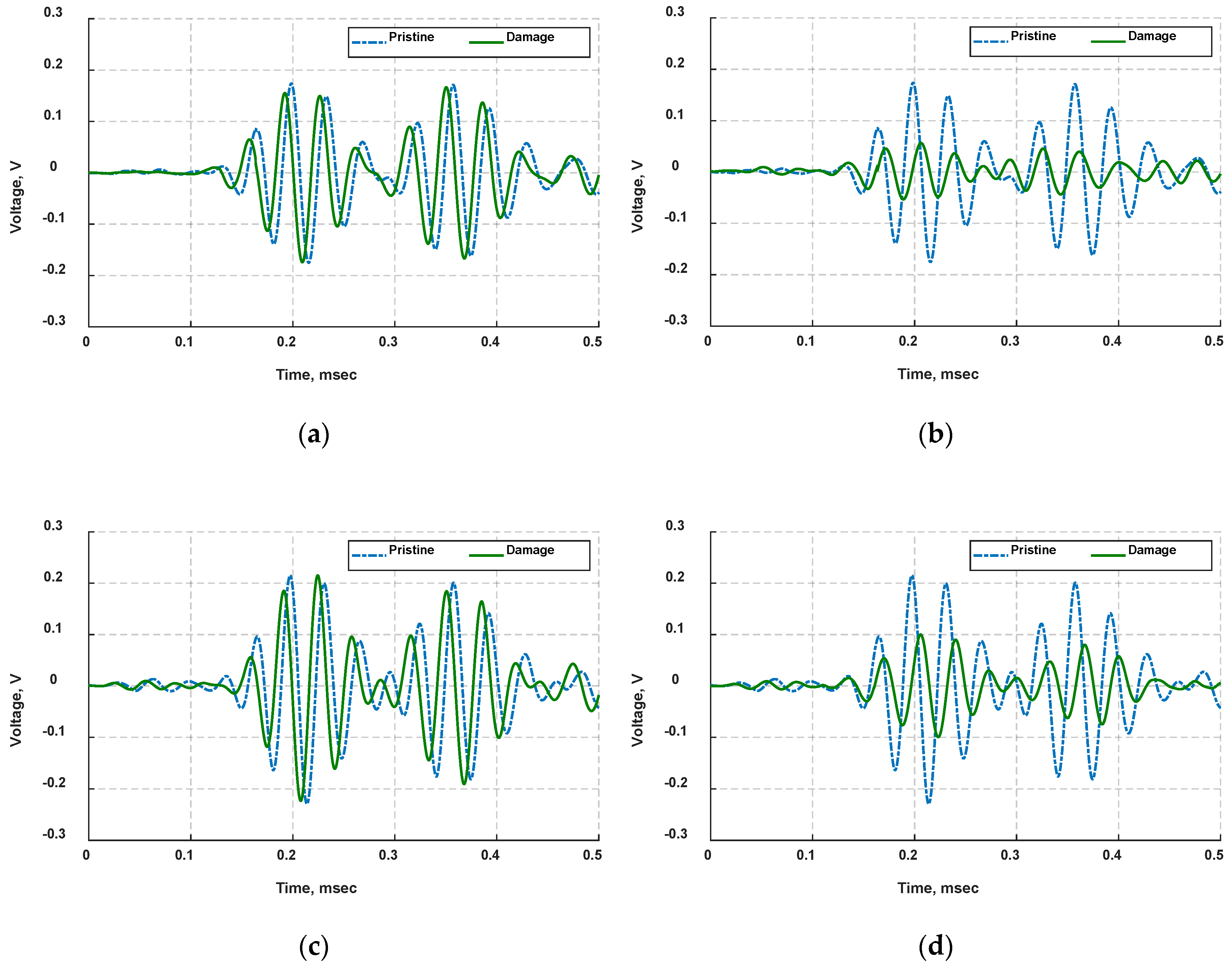
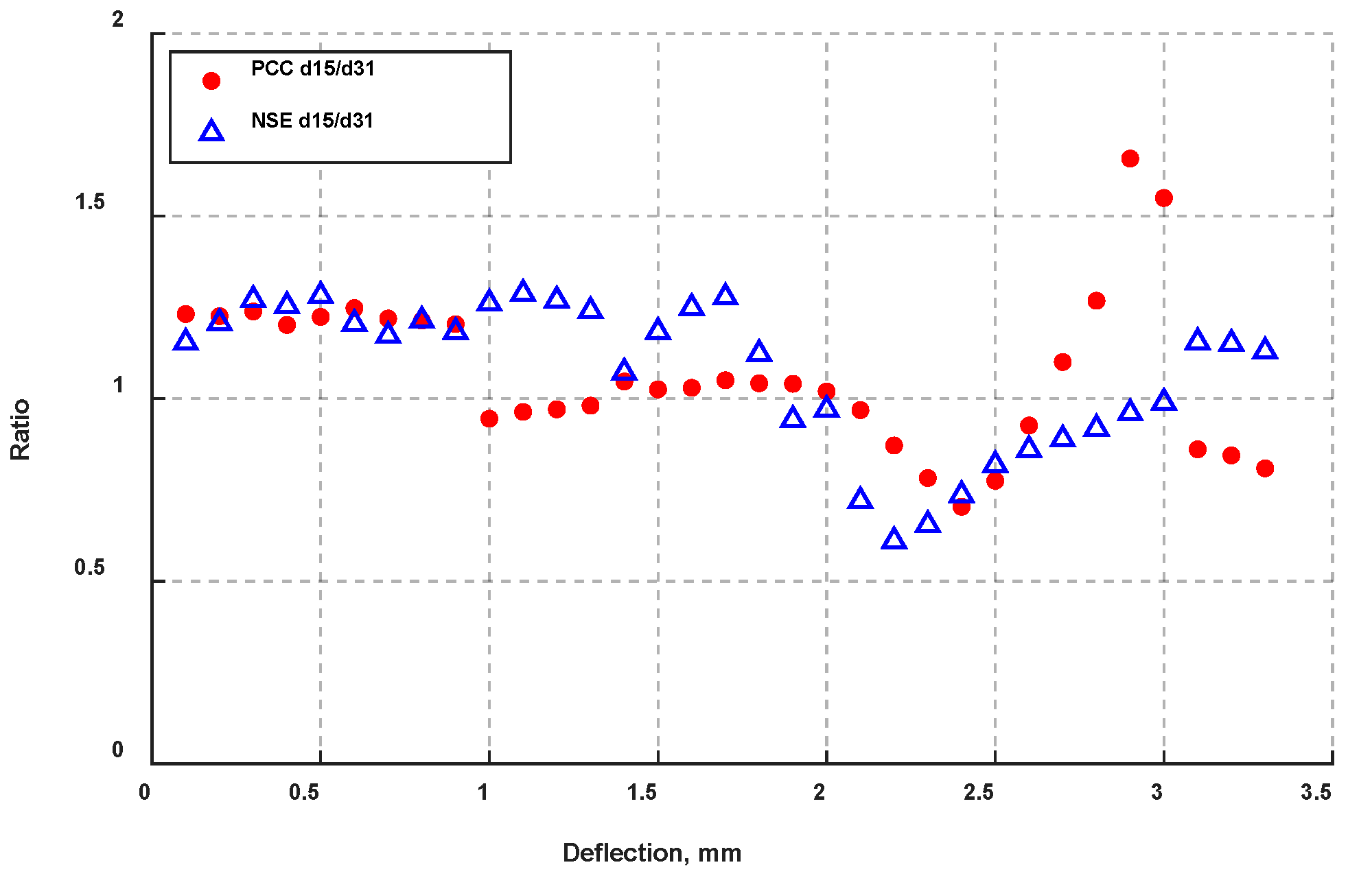
4.4. Ultrasonic Inspection

As shown in the flowchart in Figure 5, the EM impedance is followed by ultrasonic inspection in a pitch–catch scheme of actuating d15 PZT-1 with five-peak signal centered at 30 kHz and sensing voltage signals simultaneously via surface-mounted d31 PZT-3 and bondline-embedded d15 PZT-2 sensors. The same actuation signal was then used to excite d15 PZT-2 and the propagating waves were picked up by d15 PZT-1. The sensed waveforms were first de-noised using discrete wavelet transform with Coiflet mother wavelet performed at level six wavelet decomposition. After identifying the first wave packet, the maximum voltage and the phase shift with respect to baseline signals were determined for each individual cycle of mid-span deflection.
The waveform signals at 1 mm and 3.3 mm mid-span deflections were compared against the baseline signals for each corresponding PZT sensor and are given in Figure 9. The results show that the signals received at 1 mm mid-span deflection lead the baseline signals by about 60 degrees but are associated with relatively small attenuation compared to baseline signals. The signals appeared to lead the baseline signals after the initiation of mixed-mode crack along with smaller cracks, as can be seen from Figure 7c. This event may also cause a change in the thickness of the damage region yielding higher frequency-thickness product which results in slightly faster propagating waves in the laminate specimen. At 3.3 mm mid-span deflection, an opposite behavior was observed in which the recorded signals lag the baseline signals by about 80 degrees and have substantial attenuation in amplitudes. The antisymmetric waves generated by bondline-embedded d15 PZT actuators traveled through the laminate specimen governed by maximum normal strain in the x-direction on the surface and maximum xz shear strain at the neutral axis. The normal strain was mainly captured by the surface-mounted d31 PZT, while the maximum xz shear strain was sensed by bondline-embedded d15 PZTs. It can also be observed from the results in Figure 9 that the signals obtained from d15 PZT sensors show higher attenuation compared to the d31 PZT sensor signal.
Sensor waveform signals collected during the experiment were processed to determine the maximum voltage in the first arrival and the phase shift with respect to the reference signals. The results are shown in Figure 10. It can be seen from Figure 10a that the voltage amplitude displays little change until 2.3 mm deflection at which it shows a start of sharp decline in the amplitude reaching about 0.05 volts for d15 PZT-2 sensor. Over the mid-span deflection 0–3.3 mm, there is about 70% voltage reduction in the measured signals compared to the baseline signal. On the contrary, the phase shift in sensor signals (Figure 10b) has an increasing trend until 0.9 mm (prior to the mixed-mode crack) and lagging baseline signals by about 50 degrees followed by an abrupt drop by 110 degrees when cracking occurs, leading the baseline signals by 60 degrees. The increasing trend in the phase shift prior to the sharp drop at 0.9 mm mid-span deflection is attributable to the process of damage during cyclic loading developing into a flexural cracking as well as the effect of plastic deformation resulting in modulation of the propagating waves. After 0.9 mm mid-span deflection, the sensed signals show an increasing trend which crosses to the positive phase and extends past the initial peak, reaching 85 degrees at 3.3 mm deflection.
Similar trends were also observed from the signals received by the surface-mounted d31 PZT sensor as shown in Figure 10c,d. It can be observed from the results that the phase shift in d31 PZT signals also shows a significant drop at 0.9 mm mid-span deflection. The higher voltage amplitude generated by d31 PZT sensor compared to d15 PZT senor was attributed to the variation in electromechanical properties as well as differing mechanisms of sensing elements and the forces acting on these sensing elements. As previously mentioned, the normal strains induced by the d15 PZT actuator are small in the adhesive joint and maximum at the free surface, where the d31 PZT sensor was mounted. However, the shear strains are negligible at the surface and maximum at the neutral axis, where d15 PZT sensors were embedded. The surface-mounted d31 PZT sensor measured maximum normal strains while d15 PZT sensors measured the maximum shear strain in the bondline. In Figure 10e,f, similar trends were observed in which the mixed-mode crack in the bondline resulted in a significant effect on antisymmetric waves transmitted through it with negligible voltage drop.
The change in PCC and NSE damage indices calculated over the first wave packet were correlated with damage through this test. It can be observed from the results in Figure 11 that PCC increases as the deflection increases until reaching an initial peak at about 0.9 mm at which the mixed-mode crack was fully developed in the specimen. The increasing trend of PCC before the mixed-mode cracking can also be attributed to the progressive damage in a form of small defects and plastic deformation in the region between the loading supports. This was followed by a decreasing trend in the damage index value reaching a local low at 2.3 mm. That was next followed by increasing trends reaching the maximum index value at 3.3 mm deflection. This behavior was observed from all embedded sensors in the specimen. The NSE damage index is less sensitive to phase shift in the signals and exhibits constantly decreasing trend from 0–2.3 mm deflection suggesting that the change in energy of the received signals is relatively small. This behavior reversed to an upward trend indicating a significant drop in the signal energy reaching its maximum at 3.3 mm mid-span deflection. This behavior can be observed from d15 PZT sensors as well as d31 PZT sensor with minor variation.
The damage index ratios of d15 PZT to d31 PZT for PCC and NSE were calculated to compare the sensitivity of both sensors. The results are displaced in Figure 12. A ratio value of one indicates both sensors have the same sensitivity whereas a ratio value greater than one indicates d15 PZT sensor has higher sensitivity than d31 PZT sensor, and vice versa. It can be observed from Figure 12 that the majority of PCC and NSE ratios show values above unity. This can be attributed to the optimal location advantage of d15 PZTs being internally embedded within the adhesive layer, resulting in direct coupling to the bondline.
The damage index values of PCC in Figure 11 reveals the interaction level of antisymmetric waves with the damage. It can be noted from Figure 11, despite the increase in damage severity of the laminate specimen, the values of NSE and PCE show decreasing behavior until loading cycle reached 2.3 mm. This trend could be due to the change in damage characteristics resulting in low interaction between the antisymmetric waves and the bondline damage. Antisymmetric waves tend to interact much less with linear defects, such as voids, than with nonlinear defects such as disbonds and cracks. The high sensitivity of antisymmetric waves to nonlinear defects is often attributed to the change in the contact length of a defect during the propagation of waves [35,36,37]. Therefore, when the mixed-mode crack initiated over the mid-span deflection 0–0.9 mm, the crack has the characteristics of a nonlinear defect that has strong interaction with antisymmetric waves. Thus, the PCC damage index from all sensors shows an increasing trend until the mixed-mode crack fully developed at 0.9 mm mid-span deflection. The decreasing trend beyond 0.9 mm suggests the damage evolution was not favorable to antisymmetric waves and reached its maximum growth at 2.3 mm deflection. Higher deflection exacerbated the level of damage; both damage indices predicted low values suggesting antisymmetric waves have minimal interaction with damage at 2.3 mm mid-span deflection. Over the deflection range 1–2.3 mm, the laminate specimen is expected to be accompanied by plastic deformation causing the mixed-mode crack to gradually develop into a large void such that the crack remains open at no-load conditions resulting in less interaction with antisymmetric waves.
Despite the presence of disbonds at the early stage over 1–2.3 mm mid-span deflection range, it is expected the contribution of disbonds to voltage waveform distortion is minimal as the results suggest that disbonds were either zero-volume disbonds or were comparatively not long enough to interact with 36-mm-wavelength antisymmetric waves. The damage index values from both NSE and PCC reveal a turning point at 2.3 mm with a sharp upward trend until failure. It was noted that the flexural rigidity of the specimen constantly decreased while the disbond grew, resulting in longer disbonds which were expected to be the main source for the noticeable distortion in the received waveform signals over the mid-span deflection range 2.3–3.3 mm. This finding agrees well with state-of-the-art ultrasonic wave interaction with defects supporting that elastic waves including antisymmetric waves have higher sensitivity to nonlinear defects such as cracks and disbonds than linear defects such as voids [35,36,37,38].
The PCC damage index is more sensitive to phase shift while the NSE damage index is more sensitive to amplitude of voltage waveform signals as reflected in Figure 10 and Figure 11. Despite the existence of a combined defect in the bondline, the amount of distortion inflicted on the propagating antisymmetric waves is determined by the dominant type of defect. In this study, the defect type was not controlled thus multiple joint defects were present simultaneously. This presented a challenge to correlate change in waveform signals with a certain type of defect.

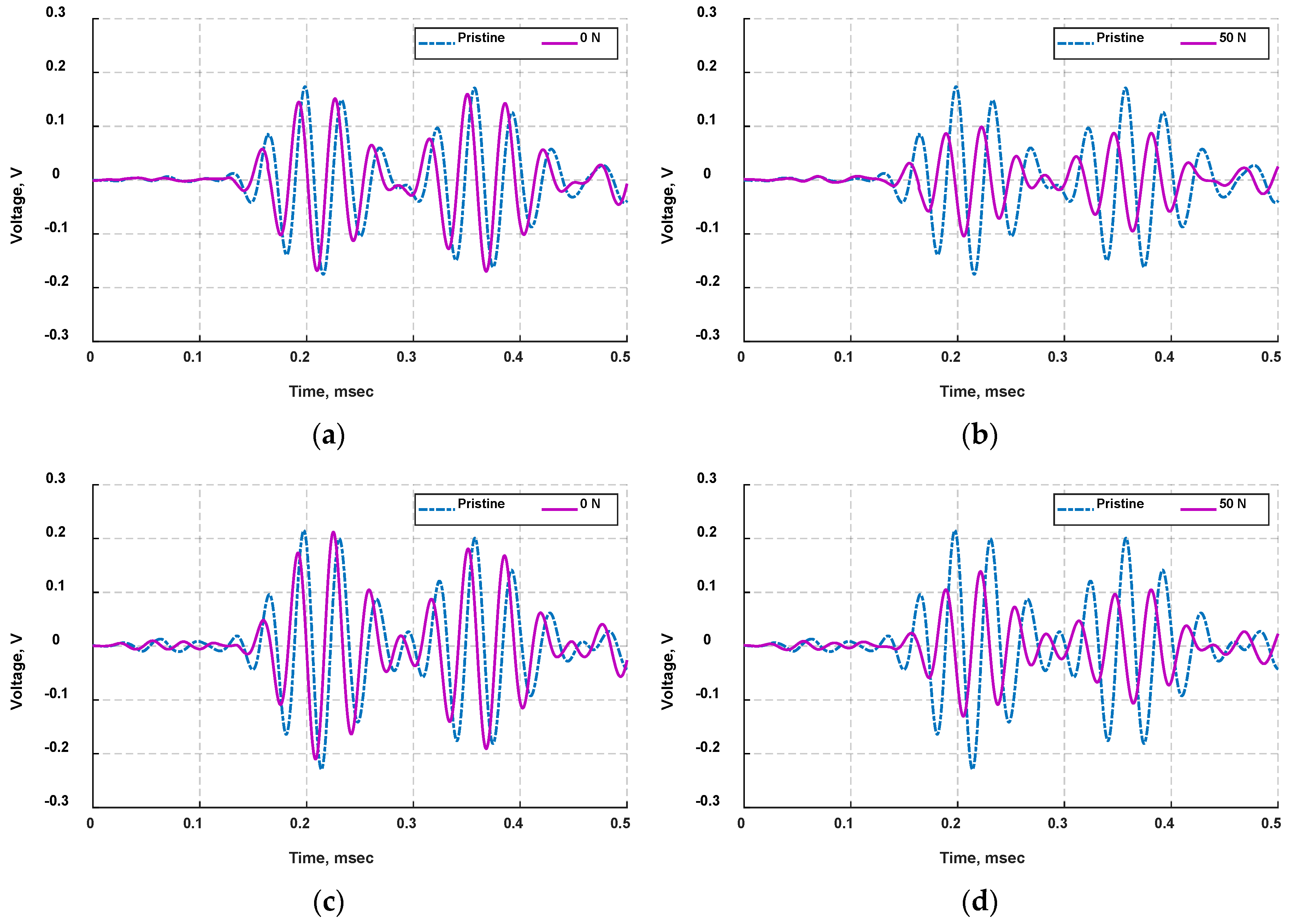
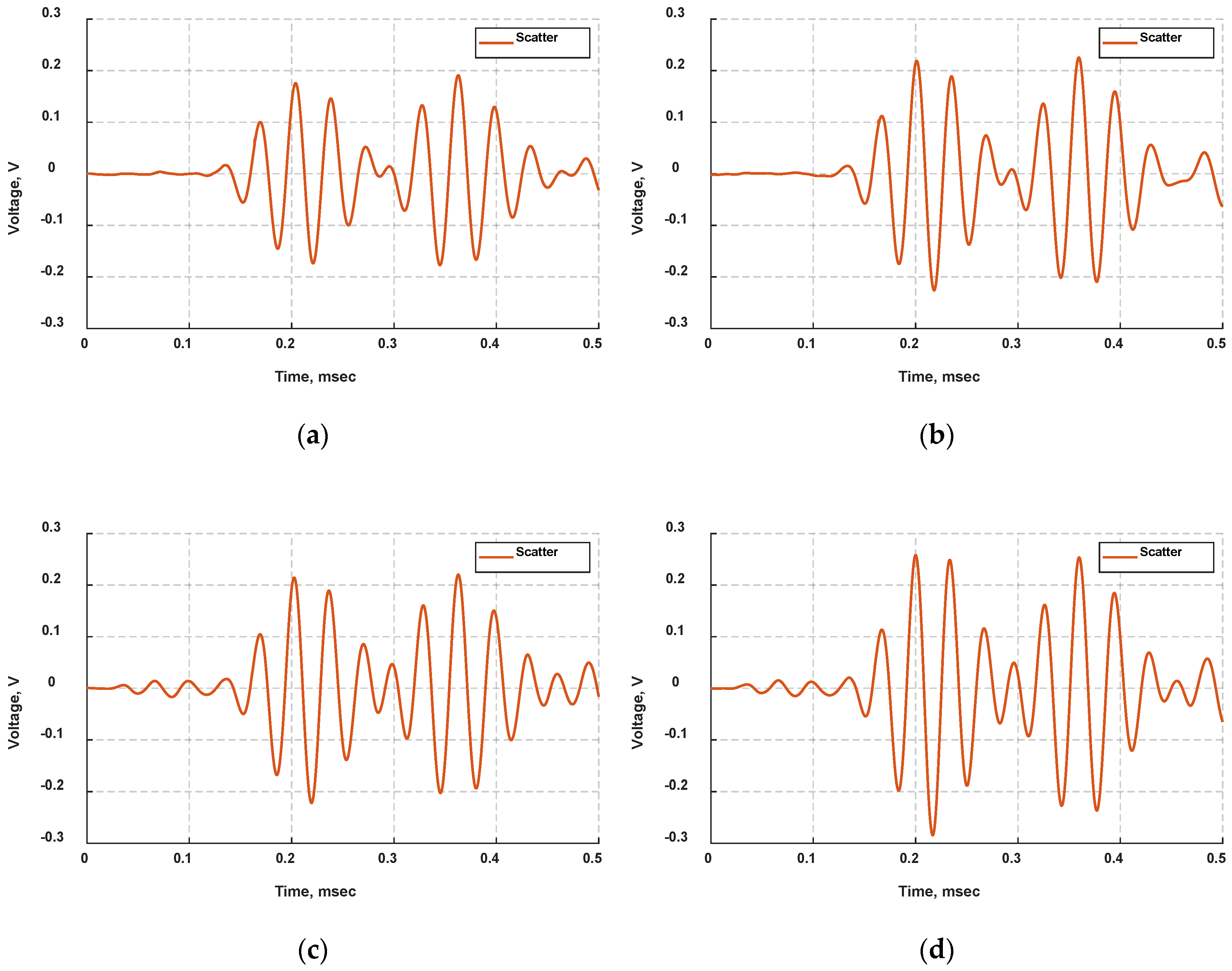
4.5. Influence of Preload Condition

This test was performed after the mixed-mode crack initiated in the same laminate specimen used in this experiment. In this analysis, actuation of bondline-embedded d15 PZTs and the sensing of elastic waves in the laminate specimen has occurred at a preload condition such that the mid-span load was not fully removed during ultrasonic inspection. An application of a small load on the specimen is expected to alter the characteristics of the combined defects and consequently the propagation of ultrasonic waves.
The waveform signals picked up by the bondline-embedded d15 PZT and the surface-mounted d31 PZT for the three-point bending cycle of 1.3 mm mid-span deflection at no-preload condition are presented in Figure 13. The received signals were superimposed with baseline signals for comparison purposes, and the scattered signals which are the difference between the measured signals and the baseline signals were also calculated and displayed in Figure 14. The received and scattered signals when a 50 N force was applied are shown in Figure 13 and Figure 14. Despite the small magnitude of the applied load, the mid-span deflection was about 0.18 mm due to the preexisting damage in the specimen. Therefore, the analysis indicates a significant difference between received signals from preload condition and no-preload condition. It can be noted from Figure 13 and Figure 14 that the captured signals at preload condition are lagging the baseline signals with significant phase shift and voltage reduction as compared with received signals at no-preload condition. The damage indices based on PCC and NSE methods were also calculated for both loading conditions with results given in Table 3. The damage index values indicate that the damage exists with high severity at 1.3 mm mid-span deflection. Using Equation (9), the amount of stress induced by the applied load was estimated to be about 17 N/mm2. The applied load at mid-span produces normal stresses across the thickness between loading supports, thus the propagating waves are anticipated to be modulated and be reflected on the received signals. However, this resulting distortion from a small applied load is expected to have negligible effect as compared to the effect of damage on the propagating waves. The results strongly suggest that the applied load on the specimen caused a geometric change to the bondline damage resulting in significant distortion to the propagating waves. As previously discussed in Section 4.4, the mixed-mode crack was observed and fully developed in the bondline at 0.9 mm mid-span deflection, and that was followed by plastic deformation causing the crack to remain open resulting in low distortion in received signals over the range 1–2.3 mm mid-span deflection as shown in Figure 11. Therefore, in the preload condition at 1.3 mm mid-span deflection, the applied load is anticipated to open the mixed-mode crack and disbonds while the antisymmetric waves transmitted through the bondline cause higher scattering of the propagating waves.
The results in Table 3 indicate that the damage index values calculated for bondline-embedded d15 PZT sensor are consistently higher than the surface-mounted d31 PZT sensor in both preload conditions. As mentioned in earlier literature [4,5], ultrasonic waves that put the bondline in shear interact profoundly with nonlinear defects; this study supports this finding as well. It is worth mentioning that the presented damage detection methodology has two obvious issues concerning its applications in real-life structures: (a) Embedding PZT sensors in bondlines of laminate structures could potentially weaken the bond strength and make it susceptible to defects. (b) The tested adhesive layer is considered too thick and often not desirable. Potential methods to address this are mentioned in the future work section and could include miniaturized sensing elements which have been developed already and are used to monitor various structures [39,40]. The development and evaluation of embedding sensing elements inside the bondline of laminate structures for structural integrity assessment using piezoelectric transducers has shown promising results and is still under investigation [2,3,41]. Furthermore, despite differing sensitivity of antisymmetric waves to the inflicted damage, bondline-embedded d15 PZTs provide a promising initial step forward for health monitoring of bondline integrity.

5. Conclusions

This paper presented an investigation into bondline damage detection employing d15 piezoelectric transducers that were embedded within the bondline of a laminate structure. Two methods were implemented in this experiment to assess the ability of d15 PZT transducers to monitor adhesive joint integrity: (1) ultrasonic wave propagation method to inspect the regions between the sensors and (2) EMI method to inspect the regions at the location of sensors using its inherent sensitivity to structural stiffness. An aluminum–epoxy–aluminum specimen consisting of surface-mounted d31 PZT and bondline-embedded d15 PZT transducers was carefully designed to test sensitivity to joint defects. The joint defects in the bondline were created by quasi-static three-point bending test, and electromechanical impedance of d15 PZTs was measured after each three-point loading cycle to ensure they did not incur damage throughout the experiment. A five-peak tone burst signal centered at 30 kHz was used throughout the experiment to excite bondline-embedded d15 PZTs to generate antisymmetric waves in the laminate specimen. It was observed that antisymmetric waves generated by d15 PZT actuators exhibited strong interaction with joint defects, especially nonlinear defects such as cracks and disbonds, supporting the capability of the proposed methodology for ultrasonic inspection of adhesively bonded structures. It was observed from experimental results that d15 PZT sensors consistently showed larger changes in voltage amplitude due to bondline defects when compared to the signals produced by the surface-mounted d31 PZT sensor. This was due to a combination of the location advantage of d15 PZT sensor being in the bondline sensing shear strain, and the different electromechanical coupling properties. Two damage indices based on Pearson correlation coefficient and normalized signal energy were investigated to detect the presence of damage and its severity. It was found that Pearson correlation coefficient is more sensitive to phase shift in received signals while normalized signal energy method more sensitive to amplitude of voltage waveform signals. The proposed approach provides novel insights into the benefits offered by bondline-embedded d15 PZT transducers for the health monitoring of adhesive bond joints.

6. Future Work

This work represents a large-scale investigation of the feasibility of a novel approach using shear-mode PZTs for damage detection. The use of three-point bending test introduced different types of defects and plastic deformation in the specimen. The effects of plasticity and different types of defects presented a challenge to clearly distinguish distortions in propagating waves caused by defects from the ones resulting from plastic deformation. Further investigation is necessary to fully understand the capabilities and drawbacks of midline shear actuation and sensing for damage detection. Miniaturization of the system is also necessary to make shear-mode PZTs embeddable in realistic bondlines with a goal of reducing the size of components to that of a scrim of adhesive films. Optimizing design and miniaturization of shear-mode piezoelectric transducers are of considerable interest to accelerate their integration into ultrasonic structural health monitoring systems. Furthermore, this work was limited to a specific actuation frequency throughout the ultrasonic inspection test, thus further investigation concerning the relation between actuation frequency and sensitivity of waves to joint defects needs to be considered. Employing more sophisticated signal extraction methods could improve damage detection capabilities, identifying the characteristics of existing defects, their severity, and the remaining useful life of a structure.

Author Contributions

Conceptualization, H.A. and N.S.; Methodology, H.A. and N.S.; Experiments and data analysis, H.A., Writing—original draft preparation, H.A.; Writing—review and editing, H.A., N.S. and A.D.; Supervision, N.S. and A.D.; Funding acquisition, N.S.

Funding

This work was supported in part by funding from University of Wisconsin—Milwaukee.

Conflicts of Interest

The authors declare no conflict of interest.

References

  1. Structural Integrity and Durability of Advanced Composites: Innovative Modelling Methods and Intelligent Design; Beaumont, P.W.R.; Soutis, C.; Hodzic, A. (Eds.) Woodhead Publishing: Sawston, UK; Cambridge, UK, 2015; ISBN 978-0-08-100137-0. [Google Scholar]
  2. Dugnani, R.; Zhuang, Y.; Kopsaftopoulos, F.; Chang, F.-K. Adhesive bond-line degradation detection via a cross-correlation electromechanical impedance–based approach. Struct. Health Monit. 2016, 15, 650–667. [Google Scholar] [CrossRef]
  3. Zhuang, Y.; Li, Y.-H.; Kopsaftopoulos, F.; Chang, F.-K. A self-diagnostic adhesive for monitoring bonded joints in aerospace structures. In Proceedings of the Sensors and Smart Structures Technologies for Civil, Mechanical, and Aerospace Systems, Las Vegas, NV, USA, 20 April 2016. [Google Scholar]
  4. Nagy, P.B. Ultrasonic detection of kissing bonds at adhesive interfaces. J. Adhes. Sci. Technol. 1991, 5, 619–630. [Google Scholar] [CrossRef]
  5. Kundu, T.; Maji, A.; Ghosh, T.; Maslov, K. Detection of kissing bonds by Lamb waves. Ultrasonics 1998, 35, 573–580. [Google Scholar] [CrossRef]
  6. Ramadas, C.; Balasubramaniam, K.; Joshi, M.; Krishnamurthy, C.V. Numerical and experimental studies on propagation of A0mode in a composite plate containing semi-infinite delamination: Observation of turning modes. Compos. Struct. 2011, 93, 1929–1938. [Google Scholar] [CrossRef]
  7. Masserey, B.; Raemy, C.; Fromme, P. High-frequency guided ultrasonic waves for hidden defect detection in multi-layered aircraft structures. Ultrasonics 2014, 54, 1720–1728. [Google Scholar] [CrossRef] [PubMed] [Green Version]
  8. Zhang, K.; Zhou, Z. Quantitative characterization of disbonds in multilayered bonded composites using laser ultrasonic guided waves. NDT E Int. 2018, 97, 42–50. [Google Scholar] [CrossRef]
  9. Guo, N.; Cawley, P. Lamb wave propagation in composite laminates and its relationship with acousto-ultrasonics. NDT E Int. 1993, 26, 75–84. [Google Scholar] [CrossRef]
  10. Ramadas, C.; Balasubramaniam, K.; Joshi, M.; Krishnamurthy, C.V. Characterisation of rectangular type delaminations in composite laminates through B- and D-scan images generated using Lamb waves. NDT E Int. 2011, 44, 281–289. [Google Scholar] [CrossRef]
  11. Altammar, H.; Kaul, S.; Dhingra, A.K. Use of wavelets for damage diagnostics in truss structures. Int. J. Struct. Integr. 2017, 8, 373–391. [Google Scholar] [CrossRef]
  12. Mix, P.E. Introduction to Nondestructive Testing: A Training Guide; John Wiley & Sons: Hoboken, NJ, USA, 2005; ISBN 13 978-0-471-42029-3. [Google Scholar]
  13. Hellier, C.J. Handbook of Nondestructive Evaluation; McGraw-Hill Education: New York, NY, USA, 2012; Volume 69, ISBN 007139947X. [Google Scholar]
  14. Gulizzi, V.; Rizzo, P.; Milazzo, A. Electromechanical impedance method for the health monitoring of bonded joints: Numerical modelling and experimental validation. SDHM Struct. Durab. Health Monit. 2014, 10, 19–54. [Google Scholar]
  15. Malinowski, P.; Wandowski, T.; Ostachowicz, W. The use of electromechanical impedance conductance signatures for detection of weak adhesive bonds of carbon fibre–reinforced polymer. Struct. Health Monit. 2015, 14, 332–344. [Google Scholar] [CrossRef]
  16. Altammar, H.; Dhingra, A.; Salowitz, N. Initial study of internally embedded shear-mode piezoelectric transducers for the detection of joint defects in laminate structures. J. Intell. Mater. Syst. Struct. 2019, 30, 2314–2330. [Google Scholar] [CrossRef]
  17. Dı́az Valdés, S.H.; Soutis, C.; Dı́az Valdés, S.H.; Soutis, C.; Diaz Vald, S.H.; Soutis, C. Real-time nondestructive evaluation of fiber composite laminates using low-frequency Lamb waves. J. Acoust. Soc. Am. 2002, 111, 2026–2033. [Google Scholar] [CrossRef] [PubMed]
  18. Osmont, D.; Devillers, D.; Taillade, F. Health Monitoring of Sandwich Plates Based on the Analysis of the Interaction of Lamb Waves with Damages. Smart Struct. Integr. Syst. 2001, 4327, 290–301. [Google Scholar]
  19. Wilcox, P.D.; Lee, C.K.; Scholey, J.J.; Friswell, M.I.; Wisnom, M.R.; Drinkwater, B.W. Quantitative structural health monitoring using acoustic emission. SPIE Conf. Proc. 2006, 6173, 61731K. [Google Scholar]
  20. Pau, A.; Achillopoulou, D.V.; Vestroni, F. Scattering of guided shear waves in plates with discontinuities. NDT E Int. 2016, 84, 67–75. [Google Scholar] [CrossRef]
  21. Kamal, A.; Giurgiutiu, V. Shear horizontal wave excitation and reception with shear horizontal piezoelectric wafer active sensor (SH-PWAS). Smart Mater. Struct. 2014, 23, 085019. [Google Scholar] [CrossRef]
  22. Zhou, W.; Li, H.; Yuan, F.G. Guided wave generation, sensing and damage detection using in-plane shear piezoelectric wafers. Smart Mater. Struct. 2013, 23, 015014. [Google Scholar] [CrossRef]
  23. Hou, S.; Zhang, H.B.; Ou, J.P. A PZT-based smart aggregate for seismic shear stress monitoring. Smart Mater. Struct. 2013, 22, 065012. [Google Scholar] [CrossRef]
  24. Zhou, W.; Li, H.; Yuan, F.G. Fundamental understanding of wave generation and reception using d36 type piezoelectric transducers. Ultrasonics 2015, 57, 135–143. [Google Scholar] [CrossRef] [PubMed]
  25. Altammar, H.; Dhingra, A.; Salowitz, N. Ultrasonic Sensing and Actuation in Laminate Structures Using Bondline-Embedded d35 Piezoelectric Sensors. Sensors 2018, 18, 21. [Google Scholar] [CrossRef] [PubMed]
  26. Köhler, B.; Gaul, T.; Lieske, U.; Schubert, F. Shear horizontal piezoelectric fiber patch transducers (SH-PFP) for guided elastic wave applications. NDT E Int. 2016, 82, 1–12. [Google Scholar] [CrossRef]
  27. APC International, Ltd. Piezoelectric Ceramics: Principles and Applications, 1st ed.; APC International: Mackeyville, PA, USA, 2002; ISBN 0615565034. [Google Scholar]
  28. IEEE Standard on Piezoelectricity “ANSI/IEEE Std 176-1987”; The Institute of Electrical and Electronics Engineers Inc.: Piscataway, NJ, USA, 1988; Volume 74.
  29. Giurgiutiu, V. Structural Health Monitoring With Piezoelectric Wafer Active Sensors, 2nd ed.; Elsevier Inc.: London, UK, 2014; ISBN 9780124186910. [Google Scholar]
  30. Wu, Z.; Qing, X.P.; Ghosh, K.; Karbhari, V.M.; Chang, F.-K. Health monitoring of bonded composite repair in bridge rehabilitation. Smart Mater. Struct. 2008, 17, 045014. [Google Scholar] [CrossRef]
  31. Torkamani, S.; Roy, S.; Barkey, M.E.; Sazonov, E.; Burkett, S.; Kotru, S. A novel damage index for damage identification using guided waves with application in laminated composites. Smart Mater. Struct. 2014, 23, 095015. [Google Scholar] [CrossRef]
  32. Tseng, K.K.-H.; Naidu, A.S.K. Non-parametric damage detection and characterization using smart piezoceramic material. Smart Mater. Struct. 2002, 11, 317–329. [Google Scholar] [CrossRef]
  33. Methods, S.T. ASTM E 290—Standard Test Methods for Bend Testing of Material for Ductility. Current 1998, 3, 1–10. [Google Scholar]
  34. Dowling, N.E. Mechanical Behavior of Materials, 4th ed.; Pearson Education, Inc.: Hoboken, NJ, USA, 2013; ISBN 9780131395060. [Google Scholar]
  35. Broda, D.; Staszewski, W.J.; Martowicz, A.; Uhl, T.; Silberschmidt, V.V. Modelling of nonlinear crack–wave interactions for damage detection based on ultrasound—A review. J. Sound Vib. 2014, 333, 1097–1118. [Google Scholar] [CrossRef]
  36. Alleyne, D.N.; Cawley, P. The Interaction of Lamb Waves with Defects. IEEE Trans. Ultrason. Ferroelectr. Freq. Control 1992, 39, 381–397. [Google Scholar] [CrossRef] [PubMed]
  37. Greve, D.W.; Tyson, N.; Oppenheim, I.J. Interaction of defects with Lamb waves in complex geometries. Proc. IEEE Ultrason. Symp. 2005, 1, 297–300. [Google Scholar]
  38. Altammar, H.; Dhingra, A.; Salowitz, N. Investigating the Feasibility of Ultrasonic Shear Actuation for Evaluation of Adhesive Joints in Multilayered Structures: FE Simulation. In Proceedings of the ASNT Annual Conference, Nashville, Tennessee, 30 October–2 November 2017; pp. 25–34. [Google Scholar]
  39. Salowitz, N.P.; Guo, Z.; Kim, S.J.; Li, Y.H.; Lanzara, G.; Chang, F.K. Microfabricated expandable sensor networks for intelligent sensing materials. IEEE Sens. J. 2014, 14, 2138–2144. [Google Scholar] [CrossRef]
  40. Salowitz, N.; Guo, Z.; Li, Y.H.; Kim, K.; Lanzara, G.; Chang, F.K. Bio-inspired stretchable network-based intelligent composites. J. Compos. Mater. 2013, 47, 97–105. [Google Scholar] [CrossRef]
  41. Chalioris, C.E.; Papadopoulos, N.A.; Angeli, G.M.; Karayannis, C.G.; Liolios, A.A.; Providakis, C.P. Damage Evaluation in Shear-Critical Reinforced Concrete Beam using Piezoelectric Transducers as Smart Aggregates. Open Eng. 2015, 5, 373–384. [Google Scholar] [CrossRef]
Figure 1. Schematic of a d15 piezoelectric transducer with fundamental wave modes depicted in the direction of wave propagation.
Actuators 08 00070 g001
Figure 2. Schematic diagram of laminate specimen with two d15 lead zirconate titanate (PZT) transducers (15 mm × 15 mm × 1 mm) embedded in the bondline and d31 PZT sensor (6 mm × 0.25 mm) mounted on the surface of the bottom aluminum sheet.
Actuators 08 00070 g002
Figure 3. Experimental setup of health monitoring experiment and magnified view of laminate specimen under three-point bending test.
Actuators 08 00070 g003
Figure 4. Laminate specimen under a quasi-static three-point bending force applied cyclically at mid-span.
Actuators 08 00070 g004
Figure 5. Flowchart of ultrasonic health monitoring experiment for a laminate specimen with surface-mounted and bondline-embedded PZT transducers.
Actuators 08 00070 g005
Figure 6. Waveform signals obtained from laminate specimen with d31 PZT and d15 PZT transducers for wave propagation paths: (a) PZT-1 → PZT-2 and (b) PZT-1 → PZT-3.
Actuators 08 00070 g006
Figure 7. (a) Load–deflection response of laminate specimen under three-point bending test at: (b) pristine state; (c) flexural cracking at 0.9 mm mid-span deflection; and (d) disbonding at 3.3 mm mid-span deflection.
Actuators 08 00070 g007
Figure 8. Electromechanical impedance (EMI) response of bondline-embedded d15 PZTs at the pristine state with a frequency range containing the first EM resonance for: (a) d15 PZT-1 and (b) d15 PZT-2.
Actuators 08 00070 g008
Figure 9. Comparison of waveform signals collected from bondline-embedded d15 PZT and surface mounted d31 PZT sensors at 1 mm deflection (left column) and 3.3 mm deflection (right column) for wave propagation paths: (a,b) PZT-1 → PZT-2 and (c,d) PZT-1 → PZT-3.
Actuators 08 00070 g009
Figure 10. Maximum voltage amplitude (left column) and phase shift (right column) from waveform signals collected from bondline-embedded d15 PZT and surface mounted d31 PZT sensors for wave propagation paths: (a,b) PZT-1 → PZT-2; (c,d) PZT-1 → PZT-3; and (e,f) PZT-2 → PZT-1.
Actuators 08 00070 g010
Figure 11. Damage index values based on Pearson correlation coefficient (PCC) and normalized signal energy (NSE) methods calculated for the first arrival of sensor signals received by: (a) d15 PZT-2; (b) d31 PZT-3; and (c) d15 PZT-1.
Actuators 08 00070 g011
Figure 12. Damage index ratios of d15 PZT to d31 PZT for PCC and NSE.
Actuators 08 00070 g012
Figure 13. Comparison of voltage signals from laminate specimen at no-preload condition (left column) and 50 N mid-span preload (right column) at 1.3 mm three-point loading cycle: (a,b) d15 PZT-2 sensor and (c,d) d31 PZT-3 sensor.
Actuators 08 00070 g013
Figure 14. Scattered signals from laminate specimen at no-preload condition (left column) and 50 N mid-span preload (right column) at 1.3 mm three-point loading cycle: (a,b) d15 PZT-2 sensor and (c,d) d31 PZT-3 sensor.
Actuators 08 00070 g014
Table 1. Material properties of the shear-mode piezoelectric transducer, Hysol EA9394, and Aluminum 6061 [16].
PropertyUnitSymbolPZT-5AAdhesiveAluminum
Young’s Modulus109 N/m2Y1161.04.2468.9
109 N/m2Y3353.24.2468.9
Shear’s Modulus109 N/m2G1222.61.4625.9
109 N/m2G1310.51.4625.9
Poisson’s ratio1v120.350.450.33
1v130.440.450.33
Densitykg/m3ρ760013602700
Dielectric permittivity8.854 µF/mε111851------------
8.854 µF/mε131581------------
Piezoelectric coefficient10−12 m/Vd15584------------
10−12 m/Vd31−171------------
10−12 m/Vd33374------------
Table 2. Summary of wave propagation results including time of flight (ToF) and group velocity for waveform signals from bondline-embedded d15 and surface-mounted d31 PZT sensors at no-load condition.
Wave Propagation PathTime of Flight (μs)Group Velocity (m/s)
PZT-1 → PZT-2116.61157.8
PZT-1 → PZT-3118.11143.1
PZT-2 → PZT-1116.41159.8
Table 3. Damage indices of PCC and NSE for signals obtained from d15 PZT-2 and d31 PZT-3 at 0 N (no-preload condition) and at 50 N preload applied on the specimen at 1.3 mm three-point loading cycle.
Wave Propagation Path0 N50 N
PCCNSEPCCNSE
PZT-1 → PZT-20.56440.17901.28860.6947
PZT-1 → PZT-30.53980.16571.18290.6724

