A Novel Actuator System Combining Mechanical Vibration and Magnetic Wheels Capable of Rotational Motion Using Shape Memory Alloy Coils


Abstract
:1. Introduction
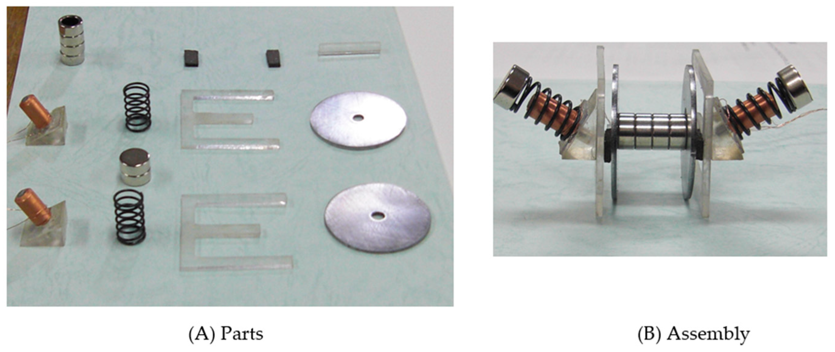
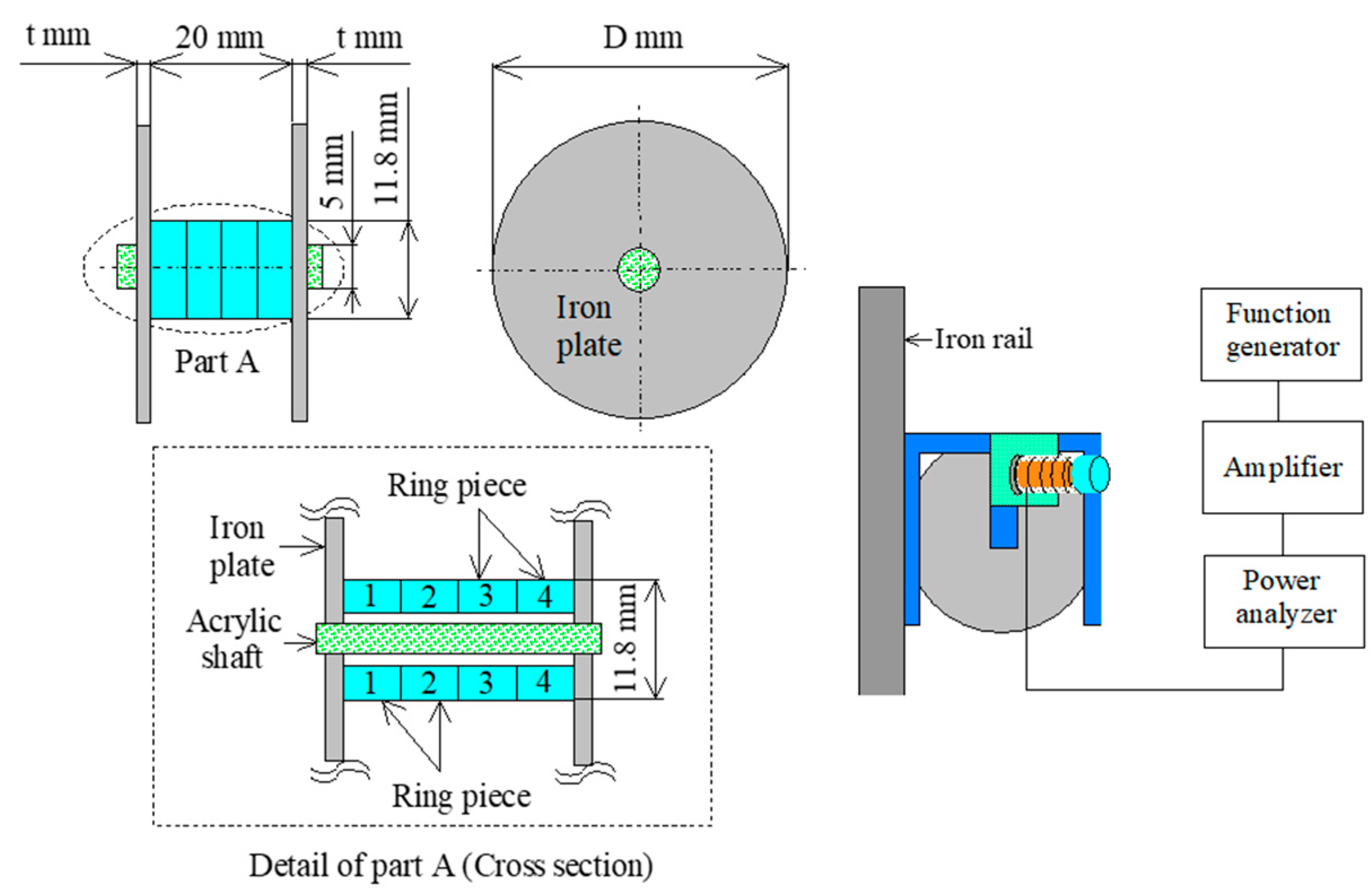
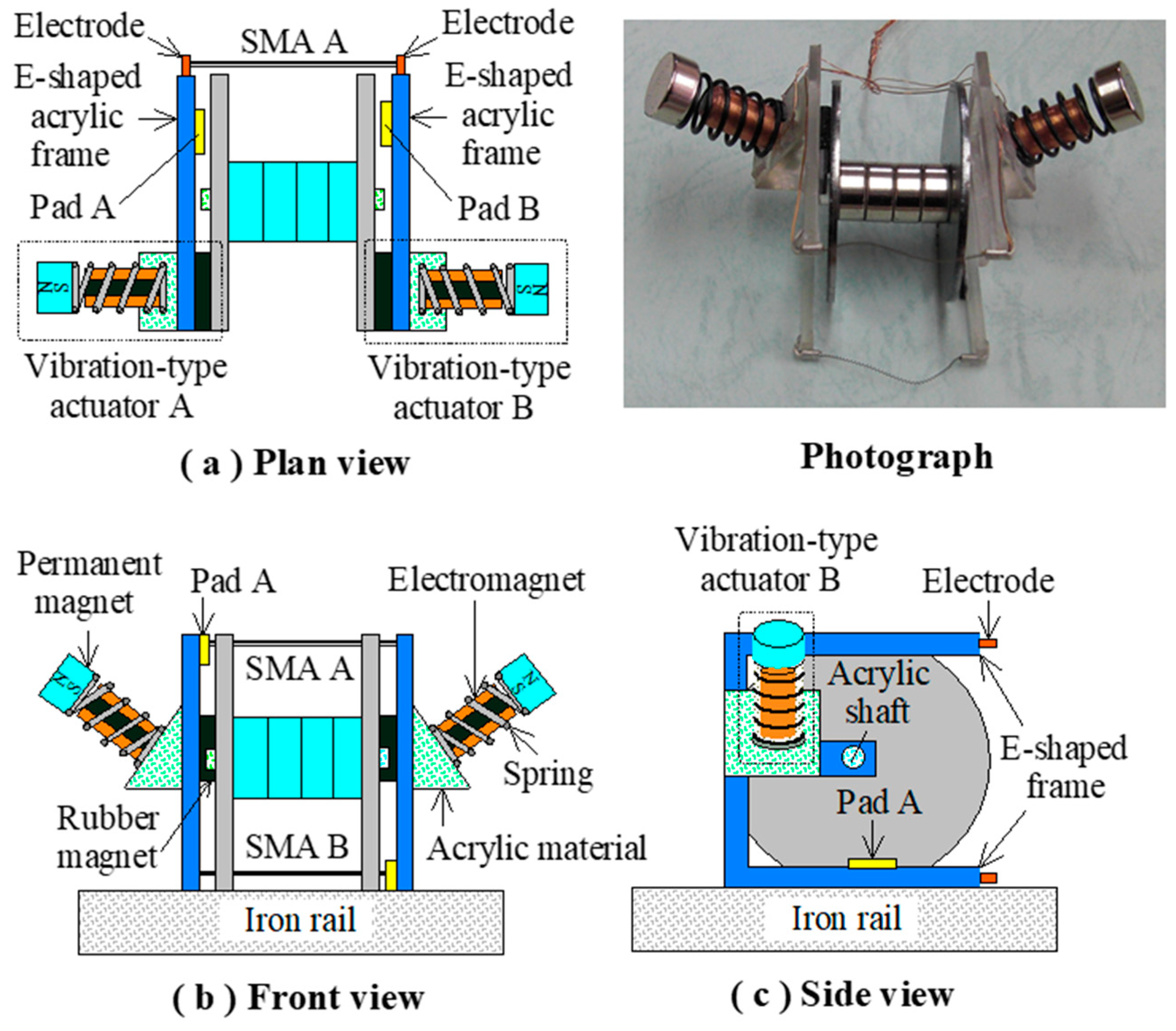
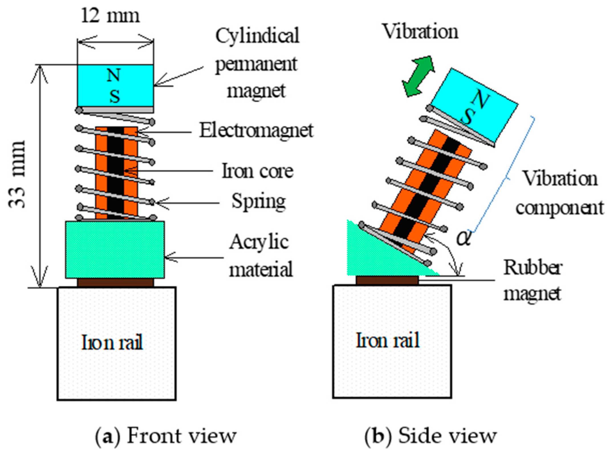
2. Structure of the Vibration-Type Actuator and Actuator System
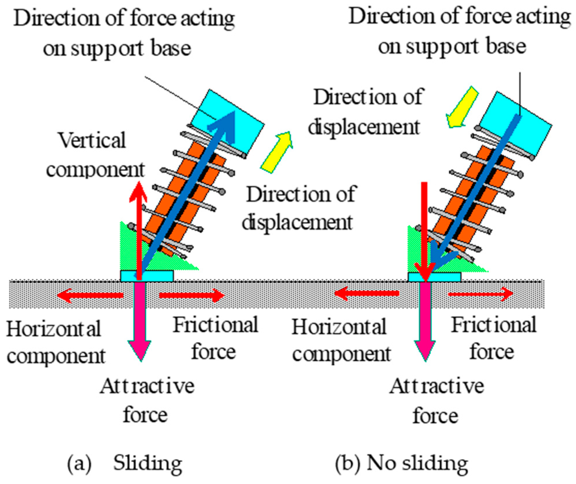
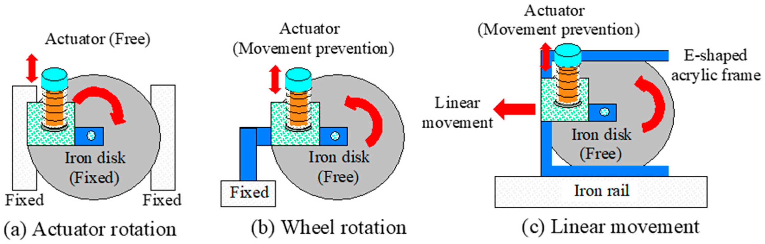
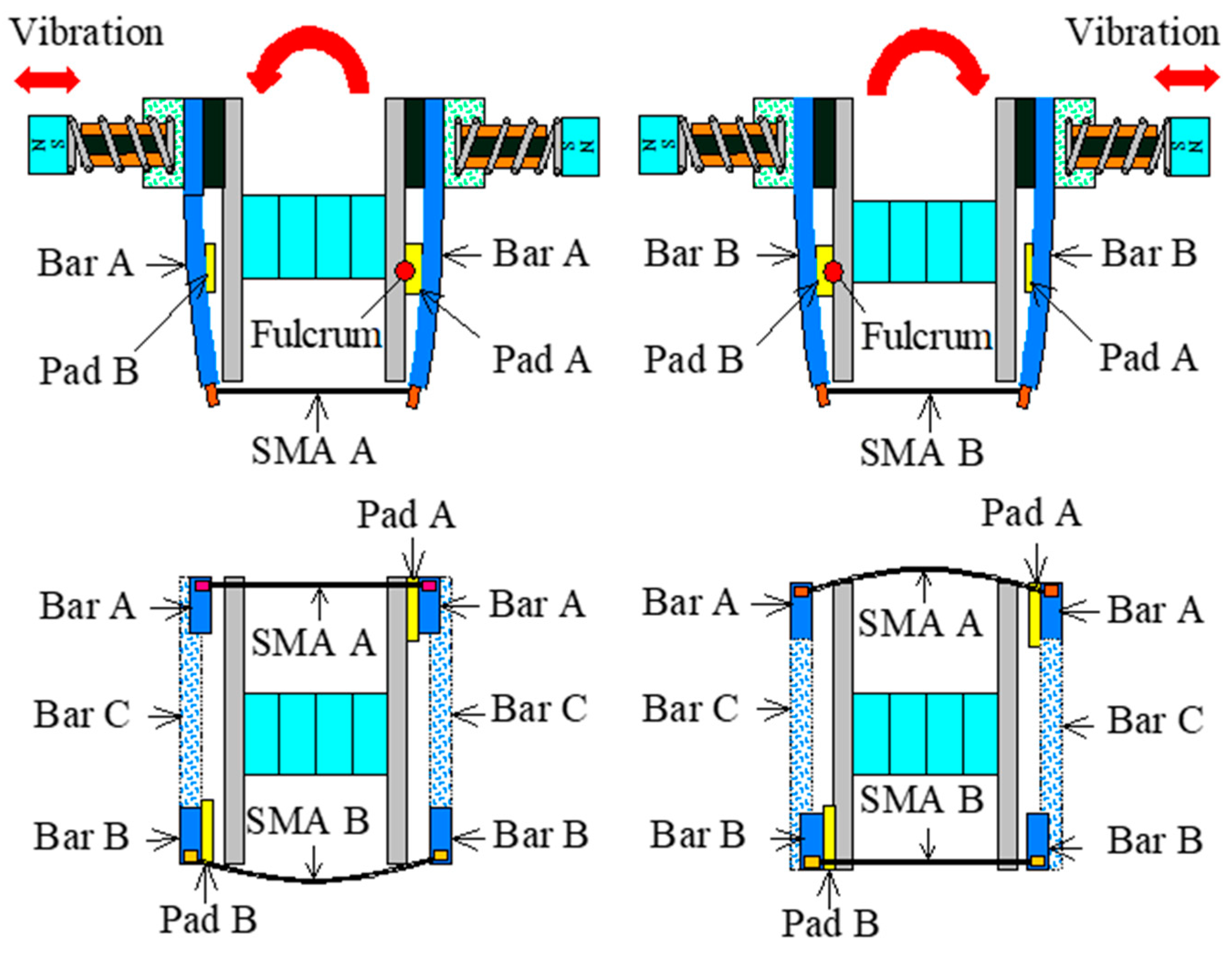
3. Principle of Locomotion
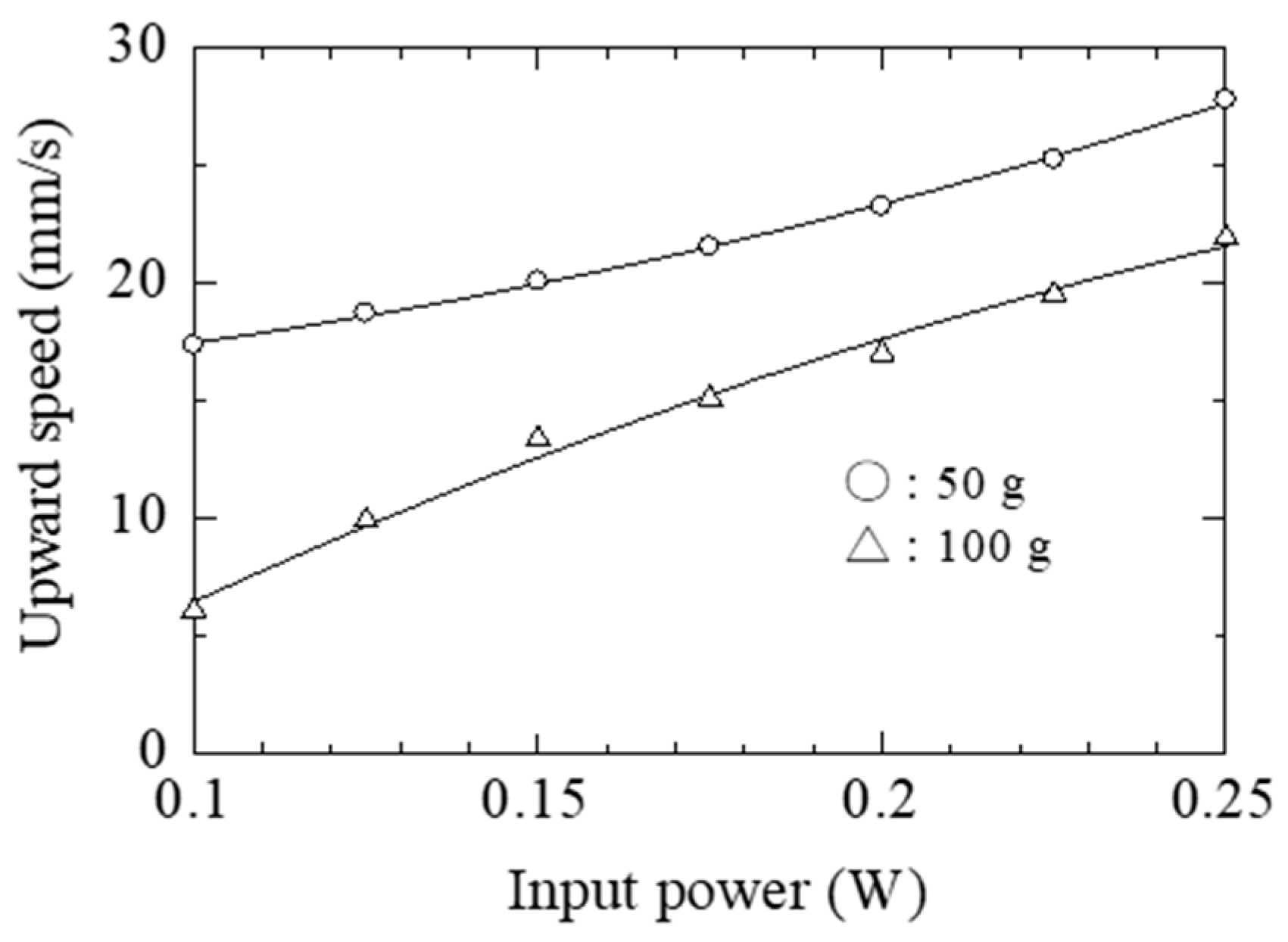
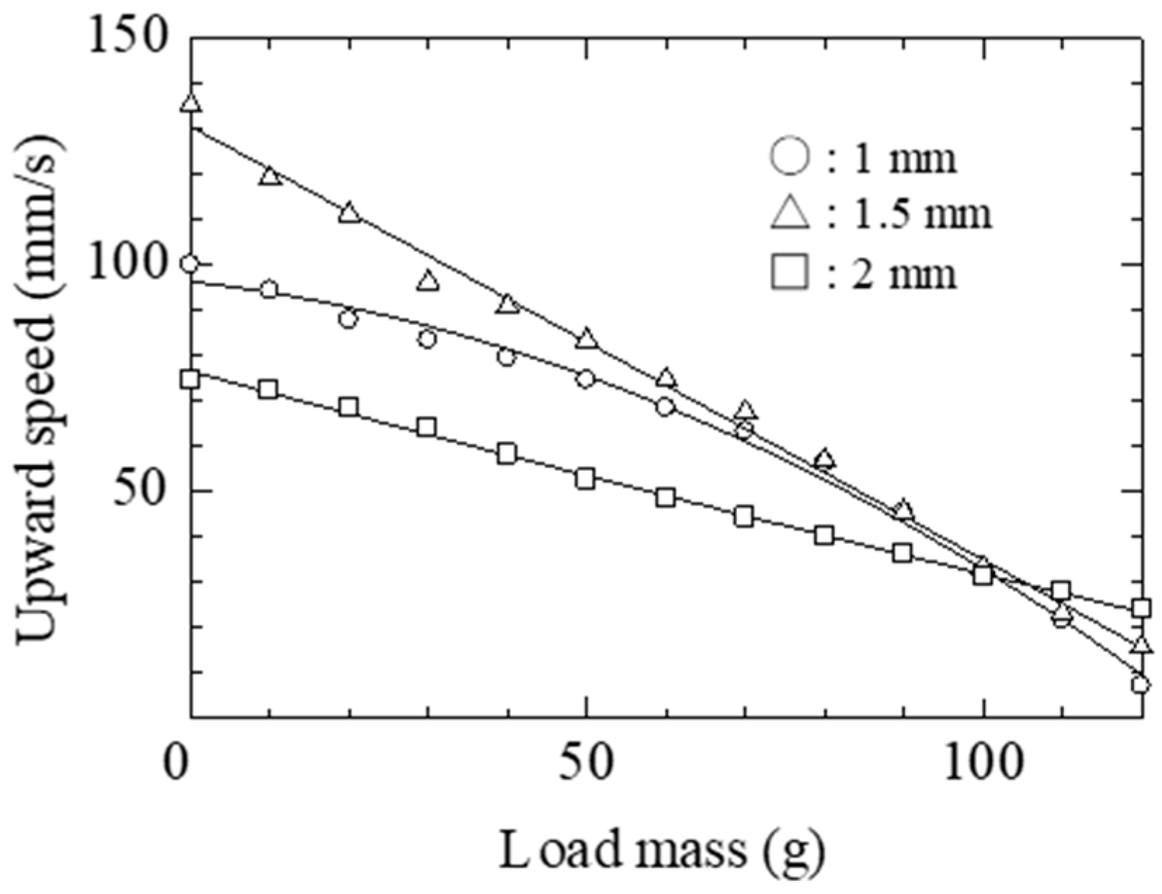
4. Locomotive Characteristics of Actuator System
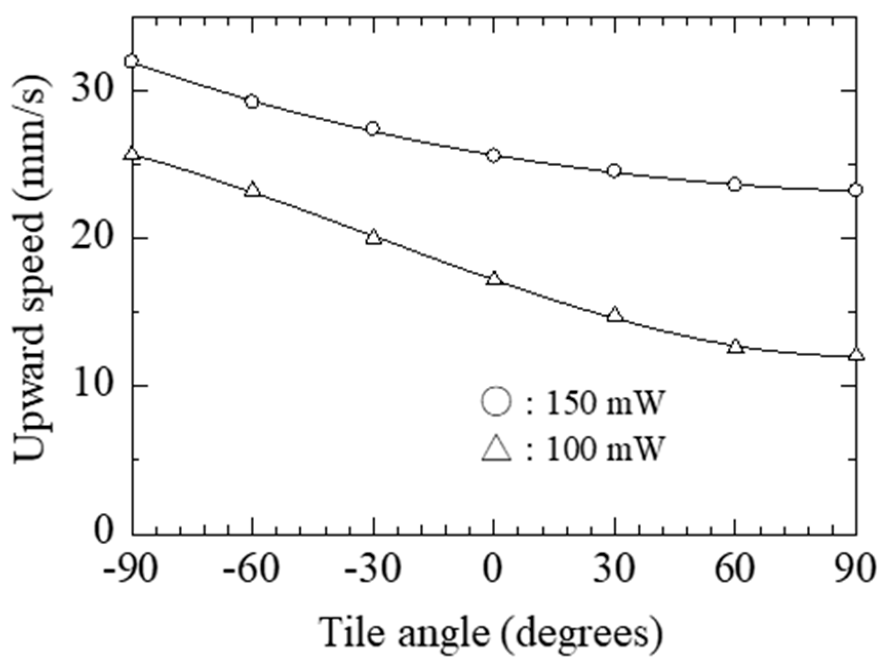
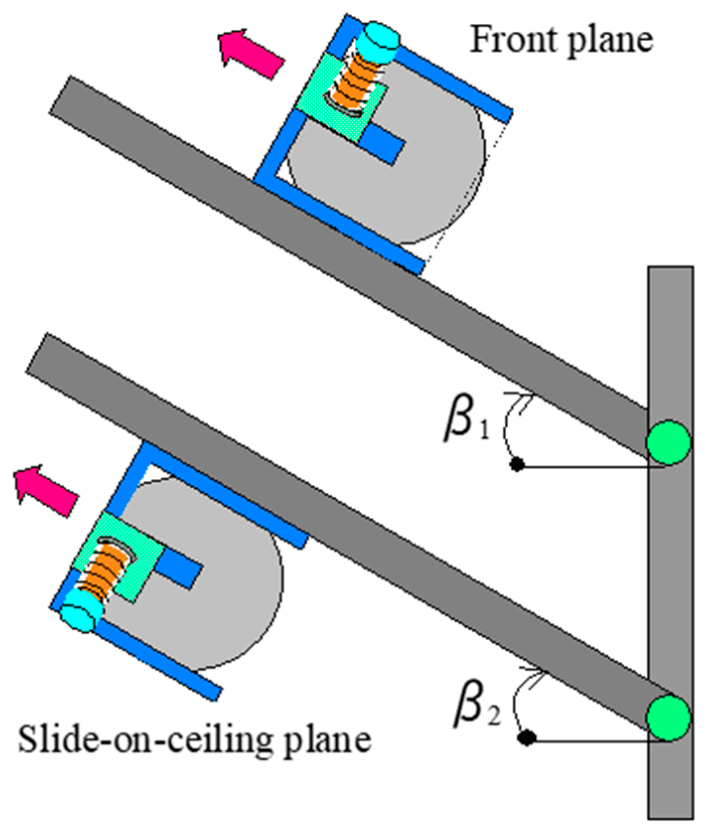
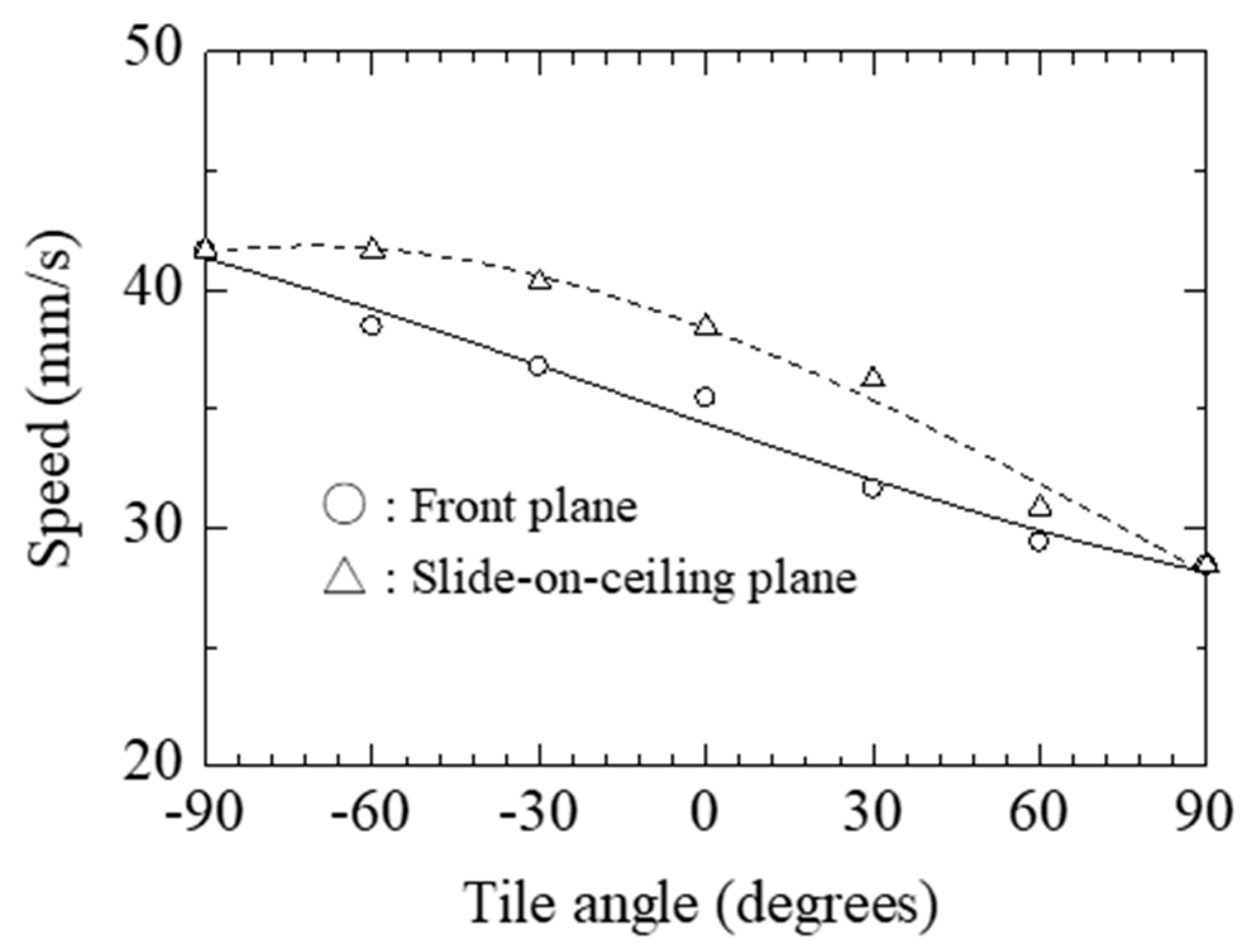
5. Turning Properties of the Actuator System
6. Conclusions
Author Contributions
Conflicts of Interest
References
- Shen, W.; Gu, J.; Shen, Y. Permanent Magnetic System Design for the Wall-Climbing Robot. In Proceedings of the IEEE International Conference on Mechatronics & Automation, Beijing, China, 7–10 August 2011. [Google Scholar]
- Lee, G.; Park, J.; Kim, H.; Seo, T.W. Wall Climbing Robots with Track-wheel Mechanism. In Proceedings of the IEEE International Conference on Machine Learning and Computing, Guillin, China, 10–13 July 2011. [Google Scholar]
- Fukuda, T.; Matsuura, H.; Arai, F.; Nishibori, K.; Sakauchi, H.; Yoshi, N. A Study on Wall Surface Mobile Robots. Trans. Jpn. Soc. Mech. Eng. 1992, 58, 286–293. [Google Scholar]
- Kawasaki, S.; Kikuchi, K. Development of a Small Legged Wall Climbing Robot with Passive Suction Cups. In Proceedings of the International Conference on Design Engineering and Science, Pilsen, Czech Republic, 31 August–3 September 2014. [Google Scholar]
- Yoshida, Y.; Ma, S. A Wall-Climbing Robot without any Active Suction Mechanisms. In Proceedings of the IEEE International Conference on Robotics and Biomimetics, Karon Beach, Thailand, 7–11 December 2011. [Google Scholar]
- Miyake, T.; Ishihara, H.; Yoshimura, M. Basic Studies on Wet Adhesion System for Wall Climbing Robot. In Proceedings of the IEEE/RSJ International Conference on Intelligent Robots and Systems, San Diego, CA, USA, 29 October–2 November 2007. [Google Scholar]
- Apostolescu, T.C.; Udrea, C.; Duminica, D.; Ionascu, G.; Bogatu, L.; Cartal, L.A. Development of a Climbing Robot with Vacuum Attachment Cups. In Proceedings of the International Conference on Innovations, Recent Trends and Challenges in Mechatronics, Bucharest, Romania, 22–23 September 2011. [Google Scholar]
- Akhtaruzzaman, M.; Samsuddin, N.; Umar, N.; Rahman, M. Design and Development of a Wall Climbing Robot and its Control System. In Proceedings of the International Conference on Computer and Information Technology, Dhaka, Bangladesh, 21–23 December 2009. [Google Scholar]
- Suzuki, M.; Hirose, S. Proposal of Swarm Type Wall Climbing Robot System Anchor Climber and Development of Adhering Mobile Units. Robot. Soc. Jpn. 2010, 28, 614–623. [Google Scholar] [CrossRef]
- Khirade, N.; Sanghi, R.; Tidke, D. Magnetic Wall Climbing Devices—A Review. In Proceedings of the International Conference on Advances in Engineering & Technology, Singapore, 29–30 March 2014. [Google Scholar]
- Kim, J.H.; Park, S.M.; Kim, J.H.; Lee, J.Y. Design and Experimental Implementation of Easily Detachable Permanent Magnet Reluctance Wheel for Wall-Climbing Mobile Robot. J. Magn. 2010, 15, 128–131. [Google Scholar] [CrossRef] [Green Version]
- Yoon, K.H.; Park, Y.W. Controllability of Magnetic Force in Magnetic Wheels. IEEE Trans. Magn. 2012, 48, 4046–4049. [Google Scholar] [CrossRef]
- Kim, H.; Kim, D.; Yang, H.; Lee, K.; Seo, K.; Chang, D.; Kim, J. Development of a wall-climbing robot using a tracked wheel mechanism. J. Mech. Sci. Technol. 2008, 22, 1490–1498. [Google Scholar] [CrossRef]
- Subramanyam, A.; Mallikarjuna, Y.; Suneel, S.; Kumar, L.B. Design and Development of a Climbing Robot for Several Applications. Int. J. Adv. Comput. Technol. 2011, 3, 15–23. [Google Scholar]
- Panich, S. Development of a Climbing Robot with Vacuum Attachment Cups. J. Comput. Sci. 2010, 6, 1185–1188. [Google Scholar] [CrossRef]
- Jae-Uk, S.; Donghoon, K.; ong-Heon, J.; Hyun, M. Micro aerial vehicle type wall-climbing robot mechanism. In Proceedings of the IEEE RO-MAN International Symposium on Robot and Human Interactive Communication, Gyeongju, Korea, 26–29 August 2013. [Google Scholar]
- Wang, K.; Wang, W.; Li, D.; Zong, G.; Zhang, H.; Zhang, J.; Deng, Z. Analysis of Two Vibrating Suction Methods. In Proceedings of the IEEE International Conference on Robotics and Biomimetics, Bangkok, Thailand, 22–25 February 2009. [Google Scholar]
- Wang, W.; Wang, K.; Zhang, H.; Zhang, J. Internal Force Compensating Method for Wall-Climbing Caterpillar Robot. In Proceedings of the IEEE International Conference on Robotics and Automation, Anchorage, AK, USA, 3–7 May 2010. [Google Scholar]
- Xu, F.; Wang, X.; Jiang, G. Design and Analysis of a Wall-Climbing Robot Based on a Mechanism Utilizing Hook-Like Claws. Int. J. Adv. Rob. Syst. 2012, 9, 1–12. [Google Scholar] [CrossRef]
- Funatsu, M.; Kawasaki, Y.; Kawasaki, S.; Kikuchi, K. Development of cm-scale Wall Climbing Hexapod Robot with Claws. In Proceedings of the International Conference on Design Engineering and Science, Pilsen, Czech Republic, 31 August–3 September 2014. [Google Scholar]
- Provancher, W.; Jensen-Segal, S.; Fehlberg, M. ROCR: An Energy-Efficient Dynamic Wall-Climbing Robot. IEEE Trans. Mechatron. 2011, 16, 897–906. [Google Scholar] [CrossRef]
- Kute, C.; Murphy, M.; Menguc, Y.; Sitti, M. Adhesion Recovery and Passive Peeling in a Wall Climbing Robot using Adhesives. In Proceedings of the IEEE International Conference on Robotics and Automation, Anchorage, AK, USA, 3–7 May 2010. [Google Scholar]
- Unver, O.; Sitti, M. Tankbot: A Miniature, Peeling Based Climber on Rough and Smooth Surfaces. In Proceedings of the IEEE International Conference on Robotics and Automation, Kobe, Japan, 12–17 May 2009. [Google Scholar]
- Yaguchi, H.; Sakuma, S. A Novel Magnetic Actuator Capable of Free Movement on a Magnetic Substance. IEEE Trans. Magn. 2015, 51, 8206204. [Google Scholar] [CrossRef]
- Yaguchi, H.; Sakuma, S. Vibration Actuator Capable of Movement on Magnetic Substance Based on New Motion Principle. J. Vibroeng. 2017, 19, 1494–1508. [Google Scholar]


| Diameter (mm) | Total Mass (g) | ||
|---|---|---|---|
| Thickness: 1 mm | Thickness: 1.5 mm | Thickness: 2 mm | |
| 40 mm | 56.4 | 66 | 75.64 |
| 50 mm | 73.5 | 83.1 | 92.7 |
| 60 mm | 103.8 | 113.4 | 123 |
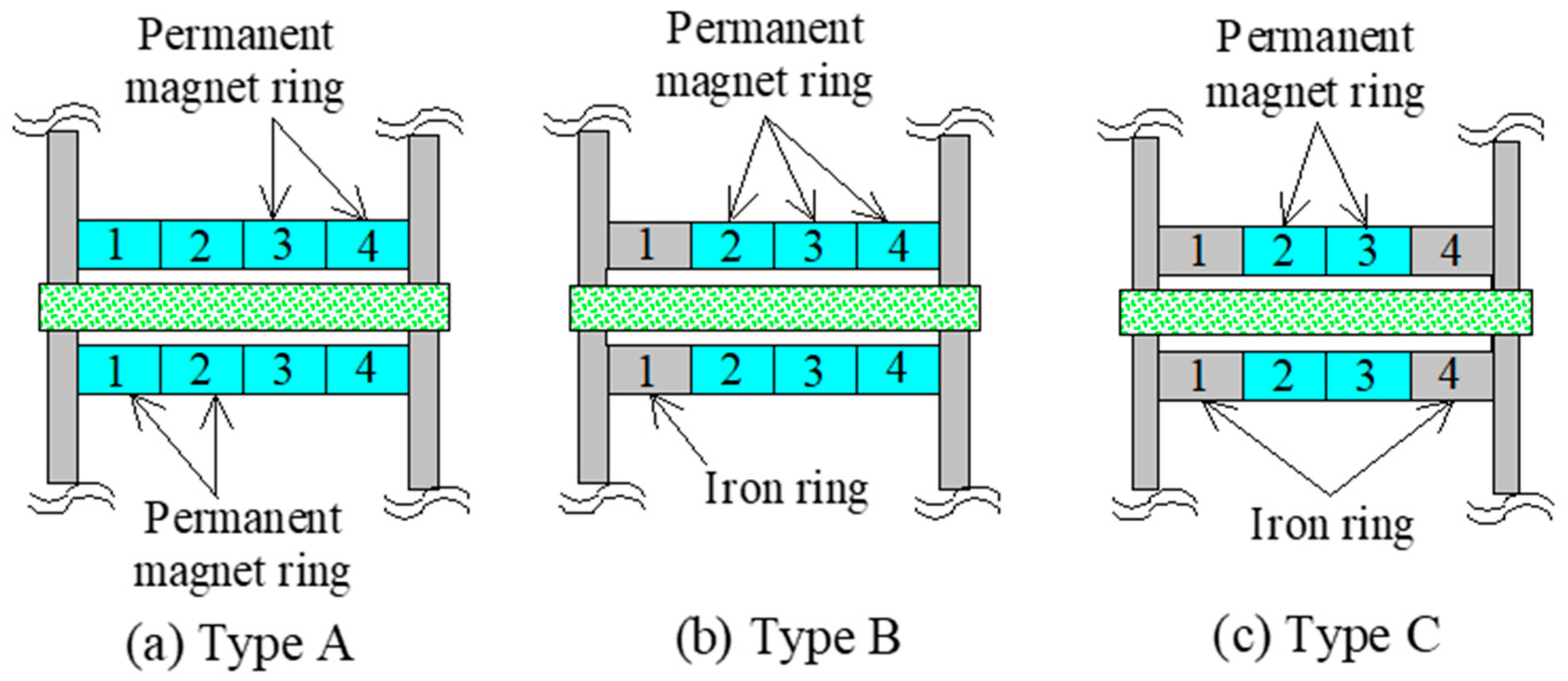
| Magnetic Ring | Attractive Force (N) | ||
|---|---|---|---|
| Thickness: 1 mm | Thickness: 1.5 mm | Thickness: 2 mm | |
| Type A | 9.3 | 15.1 | 16 |
| Type B | 9 | 14.9 | 15 |
| Type C | 8.9 | 14.3 | 14.8 |
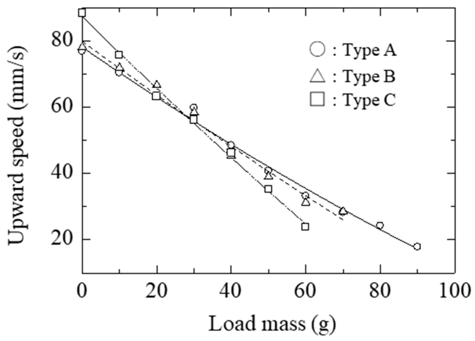
| Diameter (mm) | Speed (mm/s) | ||
|---|---|---|---|
| Type A | Type B | Type C | |
| 40 mm | 41.7 | 37.9 | 34.5 |
| 50 mm | 35.77 | 32.1 | 30.3 |
| 60 mm | 29.1 | 26.7 | 25 |
| Outer Diameter | Diameter of Wire | Transformation Point | Resistance per Meter | Input Current | |
|---|---|---|---|---|---|
| SMA coil spring | 0.62 mm | 150 μm | 60–65 °C | 400 Ω | 180 mA |
| Vertical Plane | Horizontal Plane | ||
|---|---|---|---|
| Clockwise (°/s) | Counter Clockwise (°/s) | Clockwise (°/s) | Counter Clockwise (°/s) |
| 12 | 11 | 20 | 21 |
© 2019 by the authors. Licensee MDPI, Basel, Switzerland. This article is an open access article distributed under the terms and conditions of the Creative Commons Attribution (CC BY) license (http://creativecommons.org/licenses/by/4.0/).
Share and Cite
Yaguchi, H.; Kimura, I.; Sakuma, S. A Novel Actuator System Combining Mechanical Vibration and Magnetic Wheels Capable of Rotational Motion Using Shape Memory Alloy Coils. Actuators 2019, 8, 4. https://doi.org/10.3390/act8010004
Yaguchi H, Kimura I, Sakuma S. A Novel Actuator System Combining Mechanical Vibration and Magnetic Wheels Capable of Rotational Motion Using Shape Memory Alloy Coils. Actuators. 2019; 8(1):4. https://doi.org/10.3390/act8010004
Chicago/Turabian StyleYaguchi, Hiroyuki, Izuru Kimura, and Shun Sakuma. 2019. "A Novel Actuator System Combining Mechanical Vibration and Magnetic Wheels Capable of Rotational Motion Using Shape Memory Alloy Coils" Actuators 8, no. 1: 4. https://doi.org/10.3390/act8010004
APA StyleYaguchi, H., Kimura, I., & Sakuma, S. (2019). A Novel Actuator System Combining Mechanical Vibration and Magnetic Wheels Capable of Rotational Motion Using Shape Memory Alloy Coils. Actuators, 8(1), 4. https://doi.org/10.3390/act8010004