Abstract
Pump-controlled hydraulic circuits offer an energy-efficient solution for many applications. They combine the high power to weight ratio of hydraulic technology with the ease of control of electric technology. Pump-controlled circuits for double-rod cylinders are well developed as compared to those of single-rod cylinders. In spite of many initiatives, certain common pump-controlled single-rod cylinder solutions present stability issues during specific modes of operation. Common examples of the solutions are circuits that utilize pilot-operated check valves and circuits that use shuttle valves. In these circuits, velocity oscillations have been reported during actuator retraction at low assistive loads. In this paper, we study the area on the load-velocity graph of the available circuits where oscillatory behavior is experienced. We then propose a solution that shifts this critical zone towards lower loading values. This in turn reduces system response oscillations. Shifting the critical zone is accomplished by utilizing two charge pressures and asymmetric flow compensating valves. The concept is evaluated via simulations and experiments. Our results clearly show the enhanced performance of the circuits incorporating the proposed solution.
1. Introduction
Valve-controlled hydraulic systems possess a high power to weight ratio, fast response, and high stability under variable loading conditions. One main disadvantage of these systems, however, is their low efficiency [1,2,3]. Pump-controlled hydraulic circuits are more efficient than valve-controlled circuits [4,5,6]. Pump-controlled circuits for double-rod cylinders are well developed and already in use in many applications, for example in aviation [7,8]. In spite of the many efforts to develop pump-controlled circuits for single-rod cylinders [9,10,11,12,13], none of these designs have yet been adopted by industry. The main issue is the undesirable oscillations during some modes of operation. Rahmfeld and Ivantysynova [14] introduced a closed circuit that comprises two pilot-operated check valves to compensate for the differential flow of an asymmetric cylinder. Williamson and Ivantysynova [15] reported that the pump-controlled circuit with two pilot-operated check valves experiences oscillations during a specific mode of operation, specifically when the actuator retracts at light loads and high velocities. Sebastian et al. [16] introduced an analytical approach that relates the existence of the system oscillations to acceleration rates of the inertial load. Avoiding the pre-determined undesirable acceleration rates protects the system against oscillations. Wang et al. [11] proposed a circuit that incorporates a three-way, three-position closed-center shuttle valve to compensate for the actuator differential flow. They reported that the system response becomes oscillatory when the load acting on the actuator reaches a certain value. They identified this critical load as the load equivalent to the actuator bias force when pressures in both chambers of the actuator are equal to the charge pressure. To deal with the issue of velocity oscillation, they applied a controlled leakage through two electrically controlled regulating valves. Caliskan et al. [13] utilized a three-way, three-position open-center shuttle valve to improve stability through valve leakage. Using the load-velocity plane, they showed the critical zone where undesirable velocity oscillations occur. Imam et al. [3] further showed the effect of the charge pressure, actuator area ratio, transmission line losses and friction on the location and shape of this critical zone.
In this paper, a new concept to improve the performance and reduce the reported system oscillations of pump-controlled closed circuits for single-rod actuators is proposed. This concept is based on shifting the critical zone towards lower loading values. Such an action reduces the adverse effects of oscillating load on the machine. The proposed concept is applied to circuits that utilize either pilot-operated check valves or shuttle valves. Simulations and experimental evaluations show the enhanced performance of the proposed approach.
2. Problem Statement and Proposed Solution
Figure 1a shows a schematic drawing of the pump-controlled circuit that utilizes pilot-operated check valves (POCVs) [14]. This circuit consists of a variable-displacement swash plate piston-pump, two POCVs and a low-pressure charge system (CH). POCVs are used to compensate for the cylinder differential flow; they open through pilot signals from the cross pressure lines as the circuit operates in the four quadrants of operation.
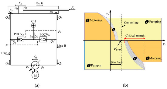
Figure 1.
Circuit that incorporates two pilot-operated check valves (POCVs) and a charge pressure (CH): (a) schematic drawing; (b) construction of critical zone (regions 5 and 6) according to Reference [3].
Consider extending the actuator against an external resistive load, as shown in Figure 1a. The pump delivers flow to the cap side of the cylinder through transmission line A. As the pressure in line A builds up, it opens the cross pilot-operated check valve, POCVB. Consequently, the charge line connects to line B, which allows flow, , to compensate for the cylinder differential flow. In this case, the main pump works in pumping mode. Circuits with POCVs experience velocity oscillations during actuator retraction at light loads and high velocities [15]. In our previous work [3], a realistic graph of the critical zone for circuits that utilize POCVs was presented that is reproduced in Figure 1b. It is clear from Figure 1b that the critical zone consists of two regions, 5 and 6, located to the left- and right-hand sides of the center line. The center line is the vertical line passing through the critical load, . Critical load corresponds to actuator bias force when pressures at both sides of the actuators are equals to the charge pressure i.e., , where is the charge pressure. and are piston cap- and rod-side areas, respectively. Note that, the critical zone size in Figure 1b is not scaled; it is shown much larger than the real size for demonstration purposes. Region 5 represents the switching zone in which the pump mode of operation switches from motoring to pumping during actuator extension. The pressures on both sides of the circuit are almost equal and less than the charge pressure which keeps both POCVs and/or anti-cavitation valves open. In this case, the charge pump supplies both sides of the circuit with hydraulic flow and the actuator velocity is not fully controllable [3,6]. Region 6 happens during actuator retraction and exhibits velocity oscillations. Note that critical region 6 increases in area and the amplitudes of velocity oscillations increase as the load experienced by the actuator increases. It is also noted that the critical zone is asymmetric around the zero-load axes, which results in shifting the oscillatory critical region 6 to a higher load margin on the load axis. Oscillations at higher load values are more severe in amplitude and consequently are very destructive for the machine. The shifted position of the critical zone is attributed to the creation of the actuator bias force at the zero-control signal condition. The values of the bias force depend on the charge pressure and the differential area of the piston [3]. Shifting the critical zone into a symmetric position around the zero-load axes reduces the load experienced by the actuator where velocity oscillations potentially occur. Consequently, the destructive effects of the oscillations are reduced. Note that region 5 (see Figure 1b) may reach higher load values; however, this situation can be tolerated since this region does not exhibit oscillatory behavior.
One way to shift the critical zone is by nullifying the actuator bias force, which results in shifting the center line to the zero-load axis. Referring to the equation that defines center line, , where the area ratio , two trivial solutions to obtain zero-load center-line are: (i) choosing which means using a symmetric (double-rod) cylinder, (ii) reducing the charge pressure to zero, (), which means using a non-pressurized oil tank. Apparently, these solutions are not acceptable. A non-zero pressure charging system is crucial in a closed circuit to: (i) Compensate for the differential flow of a single-rod actuator at different quadrants of operation, (ii) avoid pump cavitation through supplying low-pressure flow to either ports of the pump, and (iii) supply low-pressure flow to cool down and lubricate the pump internal components.
One non-trivial solution to shift the critical zone is to utilize two different charge pressures in the circuit. Using this concept, each side of the circuit is connected through the compensating valve to a separate charge system. Figure 2 illustrates the drawing of the proposed circuit with two charge pressures and the corresponding critical zone. The charge pressures are selected such that the pressure force at each side of the actuator, at zero velocity, are equal, i.e., and consequently, . As a result of using two different charge pressures, two POCVs with two different cracking pressures are used to keep proper functionality of the circuit.
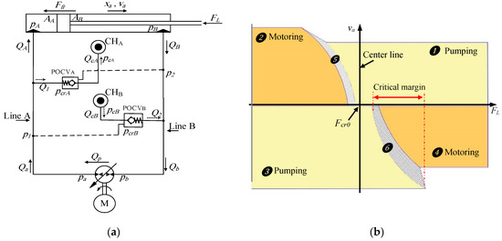
Figure 2.
Proposed circuit that incorporates two charge pressures and two non-identical pilot-operated check valves: (a) schematic drawing; (b) construction of new critical zone.
2.1. Mathematical Model
The mathematical model for the modified circuit (Figure 2) with two charge pressures and two non-identical POCVs is described first. With reference to Figure 2, the mathematical model of the actuator is represented by the piston equation of motion and flow continuity equations at both chambers of the cylinder:
where represents the equivalent moving mass; cylinder velocity and displacement are denoted as and ; denotes external force; pressures at actuator ports are represented by and . and are the flow rates to and from the actuator ports; is the oil bulk modulus. The oil volumes at each side of the cylinder are represented by and , where and ; and are the volumes of oil in the cap and rod sides of the actuator, respectively, where the actuator is at its initial position ().
Friction force, , is assumed to be the summation of the Coulomb and viscous friction forces. The Coulomb friction force in the internal oil seals of the hydraulic actuator is considered to be a function of the seal preload force and pressures at both chambers of the actuator [16]. Friction force equations are represented as follows:
where is the Coulomb friction force; and represent the breakaway friction force increase and velocity transition coefficients, respectively; and denote the viscous and Coulomb friction coefficients, respectively; is the preload force needed to fit oil seals into place. To avoid discontinuity in the friction model at , a small region around zero velocity where is less than a threshold velocity is introduced. In this region, the friction force is assumed to be linearly proportional to velocity, . System oscillations occur at low pressures where pump internal leakage is neglected and pump flow is considered as a linear function of the pump input voltage:
where is the linearized coefficient for pump flow. Flow balance at both sides of the circuit are represented by the following equations:
Losses in transmission lines are introduced using the lumped resistance model. This model relates the pressure drop in a transmission line to the resistance of viscous laminar flow in line and local losses due to momentum change in fittings and different restrictions; pressure drop in a transmission line can be represented as follows [17]:
where is the combined viscous friction coefficient in transmission lines, and is the local drag coefficient. Note that is the fluid dynamic viscosity; and are the transmission line length and diameter; fluid density is denoted as ; and represents the local losses coefficient.
Figure 3 illustrates a schematic drawing of the pilot-operated check valve positioned in the left-hand side of the circuit (POCVA). According to the notations in Figure 2, flow through POCVA opening is represented by the following equation [18]:
where is the flow discharge coefficient through POCVA throttling; represents the opening area of POCVA; charge pressure connected to POCVA is denoted as . The cracking condition of the POCVs depends on the valve piloting and outlet pressures referenced to the charge pressure [19]. The dynamics of the POCVs have little effect on the overall circuit dynamics; thus, it is neglected. Instead, the static force balance of the valve poppet is used.
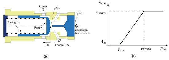
Figure 3.
Pilot-operated check valve in Line A of the circuit (POCVA): (a) schematic drawing; (b) opening area versus effective pressure. and represent the pressure required to fully open the valve passage and corresponding maximum opening area, respectively.
The static force balance of POCVA poppet, shown in Figure 3a, can be represented as follows:
where and are the pilot piston and poppet effective areas, respectively; and represent spring initial force and stiffness, respectively; poppet displacement is denoted as . By dividing Equation (12) by the poppet effective area, , and considering the critical opening condition of the valve, i.e., , the following pressure balance equation is obtained:
where is the piloting ratio of the valve. For simplicity, we introduce the effective opening pressure, , as the summation of the effective pressures that opens POCVA, i.e., . Assuming that the valve opening area is a linear function of the effective opening pressure, as shown in Figure 3b, the opening area of POCVA can be formulated as follows:
In Equation (14), is the POCVA opening area coefficient; and represent the pressure required to fully open the valve passage and corresponding maximum opening area, respectively. and are shown in Figure 3b.
2.2. Simulation Studies
Simulations were performed to show the effectiveness of the proposed modifications on the behavior of the POCV-type circuit. The simulation program was developed in MATLAB environment. Figure 4 and Figure 5 show simulation results of the critical zone size and location as well as the velocity responses for the original circuit (shown in Figure 1) and that of the proposed circuit (represented in Figure 2). The values of the parameters used in simulation are listed in Table 1.
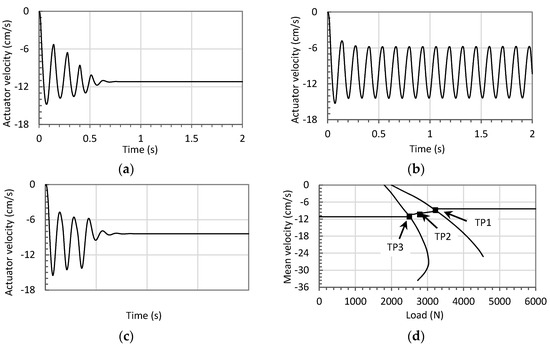
Figure 4.
Simulation results of the velocity responses in the critical zone for the conventional circuit (Figure 1). (a) Actuator velocity versus time at test point 1 (TP1) (FL = 3080 N); (b) actuator velocity response at test point 2 (TP2) (FL2 = 2660 N); (c) velocity response at test point 3 (TP3) (FL3 = 2300 N); (d) construction of the critical region.
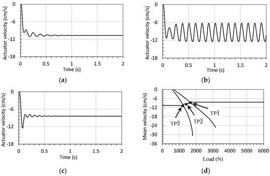
Figure 5.
Simulation results of the velocity responses in the critical zone for the proposed circuit (Figure 2). (a) Actuator velocity versus time at test point 1 (TP) (FL1 = 2600 N); (b) velocity response at test point 2 (TP) (1430 N); (c) velocity response at test point 3 (TP) (1180 N); (d) construction of the critical region.

Table 1.
Values of parameters used in simulations.
The performance during switching zone in both circuits was shown by tracking the responses of three selected operating points given a step control signal input of −4 V. The test points were chosen at the beginning, middle, and end of the critical zone to show velocity oscillations behavior in the critical zone.
Figure 4a–c show the actuator velocity responses versus the time for the original circuit at test point 1 (TP1) (FL = 3080 N), test point 2 (TP2) (2660 N), and test point 3 (TP3) (2300 N), whereas Figure 4d shows the construction of the critical zone of the circuit and selected test points. Figure 5a–c represent the actuator velocity responses at test points TP (FL = 2600 N), TP (1430 N), and TP (1180 N) for the proposed circuit, while the construction of the critical zone of the proposed circuit and position of the test points are shown in Figure 5d. It is clear that the velocity oscillations in the proposed circuit, at the three test points, are less severe as compared to the original circuit. Figure 4d and Figure 5d compare the critical zones for previously designed (Figure 1) and proposed (Figure 2) circuits, respectively. The responses are classified and graphed on the load-velocity plane based on the quality of the simulation responses. More specifically, if the velocity oscillations lasted over 0.6 s, the corresponding operating point was considered to be oscillatory and was included as part of the critical zone. Note that it is quite difficult to specify a generalized criterion for oscillatory behavior. Different applications have different criterion. The 0.6 s period was chosen since in our experiments, it shows noticeable oscillations. Comparing Figure 4d and Figure 5d, it is clear that the area of the critical zone in the proposed circuit reduced in size and shifted towards lower loading values. Figure 6 shows the velocity oscillation amplitudes at operating points inside the critical zones for different loads given a step control signal input of −4 V. It is clear from Figure 6 that the critical zone in the proposed circuit reduced in size and shifted towards a lower loading margin as compared to that of the original design (Figure 2). Width and maximum velocity oscillation amplitudes of the critical zone in the proposed circuit are 330 N and 3.3 cm/s as compared to 660 N and 4.4 cm/s for the original circuit (Figure 1). Comparing rated energy by the actuator, FLva, during oscillations, a lot less rated energy is seen in modified circuits. For instance, the maximum rated energies at oscillatory points TP2 and TP are determined to be 2660 N × 0.145 m/s = 385.7 W and 1430 N × 0.125 m/s = 178.8 W in the original and proposed circuits, respectively.
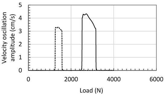
Figure 6.
Simulation results of velocity oscillation amplitudes versus load for the conventional (solid line) and proposed (dashed line) circuits that use POCVs.
3. Extension of Approach to Circuits that Utilize Shuttle Valves
The concept of shifting the critical zone is also applicable to pump-controlled circuits that are equipped with shuttle valves. These circuits utilize either closed-center shuttle valves (CC-SHVs) [11] or open-center shuttle valves (OC-SHVs) [13], as shown in Figure 7a,b, respectively. The proposed concept is applied by utilizing two different charge pressures and biased shuttle valves. Figure 8a,b show the proposed circuits.
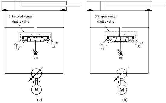
Figure 7.
Circuit with one charge pressure and (a) a 3/3 closed-center shuttle valve and (b) a 3/3 open-center shuttle valve.
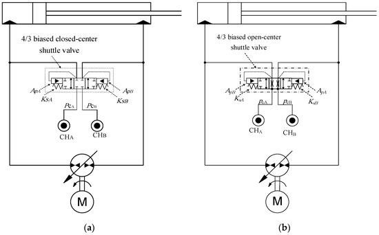
Figure 8.
Circuit with two charge pressures and (a) a 4/3 biased closed-center shuttle valve and (b) a 4/3 biased open-center shuttle valve.
3.1. Mathematical Model
Figure 9 shows the circuit with the 4/3 biased closed-center shuttle valve (CC-SHV) operating in the first (pumping) quadrant mode. The mathematical model of this circuit is derived below. Figure 10a,b show the schematic of the valve and areas of the two openings as a function of the effective pressure acting on the spool. The flow through the valve openings is represented by the following equations [18]:
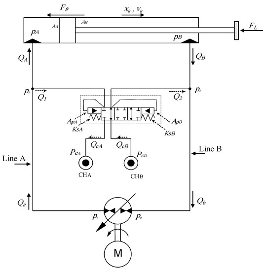
Figure 9.
Circuit that utilizes two charge pressures and a 4/3 closed-center biased shuttle valve (as shown in Figure 10), operating in first quadrant of operation.
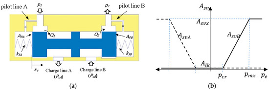
Figure 10.
Schematic of 4/3 biased closed-center shuttle valve: (a) schematic drawing; (b) the areas of the flow openings as function of the effective pressure.
The opening of the shuttle valve (SHV) depends on the pressure difference between the two main lines, the spool area, and the stiffness of the centering springs. The SHV dynamics are neglected because their effect on the overall circuit dynamics is not significant. The force balance of the spool is therefore represented as follows:
In Equation (17), the spool areas ( and ) and the balancing springs stiffness ( and ) are chosen such that the spool is balanced in a neutral position when the piloting pressures are equal to the charge pressures. Here, we consider the case where two similar springs and two different spool effective areas are used. In this case, the static force balance of the spool can be represented as follows:
Dividing the above equation by , and assuming operation around the critical opening condition, , we obtain the following pressure balance equation:
where is the valve spool area ratio. To achieve the proper operation of the valve, the resultant pressure force applied to the spool has to be null at the zero-control signal condition. Consequently, is chosen based on the ratio of the charge pressures or actuator area ratios. Note that the same ratio would be chosen in the case of creating the valve biasness through utilizing two different balancing springs.
We now introduce the effective opening pressure, , as the summation of the pressures acting on the spool, i.e., . Assuming that valve opening area is linearly proportional to the effective opening pressure, , as shown in Figure 10b, then, opening area of side A of the valve can be represented as follows:
Note that the mathematical model for the circuit with one charge pressure and a 3/3 CC-SHV can be easily obtained from the above equations by considering two similar charge pressures and non-biased SHV. Moreover, the mathematical model for the circuit with SHV can be obtained by replacing the governing equations of the POCVs with that of the SHV.
3.2. Simulation Sen, opening area otudies
Simulations were performed to show the effect of the proposed modifications applied the previously designed pump-controlled circuits with SHVs. The simulation parameters for the original and proposed circuits with shuttle valves are similar to that listed in Table 1. Different tests to evaluate both circuits’ performances at different loading conditions were conducted. The responses were classified on the force-velocity () plane based on the quality of the system response. If velocity oscillations lasted over 0.6 s, the operating point was considered oscillatory and was located in the critical zone.
Figure 11 and Figure 12 show the simulation results of the original and proposed circuits with CC-SHV. The performance during switching zone is explained by showing the responses of three selected operating points. The control signal was a −4 V step input. The test points were chosen to be at the beginning, middle, and end of the critical zone. Figure 11a–c show the actuator velocity responses versus the time for the original circuit at test points TP1 (FL = 3870 N), TP2 (3100 N), and TP3 (2220 N). Whereas, Figure 12a–c represent the actuator velocity responses versus the time for the modified circuit at test points TP (2470 N), TP (2000 N), and TP (1700 N). It is clear that the velocity oscillations in the proposed circuit, at all test points, are less severe as compared to the original circuit. Figure 11d and Figure 12d show the positions of the test points and the construction of the critical zone for previously designed and proposed circuits, respectively.
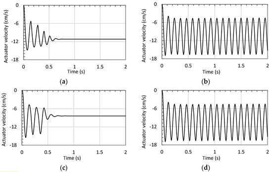
Figure 11.
Simulation results of the velocity responses in the critical zone for the conventional circuit with shuttle valve (Figure 7). (a) Actuator velocity responses versus time at test point TP1 (FL = 3870 N); (b) actuator velocity responses at test point TP2 (FL = 3100 N); (c) actuator velocity responses at test point TP3 (FL = 2220 N); (d) construction of critical region.
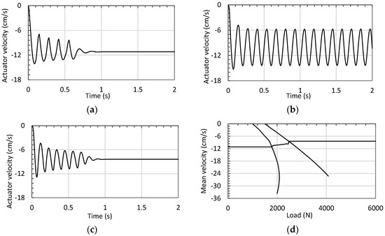
Figure 12.
Simulation results of the velocity responses in the critical zone for the proposed circuit with shuttle valve (Figure 2). (a) Actuator velocity responses versus time at test point TP (FL = 2470 N); (b) actuator velocity responses at test point TP (FL = 2000 N); (c) actuator velocity responses at test point TP (FL = 1700 N); (d) construction of critical region.
Figure 13 shows velocity oscillation amplitudes at different loads in the original and proposed circuits. Simulations were conducted at a control signal of −4 V and a load margin from 0 to 6000 N, thus covering critical zones in both circuits. It is clear from figure that the size of the critical zone in the proposed circuit reduced in both width and amplitude and further shifted towards a lower loading margin as compared to that of the original circuit. The critical zone width was 1650 N and 770 N with maximum velocity amplitudes of 5.8 cm/s and 4.4 cm/s in the original and proposed circuits, respectively.
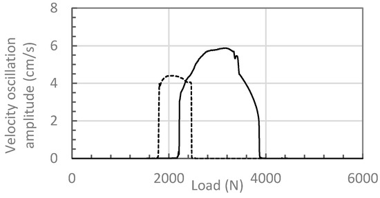
Figure 13.
Simulation results for the velocity oscillation amplitudes versus the load for the previously designed (solid line) and proposed (dashed line) circuits that use shuttle valves.
The simulation studies clearly show that the critical zone size reduced by 50% and the maximum amplitude of actuator velocity oscillations reduced by 24% in the proposed circuit. From the rated energy point of view, the maximum rated energies at oscillatory points TP2 and TP were 3100 N × 0.168 m/s = 520.8 W and 2000 N × 0.14 m/s = 280 W for the original and proposed circuits, respectively.
4. Experimental Evaluations
Figure 14a,b illustrate a photo and the schematic of the test rig used to perform the experimental studies. The test rig comprises a JD-48 John Deere backhoe attachment, electrically controlled variable-displacement pump, a charge pressure unit, shuttle valves, and instrumentations. Figure 14c shows the calculated static load at the actuator rod for a 368 kg attached mass. Note that experiments were only conducted for circuits with SHVs using in-house built components.
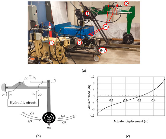
Figure 14.
(a) Test rig and main components: (1) JD-48 backhoe structure; (2) main pump unit; (3) charge pump unit; (D) displacement sensor; (PS) pressure sensor; (SHV) shuttle valves. (b) Schematic drawing. (c) Calculated static load at the actuator rod, FL, for a 368kg attached mass.
Specifications of the main components of the test rig are listed in Table 2. Since the proposed 4/3 biased shuttle valve is not commercially available, we utilized an in-house modified biased version of a 3/3 shuttle valve and one charge pressure. Experiments were conducted for circuits with CC-SHVs and circuits with OC-SHVs. Two sets of experiments were conducted for each circuit. The first set of experiments was performed on the circuit equipped with the conventional 3/3 CC-SHV and the circuit with the modified biased CC-SHV. As shown in Figure 15, the balancing spring in the valve was installed on one side of the spool in a way that it resembles two springs on both sides of the spool. The SHV was modified by adding one extra spring at the free end of the spool, which was connected to line A of the circuit, in order to obtain a biased position of the spool. The modified SHV had equal spool piloting areas and different stiffness of balancing springs at both sides of the spool with a ratio equal to actuator area ratio i.e., = = 0.75. Applying this condition, when using a 170 psi charge pressure, an extra spring with a stiffness and pre-compression length equivalent to 50 psi was added on side A of the valve (Figure 15). The second set of experiments was conducted on circuits equipped with conventional and modified OC-SHVs. The valve was modified in a similar way to that of the CC-SHV. All experiments were performed using a square input signal applied to control the pump swash plate in an open-loop configuration.

Table 2.
Specifications of test rig.

Figure 15.
Modified closed-center shuttle valve (a) exploited parts; (b) schematic drawing.
Figure 16 shows the responses of the circuits equipped with the conventional and modified CC-SHV, side-by-side. Figure 16a,b illustrate the input control signals, which are manually applied for safety reasons. Small differences between input signals are attributed to the human factor. Figure 16c,d show the actuator velocity and Figure 16e,f display the pressure responses for the circuits with the conventional and biased SHVs, respectively.

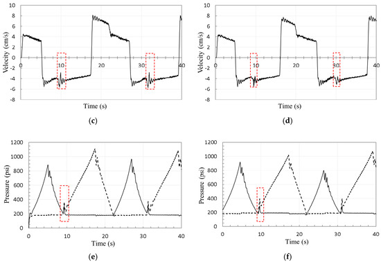
Figure 16.
Experimental performance of the original (left column) and proposed (right column) circuits with closed-center shuttle valves, respectively, for a 810 lb (368 kg) attached mass: (a,b) control signals; (c,d) actuator velocity; (e,f) pressures at pump ports a (solid line) and b (dashed line).
It is clear from the results that both circuits face oscillatory behavior when switching from motoring to pumping modes during actuator retraction, at times from 9 s to 12 s and from 30 s to 33 s. The velocity graphs show that the maximum velocity oscillation amplitudes are 2.8 cm/s and 1.9 cm/s in the conventional and modified circuits, respectively. However, it is noticed that the oscillations lasted less in the modified circuit as compared to those related to conventional circuit.
Figure 17 shows the responses of the circuits that utilize the conventional and modified OC-SHV, respectively. Figure 17a,b illustrate the manually applied control signals to the corresponding circuits. Figure 17c,d display the actuator velocity responses and Figure 17e,f show the pressure responses of the circuits equipped with the conventional and conventional OC-SHVs, respectively.
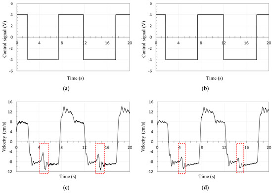
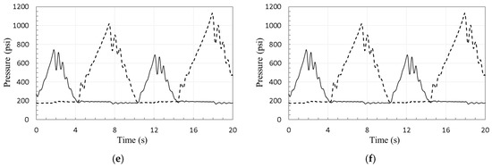
Figure 17.
Experimental performance of the original (left column) and proposed (right column) circuits with open-center shuttle valves, respectively, for a 810 lb (368 kg) attached mass: (a,b) control signals; (c,d) actuator velocity; (e,f) pressures at the pump ports a (solid line) and b (dashed line).
It can be seen from the velocity and pressure responses that both circuits experience oscillations when switching from motoring to pumping modes during actuator retraction at times from 4 s to 6 s and from 14 s to 16 s. The maximum velocity oscillation amplitudes are 7.1 cm/s and 4.6 cm/s in the conventional and modified circuits, respectively, which indicates a 35% reduction in the oscillation amplitude. It is also noticed that the oscillations continued for a shorter period of time in the modified circuit compared to that of the conventional circuit. Lastly, experimental studies verified that the modified circuits caused a considerable reduction in the duration and amplitudes of the reported system oscillations of the conventional pump-controlled circuits.
5. Conclusions
In this paper, a new approach to deal with the undesirable velocity oscillations of certain classes of pump-controlled hydraulic circuits for single-rod actuators is proposed. In this approach, the critical zone is shifted towards a lower loading range by utilizing: (i) two charge pressures, and (ii) asymmetric compensating valves. This approach is applicable to the available solutions that utilize pilot-operated check valves or shuttle valves. Simulation studies proved the effectiveness of the concept in reducing the size of the undesirable zone and the severity of the oscillations. Experimental studies were conducted by utilizing circuits with two types of shuttle valves. The results show that the size of the critical zone and the maximum amplitude of the actuator velocity oscillations reduced by 50% and 30%, respectively, as compared to previously proposed designs. We conclude that the proposed approach enhances the performance of already existing circuits by alleviating system oscillations and reducing fatiguing effects of velocity oscillations on machine components.
Author Contributions
Conceptualization, A.I. and N.S.; Data curation, A.I. and M.R.; Formal analysis, A.I.; Investigation, A.I. and M.R.; Methodology, A.I. and T.Z.; Software, A.I.; Supervision, N.S.; Validation, A.I.; Writing—original draft, A.I. and M.R.; Writing—review & editing, A.I. and N.S.
Acknowledgments
The authors would like to thank the Natural Sciences and Engineering Research Council (NSERC) of Canada for providing financial support for this research.
Conflicts of Interest
The authors declare no conflict of interest. The founding sponsors had no role in the design of the study; in the collection, analyses, or interpretation of data; in the writing of the manuscript, and in the decision to publish the results.
References
- Ritelli, G.F.; Vacca, A. Energetic and dynamic impact of counterbalance valves in fluid power machines. Energy Convers. Manag. 2013, 76, 701–711. [Google Scholar] [CrossRef]
- Zemmerman, J.D.; Pelosi, M.; Williamson, C.A.; Ivantysynova, M. Energy consumption of an LS excavator hydraulic system. In Proceedings of the ASME International Mechanical Engineering Congress and Exposition (IMECE), Seattle, WA, USA, 11–15 November 2007; pp. 117–126. [Google Scholar]
- Imam, A.; Rafiq, M.; Jalayeri, E.; Sepehri, N. Design, implementation and evaluation of a pump-controlled circuit for single rod actuators. Actuators 2017, 6, 10. [Google Scholar] [CrossRef]
- Cleasby, K.G.; Plummer, A.R. A novel high efficiency electrohydrostatic flight simulator motion system. In Proceedings of the Symposium on Fluid Power and Motion Control (FPMC 2008), Bath, UK, 10–12 September 2008; pp. 437–449. [Google Scholar]
- Zimmerman, J.D. Toward Optimal Multi-Actuator Displacement Controlled Mobile Hydraulic Systems. Ph.D. Thesis, Purdue University, West Lafayette, IN, USA, 2012. [Google Scholar]
- Imam, A.; Rafiq, M.; Jalayeri, E.; Sepehri, N. A pump-controlled circuit for single-rod cylinders that incorporates limited throttling compensating Valves. Actuators 2018, 7, 13. [Google Scholar] [CrossRef]
- Li, J.; Fu, Y.; Wang, Z.; Zhang, G. Research on fast response and high accuracy control of an airborne electro hydrostatic actuation system. In Proceedings of the 2004 International Conference on Intelligence, Mechatronics and Automotion, Changdu, China, 26–31 August 2004. [Google Scholar]
- Bossche, D. The A380 flight control electrohydrostatic actuators, achievements and lessons learnt. In Proceedings of the 25th International Congress of Aeronautical Sciences, Hamburg, Germany, 3–8 September 2006. [Google Scholar]
- Hewett, A. Hydraulic Circuit Flow Control. U.S. Patent 5,329,767, 19 July 1994. [Google Scholar]
- Ivantysynova, M. The swash plate machine for displacement control unit with great development potentiality. In Proceedings of the First International Fluid Technology Colloqium (IFK), Aachen, Germany, 17–18 March 1998. [Google Scholar]
- Wang, L.; Book, W.J.; Huggins, J.D. A hydraulic circuit for single rod cylinder. J. Dyn. Syst. Meas. Control ASME 2012, 134, 011019. [Google Scholar] [CrossRef]
- Jalayeri, E.; Imam, A.; Zeljko, T.; Sepehri, N. A throttle-less single-rod hydraulic cylinder positioning system: Design and experimental evaluation. Adv. Mech. Eng. 2015, 7, 1–14. [Google Scholar] [CrossRef]
- Caliskan, H.; Balkan, T.; Platin, B.E. A complete analysis and a novel solution for instability in pump controlled asymmetric actuators. J. Dyn. Syst. Meas. Control 2015, 137, 091008. [Google Scholar] [CrossRef]
- Rahmfeld, R.; Ivantysynova, M. Displacement controlled linear actuator with differential cylinder—A way to save primary energy in mobile machines. In Proceedings of the 5th International Conference on Fluid Power Transmission and Control (ICFP’2001), Hangzhou, China, 3–5 April 2001. [Google Scholar]
- Williamson, C.; Ivantysynova, M. Pump mode prediction for four-quadrant velocity control of valveless hydraulic actuators. In Proceedings of the 7th JFPS International Symposium on Fluid Power, Toyama, Japan, 15–18 September 2008; pp. 323–328. [Google Scholar]
- Michel, S.; Weber, J. Electrohydraulic compact-drives for low power applications considering energy-efficiency and high inertial loads. In Proceedings of the 7th FPNI PhD Symposium on Fluid Power, Reggio Emilia, Italy, 27–30 June 2012; pp. 869–888. [Google Scholar]
- MathWorks. Available online: https://www.mathworks.com/help/physmod/hydro/ref/cylinderfriction.html?requestedDomain=www.mathworks.com (accessed on 1 December 2018).
- Williamson, C. Power Management for Multi-Actuator Mobile Machines with Displacement Controlled Hydraulic. Ph.D. Thesis, University of Purdue, West lafayette, IN, USA, 2010. [Google Scholar]
- Merritt, H.E. Hydraulic Control Systems; John Wily and Sons: New York, NY, USA, 1967. [Google Scholar]
© 2019 by the authors. Licensee MDPI, Basel, Switzerland. This article is an open access article distributed under the terms and conditions of the Creative Commons Attribution (CC BY) license (http://creativecommons.org/licenses/by/4.0/).