On Hirth Ring Couplings: Design Principles Including the Effect of Friction
Abstract
1. Introduction
- ○
- accuracy, in terms of relative positioning between the parts connected together;
- ○
- stiffness of the system, thanks to the steady self-center geometry of the teeth;
- ○
- power, in terms of torque transmission;
- ○
- resistance to wear, thanks to a wide support surface of the teeth and the use of special alloyed steels.
2. Standard Calculation
3. Improved Calculation
3.1. Effect of Friction
3.2. Self-Centering Capability
4. Experimental Tests
5. Case Study
- The condition of the minimum torque T to be transmitted (ID8) is satisfied with the requested safety factor (SF = 4, ID11): 15,750 Nm > 3500 Nm (ID21 > ID8). The same condition also applies (obviously) to the tangential forces Fu: 35,000 N > 7778 N (ID13 > ID10).
- The axial force Fa required for the transmission of the torque is 30,965 N (ID14): it is granted by a hydraulic piston (upon setting the pressure level of the oil, this force is fixed).
- The frictional force Rμ, depending on the weight of the rotary table (40,000 N, ID16) and on the coefficient of friction (~0.2, ID5), is 8138 N. The self-centering capability is verified since the condition Fc > Rμ is satisfied (22,326 N > 8138 N, ID15 > ID17).
- The accuracy of the angular positioning is also verified. The friction torque on the bearing surface of the rotating ring, which depends on the frictional force Rμ, on the mean sliding radius (ID18) and on the coefficient of friction (ID5), is 3825 Nm; the additional frictional torque for the rotating elements (such as rotary sealings for oil distribution, bearings and gears) is 3000 Nm (ID20). The torque T that the Hirth connection is able to provide proves to be higher than the total frictional torque Tμ: 15,750 Nm > 6825 Nm (ID21 > ID22).
6. Closed-Form Determination of a Friction Threshold to Ensure Self-Centering
7. Conclusions
Author Contributions
Conflicts of Interest
Nomenclature
| Az | Effective tooth flank area (mm2) |
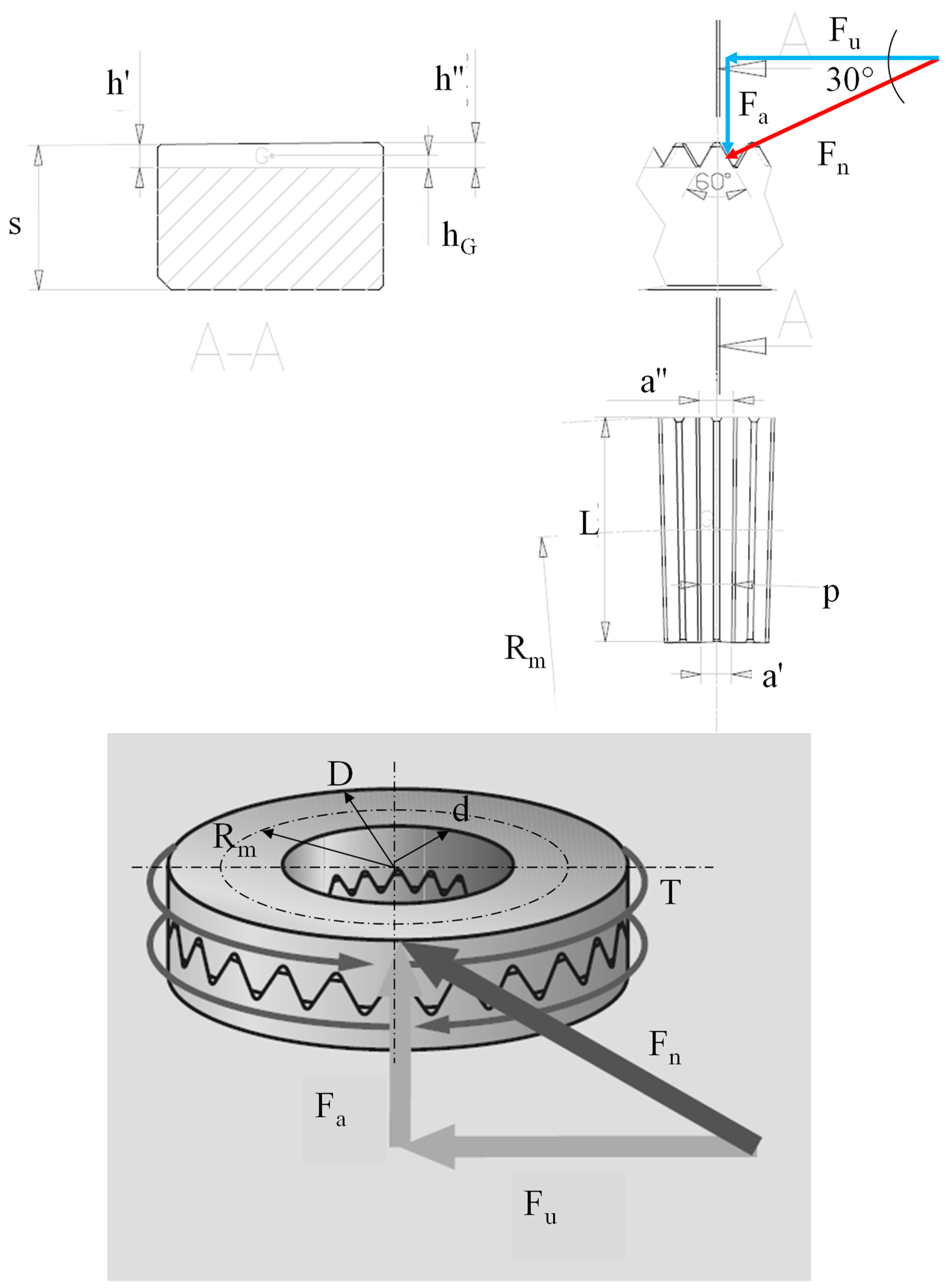
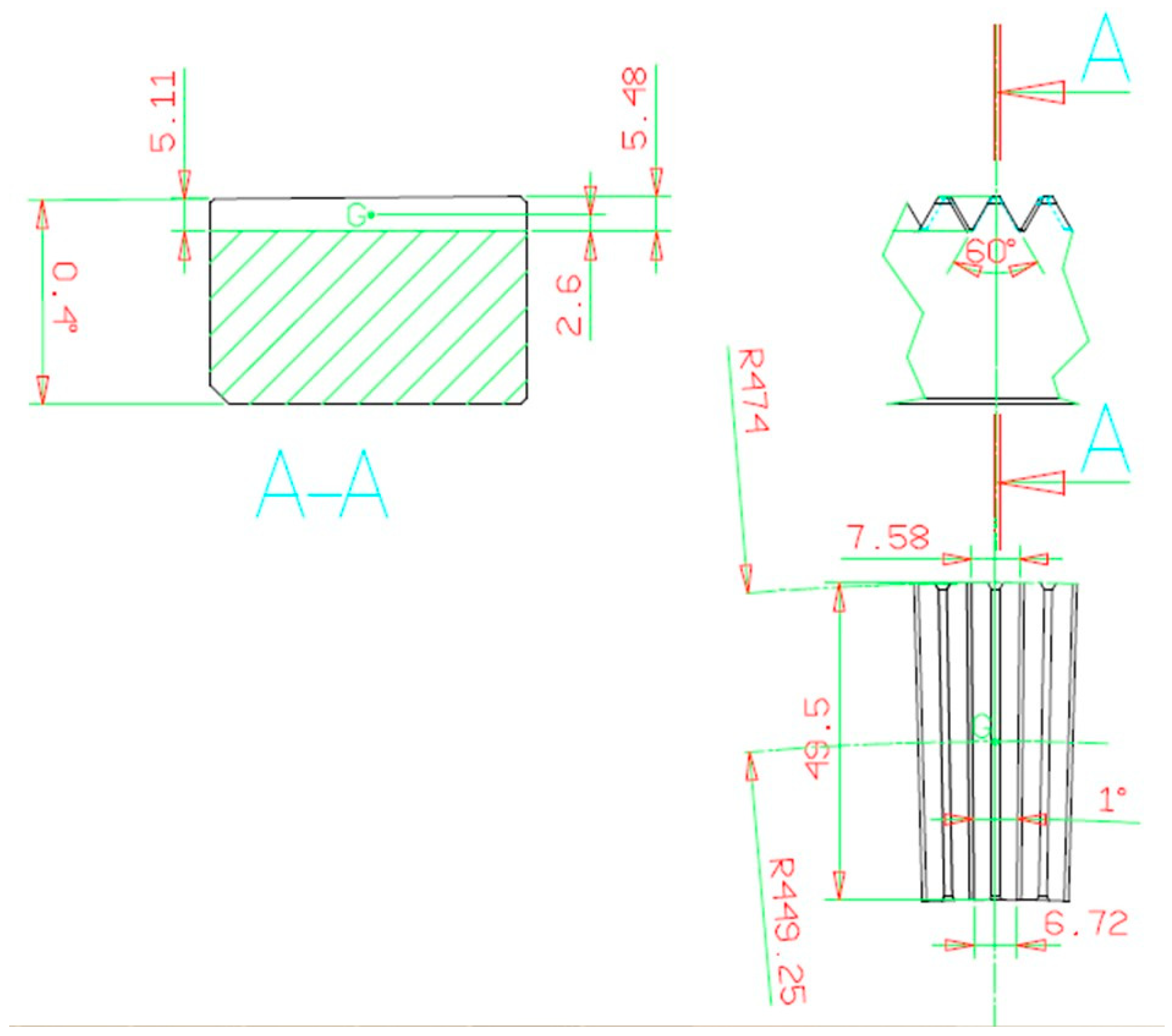
| a’, a”, hG | Geometrical features of the Hirth ring and related teeth (from Figure 3) |
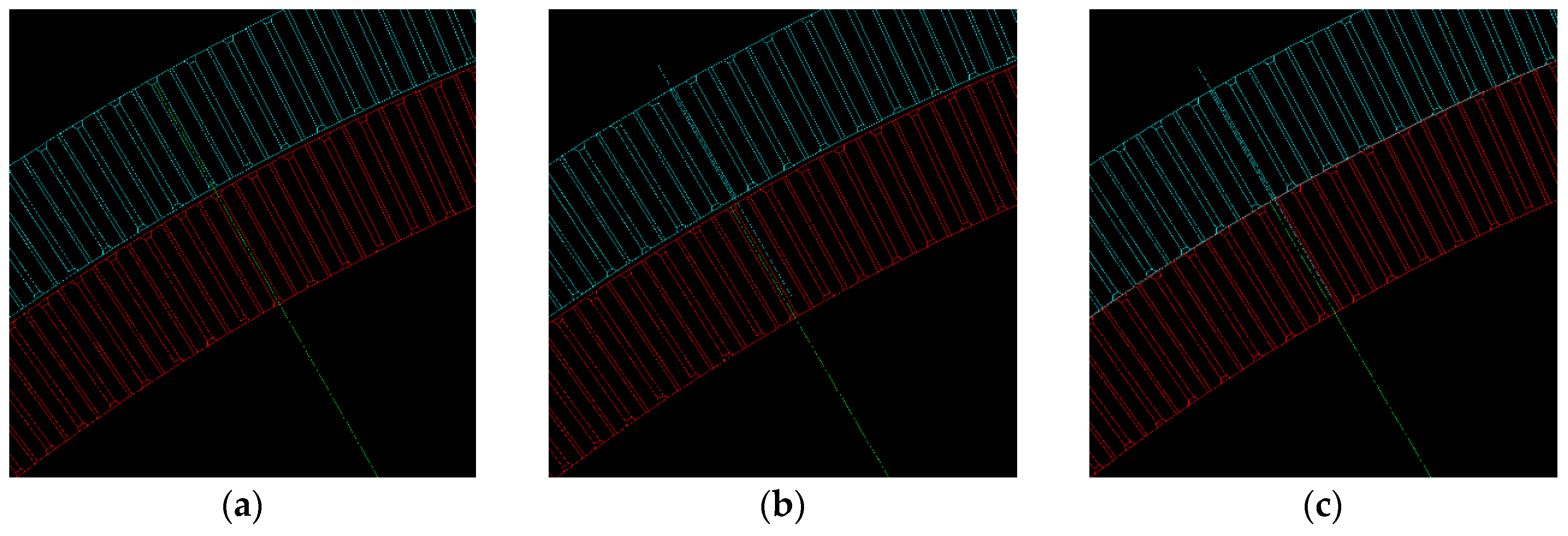
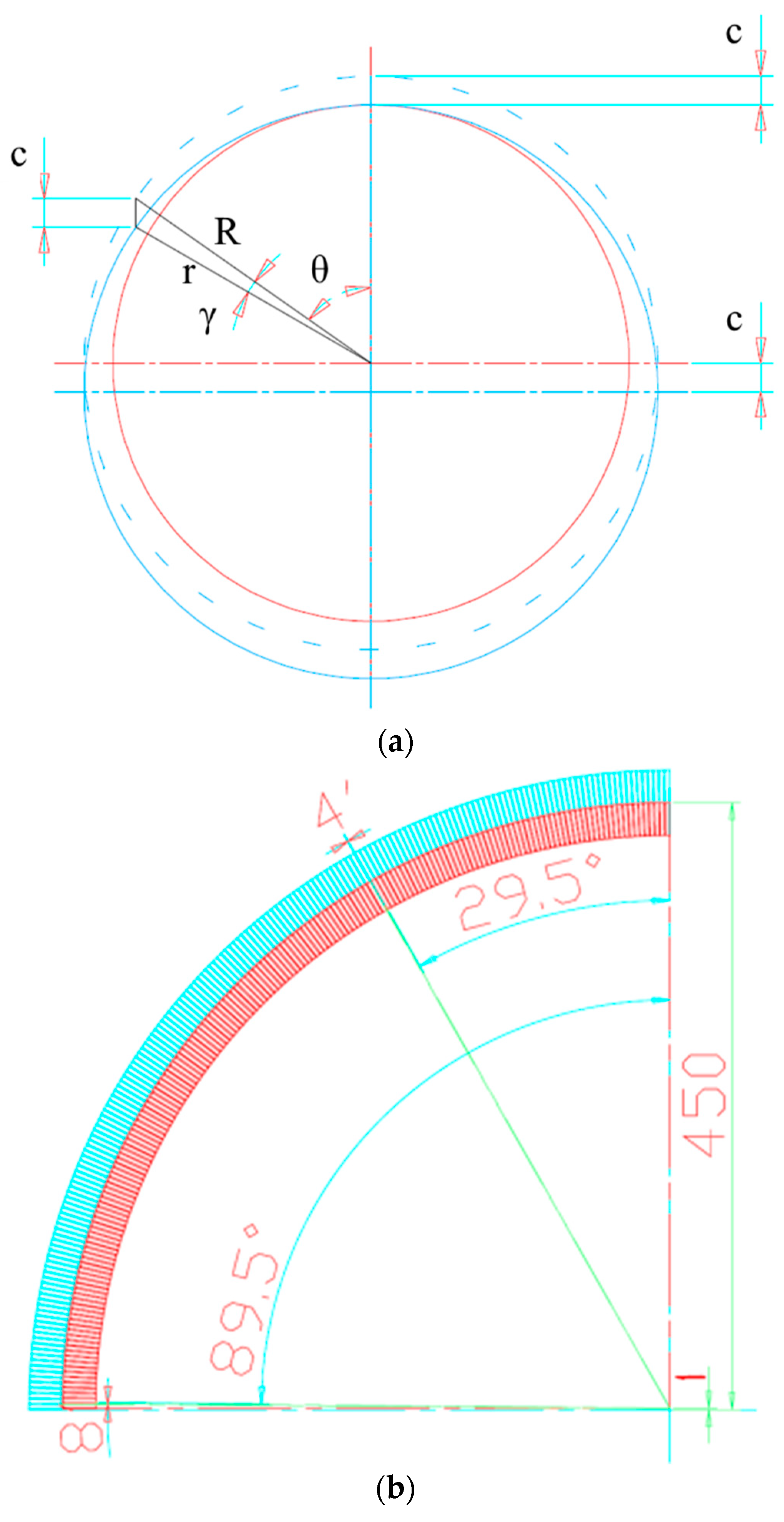
| c | Center misalignment between the fixed and the rotating rings (mm) |
| cmax | Maximum center misalignment between the fixed and the rotating rings (mm) |
| D | Outer diameter of the teeth (mm) |
| d | Inner diameter of the teeth (mm) |
| dL | Fixing hole diameter (mm) |
| Factor c | Factor depending on the number of teeth z (from Table 2) |
| Fa | Axial force generated by the Hirth coupling (N, kN) |
| Fc | Self-centering force (N, kN) |
| Fr,e | Additional external force in the radial direction (experimental validation test) (N) |
| FS | Safety factor for the total tangential force (-) |
| Fu | Total tangential force (N, kN) |
| Fu,μ | Actual tangential force (including friction) (N, kN) |
| Fν-a | Preload (N, kN), considering a safety factor ν |
| h | Tooth height (mm) |
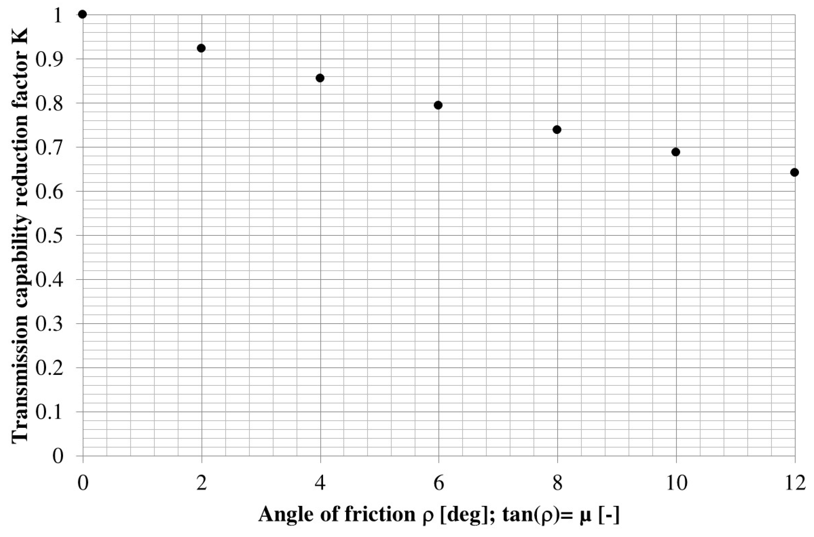
| K | Reduction factor for the transmitted load (-) |
| KC | Coefficient for the self-centering force computation, depending on the number of teeth |
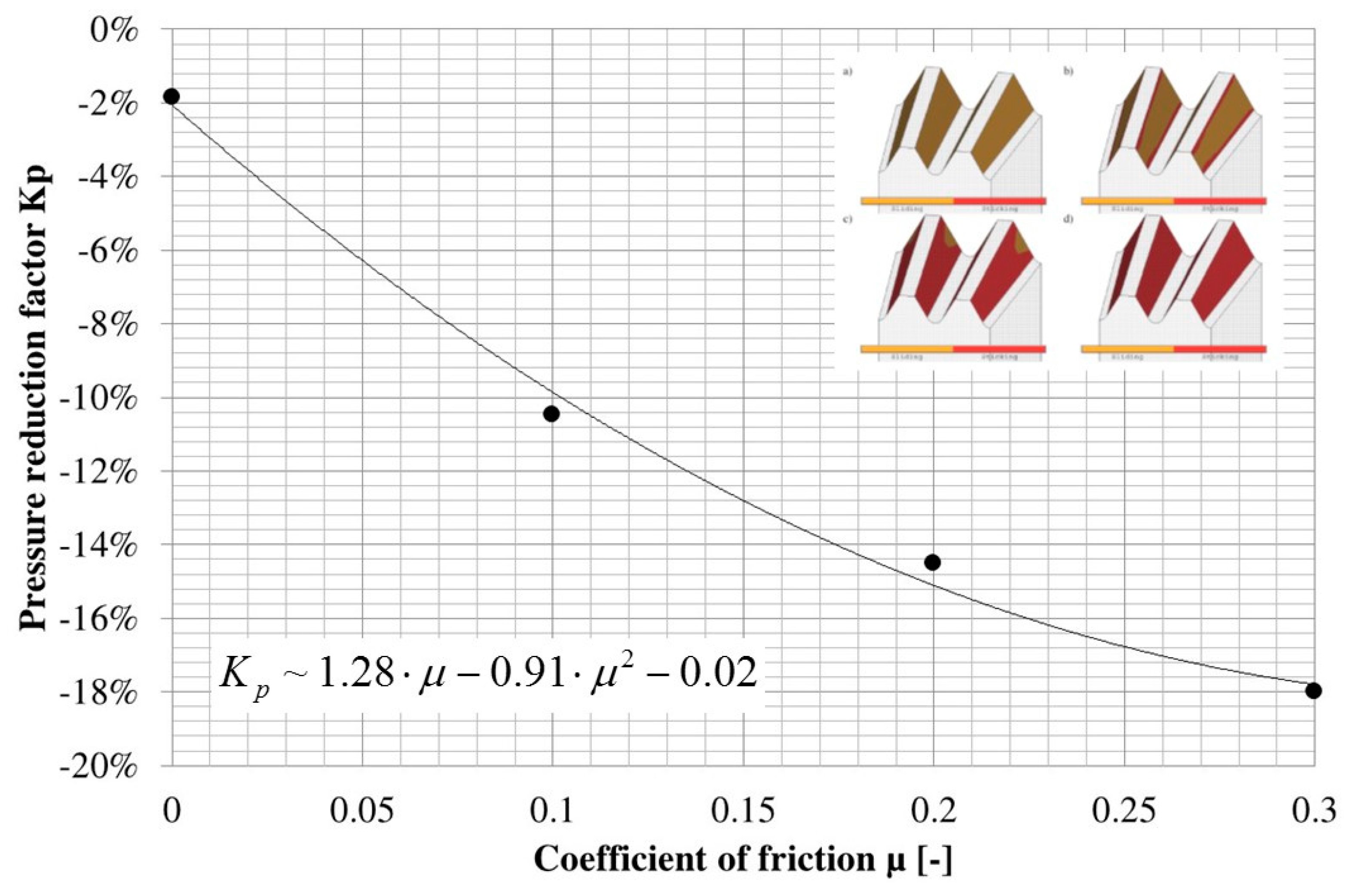
| Kp | Percentage reduction factor for the tooth pressure (%) |
| nb | Number of bolts in the teeth surface |
| pmax | Maximum pressure on tooth flank (MPa) |
| R | Ring diameter (mm) |
| Rm | Mean radius of the ring (mm) |
| Rμ | Frictional resistance force (N, kN) |
| r | Tooth base radius (mm) |
| s | Crown clearance (mm) |
| T | External torque to be transmitted (Nm, Nmm) |
| Tµ | Frictional torque (Nm, Nmm) |
| W | Overall weight to be moved upon self-centering (N, kN) |
| z | Number of teeth (-) |
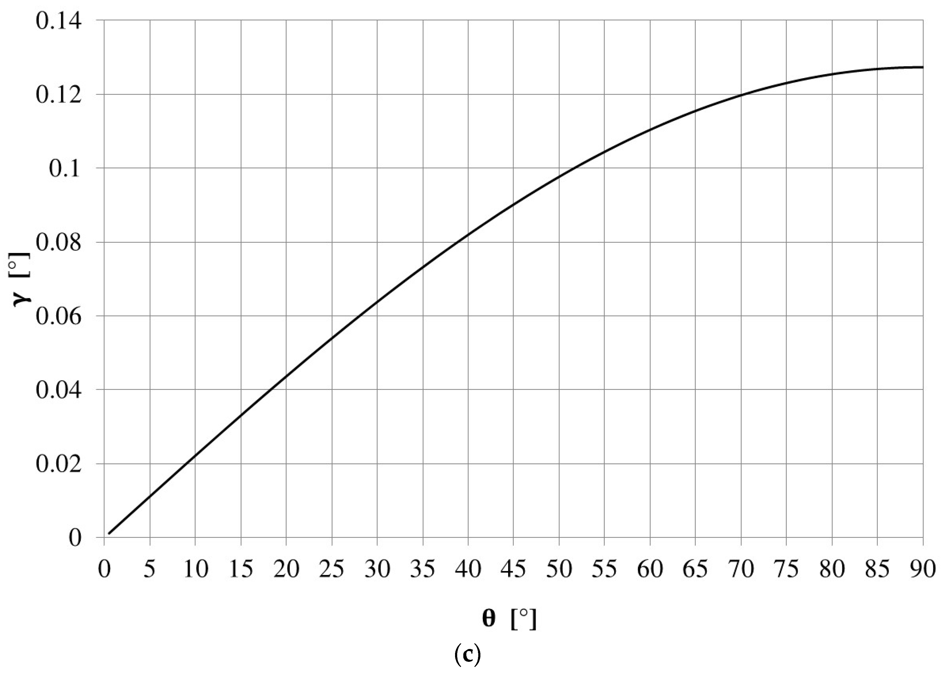
| γ | Angular misalignment between the fixed and the rotating rings (°) |
| γmax | Maximum angular misalignment between the fixed and the rotating rings (°) |
| ηz | Load bearing percentage (-) |
| μ | Coefficient of friction (-) |
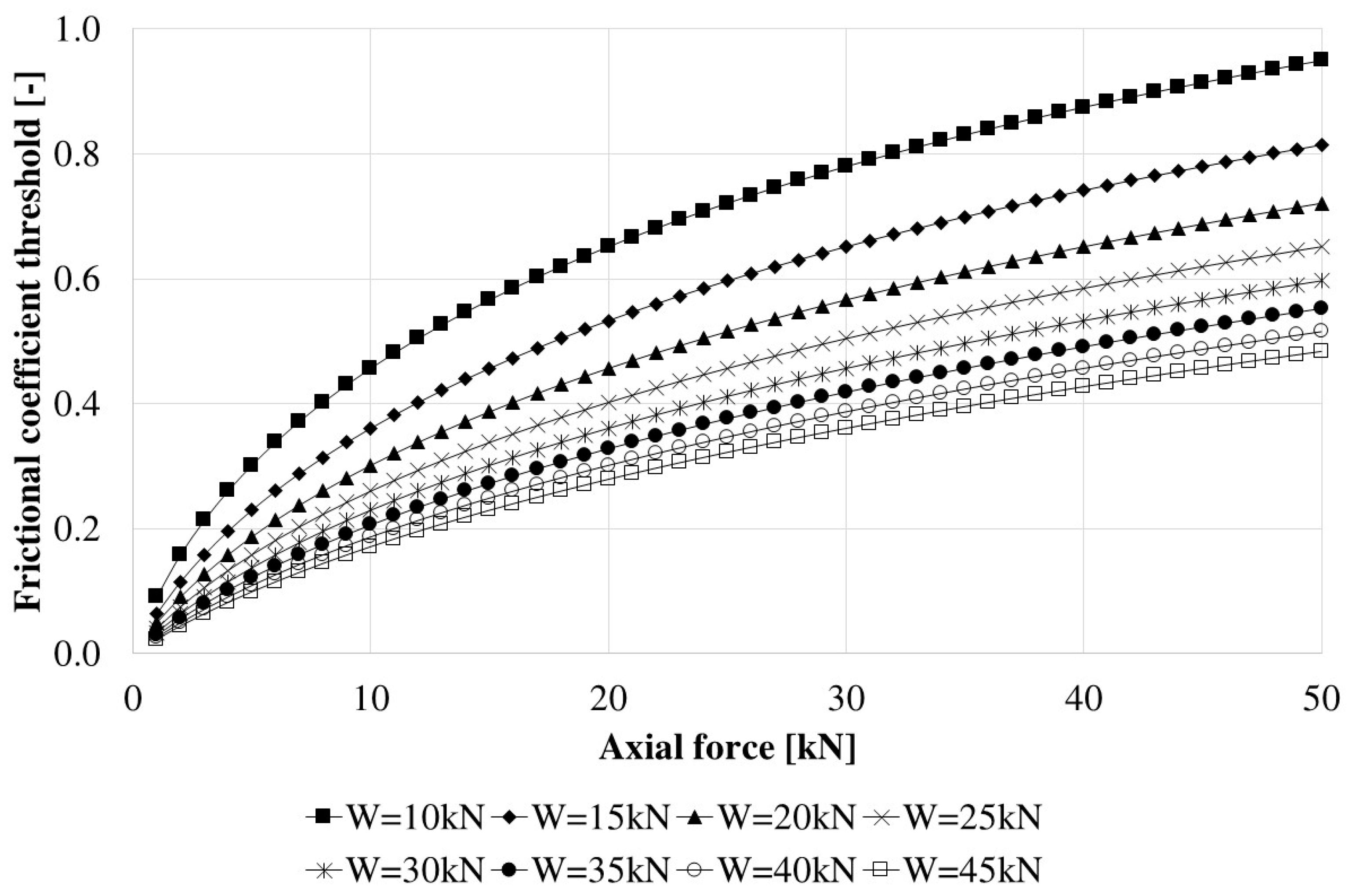
| μth | Coefficient of friction upper threshold to achieve self-centering (-) |
| ν | Safety factor for preload (-) |
| θ | General angular coordinate over the Hirth ring (°) |
| ρ | Angle of friction (°, rad) |
| σb | Tooth bending normal stress (MPa) |
| σb_ref | Allowable normal stress (MPa) |
| τ | Shear stress due to the transmitted torque (MPa) |
| τ_ref | Allowable shear stress (MPa) |
References
- Hirth, C.A. Shaft Coupling. U.S. Patent 1,660,792, 28 February 1928. [Google Scholar]
- Yuan, S.X.; Zhang, Y.Y.; Zhang, Y.C.; Jiang, X.J. Stress distribution and contact status analysis of a bolted rotor with curvic couplings. Proc. I. Mech. Eng. C-J. Mec. 2010, 224, 1815–1829. [Google Scholar] [CrossRef]
- Pisani, S.R.; Rencis, J.J. Investigating CURVIC coupling behavior by utilizing two- and three-dimensional boundary and finite element methods. Eng. Anal. Bound. Elem. 2000, 24, 271–275. [Google Scholar] [CrossRef]
- Richardson, I.J.; Hyde, T.H.; Becker, A.A.; Taylor, J.W. A validation of the three-dimensional finite element contact method for use with curvic couplings. Proc. Inst. Mech. Eng. G-J. Aerosp. Eng. 2002, 216, 63–275. [Google Scholar] [CrossRef]
- Richardson, I.J.; Hyde, T.M.; Becker, A.A.; Taylor, J.W. A three-dimensional finite element investigation of the bolt stresses in an aero-engine curvic coupling under a blade release condition. Proc. Inst. Mech. Eng. G-J. Aerosp. Eng. 2000, 214, 231–245. [Google Scholar] [CrossRef]
- Yin, Z.Y.; Hu, B.A.; Wu, J.G.; Xu, Y.L.; Zheng, Q.X. Calculation of axial relaxed/pressed forces of rotors with curvic couplings. Acta Aeronaut. Aeronaut. Sin. 1996, 17, 555–560. [Google Scholar]
- Hu, B.A.; Yin, Z.Y.; Xu, Y.L. Determination of axial preloads of rotor with curvic couplings pretightened into two segments. J. Mech. Strength 1999, 21, 274–277. [Google Scholar]
- Croccolo, D.; Cavalli, O.; De Agostinis, M.; Fini, S.; Olmi, G.; Robusto, F.; Vincenzi, N. A Methodology for the Lightweight Design of Modern Transfer Machine Tools. Machines 2018, 6, 2. [Google Scholar] [CrossRef]
- Cao, H.; Li, D.; Yue, Y. Root Cause Identification of Machining Error Based on Statistical Process Control and Fault Diagnosis of Machine Tools. Machines 2017, 5, 20. [Google Scholar]
- Zhang, F.P.; Lu, J.P.; Tang, S.Y.; Sun, H.F.; Jiao, L. Locating error considering dimensional errors modeling for multistation manufacturing system. Chin. J. Mech. Eng. 2010, 23, 765–773. [Google Scholar] [CrossRef]
- Du, C.; Zhang, J.; Lu, D.; Zhang, H.; Zhao, W. A parametric modeling method for the pose-dependent dynamics of bi-rotary milling head. Proc. Inst. Mech. Eng. B-J. Eng. Manuf. 2018, 232, 797–815. [Google Scholar] [CrossRef]
- Liu, X.; Yuan, Q.; Liu, Y.; Gao, J. Analysis of the stiffness of hirth couplings in rod-fastened rotors based on experimental modal parameter identification. In Proceedings of the ASME Turbine Technical Conference and Exposition, Düsseldorf, Germany, 16–20 June 2014. [Google Scholar]
- Du, C.; Zhang, J.; Lu, D.; Zhang, H.; Zhao, W. Coupled Model of Rotary-Tilting Spindle Head for Pose-Dependent Prediction of Dynamics. J. Manuf. Sci. Eng. 2018, 140, 081008. [Google Scholar] [CrossRef]
- Matzke, G. Verbindung von Wellen durch Verzahnung. Konstruktion 1951, 3, 211–216. [Google Scholar]
- Croccolo, D.; De Agostinis, M.; Fini, S.; Olmi, G. Tribological properties of bolts depending on different screw coatings and lubrications: An experimental study. Tribol. Int. 2017, 107, 199–205. [Google Scholar] [CrossRef]
- Croccolo, D.; De Agostinis, M.; Vincenzi, N. A contribution to the selection and calculation of screws in high duty bolted joints. Int. J. Pres. Ves. Pip. 2012, 96, 38–48. [Google Scholar] [CrossRef]
- Croccolo, D.; De Agostinis, M.; Vincenzi, N. Influence of tightening procedures and lubrication conditions on titanium screw joints for lightweight applications. Tribol. Int. 2012, 55, 68–76. [Google Scholar] [CrossRef]
- Croccolo, D.; De Agostinis, M.; Fini, S.; Olmi, G. An experimental study on the response of a threadlocker, involving different materials, screw dimensions and thread proportioning. Int. J. Adhes. 2018, 83, 116–122. [Google Scholar] [CrossRef]
- Croccolo, D.; Vincenzi, N. Tightening tests and friction coefficients definition in the steering shaft of front motorbike suspension. Strain 2011, 47, 337–342. [Google Scholar] [CrossRef]
- Niemann, G.; Winter, H.; Hohn, B.R. Maschinenelemente; Springer-Verlag: Berlin, Germany, 2005. [Google Scholar]
- Croccolo, D.; De Agostinis, M.; Vincenzi, N. Normalization of the stress concentrations at the rounded edges of a shaft-hub interference fit: Extension to the case of a hollow shaft. J. Strain Anal. Eng. 2012, 47, 131–139. [Google Scholar] [CrossRef]
- Croccolo, D.; De Agostinis, M.; Fini, S.; Morri, A.; Olmi, G. Analysis of the influence of fretting on the fatigue life of interference fitted joints. In Proceedings of the ASME International Mechanical Engineering Congress and Exposition, Montreal, QC, Canada, 14–20 November 2014; Volume 2B, p. V02BT02A008. [Google Scholar] [CrossRef]
- Jiang, X.J.; Zhang, Y.Y.; Yuan, S.X. Analysis of the contact stresses in curvic couplings of gas turbine in a blade-off event. Strength Mater. 2012, 44, 539–550. [Google Scholar] [CrossRef]
- Croccolo, D.; Cuppini, R.; Vincenzi, N. Friction coefficient definition in compression-fit couplings applying the DOE method. Strain 2008, 44, 170–179. [Google Scholar] [CrossRef]
- RR71, Friction in Temporary Works, ISBN 0 7176 2613 X, HSE Books. Available online: http://www.hse.gov.uk/research/rrhtm/rr071.htm (accessed on 19 November 2018).






| Type of Stress | Carbon Steel | Alloyed Steel Cr-Ni and Cr-Mo | ||
|---|---|---|---|---|
| σb_ref (MPa) | τ_ref (MPa) | σb_ref (MPa) | τ_ref (MPa) | |
| No Shocks | 90 | 33.5 | 120 | 44.5 |
| With shocks | 50 | 18.5 | 70 | 26 |
| With shocks and with torsional vibration | 35 | 13 | 50 | 18.5 |
| Number of Teeth z | Factor c |
| 12 | 0.234 |
| 24 | 0.114 |
| 36 | 0.075 |
| 48 | 0.056 |
| 60 | 0.045 |
| 72 | 0.037 |
| 96 | 0.028 |
| 120 | 0.022 |
| 144 | 0.018 |
| 180 | 0.015 |
| 240 | 0.011 |
| 288 | 0.009 |
| 360 | 0.007 |
| 720 | 0.003 |
| Tooth Root Radius r | Crown Clearance s |
| 0.3 | 0.4 |
| 0.6 | 0.6 |
| 1.0 | 1.0 |
| 1.6 | 1.6 |
| 2.5 | 2.5 |
| Control | Theoretical Measures | Tolerance | Results | |
|---|---|---|---|---|
| ∅ ext. | C1 | |||
| C2 | 990 mm | −0.01 to −0.03 mm | 989.971 mm | |
| C3 | ||||
| ∅ ext. Circularity | C1 | |||
| C2 | 0.005 mm | |||
| C3 | ||||
| ∅ int. | C1 | 849 mm H7 | +0.090 mm | 849.018 mm |
| C2 | ||||
| C3 | 829 mm | +0.030 mm | 829.017 mm | |
| ∅ int. Circularity | C1 | 0.004 mm | ||
| C2 | ||||
| C3 | 0.004 mm | |||
 Concentricity ∅ int.- ∅ ext. | C1 |  | 0.003 mm | |
| C2 |  | 0.004 mm | ||
| C3 |  | 0.003 mm | ||
 Flatness | C1 | 0.003 mm | ||
| C2 | 0.002 mm | |||
| C3 | 0.002 mm | |||
 Parallelism C1-C2 Rotating C2 | 0° | 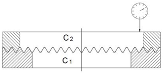 | 0.007 mm | |
| 90° | 0.009 mm | |||
| 180° | 0.008 mm | |||
| 270° | 0.009 mm | |||
 Parallelism C1-C3 Rotating C3 | 0° | 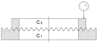 | 0.008 mm | |
| 90° | 0.009 mm | |||
| 180° | 0.006 mm | |||
| 270° | 0.009 mm | |||
 Concentricity C1-C2 Rotating C2 | 0° |  | 0.008 mm | |
| 90° | 0.009 mm | |||
| 180° | 0.006 mm | |||
| 270° | 0.009 mm | |||
 Concentricity C1-C3 Rotating C3 | 0° |  | 0.007 mm | |
| 90° | 0.009 mm | |||
| 180° | 0.008 mm | |||
| 270° | 0.009 mm | |||
| Indexing accuracy | 1.50’’ | |||
| Hardness | HRC 54 | ±2 (HRC) | HRC 54 | |
| Additional External Radial Load Fr,e (N) | Self-Centering Capability (YES/NO) |
|---|---|
| 20 | YES  |
| 40 | YES  |
| 60 | YES  |
| 80 | YES  |
| 100 | YES  |
| 120 | NO  |
| ID | Description | Type of Data | Value | Units |
|---|---|---|---|---|
| 1 | Tooth Angle | Input data (fixed for Hirth connection) | 30 | ° |
| 2 | 0.524 | rad | ||
| 3 | Friction angle | Input data | 11.5 | ° |
| 4 | 0.201 | rad | ||
| 5 | Coefficient of friction µ | Calculated: µ = tan(ρ) | 0.203 | |
| 6 | Maximum external tangential force to be transmitted during a milling operation | Input data | 5000 | N |
| 7 | Distance from the center of the tangential force (radius of the rotary table) | Input data | 700 | mm |
| 8 | Minimum Torque T to be transmitted | Calculated: ID6 × ID7 | 3500 | Nm |
| 9 | Hirth rings mean radius | Input data | 450 | mm |
| 10 | Tangential force Fu on the Hirth connection | Calculated: ID8 × 1000/ID9 | 7778 | N |
| 11 | Safety factor SF | Input data (reference value: 3 … 5) | 4 | |
| 12 | Tangential force Fu on the Hirth connection including SF | Calculated: ID10 × ID11 | 31,111 | N |
| 13 | Tangential force Fu used for the design | Selected by the designer on the basis of ID12 | 35,000 | N |
| 14 | Axial force Fa (including friction) | Calculated (info in the paper) | 30,965 | N |
| 15 | Self-centering capability Fc | Calculated (info in the paper) | 22,326 | N |
| 16 | Weight of the rotary table connected to the rotary ring | Input data | 40,000 | N |
| 17 | Frictional force Rµ | Calculated: ID16 × ID5 | 8138 | N |
| 18 | Mean sliding radius of the bearing surface | Input data | 470 | mm |
| 19 | Frictional torque on the bearing surface | Calculated: ID17 × ID18 | 3825 | Nm |
| 20 | Additional frictional torque (sealings, bearings, …) | Input data | 3000 | Nm |
| 21 | Torque T that Hirth rings can transmit | Calculated: ID13 × ID9 | 15,750 | Nm |
| 22 | Frictional torque Tµ | Calculated: ID19 + ID20 | 6825 | Nm |
| Active Actions Provided by the Hirth | Resistance Actions Due to Friction | Check | |||||||
|---|---|---|---|---|---|---|---|---|---|
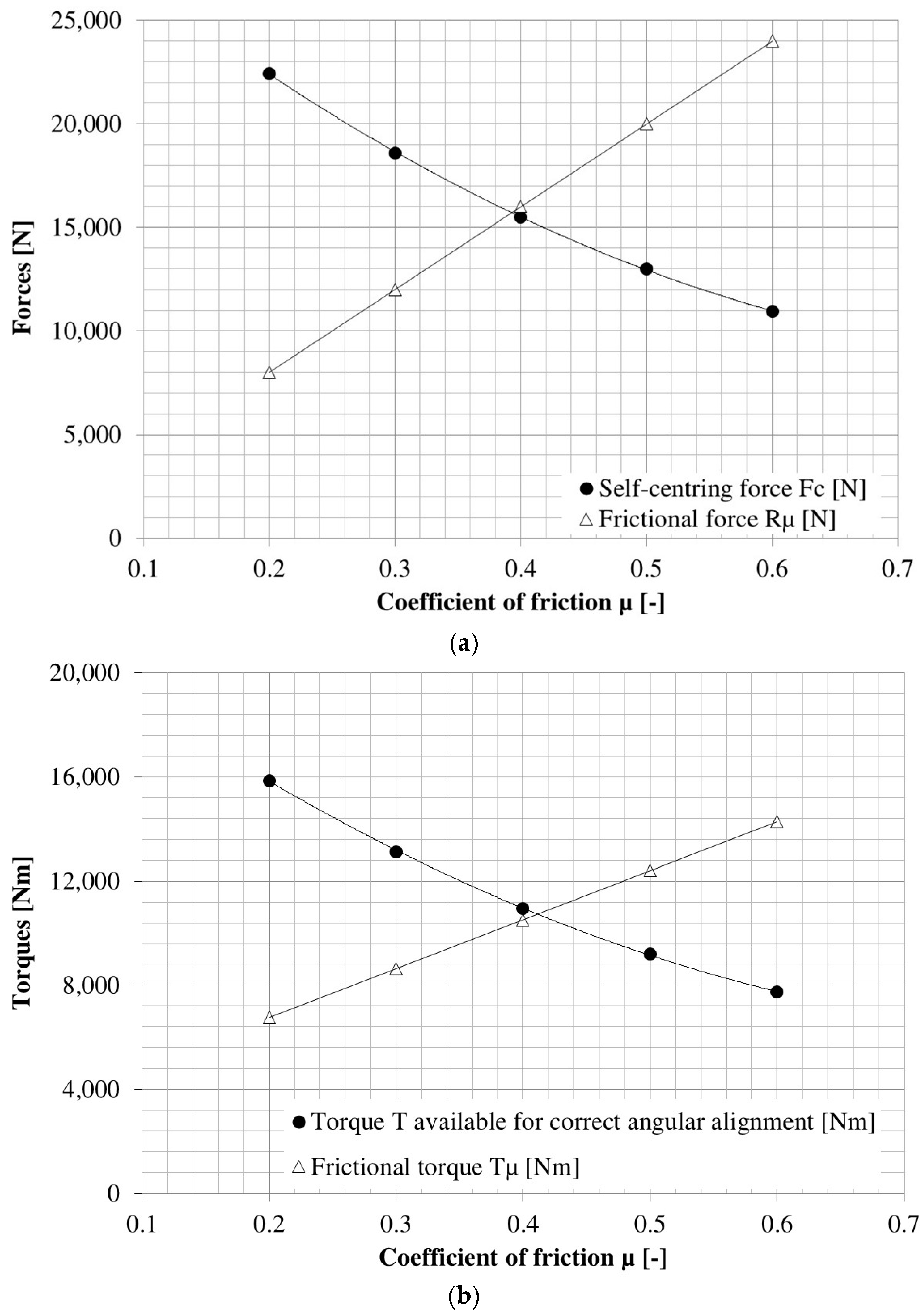
| Coefficient of Friciton μ | Angle of Friction ρ (°) | Axial Force Fa from Hydraulic Piston (N) | Tangential Force Fu (N) | Self-Centering Force Fc (N) | Torque Available for Correct Angular Alignment (Nm) | Frictional Force Rμ (N) | Frictional Torque Tμ (Nm) | Fc > Rμ | T > Tμ |
| 0.200 | 11.3 | 30,965 | 35,234 | 22,431 | 15,855 | 8000 | 6760 | YES | YES |
| 0.300 | 16.7 | 29,181 | 18,577 | 13,131 | 12,000 | 8640 | YES | YES | |
| 0.400 | 21.8 | 24,366 | 15,512 | 10,965 | 16,000 | 10,520 | NO | YES | |
| 0.500 | 26.6 | 20,445 | 13,016 | 9200 | 20,000 | 12,400 | NO | NO | |
| 0.600 | 31.0 | 17,190 | 10,944 | 7735 | 24,000 | 14,280 | NO | NO | |
© 2018 by the authors. Licensee MDPI, Basel, Switzerland. This article is an open access article distributed under the terms and conditions of the Creative Commons Attribution (CC BY) license (http://creativecommons.org/licenses/by/4.0/).
Share and Cite
Croccolo, D.; De Agostinis, M.; Fini, S.; Olmi, G.; Robusto, F.; Vincenzi, N. On Hirth Ring Couplings: Design Principles Including the Effect of Friction. Actuators 2018, 7, 79. https://doi.org/10.3390/act7040079
Croccolo D, De Agostinis M, Fini S, Olmi G, Robusto F, Vincenzi N. On Hirth Ring Couplings: Design Principles Including the Effect of Friction. Actuators. 2018; 7(4):79. https://doi.org/10.3390/act7040079
Chicago/Turabian StyleCroccolo, Dario, Massimiliano De Agostinis, Stefano Fini, Giorgio Olmi, Francesco Robusto, and Nicolò Vincenzi. 2018. "On Hirth Ring Couplings: Design Principles Including the Effect of Friction" Actuators 7, no. 4: 79. https://doi.org/10.3390/act7040079
APA StyleCroccolo, D., De Agostinis, M., Fini, S., Olmi, G., Robusto, F., & Vincenzi, N. (2018). On Hirth Ring Couplings: Design Principles Including the Effect of Friction. Actuators, 7(4), 79. https://doi.org/10.3390/act7040079


