Abstract
An optimized driving comfort with a low interior noise level is an important intention in the passenger car development process. The interior noise level caused by the dynamic interaction between the rolling tyre and the rough road surface and transmitted via the car-body is a significant component of the entire noise level. To reduce the road induced interior noise, in general, the chassis system has to be optimized. Passive measures often induces a trade-off between vehicle dynamics and driving comfort. To overcome this disadvantage in this paper, the development and realization of an active measure is proposed. For the purpose of active mechanical decoupling, an active control system is developed, the feasibility of the integration is investigated and its noise reduction potential is identified by vehicle tests. In a first step, a classical multi-channel and experimental-based structure-borne transfer path analysis of the full vehicle is realized to determine the dominant transfer paths. The concept for the active mount system (active mounts, multi-channel control system, sensors) is developed and parametrized by system level simulation. Mechanical components and power electronics of the active system are designed, manufactured and tested in the laboratory. Subsequently, the entire active system is integrated into the vehicle. The broadband adaptive feedforward algorithm is extended by certain measures in order to improve robustness and performance. Full vehicle tests are used to quantify the required specifications and the achieved effectiveness of the active vibration control system.
1. Introduction
The vehicle interior noise characteristic is one of the main important passenger comfort criteria and is therefore a focal point within a passenger car development process. The interior noise characteristic results from a composition of different noise phenomena (e.g., engine noise, rolling noise and wind noise). The rolling noise contribution is one of the most influential acoustic phenomena under urban driving conditions, especially on rough road surfaces. Due to the dynamic interaction between the tyre and the road, vibrations are induced into the chassis construction. This structure-borne noise is transmitted through the car-body structure to the ambient panels and causes vibrations leading to a sound radiation into the vehicle interior. The contribution of the structure-borne noise to the entire noise level is dominant in the frequency range up to , while the contribution of the direct airborne transmission of tyre noise can be neglected within this frequency range. Regarding an active system to improve acoustical comfort, different approaches were proposed depending on the particular application. Implementing an active noise control (ANC) system that makes use of available loudspeakers and additional microphones in the interior [1], a reduced sound pressure level of both narrowband disturbances, like engine orders, and stochastic broadband disturbances, i.e., road noise, could be achieved [2,3,4]. Within the field of research of smart structures, some investigations focus on the development of structurally integrated actuators, which should reduce structure-borne vibrations as well as the sound pressure level in the vehicle interior by active vibration control (AVC) and active structural acoustic control (ASAC) approaches [5]. One promising application transferred into application and practice are active engine mounts [6,7,8], which deal with the reduction of periodic noise and vibration. A further approach is the development of a stiff active mount for the purpose of mechanical decoupling [9]. This active mount is designed to also sustain high operational forces.
In order to prevent the passenger compartment from unwanted noise phenomena by tyre–road interaction, the coupling points from the chassis suspension to the car-body have to be decoupled. Therefore, an amount of mainly passive measures (e.g., rubber mounts) were investigated. However, regarding vehicle dynamics, a rather stiff connection between chassis suspension and car-body is preferred.
To overcome this conflict of objectives in this paper, an active mount chassis system is proposed, whereas the integration of a vibro-acoustic active system into the chassis construction to compensate broadband rolling noise is a rather novel research approach. The proposed design concept combines several disciplines for a holistic and efficient system design approach. The applied methods (transfer path analysis, coupled system simulation, adaptive multi-channel feedforward control, estimation of the required system performance and actuator design, operational tests and validation) were enhanced or adapted in order to suit the design process.
The following main goals are traced to implement an active mount chassis system:
- reduction of vehicle interior noise and optimization of vibrational acoustical comfort by minimization of the dynamic loads under varying operational conditions,
- benchmark of vibro-acoustic isolation systems and expansion of current technical applications,
- high static mount stiffness and the ability to apply dynamic forces with structure integrated piezoelectric actuators,
- solving the conflict between vehicle dynamics and acoustical comfort.
Within the scope of the work presented, the approach of designing and integrating an active vibration control system is based on a step-by-step procedure that is highlighted in the following sections of the paper. In a first step, relevant vibro-acoustic transfer paths are analyzed by means of an experimental-based transfer path analysis taking into account the preliminarily defined acoustic requirements (Section 2). The identification of relevant vibro-acoustic transfer paths allows for the derivation of a reduced numerical simulation model (Section 3). Here, models of different origins (i.e., structural dynamics, piezoelectric actuators, acoustics, and adaptive digital control) are combined in a coupled multi-physical simulation, which allows for the iterative optimization of both the piezo electric actuators as well as the adaptive control algorithm. The adaptive feedforward control algorithm (Section 4) is extended in order to increase the stability during actual driving tests with special regard to impulsive excitation, a secondary path dependent adaptation step size and distributed calculation on a multi-processor system. Based upon the requirements determined in the numerical simulation, an active subframe mount and a tailored power amplifier are developed and presented in Section 5. Finally, the performance of the active control system is investigated during vehicle rolling test rig evaluations.
The suggested design procedure is also applicable to a variety of other advanced problems in active noise and vibration engineering.
2. Vibro-Acoustical Vehicle Analysis
The vibro-acoustical flow of energy and relevant transfer paths from the source to the target can be identified realizing an experimental-based transfer path analysis (TPA) [10]. The knowledge of the structure-borne transfer paths is crucial for an effective integration of active isolation components in relevant paths. Based on an acoustic source, the noise is transmitted through the entire vehicle structure on structure-borne and airborne noise paths to the vehicle interior. The results of a TPA enables a qualitative and quantitative assessment of the contribution of each noise transfer path to the overall noise characteristic. Besides the vibro-acoustical transfer functions, the acting external loads can also be determined and be used for the dimensioning of the active mounts at the interface. In Figure 1, the classical TPA model is visualized. Under driving conditions on rough road surfaces, dynamic chassis forces are induced into the subframe. The structure-borne noise is transferred over the transfer paths between subframe and car-body. The direct measurement of the interface forces is complex because of the available space for the measurement systems between subframe and body. In addition, the direct integration of force sensors into the transmission path with the resulting modifications has a strong influence regarding the dynamic system behaviour. Therefore, the interface forces under operational conditions have to be determined indirectly, whereas different methods are described below. In decoupled transfer paths with adequate elasticity (e.g., between the active engine-sited and the passive body-sited connection points), the complex dynamic mount stiffness method (Equation (1)) can be used:
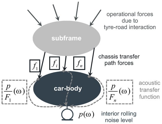
Figure 1.
Structure-borne noise transfer path model.
To apply the method, the knowledge of the complex dynamic mount stiffness and the relative displacements and are required to calculate the transmitted forces for the path i. Hereby, the mount stiffness commonly depends on the static load conditions, on the ambient temperature and on the excitation amplitude. Usually, the excitation frequency also has a strong influence on the mount stiffness characteristic. Within the chassis construction, rather stiff connections between adjacent components are realized to achieve an adapted handling performance and a direct force transmission. The high stiffness value leads to the effect that, under operational conditions, no significant relative displacements can be measured compared to random noise. This effect increases the error in measurement significantly under the boundary conditions described above. In that case, the matrix inversion method (Equation (2)) can be applied to identify the interface forces .
Besides the measurement of the vibro-acoustical transfer functions between the force input points and the comfort points in the vehicle interior, structural transfer functions between all points of force transmission also have to be measured to determine the structural interdependencies between the relevant connection points. The measured structural transfer functions of the body structure are combined within an inertance matrix . The inverted intertance matrix is multiplied with the measured acceleration of all body-sited connection points under operational conditions, which leads to an assessment of the operational interface force in each transfer path.
Under the consideration of the mathematical complex relations between all paths, the multiplication of the calculated operational transfer path forces with the measured vibro-acoustical transfer functions enables a synthesis of all partial contributions of the transfer paths to an overall noise spectra at a defined comfort point:
The contribution analysis of all transfer paths allows the direct comparison of the magnitude of all relevant noise transfer paths. The comparison between the synthesis result and the measured signal of the comfort relevant interior point enables the information of the synthesis quality of the noise transfer paths. One important advantage of the classical TPA approach is the separate discussion of the acting excitation characteristic of the active system and the vibro-acoustical transfer characteristic of the structure itself. This procedure therefore allows an assessment of the effectiveness of an active system integration into a certain transfer path. One disadvantage of the classical approach is the extensive measurement effort due to a large amount of sensor information and the required measured inertance transfer function matrix of the structure. The described TPA is evaluated for a middle-sized class vehicle with a four-cylinder diesel engine (21,105 kW). To interpret the interior rolling noise characteristic, the full vehicle is analyzed on a road surface with a special texture to excite the rolling tyre structure with a nearly white noise characteristic. To quantify the interior noise characteristic, a summarized spectra of the measured sound pressure level is evaluated on the driver ear position for a roll-out driving maneuver. The interior rolling noise can be measured on a proving ground or on a special rolling test rig with the identical excitation characteristic. The measurement on the rolling test rig offers the advantage to separate the influence of the axle contribution to the overall noise level, shown in Figure 2. The black line characterizes the interior sound pressure characteristic under rolling excitation of both the front and rear axle. The grey line describes the contribution of the front axle, whereas the grey dotted line offers the contribution of the rear axle to the overall interior noise level. Between the frequency range of and a dominant influence of the front axle on the sound level can be detected. Especially in a frequency range around a substantial maximum of the rolling noise characteristic can be identified and therefore motivates acoustical measures.
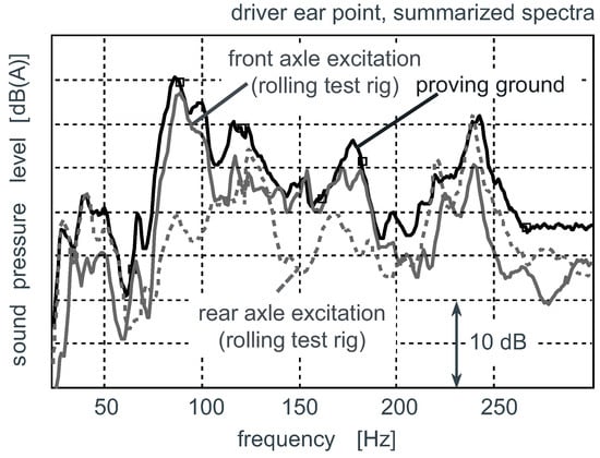
Figure 2.
Summarized vehicle interior rolling noise spectra and axle analysis [11].
Furthermore, a detailed comparison of the signal characteristics between interior noise and acceleration characteristics of the structure measured close to body-sited subframe connection points offer a high correlation. The TPA also yields a causal relationship. In Figure 3 (Left), the complex sum of the synthesized transfer path contributions is plotted versus the measured interior noise characteristic. Especially in the relevant frequency range of the synthesis describes the actual interior noise to the full extent. The accordance between the measured and the calculated characteristic can be interpreted in the way of an effective consideration of all relevant transfer paths. Differences between the characteristics are caused by missing transfer paths (e.g., airborne noise paths) and their phase influence on the complex sum. Therefore, the accordance can be used as a validation argument of the entire TPA model applied on the technical system.
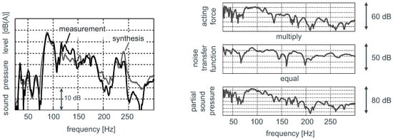
Figure 3.
Comparison between measured and synthesized vehicle interior noise (left) and structure-borne noise transfer at an exemplary body-sited subframe connection (right) due to front axle rolling excitation [11].
To evaluate the potential of an active subframe mount to reduce the interior noise, single transfer paths and their partial sound contribution are analyzed in detail. The partial sound contribution is divided into the calculated force acting under operational conditions and into the measured vibro-acoustical transfer function characteristic. Noticeable acoustical enhancements can be allocated to a high excitation respectively to a pronounced transfer behavior. In Figure 3 (right), a complete transfer path characteristic is exemplarily visualized for one subframe connection point in the vertical transfer direction.
The visualized characteristic shows an increased force level and a slight enhancement of the vibro-acoustical transfer behaviour which leads to an enhancement of the partial sound pressure characteristics about . The aim of an active system is to decrease the operational dynamic loads in this frequency range. The sound-correlated forces calculated by the matrix inversion method can therefore be used for the design process of the active chassis components. A detailed overview of all partial noise transfer paths results is given in Figure 4 and offers the complexity of the sound transfer due to rolling excitation. For all six connection points of the subframe to the car-body, the partial sound contribution is plotted for all three transversal directions. The calculation of the synthesized noise characteristic additionally includes the body-sited connection points of the suspension-strut dome. Due to the rigid connection of the subframe to the car-body and the spatial adjacency to each other, the force transmission points offer a significant vibro-acoustical interdependency. As shown in Figure 4, the vertical noise transfer contribution is dominant compared to the longitudinal and the lateral force direction, and therefore has to be reduced. Nevertheless, in the framework of the project, a one-directional active compensation can be realized. Hence, the force transmission in a vertical direction is influenced by the system.
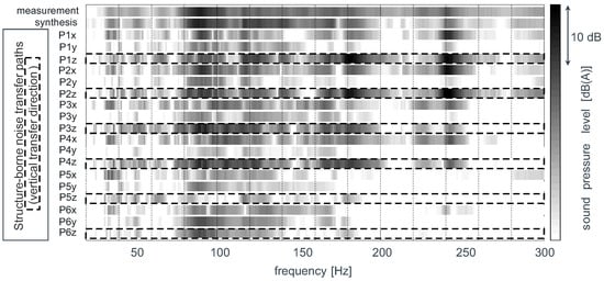
Figure 4.
Partial contribution characteristic of structure-borne noise transfer paths.
3. Numerical Simulation
The numerical simulation is carried out in order to evaluate the required operational dynamic forces of the active subframe. The control algorithm and several extensions that are described in the following section are also developed within the simulation environment. Furthermore, the preliminary numerical simulation enables a first estimation of the expected control performance. As a result of the TPA, the simulation model includes the dynamic system behavior in vertical direction, whereas an extension of the degrees of freedom may be considered in a prospective application. In order to set-up a holistic simulation model for the design of the active mount system sub-models of the structural dynamics, the electro-mechanical coupling, the acoustic-mechanical coupling and the control engineering shall be connected with each other by a suitable description of the mechanisms [12]. It should be noted that producing a sufficiently detailed illustration of all mentioned physical events within a model is necessary in this case. The description of the structural dynamics is carried out one by one for the subframe and the car-body. Therefore, connection elements between these two structures can be arbitrarily defined. The structure model is described by a state space representation:
The description of the state space model is made modally by measuring eigenmodes and damping. For the measurement, the subframe was dismounted and an experimental modal analysis is carried out. Transfer functions are measured between the connection points of the subframe and between the connection points of the car-body and the interior microphones at the test vehicle. Afterwards, an experimental modal analysis is carried out on test points of the subframe connection and finally the modal model of the car-body is generated. The models of the subframe and the car-body are coupled by six connection points. The simulation model, consisting out of six sub-models and an excitation, is pictured in Figure 5. The six links between car-body and subframe can be chosen separately either to be stiff, an elastomer material or to model an active mount. Therefore, the connections are able to describe different conditions that influence the interior noise due to an increased or reduced force . Different analyses of the mount qualities could be carried out and the effectiveness of the measures could be examined additionally. For the integration of an active mount, a model of the piezoelectric actuator is needed, which represents both mechanical and electrical properties. At first, a linear system behavior is presupposed. The model is represented in [13] and makes use of the electromechanical analogy as an equivalent circuit. The piezoelectric actuator is described by a simple two gate equivalent circuit. Here, the mechanical stiffness of the actuator is represented by , the viscous damping by , the electromechanical coupling by and the electrical capacity by . This network can be represented by different two gate matrices [14], whereas the impedance matrix should be focused at this point:
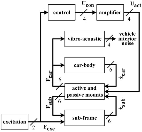
Figure 5.
Simulation model of the vehicle with the active mounts and vibro-acoustic model.
For the calculation of the vibro-acoustic behavior, a model has been identified from measured time data. This data arises from the transfer paths of the subframe connection points to the car-body into the vehicle’s interior. Finite impulse response (FIR) filters are used for the realization of the vibro-acoustical transfer functions. FIR filters are unconditionally stable because of their transversal structure, but, on the other hand, might require a high number of filter coefficients, particularly when modelling weakly damped systems because of their long impulse response. As shown in Figure 5, feedback of the acoustics to the structure vibrations is neglected. The excitation in the model is realized by means of two forces at the connection places of the transverse link. The spectral weighting of the excitation signals corresponds to the excitation spectra identified from the measuring. The transfer paths from the excitation of the engine and the exhaust systems to the vehicle’s interior are neglected since only the rolling noise is considered.
The simulation model is also used to evaluate the performance of the adaptive feedforward control algorithm. As indicated in Figure 5, the excitation forces are fed forward through the adaptive controller, generating four actuator control signals. Being not pictured, the algorithm pursues to minimize the force at the car-body site . Different investigations have been carried out in order to compare the performance of a multiple single-input-single-output (multiple SISO) topology, whereas each active mount only pursues to minimize the force at its own position, and a multiple-input-multiple-output (MIMO) topology, in which all active mounts try to minimize the force at all positions collaboratively. Due to the high stiffness of the chassis construction and the associated strong coupling between the active mount positions, the MIMO topology extended by an additional weighting matrix (Section 4.2) showed better results, compared to a multiple SISO topology.
The simulation results are summarized in Figure 6 for the case of an uncontrolled and a controlled scenario. Comparing the results to the measurement shown in Figure 2, a satisfactory agreement between the numerical investigation and the experimental results could be obtained.
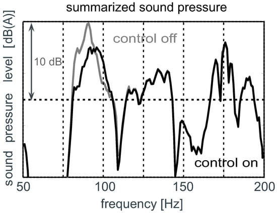
Figure 6.
Comparison of simulated sound pressure level by switching the active system on/off (active vibration control).
4. Adaptive Multi-Channel Feedforward Control
As mentioned in the beginning, interior noise is a superposition of different noise phenomena (e.g., engine noise, rolling noise and wind noise). Implementing an active vibration control system with additional actuators that serve as secondary source for the cancellation of disturbances, the vibration level at the mounting points of the subframe and thus the noise level in the passenger compartment should be lowered.
A feedforward system for the purpose of active vibration or noise control is quite often implemented on the basis of adaptive digital filters and requires a reference signal to drive the actuator in any case. Figure 7 shows an implementation of the multiple-input-multiple-output (MIMO) filtered reference least mean squares (FxLMS) algorithm with one reference signal. A suitable reference signal is correlated to the disturbance over the primary path . The reference signal is fed forward through an adaptive control filter and the secondary path with K actuators, generating the cancellation signal . The remaining error signal of dimension M is the superposition of the disturbance signal and the cancellation signals .
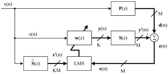
Figure 7.
Implementation of the MIMO FxLMS algorithm using one reference signal [15].
The LMS algorithm pursues the objective of minimizing the expectation value of the mean squared errors . Due to the quadratic characteristics of the error surface, there is only one least-squares minimum and, provided that the adaptation step size is set properly, the solution will converge to this global minimum. Using the LMS algorithm, this minimization is realized iteratively in every scanning cycle by means of a computed gradient estimate that points in the direction of the minimum of the error surface and an adaptation of the adaptive control filters along this gradient. The speed of convergence can be adjusted by means of an adaptation step size. The realized control system has error sensors, actuators and reference signals. For this purpose, a MIMO control system with multiple reference signals has to be set up.
A high correlation between the disturbance, in brief the acceleration at the four mounting points of the subframe in vertical direction, and a suitable reference signal, in brief the acceleration of the subframe in both transversal and vertical direction, were identified by means of the TPA in a previous step.
However, the complexity, the computational burden and the number of adjustable parameters increase drastically for a multi-channel control system and therefore the adjustment of the adaptation parameters is difficult to realize [2,15]. For a multi-channel control system with several reference signals and MIMO topology, independent contributions to the adaptation process of the control filters basically arise. Different adaptation step sizes have to be selected with respect to the spectral distribution of the reference and error signals as well as the characteristics of the secondary paths.
The following sections present the expansion of the single reference control algorithm to a multi-reference topology, applying both a normalized adaptation step size as well as a leakage factor to avoid long-time divergence (Section 4.1). Furthermore, the proposed algorithm uses an optimized adaptation step size, taking the secondary path transfer path characteristics (Section 4.2) into account. Figure 8 shows the applied multi-reference control algorithm that was also extended by an impulsive noise protection (Section 4.3), residual noise shaping filters (Section 4.4) and a feedback neutralization (Section 4.5). The distribution of the control algorithm for a multi-processor implementation is presented in Section 4.6.
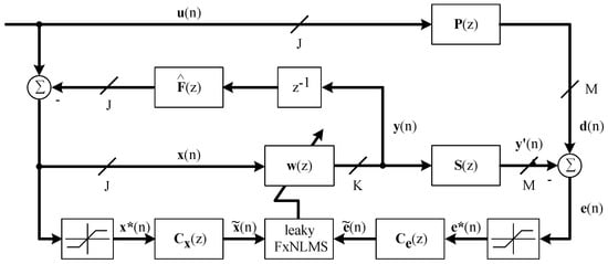
Figure 8.
Proposed modified multi-reference MIMO normalized FxLMS algorithm implementing an impulsive noise protection, residual noise shaping and feedback neutralization.
4.1. Extension to Multi-Reference Topology, Normalization and Leakage Factor
Expanding the control algorithm for a multi-reference application requires J data sequences of the reference signals of length . These are implemented as column vectors just as the adaptive filter weights :
The k-th actuator signal is then computed by feeding the reference signals through the corresponding control filter and summing up all components for each reference signal due to superposition:
Starting with the update equation for a single reference signal MIMO FxLMS algorithm [15] with M error sensors and K actuators, the update equation of the adaptive control filters can easily be extended for J reference signals in case of a multi-reference feedforward control scenario, introducing an additional index j
The adaptation equation uses the modified reference and error signals respectively. The filtered reference signal vector is gained form linear convolution and a secondary path estimate [15], which can be obtained by means of system identification using adaptive finite impulse response filters [16]. According to Equation (6), is the data sequence of the modified reference signal:
The adaptation step size is inversely proportional to the filter order and the power of the filtered reference signal and can thus be normalized with respect to both factors, leading to the normalized filtered reference LMS algorithm (FxNLMS), whereas the adaptation step size adjusted by the user is now given by a global normalized adaptation step size . The update equation is also extended by a leakage factor in order to avoid long-term divergence [17]:
The power of the filtered reference signal can be computed by means of a discrete low pass filter [15] and is limited in case of a low signal power, which would lead to large adaptation step sizes and thus instability in case of low excitation or if the secondary path has small influence.
4.2. Optimized Adaptation Step Size for MIMO FxLMS Control Systems
An essential improvement in the adaptation behavior is reached through a secondary path dependent weighting matrix. A recommendation to neglect a weakly coupled secondary path transfer function by means an additional weighting factor that modifies the adaptation step size is described in [15]. This approach was successfully tested at a truss structure for a multi-order narrowband MIMO control system, whereas weakly coupled transfer paths of the secondary path transfer matrix were neglected in order to reduce the computational burden [18]. The proposed modification of the adaptation step size does not intend to neglect some secondary paths, but rather to reduce the adaptation step size for weakly coupled secondary paths. Regarding Equation (12), the adaptation step size is multiplied by a scalar weighting factor resulting in a modified adaptation step size :
For the purpose of simplification, the same weighting matrices are being used for all reference signals and the weighting factor is held constant over time and can thus be calculated offline:
The weighting factor is calculated by means of the frequency response of the secondary path transfer matrix, which is evaluated in a relevant frequency range. The frequency response of a the finite impulse response filter can be calculated according to Equation (15):
A rating factor of every transfer function is calculated by means of Equation (16) with respect to the relevant frequency range , whereas represents an additional weighting factor:
The rating factor was evaluated within the relevant frequency range from 80 to . The weighting factor is computed by normalizing the rating factor with respect to the best actuator for each sensor position (Equation (17)). Setting , the rating factor computes the mean signal power for white noise excitation, which results in the best control performance within driving tests:
To summarize, the update equation for the adaptive filter weights results in Equation (18), applying the modified adaptation step size :
4.3. Impulsive Noise Protection
The attainable control performance applying the FxLMS algorithm might decrease for impulsive disturbances. Although the presented work [19,20] is dealing with highly impulsive signal characteristics, the modification of the algorithm for the adaptation of the control filter weights introduced by [20] is also able to improve the robustness of the control algorithm in this application. Here, instabilities appeared primarily at transient impulsive excitations, like transverse grooves in the road surface. As shown in Figure 8, the impulsive noise protection is being used for both the error signals and the reference signals. As introduced by [20], the modified reference signal and the modified error signal are gained from clipping the signal by means of a lower bound and an upper bound .
The parametrization depends on the signal statistics of the error and reference signals, respectively. For the calculation of the lower and upper bound, measurement data of a test drive was used. An exemplary recorded time series is illustrated in Figure 9, whereas impulsive excitation mainly occurs in the end of the measurement after a time of approx. 45 s, which caused some instability issues. Figure 9 also shows the cumulative distribution function that can be computed from the probability density function of the relevant time series as well as the selected lower and upper bound.
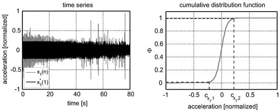
Figure 9.
Exemplary time series and modified signal (left); cumulative distribution function of the time series and selected lower and upper bound in percentile (right).
The lower and upper bound are experimentally selected as percentile of and , respectively. The modified signal is also illustrated in Figure 9. For the case of clipped reference and error signals, the adaptation is likely to behave like a signed-reference signed-error algorithm and thus improve robustness, but in a certain way reducing control performance. Furthermore, it should be mentioned that the evaluated time series depicts a marginal case with a strong excitation that wasn’t observed during normal driving conditions. Thus, the impulsive noise protection would only take effect in case of high amplitudes and only during 2% of the measurement duration due to the selected percentile of .
4.4. Residual Noise Shaping
As shown in Figure 2, the A-weighted sound pressure has a significant contribution in the frequency range at approx. . However, this peak-like characteristic did not appear in the error and reference signals. In order to direct the performance of the control system to the targeted frequency range, additional shaping filters for both reference signals and error signals are implemented (Figure 8). In this application, 4th order Bessel bandpass filters with a passband of 80 to are implemented as infinite impulse response (IIR) filters. The method of residual noise shaping was introduced by [21,22].
4.5. Feedback Neutralization
In many applications, especially when dealing with measured reference signals, feedback effects may occur. Driving the actuators may distort the measured reference signal via a feedback path . For this purpose, the control algorithm was extended by a feedback neutralization [15]. In case of a multi-reference control system with several actuators, an estimation of the feedback path transfer matrix could be identified using adaptive digital transversal filters [16]. The calculation of the neutralized reference signals requires a data sequence of the past actuator signals, whereas the data sequence is delayed by one scanning step:
The corrected reference signal is then computed by means of linear convolution (*) of the delayed data sequence and the feedback path estimate :
Considering an ideal case, the neutralized signal would equal the reference signal, which would have been measured when actuators remain deactivated.
4.6. Sharing Computational Burden for Multi-Processor Digital Signal Processing
Due to the high computational burden of a broadband multi-channel feedforward control system, a distributed implementation on a multiprocessor system and thus the distribution of computational burden is advisable. The feasibility for a decentralized vibration control concept using the FxLMS algorithm was previously investigated in [23] and successfully applied in a distributed application with two embedded signal processing nodes that are able to communicate with each other across a CAN network [24].
Within this project, the control algorithm was implemented on a multiprocessor rapid control prototyping system (dSPACE DS1006), allowing the distribution of the control algorithm on four independent processor cores. The distribution was realized regarding each sensor position and is illustrated in Figure 10.
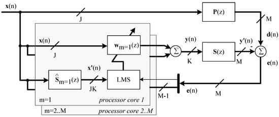
Figure 10.
Distribution of the control algorithm for a multiprocessor application.
The previously mentioned extensions of the control algorithm, in brief the modification of reference and error signals and the feedback neutralization as well as AD-conversion and DA-conversion are computed by the master processor core. Each of the four processor cores (one master, three slaves) computes the relevant filtered reference signals by means of a secondary path transfers sub-matrix. The control filters are adapted for a single error signal.
5. Active Subframe Mount
Installing a controlled active mount system, the acceleration at the mounting points of the subframe at the car-body structure due to the tyre–road interaction should be minimized. Besides a suitable signal processing unit, an active mount system consists of the mount itself and the respective power amplifier. Applying piezoelectric actuators into the active mount ensures both: carrying operational loads with a demanded high stiffness and the initiation of dynamic forces. Thus, piezoelectric actuators are well qualified for the decoupling of mechanical structures.
The following challenges have to be considered in the mount design process:
- realization of adequate operating displacements/forces for compensation,
- vehicle integration under consideration of the available designed space without a significant modification of the subframe and its connection,
- verification of an operational stability under driving conditions,
- realization of an integrated amplifier adapted to vehicle operational conditions and able to drive the active mount (actuator) in the desired frequency range.
To achieve the requirements, a cascade mount design with multiple actuators in a parallel and serial arrangement is realized. For each mount, six low voltage piezoelectric actuators are collocated in two levels. The cross-sectional area of one actuator is about 49 mm2, the height of a single actuator is about . Figure 11 (left) shows the package of the active subframe mount with a height of and a diameter of . This kind of mounting type achieves the mechanical requirements concerning stability, whereas mechanical displacements of about and a blocking force of can be realized in the desired frequency range up to .
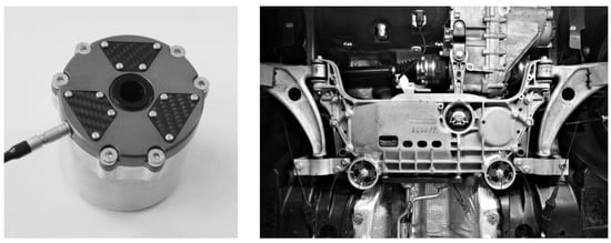
Figure 11.
Active subframe mount (left) and complete vehicle (right) [11,25,26].
To integrate the mounting package, a modification of the subframe construction is required. At all coupling positions, the mounting package sockets are welded to the subframe, and the mounting packages are pressed directly into the sockets and are fixed with screws. The modular active mount design allows an efficient analysis of the efficiency of different variants. In Figure 11 (right), the installation situation of the four active subframe mounts in the entire vehicle is visualized. The active mounts between the front axle subframe and the inner tunnel beam can be seen directly and both junctions between the subframe and the outer longitudinal beam are covered by the suspension arms.
However, there are important requirements concerning power electronics and power amplifiers when utilizing piezoelectric actuators. A high linearity over a wide frequency range and a low signal-to-noise ratio are the first that should be mentioned. Furthermore, driving high capacitive loads especially at high frequencies requires large dynamic currents. Within the scope of the project, self-developed power amplifiers were successfully tested during driving tests (Figure 12).
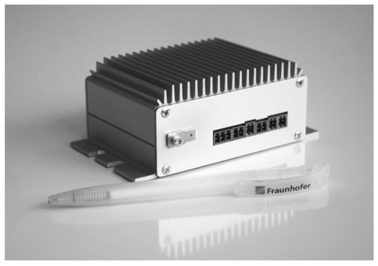
Figure 12.
Compact amplifier for piezoelectric actuators in AVC applications.
The installed low voltage piezoelectric actuator types are manufactured in mass-production, require a positive driving voltage between 0 and and should be driven up to . The amplifier is supplied via the on-board power supply. The maximum driving voltage of is provided by means of an internal power converter. The piezoelectric actuators are then controlled by integrated class-AB amplifiers. Each amplifier drives a capacitive load of with a maximum peak-to-peak voltage of up to a frequency of . The total harmonic distortion for a pure capacitive load of up to is less than for the driving voltage and less than for the driving current. An operation of the active mount system requires eight amplifiers in total. A detailed description of the developed amplifier, performance test and further applications will be introduced in an additional publication.
The power amplifiers and a dSPACE control system are integrated in the rear luggage space and enable the investigation of different control strategies. Besides the interior noise signals acquired by two microphones (ASAC), body-sited structural acceleration signals (AVC) are also used as error signals within the control strategy. The entire active system components are independent from the vehicle electronics and supplied by the vehicle battery.
To develop the active system technology, an Advanced Car Structure Test Facility (ASF) at the Fraunhofer LBF (Darmstadt Germany) is used and shown in Figure 13. The aim of the test facility is to excite the front axle to vibrations resulting in dynamical response characteristics of the car-body, which is equivalent to the operational conditions under rolling noise excitation. Two shakers are used to excite the chassis components on both axle sides in the vertical direction. To reproduce the operational conditions, a separate signal control strategy for the electrodynamic shakers is used. The signal characteristics of the dynamic vehicle response under operational conditions are used as a target signal, and the resulting dynamic vehicle response is therefore nearly equivalent.
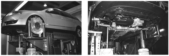
Figure 13.
Test rig analysis [11,25].
The control parameters were adapted within the ASF test rig, as well as in driving tests at a local airport in Darmstadt (Germany). Including the test rig measurements presented in the following section, the vehicle was driven about in total.
6. Active System Performance Analysis
To identify the vibro-acoustic performance of the active system, the entire vehicle is analyzed experimentally using a rolling test rig with a single excitation of the front axle. The interpretation of the vibro-acoustic vehicle characteristics is gained by analyzing the summarized signal spectra for a roll-out procedure over a large velocity range. In Figure 14, measured acceleration characteristics of two body-sited subframe connection points under the described operational conditions are visualized. The dotted line offers the vibration level with an inactive control system. If the multi-channel control system is switched to an active state, the active subframe mounts lead to a significant reduced interface force excitation level and therefore a reduced vibration level is observed. The target frequency range is adjusted to 80 to .
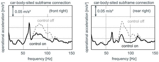
Figure 14.
Comparison of car-body-sited vertical accelerations at the subframe mount connections by switching the active system on/off (active vibration control).
The reduced excitation level into the car-body structure directly affects the interior rolling noise level, which is significantly reduced on driver’s and co-driver’s ear position (see Figure 15).
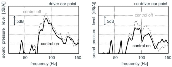
Figure 15.
Resulting vehicle interior noise spectra due to rolling excitation.
7. Conclusions
Within the presented work, active front axle subframe mounts are developed and integrated in a middle-sized passenger car to reduce the interior noise caused by road excitation. As a result of a numerical simulation, required dynamic forces of the active mounts are estimated. Four active subframe mounts based on piezoelectric actuators are designed, validated and integrated into the car-body. Due to the active system technology combined with a suitable control algorithm, the structural vibration level and the resulting vehicle interior noise are significantly reduced under operational conditions. The experiences with the active subframe mount performance gained within this project highlights a distinctive research demand in the area of active system technology. The active control system developed in this project represents one possible solution for the active control road noise at the front axle. Thus, regarding the high complexity of the noise, vibration, and harshness (NVH) behavior, special attention should be paid to the early stage NVH design also taking into account active control in order to find an optimal solution.
Author Contributions
G.G. and A.M. conducted the experiments, set up a comprehensive experimental characterization for the vehicle, analyzed and evaluated the data; S.H. and H.A. developed the simulation strategy; H.A. established the simulation model and performed the numerical simulation; J.M. developed the control approach, integrated the active system and investigated the control system during the final experiments. The authors wrote the sections regarding their respective research field mentioned above. All authors helped to revise and improve the overall paper. S.H. organized and structured the paper.
Funding
This work was supported by the research project FIEELAS (03X3026) funded by the German Federal Ministry of Education and Research (BMBF). The support is greatly acknowledged.
Acknowledgments
Special thanks go to Björn Seipel, Christoph Klein and Tobias Drögemüller, who were responsible for the design and the development of the active mount, the development and test of the piezoelectric power amplifier, the implementation of the subframe and realization of the tests in the ASF test rig.
Conflicts of Interest
The authors declare no conflict of interest.
Abbreviations
| AD | Alternating current to Direct current |
| AG | Stock corporation (translated from German) |
| ANC | Active Noise Control |
| ASAC | Active Structural Acoustic Control |
| ASF | Advanced Car Structure Test Facility |
| AVC | Active Vibration Control |
| CAN | Controller Area Network |
| DA | Direct current to Alternating current |
| e.g. | for example |
| FIEELAS | Functionally Integrated Electro-active Elastomer Mounting Systems (translated from German) |
| FIR | Finite Impulse Response |
| FxLMS | Filtered reference Least Mean Squares |
| LBF | Laboratory for Structural Durability (translated from German) |
| LMS | Least Mean Squares |
| MIMO | Mulitple-Input-Multiple-Output |
| SISO | Single-Input-Single-Output |
| TPA | Transfer Path Analysis |
References
- Elliott, S.J. A review of active noise and vibration control in road vehicles. In ISVR Technical Memorandum, 981; University of Southampton: Southampton, UK, 2008. [Google Scholar]
- Elliott, S.J. Signal Processing for Active Control; Academic Press: New York, NY, USA, 2000. [Google Scholar]
- Zafeiropoulos, N.; Zollner, J.; Kandade Rajan, V. Active Road Noise Cancellation for the Improvement of Sound Quality in the Vehicle. ATZ Worldw. 2018, 120. [Google Scholar] [CrossRef]
- Oh, C.; Ih, K.; Lee, J.; Kim, J.K. Development of a Mass-producible ANC System for Road Noise. ATZ Worldw. 2018, 120. [Google Scholar] [CrossRef]
- Mayer, D.; Millitzer, J.; Bein, T. Integrated Solutions for Noise and Vibration Control in Vehicles. SAE Int. J. Passeng. Cars Mech. Syst. 2014, 7, 1183–1193. [Google Scholar] [CrossRef]
- Gäbel, G.; Schulze, C.; Mohr, A.; Meschke, J.; Marienfeld, P.M.; Karkosch, H.-J.; Genderjahn, R.; Preussler, S. Active engine mounts—Results of a case study. In Proceedings of the third Aachen Acoust, Colloq, Aachen, Germany, 21–23 November 2011. [Google Scholar]
- Römling, S.; Vollmann, S.; Kolkhorst, T. Active Engine Mount System in the New Audi S8. MTZ Worldw. 2013, 74, 34–38. [Google Scholar] [CrossRef]
- Kraus, R.; Herold, S.; Millitzer, J.; Jungblut, T. Development of active engine mounts based on piezo actuators. ATZ Worldw. 2014, 116, 50–55. [Google Scholar] [CrossRef]
- Herold, S.; Mayer, D.; Hanselka, H. An adaptive interface for the neutralization of structural vibrations. In Proceedings of the 2000 European Congress on Computational Methods in Applied Sciences and Engineering, Barcelona, Spain, 11–14 September 2000. [Google Scholar]
- Mohr, A.; Gäbel, G.; Hagerodt, B.; Meschke, J. Analyse der Schallübertragung in Gesamtfahrzeugen. In Seminar “Mess- & Analysetechnik in der Fahrzeugakustik”; Deutsche Gesellschaft für Akustik: Berlin, Germany, 2011. [Google Scholar]
- Gäbel, G.; Meschke, J. Aktive Systeme zur Körperschallentkopplung im Automobil. In FAA-Workshop “Marktpotenzial und Anwendungen von aktiven Systemen”; Fraunhofer-Allianz Adaptronik: Darmstadt, Germany, 2011. [Google Scholar]
- Herold, S.; Atzrodt, H.; Mayer, D.; Thomaier, M. Integration of different approaches to simulate active structures for automotive applications. In Proceedings of the 2005 Forum Acusticum, Budapest, Hungary, 29 August–2 September 2005. [Google Scholar]
- Mayer, D.; Atzrodt, H.; Herold, S.; Thomaier, M. An approach for the model based monitoring of piezoelectric actuators. Comput. Struct. 2008, 86, 314–321. [Google Scholar] [CrossRef]
- Fettweis, A.; Hemetsberger, G. Grundlagen der Theorie Elektrischer Schaltungen (Fundamentals of Electric Circuit Theory); Brokmeyer: Bochum, Germany, 1995. [Google Scholar]
- Kuo, S. Morgan, D. Active Noise Control Systems; Wiley & Sons Inc.: New York, NY, USA, 1996. [Google Scholar]
- Widrow, B.; Stearns, S. Adaptive Signal Processing; Prentice-Hall Inc.: New Jersey, NJ, USA, 1985. [Google Scholar]
- Gitlin, R.; Meadors, H.; Weinstein, S. The Tap-Leakage Algorithm: An Algorithm for the Stable Operation of a Digitally Implemented, Fractionally Spaced Adaptive Equalizer. Bell Syst. Tech. J. 1982, 61, 1817–1839. [Google Scholar] [CrossRef]
- Kauba, M.; Millitzer, J.; Mayer, D.; Hanselka, H. Multi-Channel narrowband Filtered-x-Mean-Square algorithm with reduced calculation complexity. In Proceedings of the 2011 5th ECCOMAS Thematic Conference on Smart Structures and Materials, Saarbrücken, Germany, 6–8 July 2011. [Google Scholar]
- Sun, X.; Kuo, S.; Meng, G. Adaptive algorithm for active control of impulsive noise. J. Sound Vib. 2006, 291, 516–522. [Google Scholar] [CrossRef]
- Akhtar, M.; Mitsuhashi, W. Improving performance of FxLMS algorithm for active noise control of impulsive noise. J. Sound Vib. 2009, 327, 647–656. [Google Scholar] [CrossRef]
- Tsai, J. Active Noise Contol Systems: Secondary Source Arrangements, Frequency Shaping, and Electroacoustic Path Modeling. Ph.D. Thesis, Northern Ilinois University, DeKalb, IL, USA, 1993. [Google Scholar]
- Kuo, S.; Tsai, J. Residual noise shaping technique for active noise control systems. J. Acoust. Soc. Am. 1994, 95, 1665–1668. [Google Scholar] [CrossRef]
- Kauba, M.; Herold, S.; Mayer, D. Feasibility Investigations for a Decentralized Vibration Control Concept with embedded Control Nodes using the Filtered-X-Least-Mean-Squares-Algorithm. In Proceedings of the 2009 ECCOMAS Thematic Conference on Smart Structures and Materials (SMART’09), Krakow-Krynica Zdroj, Poland, 11–14 January 2009. [Google Scholar]
- Kauba, M.; Mayer, D. Netzwerkbasierte Umsetzung einer verteilten aktiven Schwingungskompensation. In Proceedings of the 36th Jahrestagung für Akustik (DAGA), Berlin, Germany, 15–18 March 2010. [Google Scholar]
- Atzrodt, H.; Herold, S.; Drögemüller, T.; Millitzer, J.; Seipel, B. Untersuchung zur aktiven Entkopplung von Fahrwerkskomponenten. In Proceedings of the 37th Jahrestagung für Akustik (DAGA), Düsseldorf, Germany, 21–24 March 2011. [Google Scholar]
- Atzrodt, H.; Drögemüller, T.; Klein, C.; Millitzer, J.; Seipel, B. Umsetzung und Erprobung von aktiven Lagern im Fahrwerksbereich. In Proceedings of the 38th Jahrestagung für Akustik (DAGA), Darmstadt, Germany, 19–22 March 2012. [Google Scholar]
© 2018 by the authors. Licensee MDPI, Basel, Switzerland. This article is an open access article distributed under the terms and conditions of the Creative Commons Attribution (CC BY) license (http://creativecommons.org/licenses/by/4.0/).