Abstract
This paper presents all the significant nonlinearities that exist in the description of an electro hydraulic actuator for flexible nozzle thrust vector control. Starting from practical possibilities of the theory of a nonlinear system (which are based on the analyses of one nonlinearity or one equivalent nonlinearity in the proximity of the linear description of an actuator), this paper explores the possibilities of additional analyses of a nonlinear electro hydraulic actuator for flexible nozzle thrust vector control. These explored possibilities can provide information that is useful for the design of the control algorithm, as well as for the general design of a flexible nozzle and actuator system.
1. Introduction
Flexible nozzle thrust vector control has many characteristics that justify its application in practice. From a technological perspective, it is a relatively simple construction consisting of a flexible nozzle. However, relatively large forces are demanded from the actuator. The deflection of the nozzle deflects the engine thrust vector and generates a momentum about the rocket center of gravity. The flexible nozzle design application is typical for rocket ballistic engines, and provides a clear advantage compared to electro hydraulic actuator systems in the past. However, today, electro mechanical actuators of 40 to 50 kW are taken into consideration as their alternatives. The work presented in this paper cannot be compared to any existing work, because in this paper, we use the idea of a flexible nozzle which can be introduced through a model of flexible joint with shearing between the two rubber bricks with reinforcement.
A technologically improved electric current feedback loop (that became the source of the main internal feedback compared to the feedback per force) has given electro mechanical actuators performances that approximate those of electro hydraulic actuators. Along with the inherited advantage of simple maintenance, they further increase the competitiveness of electro mechanical actuators towards electro hydraulic actuators. They have a shearing load type for which we can consider Hook’s law to be applicable. Based on this, in the modeling phase, this load can be represented as an ideal spring within a linear approach to modeling. It is extremely important to understand how the structured nonlinear nature of an electro hydraulic actuator is manifested. Most importantly, it is necessary to raise the question of how the nonlinear flow characteristic of a piston distributor is correlated with the flexible load characteristic. Flexible nozzle control is a positional problem of control that needs to be discussed considering the very important fact that it is impossible to measure a nozzle’s reference position, but only the position of the hydraulic cylinders’ piston. Within certain discussions, one can consider the fact that the description of flexible nozzle control is considered to be a positional problem, and perhaps a more adequate description would be to have the actuator systems controlled per force [1].
The main problem is to define the reference force, which brings up an important question of comparison between the actuator system’s bandwidth per force and per position. The previous position hides the reason of giving advantage to flexible nozzle control through electro hydraulic actuator, because electro mechanical actuators do not have bandwidth per force in a closed circuit, which is eminent for an electro hydraulic actuator system in an open circuit. Figure 1 depicts a flexible nozzle consisting of four main subsystems: the movable nozzle section, the attachment to the rocket motor, the actuation system, and the flexible joint. The flexible joint (bearing) is a non-rigid pressure-tight connection between the rocket motor and a movable nozzle that allows the nozzle to be deflected in a specified direction. Certain studies justify the use of an internal feedback loop per force and external per position [1,2,3,4]. This approach to hydraulic actuator dynamic analysis (shown in Figure 2) is greatly simplified in the interest of developing an easy-to-understand introduction into the integration nature of the hydraulic cylinder.
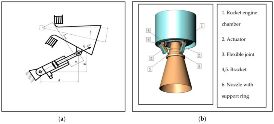
Figure 1.
(a) Flexible nozzle and actuator—scheme. (b) Flexible nozzle—model.

Figure 2.
Actuator in the rocket control structure. where: K—gain, Kα—feedback gain, —transfer function of rocket, β—control position, Δ—dead band value.
2. Actuator System—Description in the Model of a Rocket
In many models of a rocket, in the early stages of the rocket design, the actuator system is represented by the non-linearity of insensitivity zones with saturation types. Aside from true physical insensitivity, this non-linearity has an additional part from hysteresis-type non-linearity. It generally describes static characteristics of a loaded actuator in the combination control signal-position, control signal-force and stroke-force (i.e., as an element without inertia). By developing this model further, as depicted in Figure 2, a significantly enhanced model which considers the character of a loaded actuator and the integrated nature of the position system is being created. Within the structured description of the electro hydraulic actuator, special attention should be paid to having all feedback loops—based on true contributors to the system—presented, as well as those feedback loops which are created by mutual internal influences that do not need any special contributors to the actuator system. By the adequate measurement of forces, stroke, and control signal, hysteresis-type non-linearities are obtained, which contribute to the estimation accuracy of the actuator’s operations dependency on all influences. This is done without only relying on the simulations’ feedback from linear and nonlinear mathematical models, with a control algorithm in a closed control loop [5,6].
3. Nonlinearity in Electro Hydraulic Actuator System
The non-linear nature of an actuator system is observed in two ways. The first is to have the entire non-linear model defined, and the second is to linearize the square root type nonlinearity which characterizes the flow characteristic of the spool/sleeve distributor and thus generates the linear part of the system in its description, while defining and elaborating static nonlinearities in the actuator system related to saturation per pressure and flow. Figure 3 depicts the structure of an actuator with saturation per flow and pressure, which are indirectly presented via velocity and acceleration. Based on the description in Figure 2, a very useful diagram can be constructed (as shown in Figure 3 and Figure 4) [7] that shows the frequency and amplitudes, by which manifestations of the non-linear nature of actuator systems from saturation per pressure and flow can be avoided. The realization of this dependency enables the design of a special expert filter for a control signal that prevents the occurrence of unwanted combinations of amplitudes and frequencies. Especially important is the fact that the most relevant nonlinearity is the one of hysteresis type in the elaborated actuator system. Even though there are different types of hysteresis, this particular case includes hysteresis from the distributor, experimental results as shown in Figure 5 and Figure 6, and model description as shown in Figure 7, combined with the hysteresis of elastic load. Basically, every actuator system has its general description through a hysteresis function that transfers to an insensitivity zone non-linearity type (as shown in Figure 8), which is obtained by experimental record of static characteristics. Something similar occurs in distributors as a functional substructure—the hysteresis of the electro mechanical converter (hysteresis that is generated by the electromagnetic nature of the converter), together with the hysteresis of the entire structure for work fluid distribution, which is generated from clearance and friction that is partially compensated by the DITHER signal. Figure 5 shows the experimentally recorded nature of a distributor’s hysteresis (control signal–distributor spool movement), while Figure 6 shows diagram control signal–pressure difference that also represents manifestation of hysteresis—a phenomenon of amplification per pressure (i.e., force).

Figure 3.
Basic simulating non-linear model of an actuator with non-linearities of saturation type.
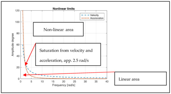
Figure 4.
Diagram that shows frequency and amplitude dependency and manifestation of system’s non-linear nature and saturation from velocity and acceleration.
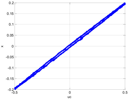
Figure 5.
Distributor hysteresis, test +/− 50% control signal–spool movement.
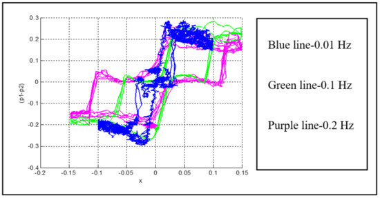
Figure 6.
Spool movement–pressure difference, lines A and B blocked, test system.
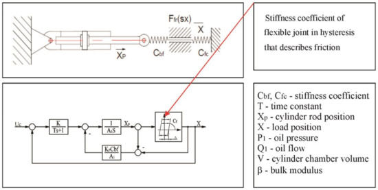
Figure 7.
Model of an actuator with small inertial load, friction, and elastic load.
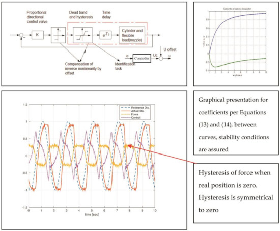
Figure 8.
Behavior of flexible joint with control offset (0.080 V, K = 1), control per position, elastic and inertial loads.
As previously mentioned, it is difficult to have a mathematical description of dominant hysteresis type non-linearity in a flexible nozzle actuator system (Figure 9). This is why the discussion on the following approach is proposed: to have a flexible nozzle treated as a load with dominant internal friction and as a small inertial load in combination with the ideal elastic (position) part of a load. In this case, mathematical description leads to a universal function of hysteresis for flexible load that—besides considerations in control synthesis—could be used to determine the rigidity of a flexible joint when it affects the stability of an actuator system in a positive or negative way. This is of extreme importance in constructing the joint between the flexible nozzle and the rocket motor chamber. Justification for this approach are the flexible nozzle modeling techniques which use the functions of internal frictions as a consequence of shearing in a flexible joint that is represented by the dynamic behavior of rubber [8].
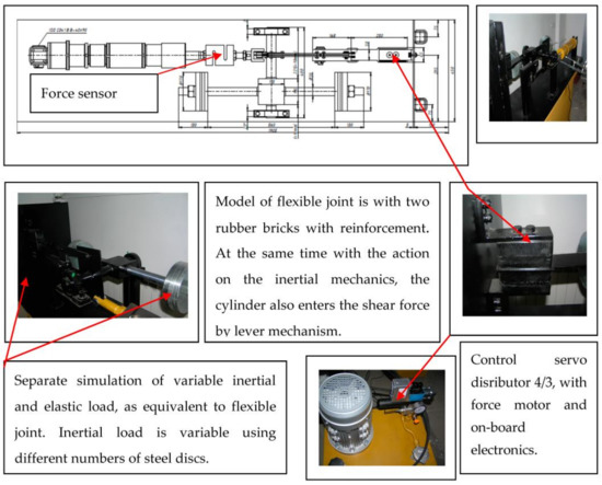
Figure 9.
Test system for qualitative and functional simulation of flexible joint nozzle.
It is completely reasonable to neglect inertial load compared to flexible, in order to have the actuator load presented through an elastic joint with a nozzle, load presented via a non-linear function of friction (in a flexible joint there is shearing, meaning that there is internal friction between composite layers of rubber), and eventually lining with an ideal spring. In this way, by very simple mathematical description, the equation is derived that describes the function of clearance, which can be considered a function of hysteresis, which is much easier to describe than the “elastic hysteresis” described by a differential Equation (1), Bouc–Wen model [2], and for parameters determination for which a very complex experiment is required. By non-linearity—as described in Figure 7 and parameter Cf—the stiffness of a flexible joint is depicted in a much easier and simpler way than by Equation (1). An alternative to description of a flexible joint is basically mathematical description through LOOK UP function (in MatLab), based on experimental data, as shown in [1].
Basic equations of linear actuators (cylinder) without initial load are presented as:
If we put Equation (2) under the integral:
Ideal actuator’s flow:
Based on Equations (2), (4) and (5) and the descriptions from Figure 7, the following can be written:
If (7) is inserted into Equation (6):
Then Equation (7) is obtained, which describes the non-linearity of clearance type, representing one instance of non-linear phenomenon hysteresis (Figure 7).
If the harmony linearization of Equation (7) is performed, under the assumption that nonlinearity is dynamic, a translating function of first order is obtained: (10) [9,10]. After harmony linearization of translating function is defined (10) [5], the influence that friction had together with the stiffness of the flexible joint on the stability of the actuator system can be determined, through diagram in Figure 7, based on Equations (13) and (14), as one possible way.
If, based on table expressions for and , graphical dependency for different amplitudes is defined, the influence of the flexible joint (internal friction) on the stability of the electro-hydraulic actuator system can be obtained.
where , are coefficients of harmonic linearization.
Without inertial load, there is a much smaller force of keeping the actuator in the middle position, which directly affects the stability of the work of the flexible joint (see Figure 10). It is necessary to measure the force in order to be able to control the position of the flexible nozzle, as internal feedback loop per force. Figure 11 depicts the character of the measured force via difference in pressures and integrated sensors. It is absolutely clear that a signal from the integrated force sensor is of better quality to work with and does not require filtering. If inertial load is neglected, friction reduces the stability of the actuator system. As the zone of distributor hysteresis is observed, signals smaller than 0.5% are specially controlled, on how the preciseness and symmetry of amplification per pressure is affected.
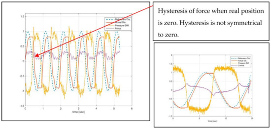
Figure 10.
Behavior of flexible joint (model) without control offset, 2 Hz (±1 V), K = 1, input signal and friction in model of flexible joint.
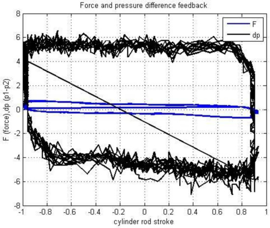
Figure 11.
Force and pressure difference feedback.
This experimental technology to develop a robust control algorithm is an alternative to numerical models [11]. Additionally, this concept of control with offset can support situations during failure (asymmetry load–non-symmetrical elastic hysteresis of flexible joint) with on-line offset value changing. For this reason, adequate monitoring is necessary [12]. The nozzle is held by a ring of alternate layers of molded elastomer and spherically formed sheet metals. It is a complex load which is difficult to model for linear or non-linear mathematical models. With a real model of a flexible joint, we can preliminarily estimate some control algorithms. In this case, we tested a simple control algorithm. The criterion for quality estimation is force hysteresis compensation. If we have symmetrical hysteresis, it is considered to be a better situation for control compensation then a situation with non-symmetrical hysteresis—especially by relay non-linearity. The relay non-linearity is defined by control offset defined by non-symmetrical directional control valve pressure gain.
Based on the results of experiments, it is possible to compare the positional response of an actuator in the case of inertial and flexible loads being combined, and in the case when inertial load can be neglected. In this way, it is possible to estimate when the internal friction in a flexible joint can have a positive influence on the stability of the operations of an actuator system, and when it cannot. Previous analysis shows the parameters of an electro hydraulic system which require special attention.
4. Non-Linear and Linear Description of Flow Characteristics of Distributor and Flexible Load
The classical approach is based on the proximity of the work point to nominal, around which the linearization of a distributor’s flow characteristic is performed, justifying or not the linearization of the distributor’s flow characteristics (which is mathematically square root function type). This paper presents another analysis, of how flexible load affects the way in which distributor’s flow characteristics are being described. This analysis shows the boundary/limit of modeled and un-modeled dynamics. Flexible load is presented as an ideal spring. In the case of dominant position load, the following dependency is defined, after the application of mathematical formalisms for determination of work force:
Work with non-linear description of the static characteristic of a distributor:
In the case of position load and linear description of the static characteristic of a distributor, the work force is:
Quotient ratio of works is in the form of
The previous integral can be solved only numerically, and in Figure 12, the dependency of function β = β(α) is presented:
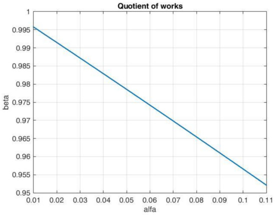
Figure 12.
Graph of numerical solution of the integral in Equation (16).
Previous consideration presents a mathematical study of the influence of the static characteristic of the distributor in various methods of modeling when we want to see the effect of flow oscillations on the quality of the operation of the actuator system. It is clear that the described problem—non-linear or linear description—does not exist in actuators with dominant positional load.
5. Conclusions
It is demonstrated that some results from the application of automated control theory can be used as criteria for the general design of a flexible nozzle in the initial phases of its design, especially when parameters of a flexible joint and an actuator are being defined. The result of experiments in the frame of this work indicate that we can make a poor identification with the model of a flexible nozzle, which can define only the main non-linearity. This nonlinearity which can be defined according to the static characteristics of the actuation system can be compensated by P control law with offset. Thus, the mathematical model of flexible load for control synthesis is not necessary. The experiments also indicate that cascade control with force feedback is not necessary if the force and position are in variation with the same velocity. This is extremely important, considering that there can be an ideally synthesized and adjusted control algorithm for the actuator system, yet the very system could be poorly designed with a great number of deficiencies. The significance of this approach is also in the fact that available solutions show the application of very simple linear mathematical description of the structure of electro hydraulic systems used for control synthesis [13,14,15,16,17], meaning that there are no structural deficiencies in the design.
The elaboration in this paper showed that by accepting the approach to present the system at a structural level (after the initial design phase), with non-linearity of dead band type (which includes all the phenomena described through hysteresis), it is very efficient to synthesize the control by defining proportional gain plus offset, which need to be determined experimentally by recording the difference (non-symmetry, pressure difference) in amplifications per pressure as a good solution for the compensation of nonlinearities. Thus, it is possible to synthesize the control algorithm without a mathematical model. All control improvements must be under the check of energy-saving criterion [18,19], generally for electro hydraulic systems for flight control.
This paper describes the consideration of non-linearity influences, mathematical (static characteristic of directional control valve), inherent static (velocity and acceleration saturation, friction, and elastic hysteresis) and control non-linearity for control synthesis without the direct modeling and simulation of electro-hydraulic actuator structure.
Author Contributions
Dragan Nauparac and Marko Milos conceived and designed the experiments; Dragan Nauparac performed the experiments; Dragan Nauparac and Dragan Prsic analyzed the data; Dragan Prsic contributed reagents/materials/analysis tools; Dragan Nauparac wrote the paper.
Conflicts of Interest
The authors declare no conflict of interest.
References
- Nauparac, D.; Prsic, D.; Milos, M. Design Selection of Adequate Control Algorithm for Electro-hydraulic Actuator Applied on Rocket Engine Flexible Nozzle Thrust Vector Control. In Proceedings of the 14th ITI Symposium, Dresden, Germany, 30 November–1 December 2011. [Google Scholar]
- Situm, Z. Force and position control of a hydraulic presses. VENTIL 2011, 17, 314–320. [Google Scholar]
- Sivaselvan, M.V.; Reihorn, A.M. Dynamic Force Control with Hydraulic Actuators Using Added Compliance and Displacement Compensation. Earthq. Eng. Struct. Dyn. 2008, 37, 1785–1800. [Google Scholar] [CrossRef]
- Jelali, M.; Kroll, A. Hydraulic Servo-Systems, Modeling, Identification and Control; Springer: Berlin, Germany, 2003. [Google Scholar]
- Reinhold, V. Nonlinear Control Engineering (Describing Function and Analysis Design); VNR Company: New York, NY, USA, 1982. [Google Scholar]
- Yan, J.; Li, B.; Ling, H.; Chen, H.; Zhang, M. Nonlinear State Space Modeling and System Identification for Electro hydraulic control. Math. Probl. Eng. 2013, 2013, 973903. [Google Scholar] [CrossRef]
- Fielding, C.; Flux, P. Non-linearities in flight control systems. Aeronaut. J. 2005, 107, 673–686. [Google Scholar]
- SimscapeTM. 2012 The MathWorks. Available online: www.mathworks.com (assessed on 02 April 2018).
- Sieteanu, T.; Giuclea, M.; Mitu, A.M. An Analytical approach for approximation of experimental hysteretic loops by Bouc-Wen model. Proc. Rom. Acad. Ser. A 2009, 10, 4354. [Google Scholar]
- Borello, L.; Villero, G. Proposals and Comparative Evaluation of Synthetic Nonlinear models in flight control simulation. In Proceedings of the ICAS 2002 Congress, Toronto, ON, Canada, 8–13 September 2002. [Google Scholar]
- Borello, L.; Villero, G.; Dalla Vedova, M.D.L. Flaps Failure and Aircraft Controllability: Developments in Asymmetry Monitoring Techniques. J. Mech. Sci. Technol. 2014, 28, 4593–4603. [Google Scholar] [CrossRef]
- Borello, L.; Villero, G.; Dalla Vedova, M.D.L. New asymmetry monitoring techniques. Aerosp. Sci. Technol. 2009, 13, 475–497. [Google Scholar] [CrossRef]
- Bernard, M. Vega Missionization and Post Flight Analyses. Ph.D. Thesis, University of Roma, Rome, Italy, December 2010. [Google Scholar]
- Schinstock, D.; Scott, D.; Haskew, T.A. Modeling and Estimation for Electromechanical Thrust Vector Control of Rocket Engines. J. Propuls. Power 1998, 14, 440–446. [Google Scholar] [CrossRef]
- Lampani, L.; Angelini, F.; Bernabei, M.; Marocco, R.; Fabrizi, M.; Gaudenezi, P. Finite Eelement Analysis of a Solid booster Flexible bearing Joint for Thrust Vector Control. J. Aerosp. Sci. 2012, 91, 53–61. [Google Scholar]
- Prilipov, A.V. Razrabotka Metodiki Rasceta Gazogidravliceskoga Istocnika Rulevogo Privoda Upravleniya Povorotnim Soplom Putem Postroenia Epyri Soprjazeniya Raspolagaemoj i Potrebnoj Mocnostei; MAI: Moskva, Russia, 2010. [Google Scholar]
- Si, L.; Wang, Z.; Liu, X.; Zhang, L. A Novel Compound Control Method for Hydraulically Driven Shearer Drum Lifting. J. Control Sci. Eng. 2014, 2014, 691787. [Google Scholar] [CrossRef]
- Shen, W.; Jiang, J.; Su, X.; Karimi, H. Energy-Saving Analysis of Hydraulic Hybrid Excavator Based on Common Pressure Rail. Sci. World J. 2013, 2013, 560694. [Google Scholar] [CrossRef] [PubMed]
- Nauparac, D.; Prsic, D.; Milos, M.; Samardzic, M.; Isakovic, J. Design Criterion to Select Adequate Control Algorithm for Electro-Hydraulic Actuator Applied to Rocket Engine Flexible Nozzle Thrust Vector Control Under specific Load, FME Transaction. FME Trans. 2013, 41, 33–40. [Google Scholar]
© 2018 by the authors. Licensee MDPI, Basel, Switzerland. This article is an open access article distributed under the terms and conditions of the Creative Commons Attribution (CC BY) license (http://creativecommons.org/licenses/by/4.0/).