Review

Piezoelectric Motors, an Overview

Physik Instrumente GmbH & Co. KG, Auf der Roemerstrasse, 1, Karlsruhe 76228, Germany
*
Author to whom correspondence should be addressed.
Actuators 2016, 5(1), 6; https://doi.org/10.3390/act5010006
Submission received: 1 December 2015 / Revised: 1 February 2016 / Accepted: 17 February 2016 / Published: 26 February 2016
(This article belongs to the Special Issue Piezoelectric Actuators)

Abstract

:
Piezoelectric motors are used in many industrial and commercial applications. Various piezoelectric motors are available in the market. All of the piezoelectric motors use the inverse piezoelectric effect, where microscopically small oscillatory motions are converted into continuous or stepping rotary or linear motions. Methods of obtaining long moving distance have various drive and functional principles that make these motors categorized into three groups: resonance-drive (piezoelectric ultrasonic motors), inertia-drive, and piezo-walk-drive. In this review, a comprehensive summary of piezoelectric motors, with their classification from initial idea to recent progress, is presented. This review also includes some of the industrial and commercial applications of piezoelectric motors that are presently available in the market as actuators.

1. Introduction

Generation of electrical charge on certain materials in response to applied mechanical stress is known as the piezoelectric effect. The same materials have the ability to convert electrical energy into mechanical motion directly and that is known as the inverse piezoelectric effect. The range of mechanical movement generated on a piezoelectric element is very small, from 1 µm to 100 µm. This small movement is the key for obtaining extremely high precision positioning in the order of 1.0 nm. Piezoelectric motors are the devices that generate unlimited rotary or linear movements by harvesting this very small motion.
By the different drive and functional principles for generating unlimited rotary or linear movement, piezoelectric motors can be classified into three categories: (1) resonance drive (Ultrasonic motor), where vibration at ultrasonic frequency range on an oscillating element is transferred to a moving element through frictional coupling; (2) inertia-drives, where a movement is generated by speed dependent friction coefficient; and (3) piezo-walk-drives, where various piezo actuators are used for alternatively clamping and shifting a moving element. The actuators in these motors operate in a quasi-static mode.

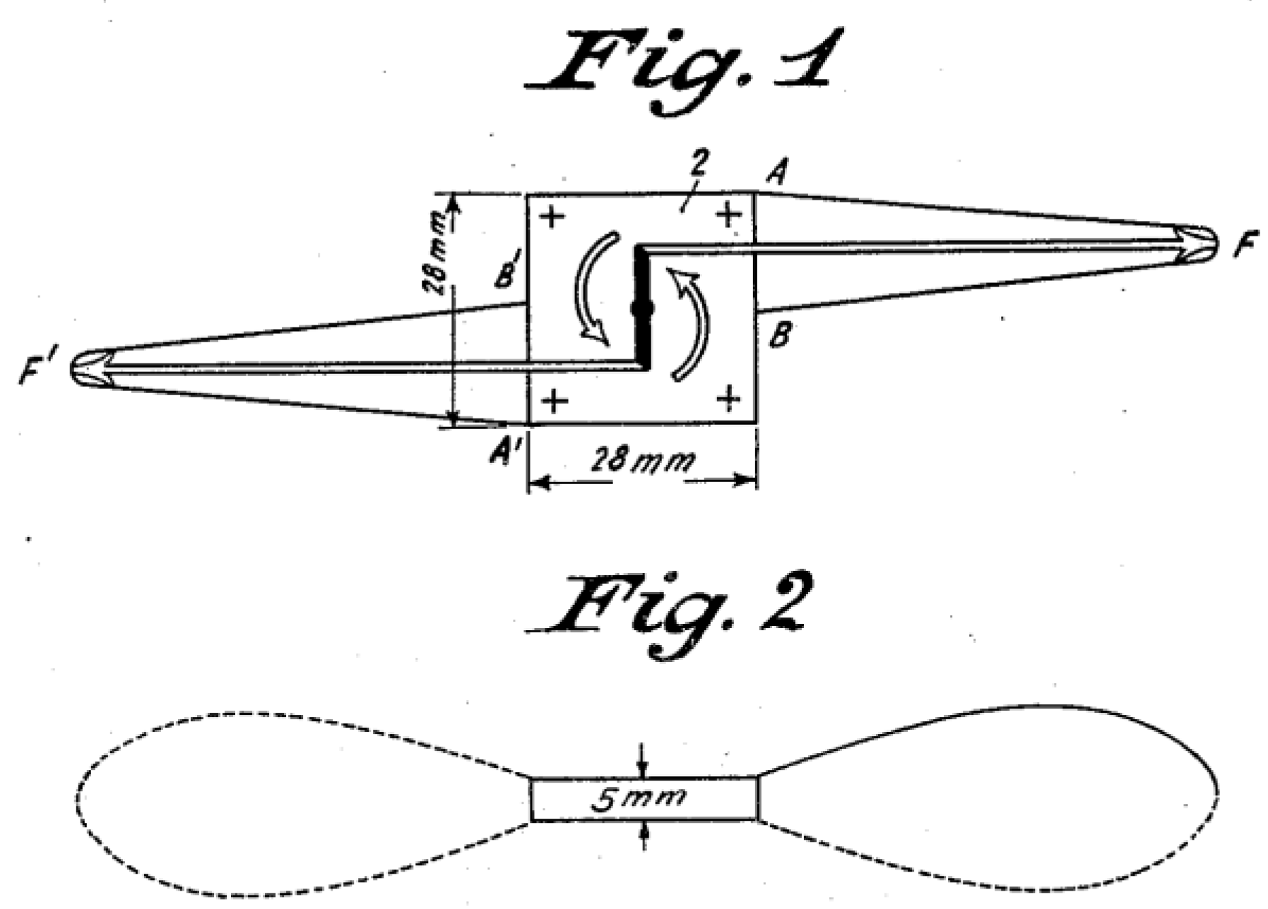
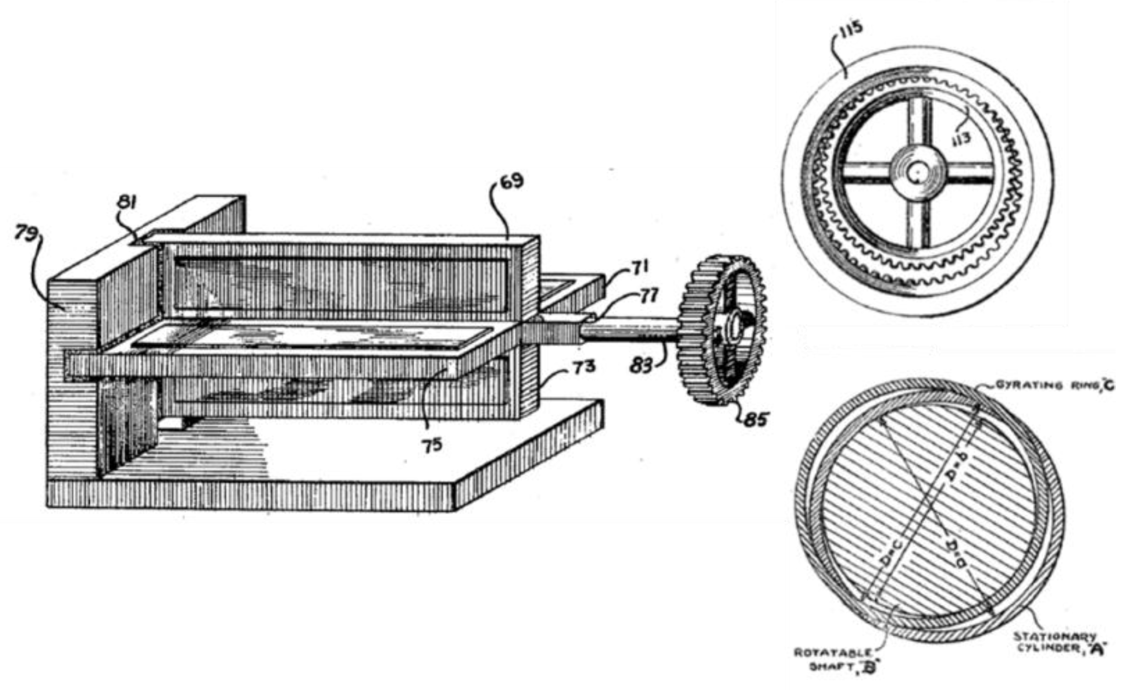
2. Early Structures of Piezoelectric Motors

Since the discovery of piezoelectricity, there have been several attempts to obtain longer mechanical motion using the inverse piezoelectric effect [1,2,3,4]. In a US patent titled “Converting electrical oscillations into mechanical movement” filed by Meissner in 1927 [1]. The structure of the motor described in this patent consists of a piezoelectric plate with a center-attached shaft and asymmetrically-attached two lever arms. When a driving signal is applied through two conductive plates to top and bottom surfaces of the piezoelectric plate, torsional vibration modes are excited due to asymmetrically-attached lever arms. It seems that the conductive plates are not only used for applying a driving oscillatory signal, but also to create a frictional coupling. Generated vibration on the piezoelectric plate at a suitable torsional mode causes the piezoelectric plate and the center shaft to rotate (Figure 1).
The piezoelectric motor developed by Williams and Brown in 1942 [2] proposed a structure to convert gyratory (hula-hoop) motion generated by the arrangement of multiple piezoelectric elements into a rotary motion through a gear structure. In the same patent, a structure to convert gyratory motion to a rotary motion by frictional coupling was also proposed. The necessary pre-stressing force to increase frictional coupling was applied through magnetic attraction force (Figure 2).
A systematic study of piezoelectric ultrasonic motors in the former Soviet Union can be seen after the introduction of a piezoelectric motor by Lavrinenko in 1965 [3]. This motor consists of a piezoelectric plate pressed against a rotor and operates unidirectionally (Figure 3). At about the same time, another unidirectional piezoelectric motor structure using a cylindrical piezoelectric element and a spinning rod with attached coupler was proposed by Tehon in the USA [4]. Following these initial ideas, several other motor structures have been proposed by Wischnewskiy [5]. Most of these early structures are unidirectional, which means only one mode on a vibrator is excited. One, or multiple, elastic vibration couplers oriented obliquely and attached either on a spinning element or on a vibrating element transfer the vibration into a rotating element. In the early structures, not only rectangular piezoelectric plates, of which longitudinal modes were excited, but also circular piezoelectric plates were used to convert radial vibratory motion into tangential motion via angularly-attached lamina (Figure 4) [5].
Further investigations of piezoelectric motors led to a recognition of fundamental design principles that following structures could be operated bidirectional [6,7,8]. As a result of these studies by various people, a book on piezoelectric motor was written in 1981 by Bansevicius and Ragulsky [9]. After the translation of this book into English language in 1988 [10], piezoelectric motors studied in former Soviet Union were recognized more.
In the meantime, to fulfill the needs for precise positioning, other piezoelectric devices were proposed using step motion of multiple piezoelectric elements. A structure called an incremental feeding mechanism proposed by Stibitz in 1962 was the first structure that could be considered to function according to piezo-walk and inertia drive principles [11]. Even though the design is using three magnetostrictive actuators that are driven simultaneously; in the same structure, there is a description for the possibility of using piezoelectric actuators to make a small incremental motion. The magnitude of the driving signals for each actuator has a typical characteristic of a slow increase and a fast decrease with a certain phase difference between them (Figure 5).

3. Resonance-Drive (Piezoelectric Ultrasonic Motors)

Among the piezoelectric motors, resonance-drive (or ultrasonic) motors have been the most studied actuators [9,10,12,13,14,15]. Any stator element in a piezoelectric ultrasonic motor is a composite structure, in which piezoelectric and elastic elements are combined in various forms. These elastic elements can have different functions. They can simply act as a friction tip or vibration coupler to convert generated displacement from one direction to another.
When we were classifying resonance-drive type motors we tried to find answers to the following statements:
  • Number of vibrating elements that generate needed microscopic motion,
  • Number of mechanical modes that are excited at the operating frequency of the vibrating element,
  • Number of driving signals applied to a vibrating element,
  • Full or partial drive of a piezoelectric element in a vibrator, and
  • Unidirectional or bidirectional motion, if bidirectional; the method of changing direction such as frequency, phase, or excited part.
We tabulated the answers of the above statements in Table 1.
Since all of the ultrasonic motors operate by exciting one or more than one mechanical resonance modes of their stator elements, these motors can be categorized according to the number of resonance modes excited on a stator element. Actually, any resonance type piezoelectric motor can be grouped into two. The generated motion is either oblique or elliptical, and these motions can be generated in various ways. On a stator element, if only one mechanical resonance mode at the operating frequency is excited, then this motor can be called a single-mode excitation type. If more than one mechanical resonance mode at the motor operating frequency is excited, then the motor can be called a multi-mode excitation type. In order to generate an elliptical motion on the vibrating element, there needs to be motion in two orthogonal directions with a certain phase difference.

3.1. Single-Mode Excitation Type

3.1.1. Piezoelectric Element Is Fully Driven

In these types of motors, the motion generated on a vibrating element is in the oblique direction. The vibrating element is excited by one driving source and the piezoelectric element in the motor is fully driven. Exciting only one resonance mode is enough to generate a motion. One can orient either vibrating element or moving element with a tilt angle so that this direction of microscopic motion at the contact point to have normal and tangential components at the interface. The other method to obtain oblique motion at the interface is the use of an attached vibration coupler or lamina [5,8,10,16,17]. Even though the motor is unidirectional, one can use two of these vibrating elements to obtain bidirectional motion [18,19].

3.1.2. Piezoelectric Element Is Partially Driven

When a motor is single-mode excitation type and bidirectional, the moving direction can be changed by partial driving of a piezoelectric element. A well–known piezoelectric ultrasonic motor fitting to this category was developed at Physik Instrumente (PI) [20,21,22]. The motor is manufactured under a trade name of “PIline®”. The vibrating element in this motor is a rectangular type piezoelectric plate with a certain length to width ratio. Electrodes on one surface of the plate are segmented into two sections in width direction and a friction tip is attached at the middle of one side surface (Figure 6). When one half of the plate is driven with an electrical signal, a planar (or radial) mode resonance frequency of the driven section is excited. The friction tip and unexcited other half of the plate function like a perturbation mass. As a result, an oblique motion at the tip of the friction tip causes the sliding element to make a linear or rotary motion. A recent structure, where a linked twin square plate vibrator proposed by Yokoyama, functions according to the same principle [23].
The single-mode excitation type resonant piezoelectric motor (PIline®) with its simple structure and fast dynamic response has been used in various applications. One such application is in a theodolite. A theodolite [24] is a precision instrument on which a movable telescope is mounted for measuring angles in the horizontal and vertical planes. Two pairs of PIline® motors are integrated into a theodolite structure, which can provide rotary motions in two perpendicular axes. The PIline® motors have been also used in various medical devices such as high-resolution optical coherence tomography (OCT) scanners and controllers for laser beam scanners used for eye surgery [22].
The same principle of partial driving was applied to a cylindrical piezoelectric element and again by exciting the segmented electrodes on the piezoelectric cylindrical element partially, an oblique motion on friction tips was obtained (Figure 7). Changing the driven part changes the direction of the oblique motion and, thus, the motor direction.
Another well-known rotary version of a single-mode excitation type ultrasonic motor was developed by Takano et al. [25] using a piezoelectric ring with 12 segmented electrodes. Driving only six of the 12 electrodes on a circular piezoelectric element at one time excites a single flexural mode on the stator element. This flexure deformation of the stator element causes three of the corresponding friction tips (projections) to make an oblique motion. The oblique motion on the friction tips causes the rotor to spin.
A motor proposed by He [26] is also fitting to this category, where a piezoelectric tube with four side electrodes with end teeth is used as the vibrator of this motor. An electrical signal is applied in between one pair of surface electrodes (from half of the surface) to the other pair of surface electrodes. This driving excites the single bending mode. Specially-located teeth apply an oblique impact to the surface of spinning elements at both ends, thus causing the rotor to spin.

3.2. Multi-Mode Excitation-Type Motors

Unlike single-mode excitation type ultrasonic motors, where the motion at contact point is in oblique direction, the motion at the contact point of multi-mode excitation type motors is elliptical. The elliptical motion is generated by exciting two orthogonal mechanical resonance modes. These orthogonal modes can be excited by one or multiple driving sources. A piezoelectric element (or elements) in a vibrator can be fully or partially driven. One can group multi-mode excitation-type motors according to the number of driving sources and control methods used for direction change.
  • One Driving Source
    • -Piezoelectric element is fully driven
      • -Frequency change controls the direction
    • -Piezoelectric element is partially driven
      • -Driven part controls the direction
  • Multiple Driving Sources
    • -Piezoelectric element is fully driven
      • -Phase change between the driving sources controls the direction

3.2.1. One Driving Source (Frequency Change Controls the Direction)

In a multi-mode excitation-type ultrasonic motor, if all of the piezoelectric volume in a stator element is electrically driven with one AC source, and if more than one mechanical resonance modes are excited, the direction of the sliding or rotating element can only be changed when the frequency of the input electrical signal is tuned to a different orthogonal mechanical resonance mode. A good example fitting to this category is the motor developed by Elliptec [27]. A recent motor structure that uses the same operating principle was proposed by Xing et al. [28]. This motor is using a metal tube, on which a piezoelectric plate is attached on to the flattened side surface. The main advantage of these motors is the use of only two wires for driving. However, the direction dependent speed-driving voltage dependency could increase the complexity of the control electronics. The initial idea fitting to this type of motor structure was proposed by Uchino in 1988 [29].

3.2.2. One Driving Source (Driven Part Controls the Direction)

In these multi-mode excitation-type motors, piezoelectric element in a vibrator is partially driven with one driving source. Early structures of these motors were proposed by Wischnewskiy [6] and Bansiavichus [7]. Electrodes on one surface of a rectangular-shaped piezoelectric plate are divided into four equal small rectangles as shown in Figure 8. Orthogonal longitudinal and bending modes are excited at the same time by exciting only two electrodes that are located diagonally. The direction of the motor can be controlled by driving the other diagonally-located electrodes.
The ultrasonic motor from Nanomotion Ltd. also uses the same first longitudinal and the second flexural modes in width direction. The pusher in this motor is located at the end of the piezoelectric plate [30].
Piezoelectric motors can be made using non-magnetic materials and piezoelectric elements do not generate magnetic fields. Thus, these motors can be made non-magnetic and magnetic-insensitive, which is an advantage in medical applications, such as for magnetic resonance tomography (MRT). Piezoelectric motors manufactured by Nanomotion are used in surgical robots [31].
Another multi-mode excitation type motor using piezoelectric plate-type stator element was developed by Samsung Electro-Mechanics and this motor has been used for auto-focus applications in phone cameras [32,33]. Even though the basic operating principle is the same as the other multi-mode excitation-type motors, dilatational and thickness bending modes of a piezoelectric plate were combined and the miniature stator element was directly manufactured in multilayer form. On such a small actuator, which has a dimensions of 2.5 × 2 × 0.6 mm, two cylindrical friction elements are attached into two indented surfaces (Figure 9). This motor is probably a good example to show that ultrasonic motors can be manufactured in large quantities with a similar cost to their electromagnetic counterparts. Indeed, the manufacturing process of this motor is very similar to the multi-layer ceramic capacitor (MLCC) manufacturing method.
An ultrasonic motor developed at the Penn-State University is another example for the multi-mode excitation type rotary motors [34]. The two orthogonal modes in this motor are the two bending modes of a metal cylinder. The stator of the motor consists of a metal cylinder on which two piezoelectric plates are attached on flattened surfaces. When one piezoelectric plate is electrically driven, a wobbling motion on the cylinder is generated because two bending modes of the cylinder are excited at the same time. This motion causes the rotor to spin. When the other piezoelectric plate is electrically driven, the direction of wobbling motion is changed (Figure 10).

3.2.3. Multiple Driving Sources (Phase Change between the Driving Sources Controls the Direction)

To generate an elliptical motion on a vibrating stator element, it would be useless to drive this element with two sources with a phase difference between them. Unless the vibrating stator element has two orthogonal modes and the resonance frequencies of these modes are equal or close enough. In case of these two orthogonal modes resonance frequencies are not equal; only one mode can be excited efficiently. Ultrasonic motors that are known in literature as travelling wave types could be considered as a multi-mode excitation type. A flexural vibration mode on a circular piezoelectric ring or disk has symmetry in every direction. Segmented electrodes on a piezoelectric element divide the surface into two groups. These two electrode groups are excited with two signals and each of these signals excite two identical flexural modes. Since there is a 90 degrees phase difference between the driving signals, each point on the stator surface makes an elliptical motion. The resulting motion is nothing but a travelling wave on this circular stator element. Ultrasonic motors using circular stator elements and operate the abovementioned principle found the first commercial applications in 80 s in Japan (Figure 11) [35,36]. A famous application of traveling wave type ultrasonic motor is for automatic focus systems in cameras used by Canon [37,38,39].
The motor proposed by Wischnewskiy is an example of a multi-mode excitation-type motor, where a piezoelectric plate with segmented electrodes and corresponding orthogonal resonance modes are driven with two phase signals [40]. On the piezoelectric plate the larger electrode area in the middle is responsible for generating longitudinal mode, and four small electrode areas are responsible for exciting bending modes. Each input signal excites the corresponding orthogonal mode and phase difference of the two signals control the direction of the elliptical motion at the friction tip and, thus, the direction of the slider (Figure 12).
When multiple piezoelectric elements are combined in a stator element, motion generated by each vibrator should be orthogonal [41]. If the motions generated by these vibrators are identical then the vibrators need to be oriented orthogonally [42] (Figure 13). Integrating two vibrating elements by orienting them 90 degrees to each other was used by various researchers working on piezoelectric motors [43,44,45].
Externally hammering an elastic ring element by obliquely-oriented multiple longitudinal actuators to generate a travelling wave on an elastic ring could also be considered as a multi-mode excitation-type motor [46]. Since hammering points cause two identical Eigen modes to be excited at the same time, the phase difference causes contact points to make elliptical motions.
The ultrasonic motors using symmetric cylindrical, circular, or flat square structures, and using two identical orthogonal modes, should be considered as multi-mode excitation-types. Motors using piezoelectric cylinders with four segmented electrodes on outside surface and uniform metallization to its inner surface are excited with four phase signals (sine, cosine, -sine, -cosine). In this structure, two bending modes that are orthogonal are excited and the phase difference causes the hula hoop motion [47]. The same principle was applied to a squiggle motor manufactured by New Scale [48], where a metal tube with attached four piezoelectric plates and treaded at the inner side made a screw-type spinning element to cause a linear motion.
A cylindrical structure with embedded piezoelectric ring elements at a suitable position is commonly used as a stator for resonance-type piezoelectric motors. All of these motors are using two orthogonal and identical first bending modes including the structure proposed by Kurosawa in 1989 [49]. Commercially manufactured second-generation ultrasonic motor manufactured by Canon for lens positioning applications also has the same structure [39], where the piezoelectric ring element and the mechanical part in the motor is manufactured with a highly-specialized manufacturing technique [50].
A hula-hoop motion can be obtained on a piezoelectric square or circular plate by dividing one surface electrode into four equal segments and driving with four phase signals [37]. The same hula-hoop motion can be generated by using symmetric circular or square plates when both the top and bottom surfaces have two identical conductive electrodes that are dividing the piezoelectric element into two equal regions. If a signal is applied in between two divided surface electrodes, in-plane modes can be generated. Since electrode pairs are rotated by 90 degrees on the other surface, the same in-plane modes can be excited in orthogonal direction. When one source drives the electrodes on the top surface, and the other drives the electrodes on the bottom surface, these identical modes in the orthogonal direction are excited at the same time. When the two signals have 90 degrees out of phase, the resulting motion is nothing but a hula-hoop motion [51]. Any identical in-plane motion can be controlled independently, which means the shape of the microscopic elliptical motion at the contact point is fully controllable by magnitude and phase differences of the driving signals (Figure 14).

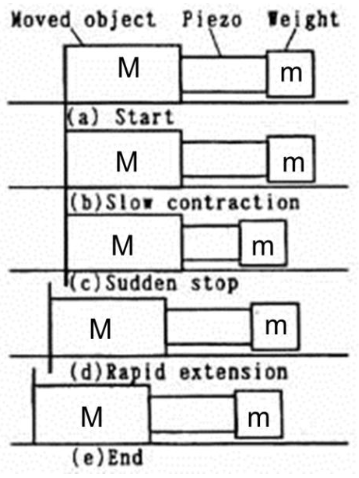
4. Inertia-Drive-Type Piezoelectric Motors

The first practical inertia-drive (stick-slip) structure was proposed by Pohl in 1986 [52], where a piezoelectric cylinder is embedded into a four-bar mechanism. One side of the four-bar was attached to a base and a sliding mass is attached at the other parallel bar. When the actuator is driven with a saw-tooth waveform signal, the attached mass moves together with the bar during the slow expanding period of the saw-tooth signal (sticking) and left behind during the fast contraction period of the signal (slipping). Repeating the cyclic motions make the attached mass move continuously. When the electric field makes the piezoelectric element expand quickly and contract slowly, the attached mass moves in the opposite direction. This mechanism was applied for a precise multi-degrees of motion positioning device applications for an atomic force microscope.
About the same time, another impact drive mechanism was proposed by Higuchi [53]. A moving mass is placed on a base plate and held by frictional force acting between the base plate and the moving mass. A piezoelectric element is attached on one side of the moving mass and a weight is attached at the other side of the piezoelectric element. When an electric field is applied on the piezoelectric element, a rapid expansion of the piezoelectric element creates an acceleration causing the moving mass to win the static friction (slip) so both masses move in opposite directions. During the slow contraction time of the piezoelectric element, the acceleration on the moving mass cannot win against the static friction so only the weight moves (stick). At the end of one cyclic motion, a microscopic movement on the moving mass is obtained (Figure 15).
In the later version of the impact-drive mechanism, a piezoelectric multilayer actuator is attached in between a body mass and a rod, on which a sliding element (inertia mass) is attached with a spring force creating a frictional coupling between the rod and the inertia mass. Even if the actuator is generating a displacement in the longitudinal direction, this motion on the rod is actually in a tangential direction to the attached moving inertia mass. This motor had been commercialized by Konica Minolta to use for camera applications, such as auto-focus, zoom, and image stabilization functions [54,55].
Almost all of the inertia-drive type motors are using the above described principle with various ways of generating tangential displacement at the interface in between a stationary and a moving element. A displacement in the tangential direction can be generated in two ways. One is direct generation by using longitudinal [53,54,55], transverse [56] or shear [57] deformations of the piezoelectric material. The other way is by converting generated displacement from piezoelectric element into tangential direction at the interface by using flexure or leverage mechanisms [58,59,60,61]. Presently, there are companies producing high-precision stages using inertia drive-type motors [58,59,60,61,62,63,64].
There are applications that use inertia drive motors for microscopy and biotechnology research such as cell manipulation. Piezoelectric inertia drive motors have been used for both optical and scanning probe microscopes successfully in vacuum environments [65,66].
Recently-proposed inertia-drive motor structures can operate at resonance frequency [67,68,69,70]. Saw-tooth-like motion to generate stick and slip actions is created by exciting two resonance modes at two different frequencies. The second-mode resonance frequency of the vibrating element in these motors is two times higher than the first-mode resonance frequency. These two resonance modes are excited by either a square wave with a duty ratio smaller than 50% or adding two sine signals. The resulting tangential motion is fast acceleration to slip by overcoming friction force and slow deceleration to stick or vice versa.

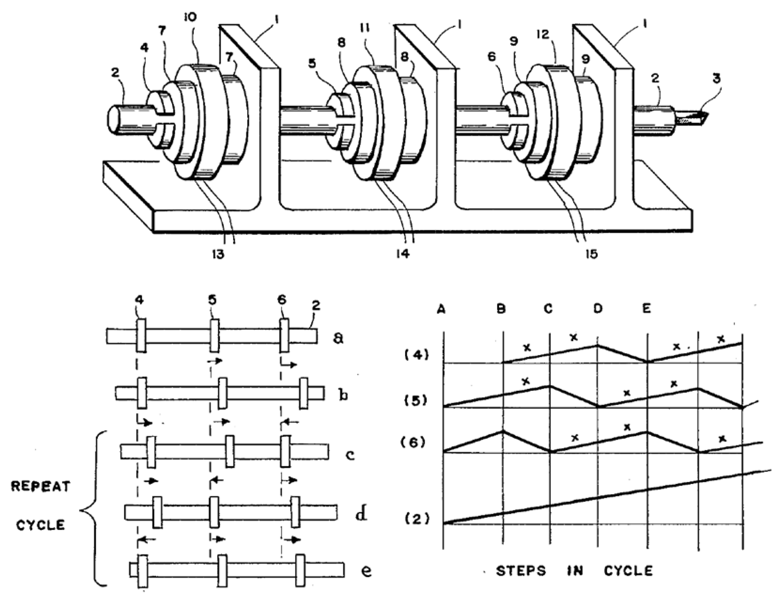
5. Piezo-Walk-Drive-Type Piezoelectric Motors

For positioning in a long range of motion, a structure proposed by Brisbane in 1965 operates based on the piezo walk-drive principle [71]. In this structure, two piezoelectric disc shaped plates are attached to a hollow cylinder at both ends. While the piezoelectric disks function as clamping actuators, the hollow cylinder acts as a moving actuator. The whole structure is placed in a retaining cylinder as shown in Figure 16. One period of motion sequence of this motor is as follows; assuming one of the clamping actuators (4) is in the clamp position and the other (5) is in the release position, the step is the moving actuator (6) expanding and making a microscopic movement. Following that the clamping actuator (5), that is in the release position, clamps and then the other clamping actuator (4) releases. At this time, the moving actuator (6) contracts and makes another microscopic movement. One period of motion sequence is completed when the clamping actuator (4) clamps and then the other clamping actuator (5) releases.
A similar structure, functioning with the same principle, was proposed by Galutva et al. in 1970 [72]. In this structure, three multilayer piezoelectric actuators were placed inside two parallel guiding plates. The actuator in the middle makes a microscopic stepping motion parallel to the guiding plates and the other end actuators make the structure to be clamped inside the two guiding plates simultaneously. In this structure, wedge-shaped elements eliminate manufacturing tolerances and apply pre-stressing forces on the piezoelectric actuators.
A well-known piezo-motor in this category is the Inchworm® motor proposed by Burleigh Instruments, Inc. in 1974 [73]. Multiple piezoelectric actuators make synchronous motion by repeating “release-clamp-move and clamp-release-move” steps to produce a movement.
A piezoelectric motor using four legs that are pressed against a slider is developed by Marth et al. in 1995 [74]. Each drive element is a piezoelectric bimorph that is electrically isolated and can be controlled independently. Deformation in length and bending direction of the bimorph element simultaneously causes the pressed slider to make a linear motion. A piezoelectric stepper motor from the Swedish company Piezo Motor Uppsala AB operates according to the same principle [75].
The manufactured piezo-walk drive motor at PI has integrated clamping and moving actuators (Figure 17). Shear actuators [76] that are responsible to make micro-stepping are attached at the tip of the longitudinal actuators that are responsible for clamping action. Excitation sequence is the same as the other piezo-walk drive motors, assuming actuator pairs (A) are in release and pairs (B) are in clamping condition. The sequence could continue as follow: Clamp (A) - release (B) - move (A) - clamp (B) - release (A) - move (B).
The high force and high stiffness of the piezo-walk drive motor with its high resolution (< 1 nm in open-loop), self-locking at rest, vacuum compatibility, and non-magnetic features, make this motor useful in applications in research, semiconductor processing, such as lithography, and hexapod robots used for computer-aided surgery. Nextline® piezo-walk drive motors developed and manufactured at PI also have two modes of operation; analogue mode for short travel range and step mode for long travel range [22].
Recently, we can see that particle accelerator devices also benefit from non-magnetic and compactness features of piezoelectric motors. Particle accelerators, such as a cyclotron, are devices producing radioisotopes that are used in medical therapy, imaging, and research in various industrial and medical applications. In addition to the electric and magnetic field generating systems in a closed environment (chamber), there are also mechanical devices in the chamber that need to be moved or adjusted at a desired position so that charged particles are incident thereon. A US patent was granted for a particle accelerator in which piezoelectric motors are used to move or adjust mechanical devices in it [77].

6. Discussions

In piezoelectric walk-drive-type motors, the actuators are responsible for clamping and releasing actions simultaneously, and at least one actuator is responsible for the moving action. In a piezoelectric inertia-drive-type motor, there is only tangential back and forth motions at the interface of sliding and fixed elements within one period of time. In one direction of the tangential motion, inertia force acting on the sliding element is smaller than the friction force so the sliding element sticks to the fixed element. In the other direction of tangential motion, inertia force action on the sliding element is larger than the friction force, so the sliding element slips and makes a microscopic step.
In a single mode excitation type piezoelectric ultrasonic motor, there is an oblique motion at the interface. Since this oblique motion has components in tangential and normal directions, a net microscopic motion is obtained. In a multi-mode excitation-type piezoelectric ultrasonic motor, there is an elliptical motion at the interface, which means there are displacements in two orthogonal directions at the contact point. This elliptical motion causes the sliding element to make a microscopic motion.
Even though there are many piezoelectric motor designs functioning above mentioned operating principles, the number of commercially successful inventions is limited. This indicates that the described operating principles in those inventions were not sufficient to make commercially viable motors. There are contradictory conditions in piezoelectric motors that need to be carefully analyzed for commercially successful designs.
Holding of displacement generating or vibrating element: a vibrating element in a resonance-drive-type piezoelectric motor need to be held as tightly as possible so that a precise motion without any hysteresis can be obtained. However, tight holding of a vibrating element may suppress useful displacements or vibrations. At the same time, to generate enough vibration with sufficient magnitude, the vibrating element needs to move freely so that vibration on a stator element can be transferred to a sliding or rotating element. Therefore, holding of a vibrating element in a resonance-drive type piezoelectric motor could create a contradictory condition and increases complexity of the motor structure. If a stator element allowing tight holding means that there are nodal positions on it. In this case, it could be considered as a good design.
Friction contact: on a contact surface for low wearing, a smooth and slippery surface is desirable. At the same time, for an efficient motion transfer from vibrating to sliding element, a high friction contact is necessary. Thus, these two parameters, slippery surface for low wear and friction contact, work against each other. Moreover, the nonlinear nature of tribology makes the contact mechanics to be even more challenging.
Pre-stress on vibrating element: when a piezoelectric motor is integrated in a system, in order to increase force transfer, the vibrating element needs to be pre-stressed against the sliding element. While pre-stress force may disturb the guiding mechanism of the slider, the vibration of the stator element could initiate undesirable vibrations on the integrated system.
Additionally, temperature dependency of piezoelectric elements used in a motor requires the drive electronics to have special features.
In short, success of a piezoelectric motor is hidden in the details. Aforementioned issues require know-how from different engineering disciplines to be used for the design of piezoelectric motors. One needs to analyze these issues and apply them properly in a design for commercially viable piezoelectric motors.
Indeed, modeling of contact mechanics and control of piezoelectric motors to clarify the nature of the operating principal and to optimize performance has always been an important study area in the field of piezoelectric motors [78,79,80,81,82,83,84,85,86,87].
Distinguishing features of piezoelectric motors can be understood better if multiple degrees of motion for a system are needed in a compact structure. For example, one can get two directional motions just by putting one linear motor on top of another. Even if one motor has to carry the other motor plus the load, the compact size and light weight of one motor would not change the other motor´s characteristics [22].
In the literature, there are many piezoelectric motor structures for obtaining motion with multiple degrees of freedom. Regardless of the motor type used in these structures, obtaining single axis of motion functions according to the above-described operating principles; resonance, inertia, or piezo-walk drive [22,57,88].
Spherical ultrasonic motor proposed by Toyama has the ability to make motion around a sphere almost in any direction [89]. One can constrain the sphere and make the three vibrating ring element to move on the sphere. An attractive application would be a robot joint with motion with multiple degrees of freedom.

7. Conclusions

Fast response time, compact size, and self-locking at the rest position make piezoelectric motors suitable candidates for focusing, zooming, and optical image stabilization in cameras. Many camera manufacturers have piezoelectric motor solutions especially inertia- and resonant-drive types for lens moving mechanisms [38,90,91,92].
Piezoelectric motors have been integrated into various fields as compact, fast responding, and magnetic insensitive, vacuum compatible, and high-precision actuators. As systems in medical and micro robotic fields requiring more complex and multi-tasking actuations, the need for these motors would be in demand [77,93,94,95,96]. Research on more reliable friction contact materials, non-lead piezoelectric materials, and making motors to operate at lower voltage with improved driving voltage-speed non-linearity can create advantages for finding new applications.

Conflicts of Interest

The authors declare no conflicts of interest.

References

  1. Meissner, A. Converting electrical oscillations into mechanical movement. US Patent 1,804,838 A, 12 May 1931. [Google Scholar]
  2. Williams, A.L.W.; Brown, W.J. Piezoelectric Motor. US Patent 2,439,499, 13 April 1948. [Google Scholar]
  3. Lavrinenko, V.; Nekrasov, M. Electrical Motor. USSR Patent 217,509, 10 May 1965. (In Russian)[Google Scholar]
  4. Tehon, S.W. Electromechanical transducer motors. US Patent 3,211,931, 10 December 1965. [Google Scholar]
  5. Wischnewskiy, V.; Kavertsev, V.L.; Kartashev, I.A.; Lavrinenko, V.; Nekrasov, M.; Prez, A.A. Piezoelectric motor structures. US Patent 4,019,073, 12 August 1975. [Google Scholar]
  6. Wischnewskiy, V.; Gultajeva, L.; Kartashev, I.; Lavrinenko, V. Piezoelectric motor. USSR Patent 851,560, 16 February 1976. (In Russian)[Google Scholar]
  7. Bansevicius, R. Piezoelectric motor. USSR Patent 693,493, 18 July 1977. (In Russian)[Google Scholar]
  8. Vasiliev, P.E.; Vasilievich, A. Vibration Motor Control. GB Patent 2,020,857, 24 April 1979. [Google Scholar]
  9. Bansevicius, R.; Ragulskis, K. Vibromotors; MOKSLAS Publishing House: Vilnius, Lithuania, 1981. (In Russian) [Google Scholar]
  10. Ragulskis, K.; Bansevicius, R.; Barauskas, R.; Kulvietis, G. Vibro-motors for Precision Micro-robots, Application of Vibration Series; Rivin, E., Ed.; Hemisphere Publishing Co.: Detroit, MI, USA, 1988. [Google Scholar]
  11. Stibitz, G. Incremental feed mechanisms. US Patent 3,138,749, 5 March 1962. [Google Scholar]
  12. Ueha, U.; Tomikawa, Y. Ultrasonic Motors: Theory and Applications; Clarendon: Oxford, UK, 1993. [Google Scholar]
  13. Sashida, T.; Kenjo, T. An Introduction to Ultrasonic Motors; Clarendon: Oxford, UK, 1993. [Google Scholar]
  14. Uchino, K. Piezoelectric Actuators and Ultrasonic Motors; Kluwer: Boston, MA, USA, 1997. [Google Scholar]
  15. Zhao, C. Ultrasonic Motors: Technologies and Applications; Science Press: Beijing, China; Springer Verlag: Berlin, Germany, 2011. [Google Scholar]
  16. Kumada, A. Ultrasonic motor Using Bending, Longitudinal and Torsional Vibrations. US Patent 4,642,509, 21 February 1986. [Google Scholar]
  17. Kumada, A. Piezo Electric Motor. US Patent 4,947,076, 16 December 1988. [Google Scholar]
  18. Barth, H.V. Ultrasonic Drive Motor. IBM Tech. Discl. Bull. 1973, 16, 2263. [Google Scholar]
  19. Zhelyaskov, V.R.; Petrenko, S. Piezoelectric rotary motor with high rotation speed and bi-directional operation. US Patent 8,183,742, 1 September 2010. [Google Scholar]
  20. Wishnewskiy, W.; Kovalev, S.; Vyshnevskyy, A. A New Ultrasonic Piezoelectric Actuator for Nanopositioning. In Proceedings of the 9th International Conference on New Actuators, Bremen, Germany, 14–16 June 2004; pp. 118–122.
  21. Spanner, K.; Wishnewskiy, O.; Vyshnevskyy, W. New Linear Ultrasonic Micro motors for Precision Mechatronic Systems. In Proceedings of the 10th International Conference on New Actuators, Bremen, Germany, 14–16 June 2006; pp. 439–443.
  22. Piezo Technology. Available online: http://www.physikinstrumente.com/technology.html (accessed on 24 November 2015).
  23. Yokoyama, K.; Tamura, H.; Masuda, K.; Takano, T. Single-Phase Drive Ultrasonic Linear Motor Using a Linked Twin Square Plate Vibrator. Jpn. J. Appl. Phys. 2013, 52, 07HE03. [Google Scholar] [CrossRef]
  24. Theodolite. Available online: https://en.wikipedia.org/wiki/Theodolite (accessed on 30 November 2015).
  25. Takano, T.; Tomikawa, Y.; Kusakabe, C. Same Phase Drive-Type Ultrasonic Motors Using Two Degenerate Bending Vibration Modes of a Disk. IEEE Trans. Ultrason. Ferroelect. Freq. 1992, 39, 180–185. [Google Scholar] [CrossRef] [PubMed]
  26. He, S.; Chiarot, P.R.; Park, S. A single Vibration Mode Tubular Piezoelectric Ultrasonic Motor. IEEE Trans. UFFC 2011, 58, 1049–1061. [Google Scholar]
  27. Magnussen, B.; Varadi, P.C.; Hagemann, B.; Schuler, D.A.; Davidson, E.M. Vibratory motors and methods of making and using same. US Patent 7,368,853, 22 October 2004. [Google Scholar]
  28. Xing, Z.; He, B.; Xu, K.; Wang, J.; Dong, S. A Miniature Cylindrical Piezoelectric Motor with an Asymmetric Vibrator. IEEE UFFC 2013, 60, 1498–1504. [Google Scholar] [CrossRef] [PubMed]
  29. Uchino, K.; Ohnishi, K. Linear motor. US Patent 4,857,791, 3 June 1988. [Google Scholar]
  30. Zumeris, J. Ceramic motor. US Patent 5,453,653, 3 August 1993. [Google Scholar]
  31. Sutherland, G.R.; Louw, D.F.; McBeth, P.B.; Fielding, T.; Gregoris, D.J. Microsurgical robot system. US Patent 8,005,571, 3 July 2006. [Google Scholar]
  32. Koc, B.; Ko, H.-P. Piezoelectric actuator and lens driving device. US Patent 7,764,449, 29 May 2008. [Google Scholar]
  33. Koc, B.; Ko, H.; Jeong, H.S. A miniature Piezoelectric Motor for Phone Camera Auto Focusing Application. In Proceedings of the 11th International Conference on New Actuators, Bremen, Germany, 9–11 June 2008; pp. 184–187.
  34. Koc, B.; Tressler, J.F.; Uchino, K. A Miniature Piezoelectric Rotary Motor Using Two Orthogonal Bending Modes of a Hollow Cylinder. In Proceedings of the 7th International Conference on New Actuators, Bremen, Germany, 19–21 June 2000; pp. 242–245.
  35. Sashida, T. Motor device utilizing ultrasonic oscillation. US Patent 4,562,374, 16 May 1984. [Google Scholar]
  36. We Evolve Our Ultrasonic Motor. Available online: http://www.shinsei-motor.com/English/index.html (accessed on 24 November 2015).
  37. Takano, T.; Tomikawa, Y.; Ogasawara, T.; Sugawara, S.; Konno, M. Ultrasonic Motors Using Piezoelectric Ceramic Multimode Vibrators. IEEE Trans. UFFC 1990, 37, 224–228. [Google Scholar] [CrossRef] [PubMed]
  38. Tamai, J.; Okumura, I.; Tsukimoto, T.; Fujimoto, K. Vibration wave driving apparatus and a vibration member, and manufacturing method of the apparatus and the member. US Patent 5,949,178, 22 April 1996. [Google Scholar]
  39. Focus and Zoom Drive Mechanisms Using Ultrasonic Vibration. Available online: http://www.canon.com/technology/canon_tech/explanation/cp_tech.html#usm (accessed on 28 January 2016).
  40. Wischnewskiy, W. Piezoelectric drive excited by longitudinal and flexural waves. US Patent 6,806,620, 31 July 2000. [Google Scholar]
  41. Ueha, S.; Kurosawa, M.; Masuda, M. Ultrasonic Driven Type Motor. US Patent 4,885,499, 10 February 1989. [Google Scholar]
  42. Marth, H. Untersuchungen zur Dimensieonierung und zum Betriebsverhalten von Vibrationslinearmotoren und deren Einsatz in Positioniereinrichtungen für Magnetköpfe. Ph.D. Thesis, TU, Dresden, Germany, 1980. [Google Scholar]
  43. Mori, K.; Ogiso, T. Actuator. US Patent 4,613,782, 18 March 1985. [Google Scholar]
  44. Kurosawa, M.K.; Kodaira, O.; Tsuchitoi, Y.; Higuchi, T. Transducer for High Speed and Large Thrust Ultrasonic Linear Motor Using Two Sandwich-Type Vibrators. IEEE Trans. UFFC 1999, 45, 1188–1195. [Google Scholar] [CrossRef] [PubMed]
  45. Hills, C. Piezo-Electric Motor. US Patent 6,373,170, 10 March 2000. [Google Scholar]
  46. Iula, A.; Pappalardo, M. A High-Power Traveling Wave Ultrasonic Motor. IEEE Trans. UFFC 2006, 53, 1344–1351. [Google Scholar] [CrossRef]
  47. Morita, T.; Kurosawa, M.K.; Higuchi, T. Cylindrical Micro Ultrasonic Motor Utilizing Bulk Lead Zirconate Titanate (PZT). Jpn. J. Appl. Phys. 1999, 38, 3347–3350. [Google Scholar] [CrossRef]
  48. SQUIGGLE Micro Motor Technology. Available online: http://www.newscaletech.com (accessed on 20 November 2015).
  49. Kurosawa, M.; Nakamura, K.; Okamoto, T.; Ueha, S. An Ultrasonic Motors Using Bending Vibrations of a Short Cylinder. IEEE Trans. UFFC 1989, 36, 517–521. [Google Scholar] [CrossRef] [PubMed]
  50. Ichiro, O. Electro-mechanical energy conversion element and a vibration wave actuator using the electro-mechanical energy conversion element. US Patent 5,814,919, 23 April 1996. [Google Scholar]
  51. Koc, B.; Thelen, M. Piezoelectric Rotary Motor with Independently Driven Orthogonal Electrodes of a Piezoelectric Plate. In Proceedings of the 12th International Conference on New Actuators, Bremen, Germany, 18–20 June 2012; pp. 258–261.
  52. Pohl, D.W. Dynamic Piezoelectric Transducer Devices. Rev. Sci. Instrum 1987, 58, 54–57. [Google Scholar] [CrossRef]
  53. Higuchi, T.; Watanabe, M. Apparatus for effecting fine movement by impact force produced by piezoelectric or electrostrictive element. US Patent 4,894,579, 23 May 1987. [Google Scholar]
  54. Miyano, M.; Kawasaki, T.; Kuwana, M.; Miyazawa, M.; Ueyama, M.; Tasaka, Y. Lens Moving Apparatus. US Patent 5,587,846, 24 December 1996. [Google Scholar]
  55. Yoshida, R.; Okamoto, Y.; Higuchi, T.; Hamamatsu, A. Development of Smooth Impact Drive Mechanism (SIDM). J. JSPE 1999, 65, 111–115. (In Japanese) [Google Scholar]
  56. Niedermann, P.; Emch, R.; Descouts, P. Simple Piezoelectric translation Device. Rev. Sci. Instrum. 1988, 59, 368–369. [Google Scholar] [CrossRef]
  57. Howald, L.; Rudin, H.; Güntherodt, H.J. Piezoelectric inertial stepping motor with spherical rotor. Rev. Sci. Instrum. 1992, 63, 3909–3912. [Google Scholar] [CrossRef]
  58. Aleksandrovich, B.V.; Viktorovic, B.A.; Evich, K.V.V. Inertia Step Motor. RU Patent 2,465,712, 27 October 2008. [Google Scholar]
  59. Thomas, P.; Desailly, R. Optical adjustment mounts with piezoelectric inertia drive. Patent WO2008087469A2, 18 January 2007. [Google Scholar]
  60. Kortschack, A.; Rass, C. Method for controlling a multi-actuator drive. Patent WO2013128032A1, 4 March 2013. [Google Scholar]
  61. Huebner, R. Piezoelectric rotary drive for a shaft. US Patent 9,106,158B2, 1 August 2012. [Google Scholar]
  62. Takagi, T. Vibration Driven Motor. US Patent 5,917,268, 29 June 1999. [Google Scholar]
  63. Kanbara, T. Electro-Mechanical Transducer lens drive mechanism for a vibration compensating system. US Patent 5,768,016, 26 July 1995. [Google Scholar]
  64. Karrai, K.; Heines, M. Inertial rotation device. US Patent 6,940,210B2, 4 November 2003. [Google Scholar]
  65. Yamagata, Y.; Higuchi, T.; Saeki, H.; Ishimaru, H. Ultrahigh vacuum precise positioning device utilizing rapid deformations of Piezoelectric Elements. J. Vac. Sci. Technol. A 1990, 8, 4098–4100. [Google Scholar] [CrossRef]
  66. Meyer, C.; Sqalli, O.; Lorenz, H.; Karrai, K. Slip-stick step-scanner for scanning probe microscopy. Rev. Sci. Instrum. 2005, 76, 063706. [Google Scholar] [CrossRef]
  67. Bansevičius, B.; Blechertas, V. Ultrasonic motors for mass-consumer products. Ultragarsas 2006, 4, 50–52. [Google Scholar]
  68. Koc, B. Piezoelectric Motor, Operates by Exciting Multiple Harmonics of a Square Plate. In Proceedings of the 12th International Conference on New Actuators, Bremen, Germany, 14–16 June 2010.
  69. Morita, T.; Yoshida, R.; Hosaka, H. Resonant-Type Smooth Impact Drive Mechanism Actuator Operating at Lower Input Voltages. Jpn. J. Appl. Phys. 2013, 52, 07HE05. [Google Scholar] [CrossRef]
  70. Tuncdemir, S.; Ural, S.O.; Koc, B.; Uchino, K. Design of Translation Rotary Ultrasonic Motor with Slanted Piezoelectric Ceramics. Jpn. J. Appl. Phys. 2011, 50. [Google Scholar] [CrossRef]
  71. Brisbane, A.D. Position Control Device. US Patent 3,377,489, 9 April 1965. [Google Scholar]
  72. Galutva, G.V.; Ryazantsev, A.I.; Presnyakov, G.S.; Modestov, J.K. Device for Precision Displacement of a Solid Body. US Patent 3,684,904, 15 April 1970. [Google Scholar]
  73. May, W.G. Piezoelectric Electromechanical Translation Apparatus. US Patent 3,902,084, 30 May 1974. [Google Scholar]
  74. Marth, H.; Gloess, R. Verstelleantrieb aus Bimorphelementen. DE Patent 4,408,618A1, 15 March 1994. [Google Scholar]
  75. Johanson, S.; Bexell, M.; Lithell, B.O. Fine Walking Actuator. US Patent 6,798,117, 10 July 2002. [Google Scholar]
  76. Müller, K.D.; Marth, H.; Pertsch, P.; Gloess, R.; Zhao, X. Piezo-Based, Long-Travel Actuators for Special Environmental Conditions. In Proceedings of the 10th International Conference on New Actuators, Bremen, Germany, 14–16 June 2006; pp. 149–153.
  77. Eriksson, T.; Holmgren, B. Particle accelerators having electromechanical motors and methods of operating and manufacturing the same. US Patent 8,653,762, 23 December 2010. [Google Scholar]
  78. Maeno, T.; Takayuki, T.; Miyaki, A. Finite-Element Analysis of the Rotor/Stator Contact in a Ring-Type Ultrasonic Motor. IEEE Trans. UFFC 1992, 39, 668–674. [Google Scholar] [CrossRef] [PubMed]
  79. Hagedorn, P.; Wallaschek, J. Traveling wave ultrasonic motors, part I: Working principle and mathematical modelling of the stator. J. Sound Vib. 1992, 155, 31–46. [Google Scholar] [CrossRef]
  80. Hagood, N.W.; McFarland, A.J. Modeling of a piezoelectric rotary ultrasonic motor. IEEE Trans. UFFC 1995, 42, 210–224. [Google Scholar] [CrossRef]
  81. Honda, T.; Kato, K. Fundamental properties of friction and wear on friction drive by traveling wave type ultrasonic. Jpn. J. Tribol. 1993, 47, 1073–1084. [Google Scholar]
  82. Flynn, A.M. Piezoelectric Ultrasonic Motors. Ph.D. Thesis, MIT, Cambridge, MA, USA, December 1997. [Google Scholar]
  83. Pirrotta, S.; Sinatra, R.; Meschini, A. Evaluation of the Effect of Preload Force on Resonance Frequencyies for a Traveling Wave Ultrasonic Motor. IEEE Trans. UFFC 2006, 53, 746–753. [Google Scholar]
  84. Sattel, T.; Hagedorn, P.; Schmidt, J. The Contact Problem in Ultrasonic Traveling–Wave Motors. J. Appl. Mech. 2010, 77, 031014. [Google Scholar] [CrossRef]
  85. Mashimo, T.; Terashima, K. Dynamic analysis of an ultrasonic motor using point contact model. Sens. Actuators A Phys. 2015, 233, 15–21. [Google Scholar] [CrossRef]
  86. Uzunovic, T.; Golubovic, E.; Sabanovic, A. Piezo LEGS Driving Principle Based on Coordinate Transformation. IEEE/ASME Trans. Mechatron. 2015, 20, 1395–1405. [Google Scholar] [CrossRef]
  87. Mashimo, T.; Terashima, K. Experimental Verification of Elliptical Motion Model in Traveling Wave Ultrasonic Motors. IEEE/ASME Trans. Mechatron. 2015, 20, 2699–2707. [Google Scholar] [CrossRef]
  88. Amano, T.; Ishii, T.; Nakamura, K.; Ueha, S. An ultrasonic actuator with multi degree of freedom using bending and longitudinal vibrations of a single stator. In Proceedings of the IEEE Ultrasonic Symposium, Sendai, Japan, 5–8 October 1998; Volume 1, pp. 667–670.
  89. Mashimo, T.; Toyama, S.; Ishida, H. Design and Implementation of Spherical Ultrasonic Motor. IEEE Trans. UFFC 2009, 56, 2614–2521. [Google Scholar] [CrossRef] [PubMed]
  90. Masayuki, M.; Toyotoshi, K.; Minoru, K.; Masayuki, M.; Yoshihiro, T. Lens moving apparatus. US Patent 5,587,846, 14 July 1995. [Google Scholar]
  91. Cho, J.-W.; Lim, J.-H.; Park, S.-H. Vibrating element, fabrication method thereof, and ultrasonic motor having the same. US Patent 8,237,330, 10 February 2009. [Google Scholar]
  92. Song, C.; Gehlbach, P.L.; Kang, J.U. Active tremor cancellation by a “Smart” handheld vitreoretinal microsurgical tool using swept source optical coherence tomography. Opt. Express 2012, 20, 23414–23421. [Google Scholar] [CrossRef] [PubMed]
  93. Seifabadi, R.; Song, S.E.; Krieger, A.; Cho, N.B.; Tokuda, J.; Fichtinger, G.; Iordachita, I. Robotic system for MRI-guided prostate biopsy: feasibility of tele operated needle insertion and ex vivo phantom study. Int. J. CARS 2012, 7, 181–190. [Google Scholar] [CrossRef] [PubMed]
  94. Su, H.; Weijian, S.; Cole, G.A.; Harrington, K.; Fischer, G.S. Haptic System Design for MRI-Guided Needle Based Prostate Brachytherapy. In Proceedings of the IEEE Haptics Symposium, Waltham, MA, USA, 25–26 March 2010; pp. 483–488.
  95. Yang, S.; MacLachlan, A.R.; Riviere, N.C. Manipulator Design and Operation of a Six-Degree-of-Freedom Handheld Tremor-Canceling Microsurgical Instrument. IEEE/ASME Trans. Mechatron. 2015, 20, 761–772. [Google Scholar] [CrossRef] [PubMed]
  96. Priester, A.M.; Natarajan, S.; Culjat, M.O. Robotic Ultrasound Systems in Medicine. IEEE UFFC 2013, 60, 507–523. [Google Scholar] [CrossRef] [PubMed]
Figure 1. Piezoelectric oscillating element to obtain mechanical movement as described in the US Patent invented by Meissner [1].
Actuators 05 00006 g001
Figure 2. Piezoelectric motor proposed by Williams et al. in 1942 [2].
Actuators 05 00006 g002
Figure 3. Piezoelectric motor introduced by V. Lavrinenko in 1965 [3].
Actuators 05 00006 g003
Figure 4. Early structure of various unidirectional piezoelectric motors proposed by Wischnewskiy [5].
Actuators 05 00006 g004
Figure 5. Precision positioning device proposed by Stibitz in 1962, which could be considered as the first structure functioning according to piezo-walk and inertia-drive principles [11].
Actuators 05 00006 g005
Figure 6. Single-mode excitation type ultrasonic motor from Physik Instrumente (PI). The excited single mode of the stator makes the pushing point to have an oblique impact to a sliding element [22].
Actuators 05 00006 g006
Figure 7. Principle of single mode excitation type resonance (ultrasonic) motor using a cylindrical piezoelectric element developed at PI [22].
Actuators 05 00006 g007
Figure 8. Bidirectional piezoelectric motor designed by Bansiavichus [7].
Actuators 05 00006 g008
Figure 9. Ultrasonic motor developed by Samsung Electro-Mechanic. Orthogonal dilatational and bending mode shapes (left), and a stator element manufactured in multilayer form (right) [33].
Actuators 05 00006 g009
Figure 10. Metal tube piezoelectric ultrasonic motor [34].
Actuators 05 00006 g010
Figure 11. First commercialized ultrasonic motor proposed by Sashida [35].
Actuators 05 00006 g011
Figure 12. Two-phase motor from Physik Instrumente (PI) [40].
Actuators 05 00006 g012
Figure 13. Ultrasonic motors in which multiple piezoelectric elements are used in a stator element. Torsional-Longitudinal (left) [41] and Longitudinal-Longitudinal (right) [42].
Actuators 05 00006 g013
Figure 14. Generating identical orthogonal modes by driving surface electrodes [51].
Actuators 05 00006 g014
Figure 15. Operating principal of impact-drive proposed by Higuchi in 1986 [53].
Actuators 05 00006 g015
Figure 16. A piezo walk-drive mechanism uses clamping and moving principal, proposed by Brisbane in 1965 [71].
Actuators 05 00006 g016
Figure 17. Piezo-walk drive motor at PI [22].
Actuators 05 00006 g017
Table 1. Classification of resonance-drive type piezoelectric (ultrasonic) motors.
Single-Mode Excitation TypeMulti-Mode Excitation Type
Oblique motionElliptical motion: By exciting two orthogonal mechanical resonance modes at the same time.
One Driving SourceOne Driving SourceMultiple Driving Sources
Piezo-element is fully drivenPiezo-element is partially drivenPiezo-element is fully drivenPiezo-element is partially drivenPiezo-element is fully driven
UnidirectionalBidirectional:
Driven part controls the direction
Bidirectional:
Frequency change controls the direction
Bidirectional:
Driven part controls the direction
Bidirectional:
Phase change between the driving sources controls the direction
(traveling wave-motor)

