1. Introduction
With the rapid development of vehicle electrification and intelligent-vehicle technologies, distributed-drive electric vehicles (DDEVs) provide additional degrees of freedom for vehicle dynamics control because the driving/braking torque of each wheel can be independently regulated. By generating an additional yaw moment through the longitudinal-force difference between the left and right wheels, DDEVs can actively regulate the yaw rate and sideslip angle. Therefore, direct yaw moment control (DYC) has become an important approach for improving vehicle handling stability and active safety [
1,
2,
3].
Under high-speed steering, double-lane-change (DLC) maneuvers, and crosswind disturbances, strong nonlinear coupling exists among tire forces and vehicle yaw motion. When the vehicle approaches the adhesion limit, tire-force saturation may cause the yaw rate and sideslip angle to deviate rapidly from their desired values, resulting in sideslip or instability. Phase-plane-based lateral-stability analysis and coordinated control methods have been used to improve stability under critical driving conditions [
4,
5]. However, independent wheel torque control also makes the system multi-input, strongly coupled, and sensitive to parameter uncertainties. Therefore, a yaw-stability controller with high tracking accuracy, strong robustness, and smooth torque output is still required for DDEV chassis control.
Existing DYC methods include proportional-integral-derivative (PID) control, linear quadratic regulator (LQR), model predictive control (MPC), and sliding mode control (SMC). PID and LQR are easy to implement but may perform poorly under nonlinear conditions. MPC can handle multivariable constraints and actuator limits [
6,
7,
8], but it requires high computational effort. SMC is robust to parameter perturbations and external disturbances [
9,
10], whereas conventional linear SMC usually provides only asymptotic convergence and may induce torque chattering. Terminal SMC improves convergence performance and has been applied to DDEV yaw-moment control under emergency conditions [
11,
12]. Recent learning- and identification-based tracking control methods have also been investigated for systems with uncertain dynamics [
13]. Recent neural-network-based and data-driven control methods have also provided alternative approaches for handling uncertain system dynamics [
14,
15]. However, the distributed wheel-actuation characteristics of DDEVs have not been fully considered in existing modeling and controller design.
Most existing DYC strategies adopt a centralized architecture, in which the desired additional yaw moment is calculated from a whole-vehicle model and then allocated to the wheels. This structure cannot directly describe the local contribution of each wheel to the global yaw rate and sideslip angle. Since DDEV actuators are naturally distributed at the four wheels, multi-agent system (MAS) theory provides a suitable modeling framework by decomposing a complex system into multiple interacting agents [
16,
17,
18,
19]. Although MAS methods, torque-distribution strategies, and robust control techniques have been investigated in vehicle dynamics control [
20,
21,
22], combining MAS modeling with nonlinear robust control that guarantees finite-time convergence for DDEV DYC still requires further study. Distributed optimization has also been applied to multi-vehicle coordination problems, demonstrating the effectiveness of agent-level cooperative decision making [
23,
24,
25].
To address these issues, this paper proposes an MAS-based full-order terminal sliding mode (FOTSM) DYC method. Based on the vehicle yaw dynamics model and the vector superposition principle, the whole-vehicle sideslip angle and yaw rate are decomposed into the local contributions of four wheel agents, and a yaw-stability MAS with one virtual leader and four wheel-following agents is established. The yaw-rate error and sideslip-angle error are combined into an aggregated tracking error, transforming yaw-stability control into an error-tracking problem of a second-order nonlinear MAS. An FOTSM DYC law is then designed, and Lyapunov theory is used to prove finite-time arrival at the sliding surface and stable convergence of the closed-loop error system. Finally, experimental tests under DLC maneuvers with and without crosswind disturbance verify the effectiveness of the proposed method.
The main contributions of this paper are summarized as follows:
- (1)
A wheel-level MAS yaw-stability model is established for DDEVs. Based on the vector superposition principle, the whole-vehicle yaw-rate and sideslip-angle responses are decomposed into four wheel-related contributions, and the dynamic relationship between each wheel agent and the whole-vehicle yaw response is constructed. This formulation introduces the four wheel actuators directly into the yaw-stability control model rather than treating them only as subsequent torque-allocation targets.
- (2)
A coupled yaw-stability error formulation is developed by defining the weighted tracking error . Together with the leader–follower interaction errors, this reformulates the simultaneous regulation of yaw rate and sideslip angle as a second-order nonlinear MAS tracking problem and provides a unified basis for coordinated control of the four wheel agents.
- (3)
A full-order terminal sliding mode controller is designed for the established second-order MAS. The nonlinear terminal terms provide finite-time convergence of the tracking-error dynamics, while the switching action enters the wheel-torque command through an integral term. This structure retains sliding-mode robustness while reducing the persistent high-frequency torque switching observed with conventional MAS-LSM.
2. Materials and Methods
2.1. Yaw-Stability Dynamics Model of Distributed-Drive Electric Vehicles
According to the definition of DYC, the yaw moment is generated by driving the wheels on one side and braking the wheels on the other side. The body dynamics model for yaw stability can be written as follows:
where
is the vehicle sideslip angle at the center of mass;
,
,
, and
are the additional yaw-control driving torques of the left-front, right-front, left-rear, and right-rear wheels, respectively.
To reduce the order of the body dynamics model from an MAS perspective,
and
are defined as the sideslip angle and yaw rate at the vehicle center of mass generated by the lateral force of the
ith wheel acting alone, respectively. According to the superposition principle and the chassis architecture of a DDEV, the yaw rate and sideslip angle at the vehicle center of mass are assigned to the four body subsystems represented by the four driving wheels:
Combining the yaw-stability equations in Equation (
1) with the decomposition in Equation (
2), the differential equations of the yaw rate and sideslip angle of the body subsystems affected by the driving wheels can be decomposed as follows:
Define
,
,
, and
. Then, the dynamics generated by each wheel at the vehicle center of mass can be expressed as
Here, and are model-based wheel-contribution states rather than independently measured physical states. They are defined and propagated by the corresponding wheel-level dynamics and therefore do not require additional wheel-level sensors.
According to Equation (
5), because
is much smaller than
, the slip angles of the four wheels can be approximated as
where
;
are the front-wheel steering angles;
denotes the actual front-wheel steering demand obtained from the steering command through the steering ratio; and
. During the closed-loop DLC maneuver, the required steering demand depends on the instantaneous vehicle response and therefore reflects the compensating effect of the additional yaw moment generated by DYC.
When the vehicle lateral acceleration is below
, and the tire slip angles are small, the tire cornering stiffness remains in the linear range. Therefore, the lateral forces of the driving wheels can be approximated as
where
,
,
, and
are the cornering stiffnesses of the four wheels.
During vehicle operation, tires are directly exposed to the external environment and are affected by disturbances. Considering modeling uncertainties caused by changes in tire cornering stiffness, the modeling error is summarized as a coefficient error and an output bias, as arranged in Equation (
8):
Combining Equations (
7) and (
8), the lateral force of a single wheel can be expressed as
where
denotes the lumped disturbance obtained by combining the coefficient error and output bias of a single wheel in yaw-stability control.
Substituting Equations (
5) and (
9) into Equation (
4) yields the dynamics of each driving wheel for the DYC function of a DDEV achieved through driving/braking on the two sides:
The above derivation describes the effect of a single wheel on yaw stability at the center of mass. The MAS-based DYC strategy is developed below on the basis of Equation (
10).
2.2. Dynamic Reference Model of the Distributed-Drive Electric Vehicle
According to the current vehicle operating state and based on Equation (
1), the yaw-dynamics reference model is defined as
According to Equations (
6) and (
7), the wheel slip-angle approximations are written as follows:
where
,
denotes the actual front-wheel steering demand used during the closed-loop trajectory-tracking maneuver after conversion through the steering ratio, and
.
Therefore, the lateral forces of the wheels can be simplified as
According to the above reference model, the yaw-stability reference dynamics of each driving wheel of the DDEV can be obtained as follows:
where
and
are the ideal sideslip angle and ideal yaw rate generated at the vehicle center of mass by the
ith wheel agent acting alone under the current driving condition, respectively.
2.3. Multi-Agent System for Yaw Stability Control
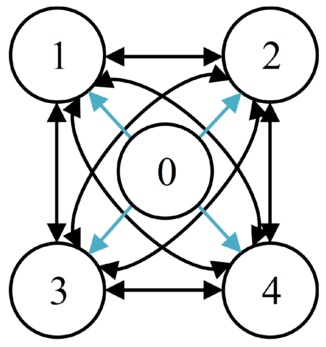
In this section, an MAS consisting of one virtual leader and four wheel-following agents is established as
Figure 1. The black arrows represent the communication links among the four follower agents, while the blue arrows indicate the information transmission from the virtual leader to the follower agents. The virtual leader specifies the ideal yaw rate and sideslip angle generated by a single wheel system at the center of mass. The remaining four wheel agents generate the required torque outputs through the controller.
According to the established topology, the adjacency matrix
, degree matrix
, Laplacian matrix
, and matrix
describing the interaction between the leader and followers are expressed as follows:
During the establishment and control of the MAS, the reference model obtained in Equation (
14) is treated as the virtual leader of the vehicle yaw-stability system. The tracking-error equations of the
ith wheel agent relative to the target yaw rate and sideslip angle are defined as
where
and
denote the tracking errors of the sideslip angle and yaw rate, respectively.
Substituting Equations (
10) and (
14) into Equation (
15) yields the stability tracking-error equations for a single wheel agent as
Conventional DYC controllers usually select either the yaw rate or the sideslip angle as the control variable. In this work, both variables are considered. To facilitate the construction of the MAS-based whole-vehicle yaw dynamics model, the tracking-error system is processed by defining
as the aggregated tracking error, reducing the model to
where
Here, is the weighting coefficient of the sideslip angle, . The disturbance and its derivative are assumed to be bounded.
Considering the interactions among agents, the coordinated tracking error
and its time derivative
are defined in Equation (
18), and the corresponding system states are given in Equation (
19).
Combining Equations (
18) and (
19), the yaw-stability dynamics of a single wheel can be written as the following second-order nonlinear MAS:
Define
,
,
,
. According to Equations (
18) and (
19), the corresponding compact state vectors can be expressed as
According to the lumped-disturbance formulation, the error dynamics can be further summarized as
where
,
,
, and
.
The lumped uncertainty is expressed in matrix form in the MAS. It is assumed to be differentiable, and the disturbance and its derivative are bounded as
Thus, the MAS for yaw-stability control has been established, laying the foundation for the DYC controller design.
3. FOTSM-Based Direct Yaw Moment Controller Design
A FOTSM controller is designed in this section, and its stability is proved to realize the final DYC objective.
3.1. Controller Design
For the
ith wheel-drive agent, this paper proposes a DYC strategy based on FOTSM control. The FOTSM surface for a single agent is designed as
where
and
are positive integers;
and
satisfy
, with
. The sliding surfaces of all agents are extended into compact matrix form, as shown in Equation (
25):
where
,
, and
.
Based on the sliding-mode stability state equation in Equation (
20) and the FOTSM surface in Equation (
24), the control law for the
ith wheel agent is designed as follows:
where
, and
.
The designed FOTSM control law can be extended into the following compact matrix form:
where
.
Thus, the MAS-based FOTSM DYC controller is designed.
3.2. Stability Analysis
The stability of the proposed FOTSM controller is analyzed in this subsection. Substituting the control law in Equation (
27) into the FOTSM surface in Equation (
25) gives
Let
. For the fixed undirected topology adopted in this study,
is symmetric positive semidefinite, and
; so,
is symmetric positive definite. Choose the Lyapunov function as
From Equation (
28) and noting that
and
are constant, the derivative of the sliding variable satisfies
Since
is positive definite,
Thus, the sliding variable reaches
in finite time, with the reaching time satisfying
The above result indicates that the state trajectory of the tracking-error system reaches the ideal sliding surface within finite time. Parameters and are selected such that the polynomial satisfies the Hurwitz condition. Therefore, when the ideal sliding-mode system is established, the state of the aggregated tracking-error system converges from any initial condition to the equilibrium point along the designed FOTSM surface in finite time. For the drive system of a DDEV, the proposed controller enables each agent’s yaw rate and sideslip angle to track their ideal values. Consequently, the whole-vehicle yaw rate and sideslip angle track their references, and DYC is achieved through braking the wheels on one side while driving the wheels on the other side.
4. Experimental Results and Discussion
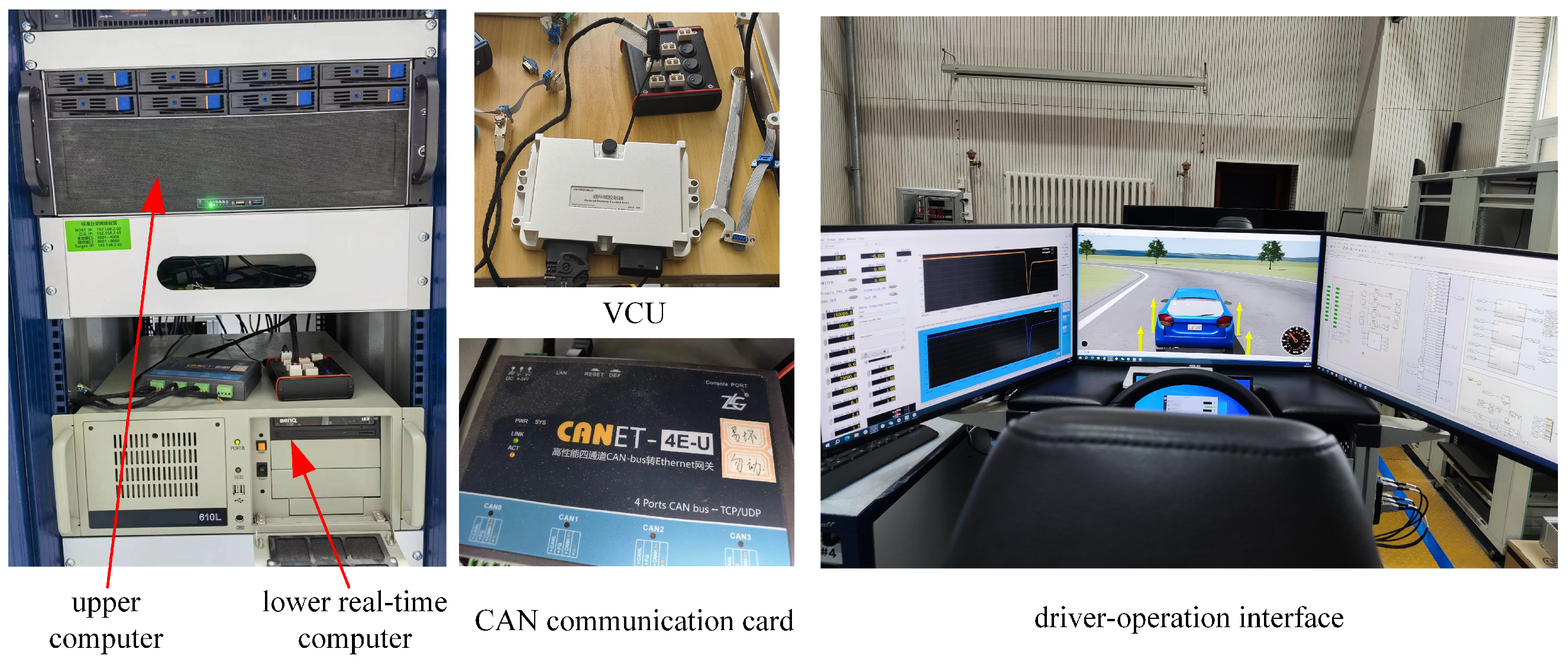
To verify the effectiveness and real-time applicability of the proposed DYC strategy, HIL tests are conducted on a real-time vehicle control platform. The controller is generated from MATLAB/Simulink(R2023b) and deployed to the VCU, which exchanges vehicle-state and wheel-torque commands with the real-time computer through the CAN interface. The platform consists of an upper computer for test management, a real-time computer for vehicle-dynamics execution, the VCU, and the driver-operation interface. The VCU receives steering, acceleration, and braking inputs and outputs the corresponding wheel-driving-torque commands through CAN.
The experimental platform is shown in
Figure 2. The upper computer uses NI VeriStand(2023 Q3) and LabVIEW(2023 Q3) for test management, while the lower real-time computer executes the vehicle dynamics model. The controller developed in MATLAB/Simulink is compiled and deployed to the VCU, which exchanges vehicle states and wheel-torque commands with the real-time computer through the CAN interface, forming a closed-loop HIL environment. The driver-operation interface provides steering, acceleration, and braking inputs.
During the DLC test, the front-wheel steering demand is generated in the closed-loop trajectory-following process according to the instantaneous vehicle response. Therefore, the steering input is not identical for all control cases. When DYC is activated, the additional yaw moment generated by differential wheel torques changes the corrective steering demand required to follow the same target trajectory. The main vehicle parameters used in the HIL experiments are summarized in
Table 1.
The vehicle dynamics model is executed on the real-time computer with a fixed step size of 1 ms. The proposed MAS-FOTSM controller is deployed on the VCU with a control period of 5 ms (200 Hz). Vehicle-state signals and wheel-torque commands are exchanged through the CAN interface within each control cycle. The topology-related matrices and their inverses used in the controller are fixed and are calculated offline. During online execution, the control law mainly involves algebraic operations, matrix–vector operations, and the evaluation of the sliding-mode term, without iterative online optimization. All wheel-torque commands are therefore calculated within the 5 ms control period in the present HIL implementation.
The DLC maneuver is tested at an equivalent vehicle speed of 120 km/h under two cases: without crosswind disturbance and with crosswind disturbance. To evaluate the chattering suppression ability of the proposed FOTSM controller, a conventional MAS-based linear sliding mode controller is implemented on the same HIL platform as a comparative method. The two methods are denoted as MAS-LSM and MAS-FOTSM, and their controller parameters are listed in
Table 2.
4.1. Experimental Results Without Crosswind Disturbance
At an equivalent vehicle speed of 120 km/h and without crosswind disturbance, the experimental results are shown in
Figure 3.
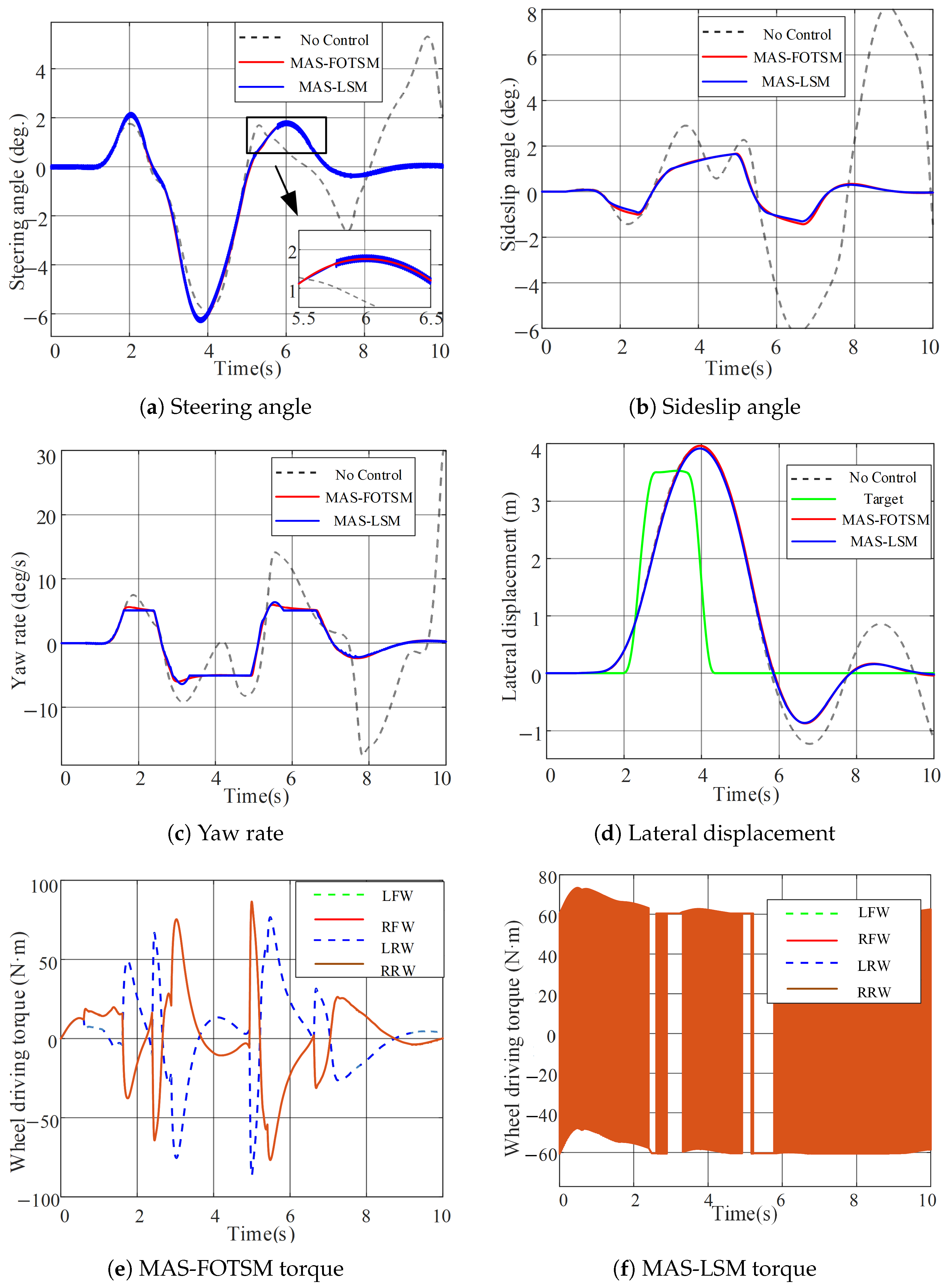
Figure 3a shows that, under the same maneuver, the required front-wheel steering angle is reduced after applying the proposed DYC strategy, indicating improved vehicle stability. Compared with MAS-LSM, MAS-FOTSM markedly attenuates steering-angle chattering.
Figure 3b,c show that, with the established second-order MAS and controller, the sideslip angle and yaw rate are reduced compared with the uncontrolled case and approach their desired values, which also indicates improved driving stability.
Figure 3d shows that the lateral displacement of the vehicle tracks the target trajectory more closely, demonstrating improved driving performance.
Figure 3e,f show that MAS-FOTSM produces a smoother wheel-torque response with less high-frequency switching than MAS-LSM, while maintaining comparable yaw-stability performance.
4.2. Experimental Results Under Crosswind Disturbance
In the crosswind experiment, the wind disturbance is introduced into the vehicle dynamics as an equivalent aerodynamic lateral force. For the lateral crosswind considered in this study, the aerodynamic force is expressed as
where
is the air density,
is the aerodynamic lateral-force coefficient,
is the effective lateral area of the vehicle, and
is the applied crosswind speed. Since the aerodynamic center does not generally coincide with the vehicle center of mass, the crosswind lateral force also generates an additional yaw moment, which is expressed as
where
denotes the longitudinal distance between the aerodynamic center and the vehicle center of mass. Accordingly, the nominal vehicle model in Equation (
1) can be written under crosswind disturbance as
Thus, the crosswind affects both the lateral and yaw motions of the vehicle. Equation (
1) represents the nominal vehicle dynamics used for controller development, while Equations (
35)–(
37) describe the external crosswind disturbance applied in the HIL test. The resulting aerodynamic force and yaw moment are treated as external disturbances within the lumped-disturbance framework of the proposed controller.
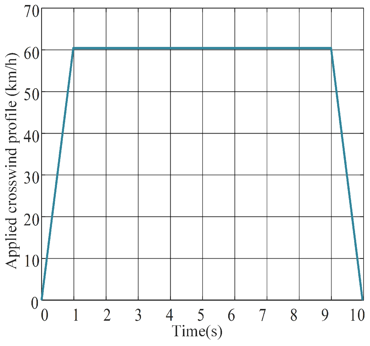
The equivalent vehicle speed is maintained at 120 km/h, and the crosswind speed
varies according to the profile shown in
Figure 4, with a maximum value of 60 km/h. The corresponding lateral aerodynamic force
and yaw moment
are calculated according to Equations (
35) and (
36) and applied to the vehicle dynamics during the HIL test.
The experimental results are shown in
Figure 5.
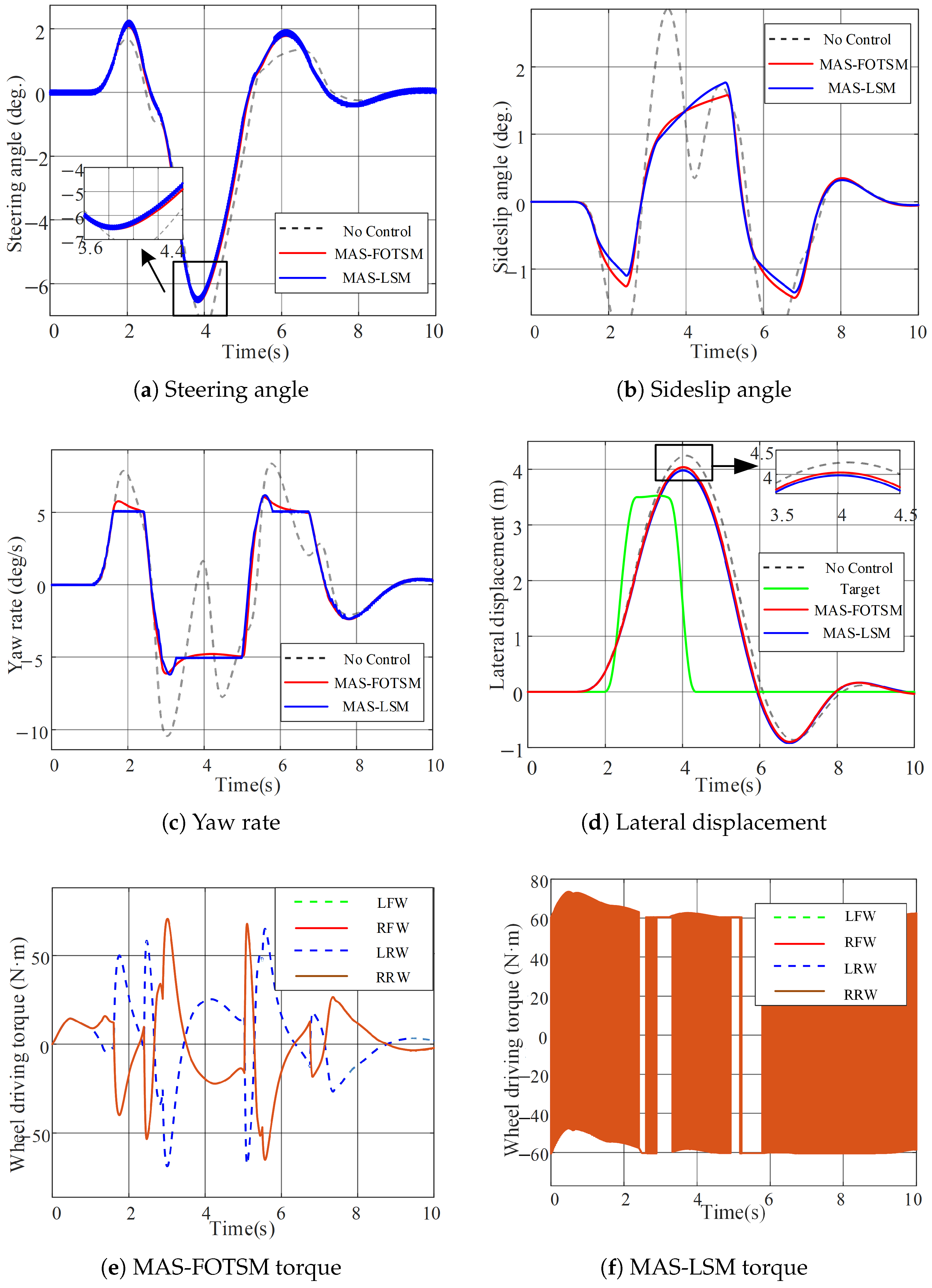
Figure 5a shows that, under crosswind disturbance, the uncontrolled vehicle exhibits loss of control in the front-wheel steering angle near the end of the maneuver, whereas the vehicle remains stable after applying the proposed DYC strategy.
Figure 5b–d show the sideslip angle, yaw rate, and lateral displacement during driving. After the crosswind disturbance is introduced, the uncontrolled vehicle experiences yaw instability, whereas the proposed DYC strategy enables the vehicle to maintain stable motion.
Figure 5e,f show the driving torques under the two control methods. Because of the crosswind disturbance, the driving torques increase for both methods; however, MAS-FOTSM exhibits less high-frequency torque-switching than MAS-LSM while maintaining stable yaw responses under the crosswind disturbance. The applied crosswind profile is shown in
Figure 4.
Table 3 provides a quantitative comparison of the two test conditions. Without crosswind, MAS-FOTSM reduces the peak sideslip angle and peak yaw-rate magnitude by 45.1% and 45.7%, respectively, relative to the uncontrolled vehicle. Under crosswind disturbance, the corresponding reductions exceed 78%. The RMS lateral-displacement tracking errors of MAS-FOTSM and MAS-LSM are 1.30 and 1.26 m without crosswind, and 1.23 and 1.19 m under crosswind, showing comparable trajectory-tracking performance. A clearer difference appears in the torque-variation index
: MAS-FOTSM reduces
from 37.2 to 26.0 N·m without crosswind and from 40.4 to 30.3 N·m under crosswind, corresponding to reductions of 30.1% and 25.0%, respectively. Here,
and
denote the RMS and peak lateral-displacement tracking errors, respectively, while
denotes the standard deviation of the four wheel-torque commands.
5. Discussion
5.1. Interpretation of the Multi-Agent Yaw-Stability Framework
The proposed MAS introduces the four independently actuated wheels directly into the yaw-stability control model. The variables and represent wheel-related contribution states defined by the model decomposition rather than independently measured physical states, and their summation recovers the whole-vehicle sideslip angle and yaw rate. The distributed feature considered in this work refers to the wheel-level agent formulation and the coordination among the four agents through the prescribed topology. In the HIL implementation, the four agent calculations are executed in the VCU, and the resulting wheel-torque commands are transmitted through the CAN network.
5.2. Comparison Between MAS-FOTSM and MAS-LSM
The experimental results show that MAS-FOTSM and MAS-LSM provide similar vehicle-level yaw-stability responses under the tested conditions, while their wheel-torque responses differ noticeably. MAS-LSM exhibits persistent high-frequency torque switching, whereas the torque commands generated by MAS-FOTSM are smoother. In the FOTSM controller, the nonlinear terminal terms modify the error dynamics, and the switching term enters the control input through integration; so, the discontinuous sign function is not applied directly to the wheel-torque command. Therefore, the advantage of MAS-FOTSM observed in the present tests is mainly the reduction in high-frequency torque activity while maintaining comparable yaw-stability performance, rather than a uniformly smaller peak torque.
5.3. Limitations and Future Work
The modeling and stability analysis in this study are established within a specific range of applicability. The tire lateral force is approximated by a linear model under small-slip-angle conditions, while the stability analysis assumes bounded lumped disturbances and their derivatives. When the vehicle approaches the handling limit, large tire slip angles, tire-force saturation, or disturbances exceeding the assumed bounds may reduce the model accuracy and affect the tracking and stability performance. Therefore, the present conclusions should be interpreted within the tested operating range. The current HIL validation is also limited to a 120 km/h DLC maneuver with one crosswind profile, and MAS-LSM is the only active-control baseline. Future work will consider nonlinear tire characteristics, tire-force saturation, different vehicle speeds, road-friction levels, and more severe disturbance conditions. Comparisons with centralized FOTSM, LQR, and MPC, together with repeated HIL tests and vehicle-level experiments, will also be conducted to further evaluate the robustness and practical applicability of the proposed method.
6. Conclusions
This paper investigated an MAS-based DYC strategy for DDEVs. First, a reduced-order yaw-dynamics model of a DDEV was derived based on the vector superposition principle, and a yaw-stability-oriented MAS was established. Then, an FOTSM controller was proposed for the developed MAS, realizing DYC with finite-time convergence and strong disturbance rejection. Finally, HIL experimental tests were conducted under DLC maneuvers with and without crosswind disturbance to verify the effectiveness and superiority of the proposed controller. The experimental results show that the proposed MAS-FOTSM method improves yaw stability, enhances lateral trajectory tracking, and reduces driving-torque chattering compared with the conventional MAS-LSM method. Under crosswind disturbance, the proposed strategy maintains vehicle stability and avoids loss of control, demonstrating its potential for engineering application in DDEV chassis control.
Author Contributions
Conceptualization, Q.G. and L.J.; methodology, M.Z. and G.G.; software, M.Z.; validation, M.Z., N.Z. and F.Q.; formal analysis, M.Z. and G.G.; investigation, M.Z. and Z.W.; resources, Q.G. and L.J.; data curation, M.Z.; writing—original draft preparation, M.Z.; writing—review and editing, Q.G., L.J. and N.Z.; visualization, M.Z. and F.Q.; supervision, L.J. and Q.G.; project administration, Q.G. and L.J. All authors have read and agreed to the published version of the manuscript.
Funding
This research was supported in part by the Natural Science Foundation for Excellent Young Scholars of Heilongjiang Province under Grant YQ2024E043, the National Natural Science Foundation of China, under Grant 52477041, and the Fundamental Research Foundation for Universities of Heilongjiang Province (2024-KYYWF-0929).
Institutional Review Board Statement
Not applicable.
Informed Consent Statement
Not applicable.
Data Availability Statement
All relevant data are included in this paper.
Conflicts of Interest
The authors declare no conflicts of interest.
Abbreviations
The following abbreviations are used in this manuscript:
| DDEV | Distributed-drive electric vehicle |
| DYC | Direct yaw moment control |
| MAS | Multi-agent system |
| FOTSM | Full-order terminal sliding mode |
| LSM | Linear sliding mode |
| DLC | Double-lane change |
| SMC | Sliding mode control |
| MPC | Model predictive control |
| LQR | Linear quadratic regulator |
| PID | Proportional-integral-derivative |
References
- Wang, H.; Han, J.; Zhang, H. Lateral Stability Analysis of 4WID Electric Vehicle Based on Sliding Mode Control and Optimal Distribution Torque Strategy. Actuators 2022, 11, 244. [Google Scholar] [CrossRef] [Scilit]
- Zhai, L.; Sun, T.; Wang, J. Electronic Stability Control Based on Motor Driving and Braking Torque Distribution for a Four In-Wheel Motor Drive Electric Vehicle. IEEE Trans. Veh. Technol. 2016, 65, 4726–4739. [Google Scholar] [CrossRef] [Scilit]
- Nam, K.; Fujimoto, H.; Hori, Y. Lateral Stability Control of In-Wheel-Motor-Driven Electric Vehicles Based on Sideslip Angle Estimation Using Lateral Tire Force Sensors. IEEE Trans. Veh. Technol. 2012, 61, 1972–1985. [Google Scholar] [CrossRef] [Scilit]
- Liu, H.; Liu, C.; Han, L.; Xiang, C. Handling and Stability Integrated Control of AFS and DYC for Distributed Drive Electric Vehicles Based on Risk Assessment and Prediction. IEEE Trans. Intell. Transp. Syst. 2022, 23, 23148–23163. [Google Scholar] [CrossRef] [Scilit]
- Zhang, H.; Wang, S.; Zhao, X.; Zheng, Z. Path Tracking and Handling Stability Coordinated Control of 4WS and DYC for Distributed In-Wheel Motor Drive Electric Vehicle Under Extreme Conditions. IEEE Trans. Veh. Technol. 2024, 73, 18402–18417. [Google Scholar] [CrossRef] [Scilit]
- Guo, N.; Lenzo, B.; Zhang, X.; Zou, Y.; Zhai, R.; Zhang, T. A Real-Time Nonlinear Model Predictive Controller for Yaw Motion Optimization of Distributed Drive Electric Vehicles. IEEE Trans. Veh. Technol. 2020, 69, 4935–4946. [Google Scholar] [CrossRef] [Scilit]
- Liu, C.; Liu, H.; Han, L.; Wang, W.; Guo, C. Multi-Level Coordinated Yaw Stability Control Based on Sliding Mode Predictive Control for Distributed Drive Electric Vehicles Under Extreme Conditions. IEEE Trans. Veh. Technol. 2023, 72, 280–296. [Google Scholar] [CrossRef] [Scilit]
- Falcone, P.; Borrelli, F.; Asgari, J.; Tseng, H.E.; Hrovat, D. Predictive Active Steering Control for Autonomous Vehicle Systems. IEEE Trans. Control Syst. Technol. 2007, 15, 566–580. [Google Scholar] [CrossRef] [Scilit]
- He, J.; Crolla, D.A.; Levesley, M.C.; Manning, W.J. Integrated Active Steering and Variable Torque Distribution Control for Improving Vehicle Handling and Stability; SAE Technical Paper; SAE International: Warrendale, PA, USA, 2004; 2004-01-1071. [Google Scholar] [CrossRef] [Scilit]
- Subroto, R.K.; Wang, C.Z.; Lian, K.L. Four-Wheel Independent Drive Electric Vehicle Stability Control Using Novel Adaptive Sliding Mode Control. IEEE Trans. Ind. Appl. 2020, 56, 5995–6006. [Google Scholar] [CrossRef] [Scilit]
- Zhang, Y.; Ma, J.; Zhou, Y. Adaptive Nonsingular Fast Terminal Sliding Mode-Based Direct Yaw Moment Control for DDEV under Emergency Conditions. Actuators 2024, 13, 170. [Google Scholar] [CrossRef] [Scilit]
- Feng, Y.; Yu, X.; Man, Z. Non-Singular Terminal Sliding Mode Control of Rigid Manipulators. Automatica 2002, 38, 2159–2167. [Google Scholar] [CrossRef] [Scilit]
- Xu, Z.; Ge, S.S.; Liu, W.; Yi, G.; Xie, Z.; Li, K. Intermittently Dynamic Fuzzy Learning-Based Tracking Control of Amplitude Signals for Vibratory Gyroscopes with Composite Identification. IEEE Trans. Instrum. Meas. 2025, 74, 9518508. [Google Scholar] [CrossRef] [Scilit]
- Mei, J.; Jian, H.; Li, Y.; Wang, W.; Lin, D. Deep neural networks-based output-dependent intermittent control for a class of uncertain nonlinear systems. Chaos Solitons Fractals 2024, 185, 114999. [Google Scholar] [CrossRef] [Scilit]
- Mei, J.; Ye, R.; Xiang, Z.; Hu, J.; Wang, W. A Direct Data-Driven Intermittent Control and Learning via Lyapunov-Guided Attraction Region Estimation with Neural Feedback Loop Design. IEEE Trans. Autom. Sci. Eng. 2026, 23, 6504–6519. [Google Scholar] [CrossRef] [Scilit]
- Olfati-Saber, R.; Fax, J.A.; Murray, R.M. Consensus and Cooperation in Networked Multi-Agent Systems. Proc. IEEE 2007, 95, 215–233. [Google Scholar] [CrossRef] [Scilit]
- Ren, W.; Beard, R.W.; Atkins, E.M. Information Consensus in Multivehicle Cooperative Control. IEEE Control Syst. Mag. 2007, 27, 71–82. [Google Scholar] [CrossRef] [Scilit]
- Cao, Y.; Yu, W.; Ren, W.; Chen, G. An Overview of Recent Progress in the Study of Distributed Multi-Agent Coordination. IEEE Trans. Ind. Inform. 2013, 9, 427–438. [Google Scholar] [CrossRef] [Scilit]
- Liang, J.; Lu, Y.; Yin, G.; Fang, Z.; Zhuang, W.; Ren, Y.; Xu, L.; Li, Y. A Distributed Integrated Control Architecture of AFS and DYC Based on MAS for Distributed Drive Electric Vehicles. IEEE Trans. Veh. Technol. 2021, 70, 5565–5577. [Google Scholar] [CrossRef] [Scilit]
- Wang, L.; Shu, Q.; Zhou, D.; Ti, Y. Extenics Coordinated Torque Distribution Control for Distributed Drive Electric Vehicles Considering Stability and Energy Efficiency. Actuators 2026, 15, 3. [Google Scholar] [CrossRef] [Scilit]
- Hang, P.; Xia, X.; Chen, X. Handling Stability Advancement with 4WS and DYC Coordinated Control: A Gain-Scheduled Robust Control Approach. IEEE Trans. Veh. Technol. 2021, 70, 3164–3174. [Google Scholar] [CrossRef] [Scilit]
- Cao, W.; Liu, C.; Liu, Z.; Wei, Z. Integrated LKA and DYC Control of Four-Wheel-Independent-Drive Electric Vehicles with a Central-Zonal Electronic and Electrical Architecture. IEEE Trans. Veh. Technol. 2024, 73, 14592–14603. [Google Scholar] [CrossRef] [Scilit]
- Wang, S.; Yu, H.; Yuan, S.; Li, S.E.; Ning, Z. Velocity Planning for Multi-Vehicle Systems via Distributed Optimization. In Proceedings of the 2023 IEEE 26th International Conference on Intelligent Transportation Systems (ITSC), Bilbao, Spain, 24–28 September 2023; pp. 4491–4497. [Google Scholar] [CrossRef] [Scilit]
- Lian, Y.; Chen, G.; Liu, P. Study of Yaw Moment Control Strategy of Four Wheel Independent Drive Electric Vehicle. Automot. Innov. 2025, 8, 157–168. [Google Scholar] [CrossRef] [Scilit]
- Zhang, L.; Sun, L.; Ding, X.; Wang, Z. Cooperative Trajectory Tracking and Stability Control with Improved Stability Criterion for Intelligent Four-Wheel-Independent-Drive Electric Vehicles. Automot. Innov. 2025, 8, 187–204. [Google Scholar] [CrossRef] [Scilit]
| Disclaimer/Publisher’s Note: The statements, opinions and data contained in all publications are solely those of the individual author(s) and contributor(s) and not of MDPI and/or the editor(s). MDPI and/or the editor(s) disclaim responsibility for any injury to people or property resulting from any ideas, methods, instructions or products referred to in the content. |



 ,
,