Article

Comparative Analysis of Y- and Delta-Connected Windings in Line-Start Permanent Magnet Motors with Different Rotor Configurations


1
Department of Next Generation Energy System Convergence, Gachon University, Seongnam 13120, Republic of Korea
2
Department of Electrical Control Engineering, Cheongju University, Cheongju 28503, Republic of Korea
3
A School of Advanced Materials and Electrical Engineering, Gyeongkuk National University, Andong 36729, Republic of Korea
*
Author to whom correspondence should be addressed.
Actuators 2026, 15(9), 462; https://doi.org/10.3390/act15090462 (registering DOI)
Submission received: 6 August 2026 / Revised: 20 August 2026 / Accepted: 26 August 2026 / Published: 28 August 2026
(This article belongs to the Special Issue Advanced Design and Control of Electrical Machines)

Abstract

A line-start permanent-magnet motor (LSPM) combines the direct-on-line starting capability of a squirrel-cage induction motor (IM) with permanent-magnet-assisted synchronous operation. Previous studies on LSPM winding connections have mainly focused on load-dependent efficiency and the power factor, while their effects on harmonics, torque ripple, and synchronization across different rotor configurations remain unclear. This study compares Y- and delta-connected windings in two 5.5 kW, four-pole LSPM models using transient finite-element analysis. Current and voltage harmonics, losses, efficiency, torque ripple, and synchronization response were evaluated. The Y-connected cases exhibited lower current harmonic distortion and stator copper loss, whereas the delta-connected cases reduced torque ripple and maximum speed overshoot but required slightly longer settling times. For LSPM-B, the Y connection achieved the highest efficiency of 92.92% with a stator copper loss of 137.81 W, while the delta connection reduced the torque ripple ratio from 43.8% to 39.5%. These results demonstrate that winding-connection effects depend on the rotor magnetic circuit and cage-assisted starting characteristics, requiring a trade-off among efficiency, harmonic loss, torque ripple, and synchronization response.

1. Introduction

Three-phase induction motors are widely used in industrial applications because of their robust structure, low cost, and direct-on-line starting capability. However, their efficiency and power factor are limited by the magnetizing current required to establish the air-gap flux and by rotor copper loss. Therefore, line-start permanent magnet motors (LSPMs) have been investigated as high-efficiency alternatives to conventional induction motors [1,2,3]. LSPMs combine permanent magnets and a squirrel-cage rotor, enabling asynchronous starting through the cage and high-efficiency synchronous operation after pull-in [4,5].
Although an LSPM operates similarly to a conventional PMSM after synchronization, it additionally includes a squirrel-cage winding for direct-on-line starting. Therefore, its starting and synchronization characteristics are determined by the interaction among cage induction torque, permanent-magnet braking torque, and reluctance torque. Accordingly, this study focuses on the effects of Y and delta winding connections on both the steady-state and synchronization characteristics of LSPMs with different rotor configurations. Previous studies have mainly focused on improving the rotor configuration and synchronization characteristics of LSPMs. Rotor magnetic materials, magnet arrangement, cage-bar design, magnetizing inductance, and asynchronous torque have been investigated to improve starting torque, pull-in capability, and steady-state performance [6,7]. In addition, several rotor optimization studies have been conducted considering the trade-off between starting performance and synchronous efficiency [8,9,10,11,12,13].
Stator winding design also affects the electromagnetic performance of LSPMs. The number of winding turns influences the induced voltage, stator current, power factor, copper loss, and iron loss [14]. Ferreira et al. [15] investigated winding connection-mode management to improve load-dependent steady-state efficiency and power factor. Although their study included LSPMs of several power ratings, rotor geometry was not treated as a controlled design variable, and current and voltage harmonic distortion, torque ripple, and direct-on-line synchronization were not systematically compared under Y- and delta-connected conditions. Hybrid salient-rotor structures incorporating slotted solid-steel regions and cage bars have also been investigated to improve starting and synchronization performance while reducing air-gap flux-density harmonics and motor losses [16]. Therefore, the coupled influence of the stator winding connection and rotor magnetic circuit remains unresolved. This gap is important because the closed delta winding provides a path for triplen zero-sequence circulating currents, whereas the flux-barrier and cage geometries modify harmonic-flux paths and the torque balance during pull-in.
Although LSPMs and Y–delta winding connections are established technologies, their combined electromagnetic effects do not necessarily remain independent of the rotor configuration. Therefore, the contribution of this study does not originate from proposing a new winding connection or rotor topology, but from quantitatively identifying how the effects of the winding connection depend on the rotor magnetic circuit. For this purpose, two 5.5 kW, four-pole LSPM models with different magnetic-flux paths and cage characteristics are investigated under Y- and delta-connected conditions. Transient finite-element analysis is performed to evaluate current and voltage harmonics, stator copper loss, iron loss, efficiency, torque ripple, maximum speed overshoot, and settling time. Analytical relationships for the zero-sequence harmonic-current paths, stator magnetomotive force, harmonic copper loss, and torque components are introduced to interpret the underlying electromagnetic mechanisms. Furthermore, the connection-induced performance change and interaction contrast are defined to quantify the differences between the Y-to-delta performance changes in LSPM-A and LSPM-B. This interaction-based analysis distinguishes the connection effects common to both rotor models from those dependent on the rotor magnetic circuit. Accordingly, the results provide case-specific design considerations for selecting an appropriate winding connection while accounting for the trade-offs among efficiency, harmonic loss, torque ripple, and synchronization response.

2. Motor Configuration and Analysis Method

2.1. Conventional Induction Motor and LSPM-A Design

Figure 1 compares the rotor configurations of the conventional induction motor (conventional IM) and the reference line-start permanent magnet motor, hereafter designated as LSPM-A. As shown in Figure 1a, the conventional IM employs a conventional double-cage rotor structure. In contrast, the LSPM-A shown in Figure 1b retains the rotor bars required for direct-on-line starting and incorporates permanent magnets to provide the air-gap flux during synchronous operation. Because a portion of the air-gap flux is supplied by the permanent magnets during steady-state operation, the stator magnetizing current requirement can be reduced. In addition, the rotor-bar current is significantly reduced after synchronization, resulting in lower rotor copper loss. Consequently, the LSPM-A can achieve improved steady-state efficiency compared with the conventional IM.
Table 1 compares the electromagnetic performance of the conventional IM and the LSPM-A under rated operating conditions. The LSPM-A achieved an operating speed of 1780 rpm and an output torque of 29.44 N·m, maintaining a rated operating performance comparable to that of the conventional IM. In contrast, the RMS phase-winding current was reduced from 11.5 A to 9.08 A, corresponding to a reduction of approximately 21.0%. While the output power increased from 5449 W to 5524 W, the input power decreased from 6100 W to 5965 W. As a result, the efficiency increased from 89.33% to 92.60%, corresponding to an improvement of approximately 3.27 percentage points.

2.2. Rotor Configurations of LSPM-A and LSPM-B

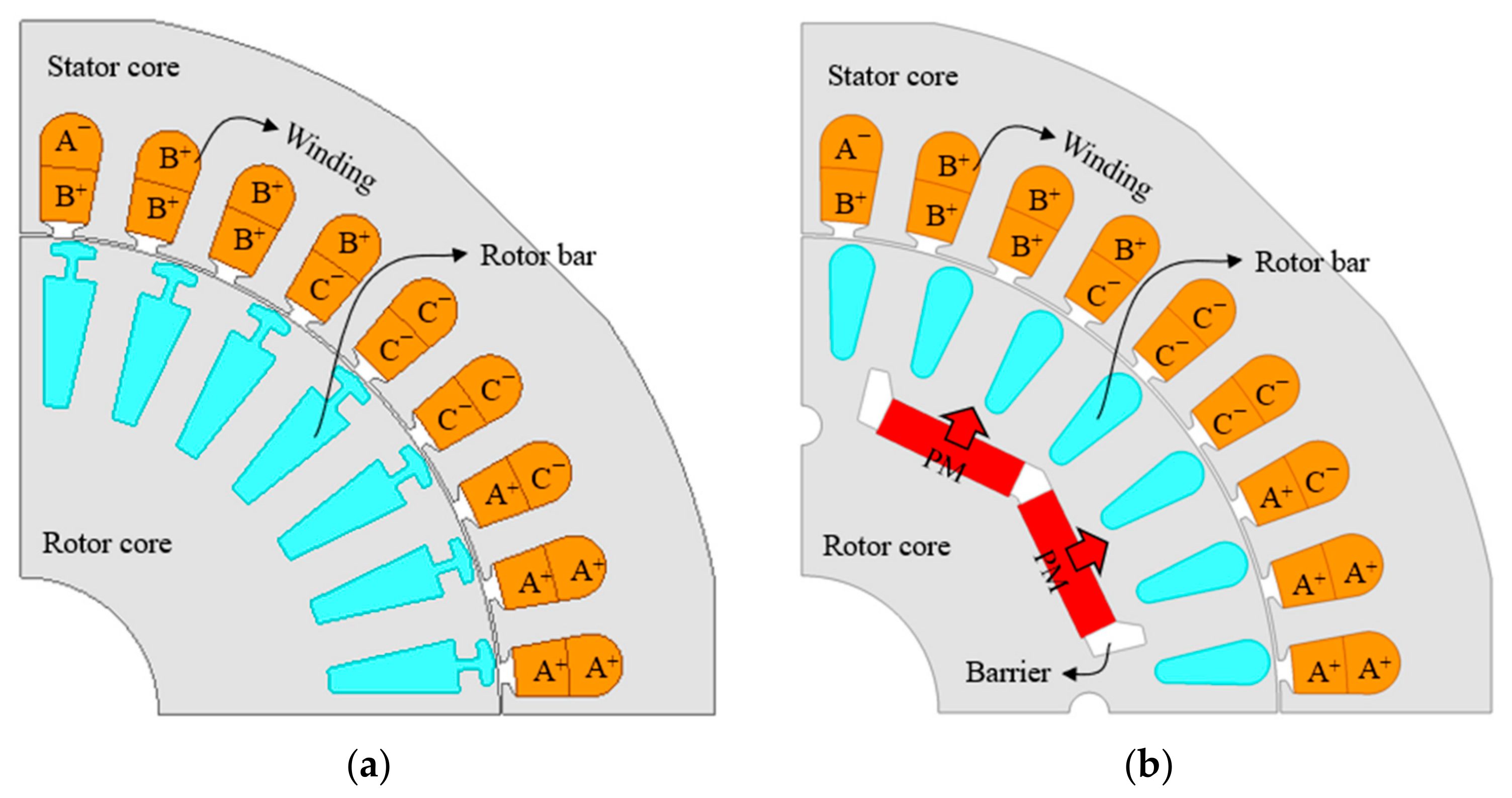
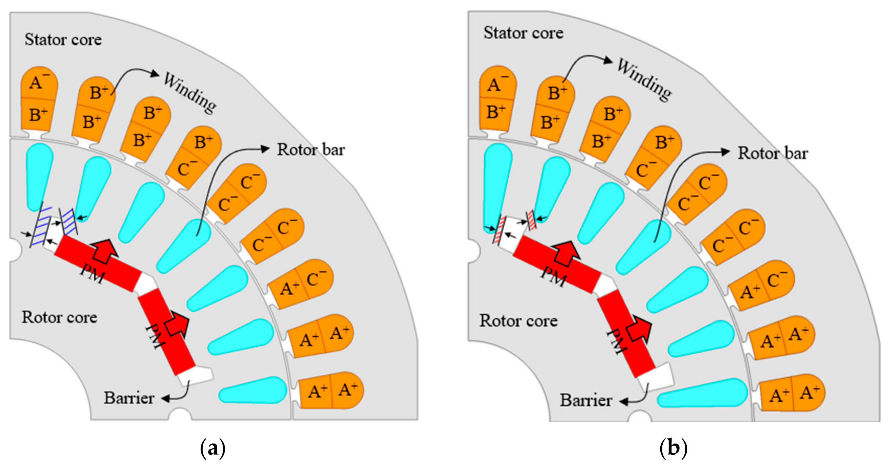
Whereas Figure 1 compares two different machine types, Figure 2 provides an internal rotor-geometry comparison within the investigated LSPM family. The rotor shown in Figure 2a is the reference LSPM-A introduced in Section 2.1, whereas Figure 2b shows the modified LSPM-B. Both models share the same stator structure, basic permanent-magnet arrangement, and rotor-cage configuration, but differ in the local geometry around the permanent-magnet ends, flux barriers, and adjacent rotor bars.
In the LSPM-B, the spacing between the flux barrier and the rotor bar was adjusted to reduce internal leakage flux. Specifically, the thickness of the flux barrier was increased, and the length of the rotor bar adjacent to the barrier was extended to reduce the distance between the two structures. This modification was intended to suppress the leakage flux path that can be formed from the permanent-magnet region toward the rotor core and rotor bars. The two models have the same stator structure, basic permanent-magnet arrangement, and rotor-bar configuration; however, they differ in the geometry around the permanent-magnet ends and flux-barrier regions. These geometric differences affect the rotor magnetic circuit, including the effective air-gap flux path, local magnetic saturation distribution, and asynchronous torque characteristics associated with the rotor bars. Therefore, the two rotor models can exhibit different electromagnetic responses even under identical stator winding connection conditions.
The purpose of this study is not to revisit the rotor optimization process or to determine the superiority of a specific rotor geometry. Instead, the LSPM-A and LSPM-B models are used as representative rotor configurations with different magnetic circuits to investigate the influence of Y and delta winding connections on the electromagnetic performance of LSPMs. Therefore, the results of this study should be interpreted as a case-based comparison of two representative rotor geometries, rather than as continuous sensitivity trends with respect to variations in air-gap length, permanent-magnet thickness, or rotor-bar cross-sectional area. Accordingly, the following analysis focuses on the differences in current and voltage harmonics, losses, efficiency, torque ripple, and synchronization characteristics according to the stator winding connection for both rotor models.

2.3. Stator Winding Connection Conditions

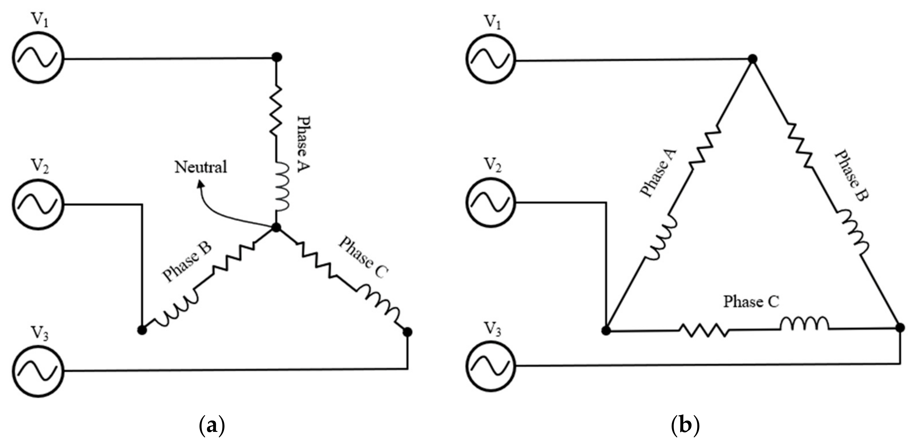
Figure 3 illustrates the stator winding connection configurations considered in this study. Figure 3a shows the Y-connected winding configuration, in which one terminal of each three-phase winding is connected to a common neutral point. Under the Y-connected condition, each phase winding is driven by the corresponding phase-to-neutral voltage, and the phase current and magnetic flux distribution are determined by the phase voltage applied to each winding and the common neutral-point condition. Figure 3b shows the delta-connected winding configuration, in which the three phase windings are connected in a closed loop. In the delta connection, each phase winding is connected between two line terminals and is subjected to the line-to-line voltage. Therefore, even under the same line-to-line voltage condition, the voltage applied to each winding and the current paths differ from those of the Y connection. In particular, the closed-loop structure of the delta connection can affect harmonic current components and the electromagnetic response of the motor. To evaluate the influence of the stator winding connection, the Y- and delta-connected conditions were applied to both the LSPM-A and LSPM-B models under identical supply-frequency, load, and rotor operating conditions. Since the phase-winding voltage and current paths differ between the two connections under the same line-to-line voltage condition, the subsequent results are interpreted as connection-dependent operating characteristics rather than as purely isolated connection effects.

2.4. Theoretical Analysis of Winding-Connection Effects

Under balanced fundamental-frequency conditions, the phase voltage and current relationships differ between the Y and delta connections. For the Y connection, the phase voltage and line current are expressed as
V p h , Y = V L 3 ,   I L , Y = I p h , Y
For the delta connection, the corresponding relationships are
V p h , = V L ,   I L , = 3 I p h ,
where V L , V p h , I L , and I p h are the line voltage, phase-winding voltage, line current, and phase-winding current, respectively. Equation (2) is valid for the balanced fundamental component. When harmonic currents are included, the delta line current is determined by the difference between the currents flowing through two adjacent winding branches. In this study, the reported current is defined as the RMS phase-winding current flowing through each winding branch. Therefore, it is equal to the terminal line current in the Y-connected cases but differs from the line current in the delta-connected cases. Under balanced three-phase conditions, the h th-order phase electromotive-force phasors can be expressed as follows [17]:
E a , h = E h ,             E b , h = E h e j 2 π h / 3 ,             E c , h = E h e j 2 π h / 3
The corresponding zero-sequence electromotive force is
E 0 , h = E a , h + E b , h + E c , h 3 = { E h ,           h = 3 k , 0 ,               h 3 k
where h is the harmonic order, k is a positive integer, j is the imaginary unit, and E a , h , E b , h , and E c , h are the h th-order electromotive-force phasors of phases a, b, and c, respectively. Therefore, both the 3rd- and 15th-order components satisfy the zero-sequence condition because their harmonic orders are integer multiples of three. In an ungrounded Y connection, the zero-sequence current cannot flow because a closed current path does not exist. In contrast, the delta connection provides a closed path through the three phase-winding branches. The corresponding zero-sequence currents can be expressed as [17]
I 0 , h Y = 0 ,                           I c i r c , h = E 0 ,   h R s + j h ω e L 0 ,   h ,           h = 3 k
where I 0 , h Y is the zero-sequence current under the Y connection, I c i r c , h is the circulating current in each delta-connected phase-winding branch, R s is the phase resistance, L 0 , h is the effective zero-sequence inductance at the h th harmonic, and ω e is the fundamental electrical angular frequency. A pure zero-sequence component is canceled in the delta terminal line current because the currents in two adjacent winding branches are subtracted. However, it remains as a circulating current within the individual phase-winding branches [17]. Therefore, the 3rd- and 15th-order components can be considerably larger in the delta phase-winding current evaluated in this study, even when they are suppressed in the terminal line current. The magnetomotive-force component produced by the zero-sequence current can be represented as
F v , h = N k w , v I c i r c , h Δ ( 1 + e j 2 π v / 3 + e j 2 π v / 3 )
where F v , h is the magnetomotive-force component with spatial order v and time-harmonic order h , N is the number of series turns per phase, and k w , v is the winding factor of the v th spatial harmonic. The term in parentheses becomes three when v = 3 m and zero for the other spatial orders, where m is a positive integer. Consequently, the zero-sequence current does not produce a fundamental rotating magnetomotive force. Instead, it produces triplen spatial harmonics and a pulsating air-gap flux. Previous research has shown that such a pulsating flux can interact with the conducting parts of the rotor and produce additional electromagnetic losses [17]. The coupling between the rotor geometry and zero-sequence harmonic electromotive force can be described using the following simplified harmonic magnetic-circuit relationships:
E 0 , h = j h ω e N k w , h Φ 0 , h , λ l , h = | Φ l , h | | Φ g ,   h | R g ,   h R l , h
where Φ 0 , h , Φ l , h , and Φ g , h are the zero-sequence harmonic flux, rotor-leakage harmonic flux, and air-gap harmonic flux, respectively. In addition, k w , h is the winding factor associated with the h th harmonic, λ l , h is the harmonic leakage-flux ratio, and R g , h and R l , h are the effective magnetic reluctances of the air-gap and rotor-leakage paths, respectively. Reluctance-network analysis of LSPMs has demonstrated that the flux-bridge geometry and local magnetic saturation affect the permanent-magnet flux linkage and induced electromotive force. The impedance of the rotor cage corresponding to the th harmonic can be approximated as [18,19]
Z r , h = R r , h + j ω r , h L r , h , R r , h ρ r l r A b a r ,   e f f ,   h
where Z r , h , R r , h , and L r , h are the effective harmonic impedance, resistance, and inductance of the rotor cage, respectively. In addition, ω r , h is the angular frequency of the harmonic field observed from the rotor, ρ r is the electrical resistivity of the rotor-bar material, l r is the effective rotor-bar current-path length, and A b a r , e f f , h is the effective rotor-bar cross-sectional area considering the frequency-dependent current distribution. Previous multidamping-circuit and analytical damping-bar models have demonstrated that the rotor-bar dimensions and arrangement affect the rotor resistance, leakage inductance, mutual inductance, and harmonic response of LSPMs [18,19]. Increasing the flux-barrier thickness increases R l , h and restricts the internal leakage-flux path. However, the redirected flux may become concentrated in the narrow iron regions between adjacent rotor bars. The resulting local saturation reduces the differential permeability and increases the distortion of the magnetic-flux waveform. Simultaneously, changes in the rotor-bar geometry modify R r , h , L r , h , and the harmonic shielding effect of the cage [18,19]. Therefore, the rotor configuration affects both the zero-sequence harmonic electromotive force in the numerator and the effective zero-sequence impedance in the denominator of Equation (5). The additional copper loss associated with the delta circulating currents is expressed as
P c u , c i r c = 3 R s h = 3 k | I c i r c ,   h | 2
Under the constant phase-resistance assumption used in this study, the ratio of harmonic copper loss to total copper loss can be obtained from the current THD as
γ c u , h a r m = P c u ,   h a r m P c u = T H D I 2 1 + T H D I 2
where P c u , c i r c is the copper loss caused by the delta zero-sequence circulating currents, P c u , h a r m is the copper loss caused by all harmonic-current components, P c u is the total copper loss, γ c u , h a r m is the harmonic copper-loss ratio, and T H D I is the current total harmonic distortion expressed in per-unit form. Thus, the larger 3rd- and 15th-order circulating currents in the delta-connected cases increase the harmonic contribution to the phase-winding copper loss, although their resultant pulsating flux can modify the torque harmonics through phase-dependent interactions with the rotor field [17].
These circulating harmonic currents modify the stator magnetomotive-force distribution and its interaction with the rotor magnetic field, thereby affecting the electromagnetic torque and torque-ripple characteristics. In an LSPM, the influence of the winding connection extends to the direct-on-line starting and synchronization processes because the motor contains both permanent magnets and a squirrel-cage winding. The starting dynamics can be described by the mechanical equation [6]
J d ω m d t = T c a g e + T P M + T r e l T L B ω m
where J , ω m , T c a g e , T P M , T r e l , T L , and B ω m represent the total moment of inertia, mechanical angular speed, cage induction torque, permanent-magnet torque, reluctance torque, load torque, and viscous friction torque, respectively. To clarify the coupling among these torque components, the fundamental electromagnetic torque can be decomposed in the rotor d-q reference frame as [6,18,19]
T e = T c a g e + T P M + T r e l , T P M = 3 2 p ψ P M i q , T r e l = 3 2 p ( L d L q ) i d i q , T c a g e = 3 2 p ( M d i r d i q M q i r q i d )
where T e , p , and ψ P M denote the total electromagnetic torque, number of pole pairs, and permanent-magnet flux linkage, respectively; i d and i q are the d - and q -axis stator currents; L d and L q are the corresponding stator inductances; i r d and i r q are the equivalent d - and q -axis rotor-cage currents; and M d and M q are the mutual inductances between the stator winding and rotor cage. During asynchronous starting, T c a g e provides the principal positive accelerating torque, whereas T P M contains braking and oscillating components. T r e l also varies periodically because of rotor saliency. As the slip approaches zero, the cage-current component decreases, while the permanent-magnet and reluctance torques establish synchronous operation. The winding connection changes the stator and rotor-cage currents, whereas the rotor geometry affects the inductance, rotor-bar impedance, and coupling between the torque components. Therefore, the torque balance varies according to both the winding connection and rotor configuration. Equation (12) is used for mechanism-based interpretation, whereas the nonlinear transient FEA provides the total electromagnetic torque.

2.5. Finite-Element Analysis Method

In this study, two-dimensional transient finite-element analysis (FEA) was performed using the commercial electromagnetic simulation software ANSYS Maxwell 2025 R2. The 2D FEA calculates the time-varying magnetic-field distribution and electromagnetic characteristics in the x–y cross-sectional plane of the motor, assuming a uniform axial geometry. The governing equation used in the analysis is expressed as
· ( ν A ) σ A t = ν μ 0 ( M x y M y x )
where A is the axial component of the magnetic vector potential, while ν and σ are the material reluctivity and electrical conductivity, μ 0 is the permeability of free space, and M x and M y are the x- and y-components of the magnetization vector inside the permanent magnet. Since the reluctivity is modeled as a nonlinear function of magnetic flux density, the formulation inherently accounts for magnetic saturation in the iron core [20]. The iron loss was calculated using the Electrical Steel core-loss model implemented in ANSYS Maxwell 2025 R2. This model is based on Bertotti’s three-term loss-separation method. The total iron-loss density is expressed as
P F e = P h + P c + P e = K h f B m α + K c ( f B m ) 2 + K e ( f B m ) 1.5
where P F e , P h , P c , and P e represent the iron, hysteresis, classical eddy-current, and excess-loss components, respectively. K h , K c , and K e denote the hysteresis, classical eddy-current, and excess-loss coefficients, respectively; α is the hysteresis exponent; f is the magnetic excitation frequency; and B m is the peak magnetic flux density. These coefficients were obtained from the material properties defined for 50PN470. During the transient analysis, Maxwell evaluated the loss components element by element using the local time-varying flux-density waveform and integrated them over the laminated stator and rotor cores. The reported iron loss represents the sum of these loss components. Identical material coefficients and core-loss settings were applied to all investigated models.
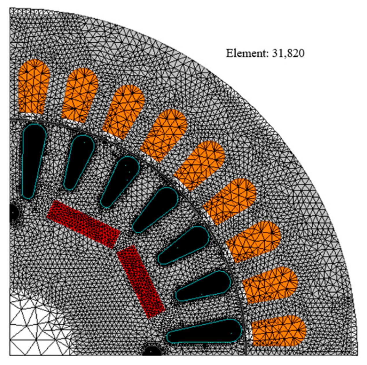
Figure 4 shows the finite-element mesh applied to the investigated model. The analysis model consisted of approximately 31,820 elements, and relatively fine meshes were applied to regions with large magnetic-field variations, including the air gap, permanent-magnet region, rotor bars, and stator tooth tips. To investigate the transient starting behavior and the steady-state characteristics after synchronization, transient FEA was performed for 30 electrical cycles. Each analysis required approximately 1 h 20 min. The same mesh density and time-domain conditions were applied to all cases to ensure a consistent comparison of the electromagnetic performance according to the rotor configuration and stator winding connection. In the starting analysis, the LSPM was directly connected to a balanced three-phase 60 Hz supply without an inverter or closed-loop speed/current controller. Identical supply voltage, rated load torque of approximately 29.4 N·m, mechanical inertia, and initial conditions were applied to all cases. Therefore, the connection-dependent trends presented in this study are specific to the rated operating condition and should not be directly generalized to the entire load range. Changes in load torque may affect the stator current, load angle, magnetic saturation, harmonic losses, and torque balance during synchronization. Accordingly, the relative performance of the Y and delta connections requires further evaluation under light-load and overload conditions.

2.6. Performance Evaluation Indices

The electromagnetic performance of the investigated LSPM models was evaluated in terms of current and voltage harmonic distortion, losses, efficiency, torque ripple, and synchronization response. The current total harmonic distortion (THD) was calculated from the harmonic components of the phase current as
T H D I = h = 2 N I h 2 I 1
where I 1 is the fundamental current component, I h is the h th-order harmonic current component, and N is the maximum harmonic order considered. Similarly, the voltage THD was calculated as
T H D V = h = 2 N V h 2 V 1
where V 1 and V h represent the fundamental and h th-order voltage components, respectively. The total three-phase stator copper loss was evaluated using the harmonic current components as
P c u = 3 R s h = 1 N I h 2
The total three-phase stator copper loss and iron loss were obtained from the transient FEA results. The harmonic copper-loss contribution was estimated from the current THD using Equation (10) under the constant phase-resistance assumption. The motor efficiency was calculated from the input and output powers as
η = P o u t P i n × 100
where P o u t is the mechanical output power and P i n is the electrical input power. The torque ripple ratio was evaluated using
T r i p p l e = T m a x T m i n T a v g × 100
where T m a x , T m i n , and T a v g are the maximum, minimum, and average torques in the steady-state region, respectively. In addition, the synchronization response was evaluated using the transient speed waveform. The synchronization behavior was assessed by examining whether the rotor reached synchronous speed, as well as the speed oscillation and settling behavior after pull-in. These indices were used to compare the trade-off between steady-state efficiency and synchronization stability under the Y- and delta-connected winding conditions. To quantify the rotor-dependent influence of the stator winding connection, the change in a performance index X caused by changing the winding connection from Y to delta was defined as
X r = X r , X r , Y
where X denotes the performance index being evaluated, r represents the rotor model A or B, and X r , Y and X r , are the values of X under the Y- and delta-connected conditions, respectively. Accordingly, X r represents the connection-induced change for rotor model r . To determine whether the effect of the winding connection depends on the rotor configuration, the interaction contrast was defined as
Γ X = X B X A = ( X B ,   X B ,   Y ) ( X A ,   X A ,   Y )
where Γ X is the interaction contrast for performance index X , and Δ X A and Δ X B are the Y-to-delta changes obtained for LSPM-A and LSPM-B, respectively. A positive value of Γ X indicates that the connection-induced change is more positive, or less negative, for LSPM-B than for LSPM-A. Conversely, a negative value indicates that the change is more negative, or less positive, for LSPM-B. A value of zero indicates that the winding-connection change has the same magnitude for both rotor models. For percentage-based indices, including THD, torque ripple, efficiency, and speed overshoot, Δ X r and Γ X are expressed in percentage points. The interaction contrast is used only for a quantitative comparison between the two investigated rotor configurations and should not be interpreted as a general sensitivity coefficient applicable to arbitrary LSPM geometries.

3. Electromagnetic Characteristics According to Stator Winding Connection

3.1. Phase-Current Harmonics and Magnetic-Flux-Density Characteristics

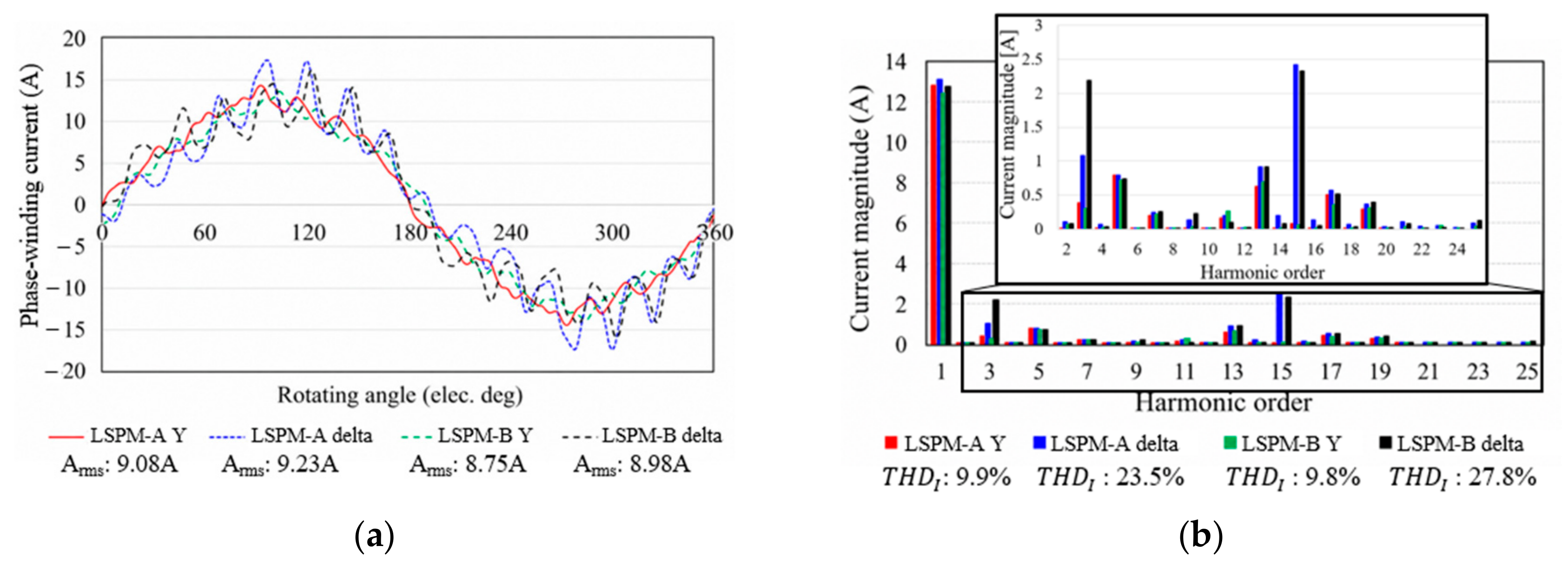
Figure 5 compares the phase-current waveforms and harmonic spectra of LSPM-A and LSPM-B under Y- and delta-connected winding conditions. As shown in Figure 5a, all cases exhibit similar fundamental-current profiles; however, the delta-connected cases show greater waveform distortion, particularly near the peak and zero-crossing regions. Figure 5b shows that the 3rd- and 15th-order harmonic components are considerably larger in the delta-connected cases. Accordingly, the current THD values of LSPM-A Y and LSPM-B Y are 9.96% and 9.81%, respectively, whereas those of LSPM-A delta and LSPM-B delta increase to 23.53% and 27.79%, as summarized in Table 2.
The analytical relationships presented in Section 2.4 explain the pronounced triplen harmonics under the delta-connected condition. Both the 3rd- and 15th-order components satisfy h = 3 k , where is a positive integer, and therefore correspond to zero-sequence harmonics. These currents cannot flow through the ungrounded Y connection because it does not provide a closed zero-sequence path. In contrast, they can circulate within the closed phase-winding branches of the delta connection [17]. Consequently, the current THD of the delta-connected case is approximately 2.36 and 2.83 times that of the corresponding Y-connected case for LSPM-A and LSPM-B, respectively. The FFT results in Figure 5 represent the phase-winding currents rather than the terminal line currents. Therefore, the zero-sequence components appear in the delta phase-winding currents even though they are canceled in the terminal line currents.
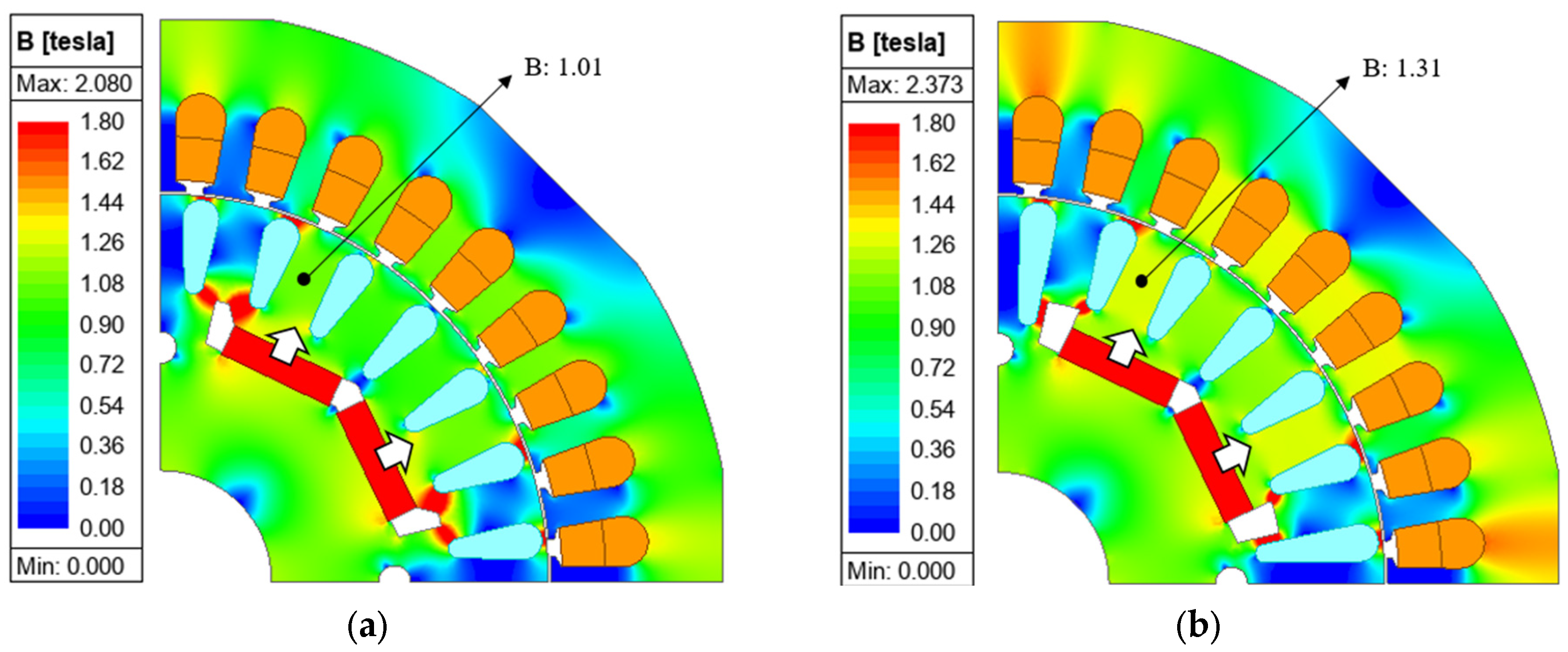
The RMS phase-winding currents of LSPM-A Y, LSPM-A delta, LSPM-B Y, and LSPM-B delta are 9.08, 9.23, 8.75, and 8.98 A, respectively. LSPM-B Y exhibits the lowest phase-winding current of 8.75 A. To examine the magnetic mechanism underlying this result, Figure 6 compares the magnetic flux-density distributions of LSPM-A Y and LSPM-B Y at the same steady-state rotor position and operating condition. In LSPM-A Y, the high-flux-density region extends through the internal iron path between the permanent-magnet end, flux barrier, and adjacent rotor bar, indicating a pronounced leakage-flux path. In LSPM-B Y, the enlarged flux barrier increases the reluctance of this leakage path and redirects a greater portion of the permanent-magnet flux toward the air gap. As a result, the main flux path between adjacent rotor bars exhibits higher flux density and stronger local saturation in Figure 6b than in Figure 6a. The maximum local flux densities are 2.080 T for LSPM-A Y and 2.373 T for LSPM-B Y. Thus, the modified rotor geometry redistributes, rather than uniformly reduces, magnetic saturation by restricting the internal leakage path and concentrating the flux along the air-gap-directed main path. This interpretation is consistent with the increase in induced phase voltage from 217.2 to 228.1 V rms discussed in Section 3.2 and supports the association between the lower phase-winding current of LSPM-B Y and its increased effective permanent-magnet flux linkage.
The stator copper-loss results are consistent with the phase-winding-current characteristics. The stator copper losses of LSPM-A Y and LSPM-B Y are 148.40 and 137.81 W, respectively, whereas those of LSPM-A delta and LSPM-B delta increase to 153.35 and 145.15 W. Based on Equation (10), the harmonic copper-loss ratios are 0.98%, 5.25%, 0.95%, and 7.17%, corresponding to harmonic copper losses of approximately 1.46, 8.04, 1.31, and 10.41 W, respectively. Changing the connection from Y to delta therefore increases the estimated harmonic copper loss by approximately 6.59 W for LSPM-A and 9.09 W for LSPM-B. Because these values were calculated from the total current THD under the constant phase-resistance assumption, they represent the aggregate contribution of all harmonic-current components rather than the isolated contributions of the 3rd and 15th harmonics. Furthermore, because the delta-branch circulating-current spectrum was not measured experimentally, these harmonic-current and copper-loss results should be regarded as numerical predictions under the specified FEA conditions.

3.2. Induced Phase Voltage Waveforms and Harmonic Characteristics

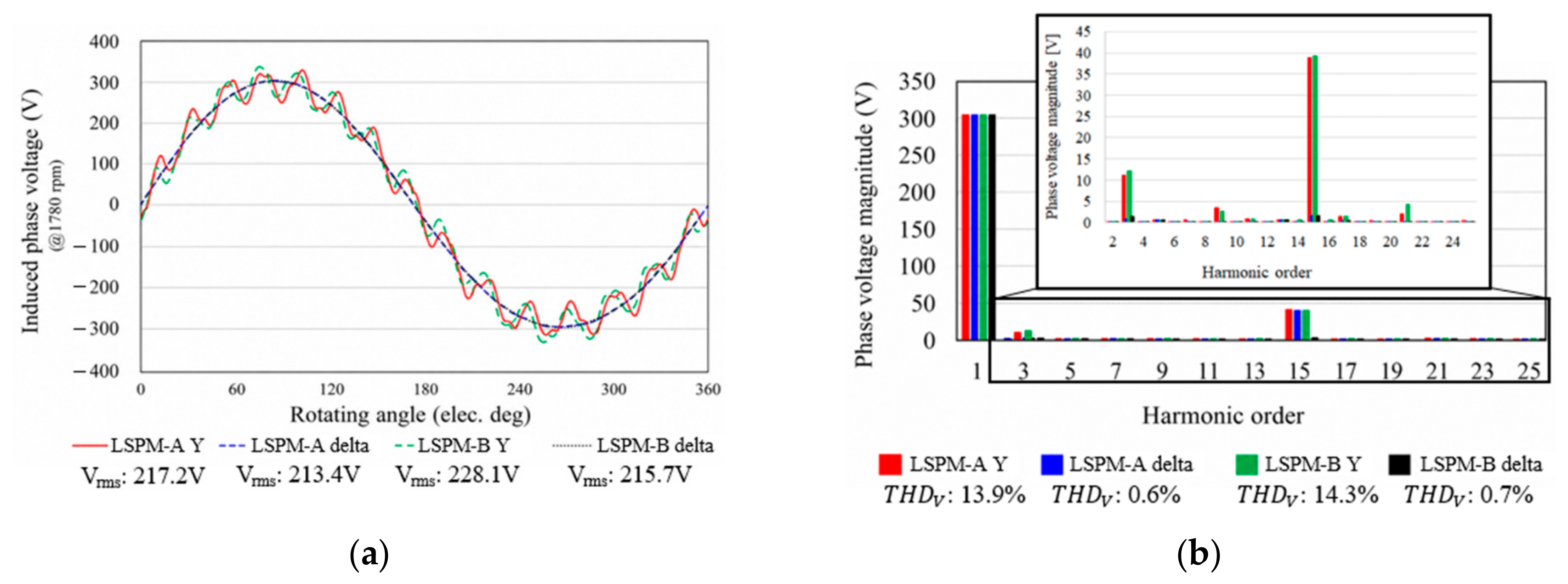
Figure 7 compares the induced phase-voltage characteristics of the LSPM-A and LSPM-B models under Y- and delta-connected conditions. The Y-connected cases show greater waveform distortion and more noticeable 3rd- and 15th-order harmonic components than the delta-connected cases. Accordingly, the voltage THD values of the LSPM-A Y and LSPM-B Y cases are 13.9% and 14.3%, respectively, whereas those of the delta-connected cases are below 1%, as summarized in Table 3. The low voltage THD of the delta-connected cases should be interpreted carefully because the voltage reference differs between the two connections. The Y-connected voltage is referenced to the neutral point, whereas the delta branch voltage corresponds to a line-to-line voltage, in which zero-sequence harmonic components can be suppressed. The LSPM-B Y case exhibits the highest induced phase voltage of 228.1 Vrms, compared with 217.2 Vrms for the LSPM-A Y case. This increase is attributed to reduced flux leakage around the flux-barrier and rotor-bar regions. In addition, the core loss decreases from 273.5 W to 265.9 W under the Y connection, indicating that the LSPM-B rotor structure mitigates local flux concentration and magnetic saturation. Therefore, the voltage and core-loss characteristics are determined by both the winding connection and rotor magnetic circuit.

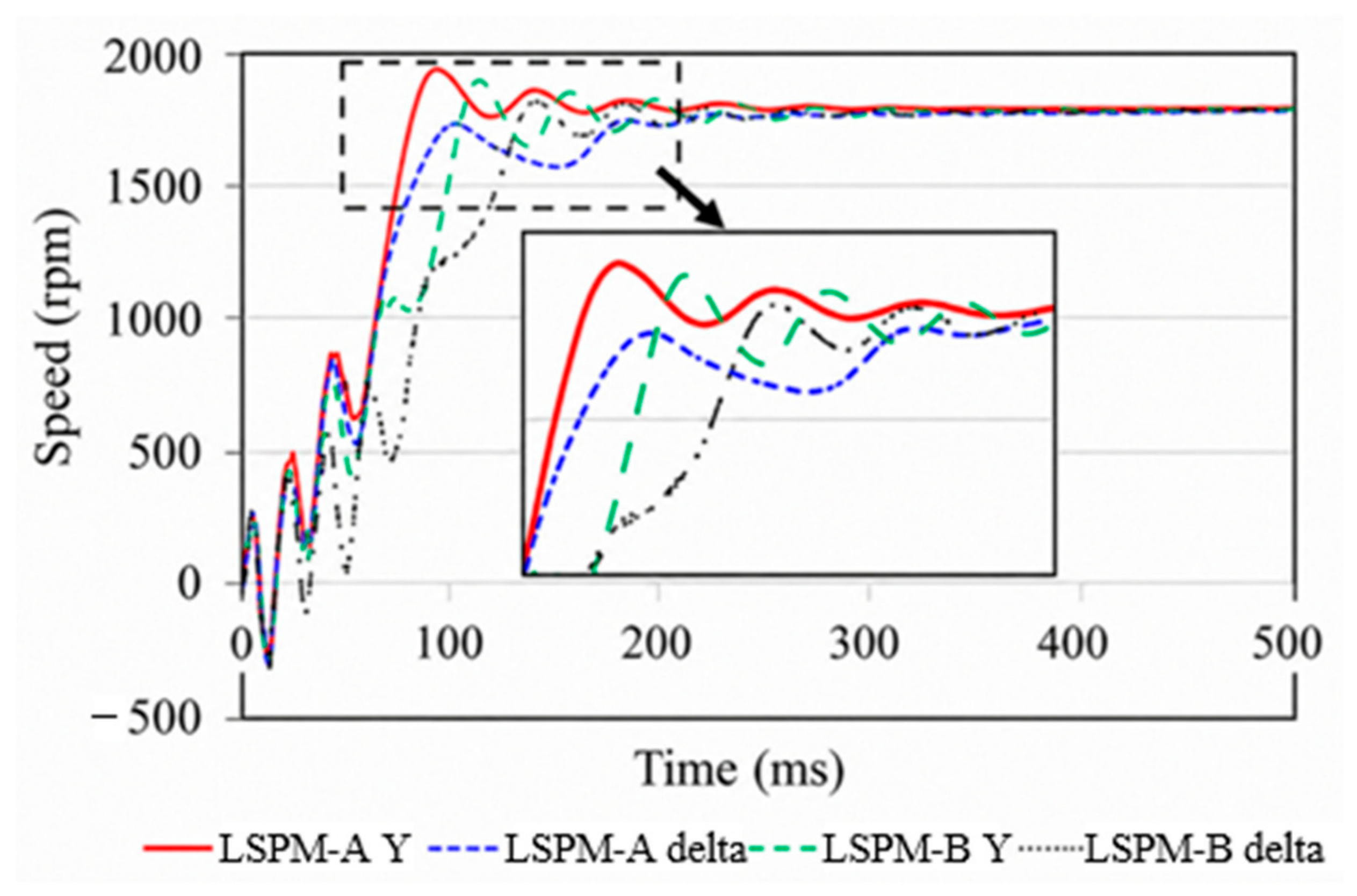
3.3. Quantitative Evaluation of Starting and Synchronization Characteristics

Figure 8 shows the transient speed responses of LSPM-A and LSPM-B under the Y- and delta-connected winding conditions. All cases accelerated from standstill and satisfied the ±1% settling criterion within the 500 ms simulation interval. The quantitative synchronization metrics are summarized in Table 4. The LSPM-A Y case reached a maximum speed of approximately 1950 rpm, corresponding to an overshoot of approximately 8.3%, and exhibited the shortest settling time of approximately 280 ms. In contrast, the LSPM-A delta case slightly exceeded the synchronous speed, resulting in an overshoot of only 0.5%, while its settling time increased to approximately 300 ms. For LSPM-B, the Y-connected case reached a maximum speed of approximately 1900 rpm, corresponding to an overshoot of approximately 5.6%. The delta-connected case reduced the maximum speed to approximately 1830 rpm and the overshoot to approximately 1.7%. The LSPM-B Y and LSPM-B delta cases satisfied the ±1% settling criterion at approximately 310 and 330 ms, respectively. These results demonstrate that the LSPM-A Y case provides the fastest synchronization response but produces the largest speed overshoot. According to the torque decomposition in Equation (12), the speed response is governed by the time integral of the net accelerating torque rather than by a single torque component. The rapid acceleration and large overshoot of LSPM-A Y indicate a relatively large positive net accelerating torque during pull-in. Changing the winding connection from Y to delta modifies the d - and q -axis stator currents and the induced cage-current response. Therefore, the lower overshoot of the delta-connected cases is consistent with a reduction in the maximum net accelerating torque near the synchronous speed. However, this reduction does not shorten the settling time. Consequently, the delta connection is advantageous for suppressing the maximum speed deviation during pull-in rather than providing faster synchronization. These results represent the intrinsic electromechanical response under identical direct-on-line conditions rather than the dynamic performance of a closed-loop controller.

3.4. Steady-State Torque Performance After Synchronization

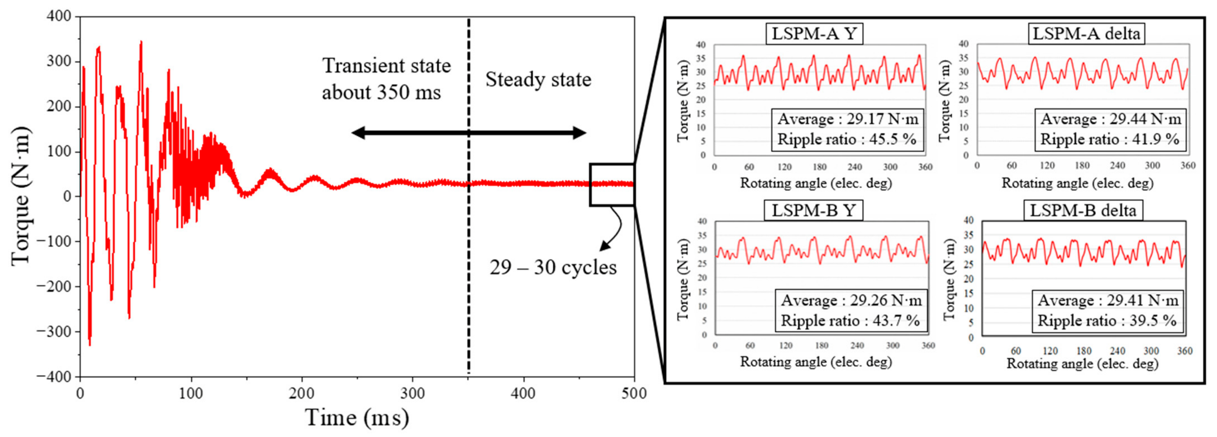
Figure 9 presents the transient torque responses and steady-state torque waveforms of LSPM-A and LSPM-B under the Y- and delta-connected winding conditions. The torque response exhibits large oscillations during the initial starting period, but the transient fluctuations gradually decrease as the rotor approaches the synchronous-speed region. After approximately 350 ms, the torque response converges to a periodic steady-state condition. Steady-state convergence was defined as a variation of less than 1% in the cycle-averaged torque over three consecutive electrical cycles. The relative variation was calculated as the difference between the maximum and minimum cycle-averaged torques divided by their mean value. This criterion was satisfied for the 28th–30th electrical cycles in all investigated cases. At 60 Hz, the 29th and 30th cycles correspond to 466.7–500 ms. Therefore, the torque waveforms during these two cycles were used to evaluate the steady-state average torque and torque-ripple characteristics.
The steady-state performance results, including the average torque, torque ripple ratio, phase-winding current, copper loss, and efficiency, are summarized in Table 5. The LSPM-A Y, LSPM-A delta, LSPM-B Y, and LSPM-B delta cases produce average torques of 29.17, 29.44, 29.26, and 29.41 N·m, respectively. Therefore, changing the rotor configuration and winding connection does not significantly affect the rated torque capability. The torque ripple ratio differs according to the winding connection. For the LSPM-A model, the torque ripple ratio decreases from 45.5% under the Y connection to 41.9% under the delta connection. Similarly, the LSPM-B model shows a reduction from 43.7% to 39.5% when the winding connection is changed from Y to delta. This reduction is attributed to the different stator current distribution and harmonic current paths associated with the delta connection, which modify the interaction between the stator MMF and rotor magnetic field. Regarding loss and efficiency, Table 5 shows that the LSPM-B Y case has the lowest phase-winding current and copper loss of 8.75 A and 137.81 W, respectively. As a result, it achieves the highest efficiency of 92.92%. In contrast, the delta-connected cases exhibit lower torque ripple but higher copper loss than the corresponding Y-connected cases because of the increased harmonic current components. These results indicate that the Y connection is advantageous for minimizing copper loss and maximizing steady-state efficiency, whereas the delta connection is favorable for reducing torque ripple at the synchronous speed.

3.5. Quantitative Interaction Between Winding Connection and Rotor Configuration

Table 6 summarizes the changes in the principal performance indices when the winding connection is changed from Y to delta. Positive values indicate an increase under the delta connection, whereas negative values indicate a decrease. For LSPM-A and LSPM-B, the current THD increases by 13.57 and 17.98 percentage points, respectively, resulting in an interaction contrast of 4.41 percentage points. Similarly, the stator copper-loss increases are 4.95 and 7.34 W, indicating that the harmonic-current penalty associated with the delta connection is more pronounced in LSPM-B. In contrast, the core loss decreases by 20.96 W for LSPM-A but by only 2.58 W for LSPM-B. This difference produces an interaction contrast of 18.38 W, demonstrating that the influence of the winding connection on the core loss strongly depends on the rotor magnetic circuit. The delta connection reduces the torque ripple ratio for both models, with reductions of 3.6 and 4.2 percentage points for LSPM-A and LSPM-B, respectively. The corresponding interaction contrast is only −0.6 percentage points, indicating a relatively consistent torque-ripple reduction across the two rotor models. The maximum speed overshoot decreases by 7.8 percentage points for LSPM-A and by 3.9 percentage points for LSPM-B, whereas the settling time increases by 20 ms for both models. Therefore, the effect of the delta connection on maximum speed deviation is rotor-dependent, while its effect on the settling time is similar for the two investigated configurations. These results demonstrate that neither winding connection is universally superior. Instead, the connection-dependent performance trade-off varies according to the rotor magnetic circuit and the performance index considered.

4. Limited Experimental Verification of LSPM-B Y

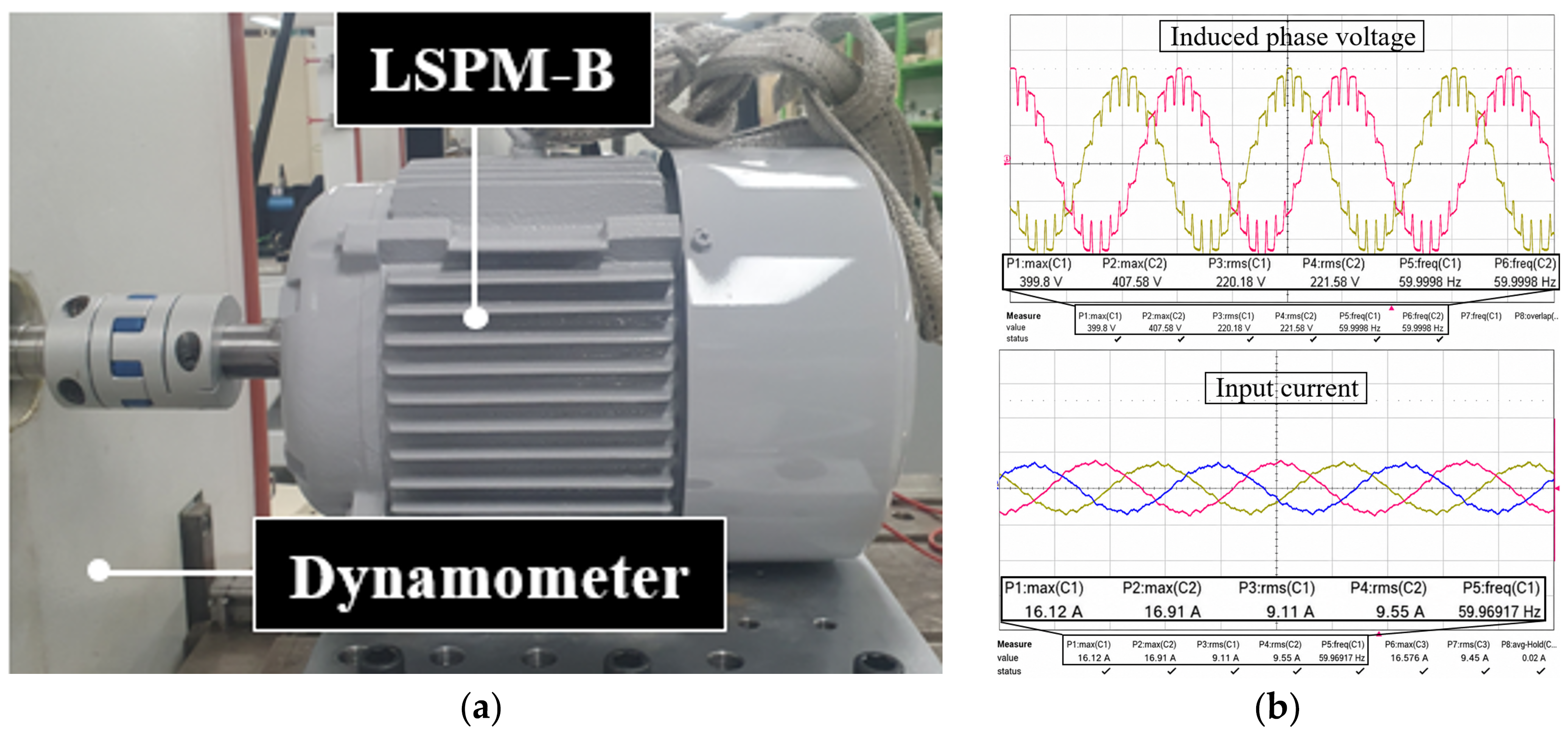
Figure 10 presents the experimental setup and measured waveforms of the LSPM-B Y-connected prototype. As shown in Figure 10a, the prototype was mechanically coupled to a dynamometer. The available experiment was limited to the LSPM-B Y-connected case and was conducted to provide a quantitative consistency check between the measured results and the corresponding FEA model. Therefore, the experiment does not directly validate the predicted performance differences between the Y- and delta-connected cases. The connection-dependent results for current harmonics, losses, torque ripple, and synchronization response should accordingly be interpreted as numerical predictions under the specified FEA conditions. Figure 10b shows the measured phase-voltage and phase-winding-current waveforms. The measured phase-voltage RMS values were 220.18 and 221.58 Vrms for Channels 1 and 2, respectively, at an operating frequency of approximately 60 Hz. The average measured phase voltage was therefore 220.9 Vrms. Compared with the corresponding FEA result of 228.1 Vrms, the measured value was approximately 3.2% lower. The measured RMS phase-winding currents were 9.11, 9.55, and 9.45 A, resulting in an average value of approximately 9.37 A. The corresponding FEA result was 8.75 A, and the measured current was approximately 7.1% higher than the numerical result. The relative error between the FEA and experimental results was calculated as
ε X = | X e x p X F E A X F E A | × 100
where X e x p and X F E A represent the experimental and FEA values, respectively. Table 7 summarizes the quantitative comparison.
The differences between the FEA and experimental results can be attributed to several factors. The two-dimensional FEA model assumes a uniform axial geometry and does not fully represent end effects, end-winding leakage, manufacturing tolerances, mechanical losses, and temperature-dependent winding resistance. In addition, deviations in the actual permanent-magnet properties, air-gap length, supply-voltage balance, and material characteristics can affect the measured voltage and current. Despite these practical differences, the measured values showed errors of less than 8% compared with the corresponding FEA results, indicating reasonable agreement for the LSPM-B Y-connected model. The experimental results provide a limited consistency check only for the electromagnetic FEA model of the LSPM-B Y-connected prototype. Therefore, they do not directly verify all comparative results between the Y- and delta-connected cases. The connection-dependent trends in current harmonics, torque ripple, loss, and synchronization response should be interpreted as numerical predictions under the specified FEA conditions. Furthermore, the zero-sequence circulating-current spectrum in the delta winding and the multi-point temperature distribution during long-term operation were not measured. Consequently, the present experimental results do not directly verify the predicted harmonic-loss increase or the thermal differences between the Y- and delta-connected windings. Dedicated delta-branch current measurements and multi-point temperature measurements are therefore required in future work. Nevertheless, the agreement between the measured and calculated values supports the use of the LSPM-B Y-connected FEA model as a basis for the comparative numerical analysis.

5. Conclusions

This study investigated the effects of Y- and delta-connected stator windings on the electromagnetic performance of LSPMs with different rotor geometries. The comparison between LSPM-A and LSPM-B demonstrated that the effects of the winding connection depend on the permanent-magnet flux path, rotor-bar geometry, and cage-assisted starting characteristics. Under the investigated 60 Hz rated-load condition, the Y-connected cases exhibited lower current distortion and copper loss, resulting in higher steady-state efficiency. In contrast, the delta-connected cases reduced torque ripple and maximum speed overshoot during synchronization, although their settling times were slightly longer. The LSPM-B rotor geometry restricted the internal leakage-flux path around the flux-barrier and rotor-bar regions and redirected a greater portion of the permanent-magnet flux toward the air gap. Consequently, the LSPM-B Y case achieved the highest efficiency of 92.92%. The measured voltage and current of the LSPM-B Y-connected prototype showed limited quantitative consistency with the corresponding FEA results.
Unlike previous studies that primarily focused on rotor-geometry optimization or winding-connection switching for efficiency improvement, this study examined the combined effects of winding connection and rotor geometry on current harmonics, magnetic-flux distribution, losses, torque ripple, and intrinsic direct-on-line synchronization response. The results provide design considerations for selecting a stator winding connection according to the required balance among steady-state efficiency, harmonic loss, torque ripple, and transient speed deviation. The interaction analysis further showed that the Y-to-delta changes in current THD, stator copper loss, core loss, and maximum speed overshoot differed between LSPM-A and LSPM-B. In contrast, the settling-time increase was identical for the two models. These findings confirm that the winding-connection effect cannot be separated from the rotor magnetic circuit, although the interaction contrasts obtained in this study are limited to the two investigated rotor configurations. However, the present conclusions are limited to the specified 60 Hz rated-load condition and should not be generalized to the entire operating range. Further numerical and experimental investigations under light-load, partial-load, and overload conditions are required to establish load-dependent winding-connection selection criteria.

Author Contributions

Conceptualization, S.-H.L.; Methodology, S.-H.L. and S.-W.S.; Software, I.-J.Y.; Validation, S.-H.L. and I.-J.Y.; Formal Analysis, I.-J.Y.; Investigation, S.-H.L. and I.-J.Y.; Resources, S.-H.L. and I.-J.Y.; Data Curation, I.-J.Y.; Writing—Original Draft, S.-H.L. and I.-J.Y.; Writing—Review and Editing, S.-H.L. and S.-W.S.; Visualization, S.-W.S.; Supervision, S.-W.S.; Project Administration, S.-W.S.; Funding Acquisition, S.-W.S. All authors have read and agreed to the published version of the manuscript.

Funding

This research received no external funding.

Data Availability Statement

The original contributions presented in this study are included in the article; further inquiries can be directed to the corresponding author.

Acknowledgments

This research was supported by the Regional Innovation System & Education (RISE) program through the Chungbuk Regional Innovation System & Education Center, funded by the Ministry of Education (MOE) and the Chungcheongbuk-do, Republic of Korea (2026-RISE-11-013-03). This work was also supported by a Korea Institute of Energy Technology Evaluation and Planning (KETEP) grant funded by the Korea government (MOTIE) (RS-2024-00419152, Development of 5 kW industrial logistics electric platform technology).

Conflicts of Interest

The authors declare no conflicts of interest.

References

  1. Richter, E.; Neumann, T.W. Line Start Permanent Magnet Motors with Different Materials. IEEE Trans. Magn. 1984, 20, 1762–1764. [Google Scholar] [CrossRef] [Scilit]
  2. Palangar, M.F.; Soong, W.L.; Bianchi, N.; Wang, R.-J. Design and Optimization Techniques in Performance Improvement of Line-Start Permanent Magnet Synchronous Motors: A Review. IEEE Trans. Magn. 2021, 57, 900214. [Google Scholar] [CrossRef] [Scilit]
  3. Yan, B.; Li, X.; Wang, X.; Yang, Y.; Chen, D. Magnetic Field Prediction for Line-Start Permanent Magnet Synchronous Motor via Incorporating Geometry Approximation and Finite Difference Method Into Subdomain Model. IEEE Trans. Ind. Electron. 2023, 70, 2843–2854. [Google Scholar] [CrossRef] [Scilit]
  4. Aliabad, A.D.; Mirsalim, M.; Ershad, N.F. Line-Start Permanent-Magnet Motors: Significant Improvements in Starting Torque, Synchronization, and Steady-State Performance. IEEE Trans. Magn. 2010, 46, 4066–4072. [Google Scholar] [CrossRef] [Scilit]
  5. Hassanpour Isfahani, A.; Vaez-Zadeh, S. Effects of Magnetizing Inductance on Start-Up and Synchronization of Line-Start Permanent-Magnet Synchronous Motors. IEEE Trans. Magn. 2011, 47, 823–829. [Google Scholar] [CrossRef] [Scilit]
  6. Takahashi, A.; Kikuchi, S.; Miyata, K. Asynchronous Torque of Line-Starting Permanent-Magnet Synchronous Motors. IEEE Trans. Energy Convers. 2015, 30, 498–506. [Google Scholar] [CrossRef] [Scilit]
  7. Yan, B.; Li, X.; Wang, X.; Yang, Y.; Chen, D. An Improved 2-D Subdomain Method Toward Electromagnetic-Performance Analysis of Line-Start Permanent Magnet Synchronous Motor. IEEE Trans. Transp. Electrif. 2023, 9, 4339–4351. [Google Scholar] [CrossRef] [Scilit]
  8. Yang, Y.; Yan, B.; Wang, X. Dynamic Model of a Line-Start Permanent Magnet Synchronous Motor Equipped With Hybrid Rotor. IEEE Trans. Transp. Electrif. 2024, 10, 2974–2987. [Google Scholar] [CrossRef] [Scilit]
  9. Barta, J.; Knebl, L.; Bramerdorfer, G.; Lolova, I.; Silber, S.; Vitek, O. Topology Optimization of Rotor Bars Geometry and Arrangement for a Line-Start Permanent Magnet Synchronous Machine. IEEE Access 2021, 9, 115192–115204. [Google Scholar] [CrossRef] [Scilit]
  10. Zhao, Y.; Li, D.; Lin, M.; Qu, R. Investigation of Line-Start Permanent Magnet Vernier Machine With Different Rotor Topologies. IEEE J. Emerg. Sel. Top. Power Electron. 2022, 10, 2859–2870. [Google Scholar] [CrossRef] [Scilit]
  11. Sarani, E.; Vaez-Zadeh, S. Design Procedure and Optimal Guidelines for Overall Enhancement of Steady-State and Transient Performances of Line Start Permanent Magnet Motors. IEEE Trans. Energy Convers. 2017, 32, 885–894. [Google Scholar] [CrossRef] [Scilit]
  12. Li, L.; Fu, W.; Niu, S. Novel Steel-Bar Starting Cage Line-Start Permanent Magnet Machine With Spoke-Type Insulation Layers. IEEE Trans. Magn. 2022, 58, 8204405. [Google Scholar] [CrossRef] [Scilit]
  13. Gnaciński, P.; Muc, A.; Pepliński, M. Influence of Voltage Subharmonics on Line Start Permanent Magnet Synchronous Motor. IEEE Access 2021, 9, 164275–164281. [Google Scholar] [CrossRef] [Scilit]
  14. Qiu, H.; Zhang, Y.; Hu, K.; Yang, C.; Yi, R. The Influence of Stator Winding Turns on the Steady-State Performances of Line-Start Permanent Magnet Synchronous Motors. Energies 2019, 12, 2363. [Google Scholar] [CrossRef] [Scilit]
  15. Ferreira, F.J.T.E.; Ge, B.; de Almeida, A.T. Stator Winding Connection-Mode Management in Line-Start Permanent Magnet Motors to Improve Their Efficiency and Power Factor. IEEE Trans. Energy Convers. 2013, 28, 523–534. [Google Scholar] [CrossRef]
  16. Yan, B.; Yang, Y.; Wang, X. Design of a Large Capacity Line-Start Permanent Magnet Synchronous Motor Equipped With Hybrid Salient Rotor. IEEE Trans. Ind. Electron. 2021, 68, 6662–6671. [Google Scholar] [CrossRef] [Scilit]
  17. Abramenko, V.; Petrov, I.; Nerg, J.; Pyrhönen, J. Third-Order Harmonics in Synchronous Reluctance Motors With an Axially Laminated Anisotropic Rotor and Their Impact on the Motor Losses. IEEE Access 2020, 8, 152870–152880. [Google Scholar] [CrossRef] [Scilit]
  18. Zhou, Y.; Huang, K.; Sun, P.; Dong, R. Analytical Calculation of Performance of Line-Start Permanent-Magnet Synchronous Motors Based on Multidamping-Circuit Model. IEEE Trans. Power Electron. 2021, 36, 4410–4419. [Google Scholar] [CrossRef] [Scilit]
  19. Zhou, Y.; Yang, X. Analytical Method to Calculate Inductances of Spoke-Type Permanent-Magnet Synchronous Motors With Damping Bars. IEEE Trans. Ind. Electron. 2023, 70, 8254–8263. [Google Scholar] [CrossRef] [Scilit]
  20. Friedrich, L.A.J.; Hameyer, K. High-Order Methods Applied to Nonlinear Magnetostatic Problems with Magnetic Saturation. Mathematics 2019, 7, 19. [Google Scholar]
Figure 1. Comparison of the configurations: (a) conventional IM; (b) LSPM-A.
Actuators 15 00462 g001
Figure 2. Rotor configurations of the investigated LSPMs: (a) LSPM-A; (b) LSPM-B.
Actuators 15 00462 g002
Figure 3. Stator winding connection configurations: (a) Y connection; (b) delta connection.
Actuators 15 00462 g003
Figure 4. Mesh distribution of LSPM.
Actuators 15 00462 g004
Figure 5. Phase current waveforms and harmonic spectra of the investigated LSPM models under Y- and delta-connected winding conditions (a) phase current waveforms (b) FFT results.
Actuators 15 00462 g005
Figure 6. Magnetic flux-density distributions under the Y-connected condition: (a) LSPM-A Y; (b) LSPM-B Y.
Actuators 15 00462 g006
Figure 7. Induced phase voltage waveforms and harmonic spectra of the investigated LSPM models under Y- and delta-connected winding conditions: (a) induced phase voltage waveforms; (b) FFT results.
Actuators 15 00462 g007
Figure 8. Speed responses of the LSPM-A and LSPM-B models under Y- and delta-connected winding conditions during starting and synchronization.
Actuators 15 00462 g008
Figure 9. Transient torque response and steady-state torque ripple comparison of the LSPM-A and LSPM-B models under Y- and delta-connected winding conditions.
Actuators 15 00462 g009
Figure 10. Limited experimental verification of the LSPM-B Y-connected model: (a) prototype and dynamometer setup, and (b) measured phase-voltage and phase-winding-current waveforms.
Actuators 15 00462 g010
Table 1. Performance comparison of conventional IM and LSPM-A.
ParameterConventional IMLSPM-AUnit
SizeInner/Outer diameter of stator150/220mm
Inner/Outer diameter of rotor43/149mm
Stack length120mm
MaterialStator/Rotor50PN470-
CoilCopper-
MagnetN35UH-
SpecificationPole/Slot4/36-
Voltage380V
Speed17801780rpm
Torque29.229.44N·m
Current11.59.08Arms
Output power54495524W
Efficiency89.3392.6%
Table 2. Comparison of current harmonic distortion and copper loss under different stator winding connections.
T H D I (%)Phase-Winding Current (Arms)Copper Loss (W)Harmonic Copper-Loss Ratio
(%)
Harmonic Copper Loss
(W)
LSPM-A Y9.969.08148.40.981.46
LSPM-A delta23.539.23153.355.258.04
LSPM-B Y9.818.75137.810.951.31
LSPM-B delta27.798.98145.157.1710.41
Table 3. Comparison of induced phase voltage, voltage harmonic distortion, and core loss under different stator winding connections.
Induced Phase Voltage (Vrms) T H D V (%)Core Loss (W)
LSPM-A Y217.213.9273.5
LSPM-A delta213.40.6252.6
LSPM-B Y228.114.3265.9
LSPM-B delta215.70.7263.4
Table 4. Quantitative synchronization metrics for LSPM-A and LSPM-B under Y- and delta-connected winding conditions.
Maximum Speed (rpm)Maximum Overshoot (%) ± 1% Settling Time (ms)
LSPM-A Y19508.3280
LSPM-A delta17900.5300
LSPM-B Y19005.6310
LSPM-B delta18301.7330
Table 5. Steady-state electromagnetic performance comparison of the conventional IM and LSPM models under different stator winding connections.
Phase-Winding
Current (Arms)
Copper Loss (W)Core Loss (W)Torque
(N·m)
Torque Ripple Ratio
(%)
Output (kW)Efficiency (%)
IM11.5238.05224.5229.2430.85.4589.33
LSPM-A Y9.08148.4273.5629.1745.55.5292.6
LSPM-A delta9.23153.35252.629.4441.95.5292.54
LSPM-B Y8.75137.81265.9429.2643.75.5592.92
LSPM-B delta8.98145.15263.3629.4139.55.5392.64
Table 6. Connection-induced performance changes and interaction contrasts between LSPM-A and LSPM-B.
Performance Index Δ X A Δ X B Γ X
Current THD (%p)+13.57+17.98+4.41
Stator copper loss (W)+4.95+7.34+2.39
Core loss (W) 20.96 2.58+18.38
Torque ripple ratio (%p) 3.6 4.2 0.6
Efficiency (%p) 0.06 0.28 0.22
Maximum speed overshoot (%p) 7.8 3.9+3.9
Settling time (ms)+20+200
Table 7. Quantitative comparison between FEA and experimental results for the LSPM-B Y-connected model.
ParameterFEAExperimentRelative Error (%)
Phase voltage (Vrms)228.1220.93.2
RMS phase-winding current (Arms)8.759.377.1
Disclaimer/Publisher’s Note: The statements, opinions and data contained in all publications are solely those of the individual author(s) and contributor(s) and not of MDPI and/or the editor(s). MDPI and/or the editor(s) disclaim responsibility for any injury to people or property resulting from any ideas, methods, instructions or products referred to in the content.