1. Introduction
Low-speed, high-torque drives are widely required in direct-drive wind turbines, marine propulsion, heavy agricultural machinery, mining equipment, and industrial actuators. Conventional solutions generally combine a high-speed motor with a mechanical gearbox. However, the gearbox introduces additional transmission loss, vibration, noise, and maintenance requirements, thereby reducing the reliability and life-cycle efficiency of the drive system [
1]. Field modulation permanent magnet (PM) motors (FMPMMs), including PM vernier motors, utilize the interaction between magnetomotive force (MMF) harmonics and air-gap permeance harmonics to obtain an inherent magnetic gearing effect. They can therefore produce high torque at a relatively low mechanical speed and are promising candidates for gearless direct-drive systems [
2].
Most conventional FMPMMs employ unidirectional field modulation. They can be divided into rotor PM and stator PM structures according to PM placement positions, yet both categories face inherent performance limitations. Rotor PM field modulation motors (RFMPMMs) feature high air-gap flux density and strong torque output capacity, while the rotor PM suffers poor heat dissipation and severe local magnetic saturation under heavy loads, bringing irreversible demagnetization risks and restricting the upper limit of torque density [
3]. Stator PM field modulation motors (SFMPMMs) fix PMs on the stationary stator side to optimize heat dissipation conditions, yet the limited installation space between stator slots and armature windings limits PM usage, resulting in insufficient fundamental air-gap flux density and weak torque output [
4]. To overcome the performance trade-offs of single-sided modulation topologies, scholars have proposed bidirectional magnetic field modulation technologies, which enable mutual magnetic field modulation between stator and rotor PMs to enrich effective torque harmonics and improve rare-earth utilization efficiency, becoming a hot research topic of high-torque-density FMPMMs in recent years.
At present, a variety of bidirectional field modulation topologies have been developed [
5,
6,
7], including hybrid excitation bidirectional modulation motors, double-stator dual-PM bidirectional modulation motors, dual-rotor magnetic field modulation motors and conventional integral-tooth bidirectional modulation motors, all of which have obvious technical bottlenecks that restrict engineering promotion. Hybrid excitation bidirectional modulation motors adopt the combination of PM and electric excitation windings to flexibly adjust air-gap flux density, but additional excitation windings increase copper loss, winding end volume and structural complexity [
8], and the electric excitation magnetic field will partially offset the PM magnetic field, reducing the utilization rate of rare-earth materials. Double-stator dual-PM bidirectional modulation motors can achieve enhanced bidirectional flux modulation capability, but the inherent drawbacks brought by the double-concentric stator layout cannot be ignored. The double-stator structure leads to an excessively long motor axial length, weak mechanical strength of stator winding ends, complicated assembly process and high manufacturing cost [
9]. Additionally, the superposition of counter-directional magnetic fields in the dual-stator magnetic circuit triggers partial flux cancellation, further lowering torque output per unit PM volume. Dual-rotor bidirectional modulation motors rely on two rotating rotors to realize the mutual modulation of multiple magnetic fields. However, the dual-rotor configuration involves two rotating components and two air gaps, resulting in a more complicated manufacturing process, significant electromagnetic coupling, and complex variations in motor parameters [
10]. Moreover, the inner rotor suffers from more severe thermal problems than those in conventional motors because of its restricted heat-transfer paths [
11]. For conventional integral-tooth bidirectional modulation motors without split teeth, the integral stator tooth limits the adjustable range of air-gap permeance harmonics. The number and amplitude of available torque harmonics are insufficient, so the improvement in torque density is limited, and torque ripple suppression effect is unsatisfactory under rated load.
To alleviate the above deficiencies in existing bidirectional field modulation motors, split-tooth stator structures are introduced to reconstruct air-gap permeance distribution. By splitting a single integral stator tooth into multiple sub-teeth, abundant high-order permeance harmonics can be generated to amplify the utilization of effective torque harmonics [
12,
13]. Meanwhile, the reserved space between split sub-teeth provides extra mounting positions for auxiliary PMs, which can further enhance the bidirectional magnetic field modulation effect without expanding the overall motor size. Existing research has confirmed that split-tooth structures can effectively boost the torque output of field modulation motors, but current studies still have prominent research gaps in the field of bidirectional modulation split-tooth motors. Most split-tooth FMPMM research only focuses on single-sided modulation modes, and few studies systematically explore the coupling mechanism between split-tooth structures and bidirectional mutual magnetic modulation. Since different pole–slot ratios dominate the coupling characteristics of stator and rotor magnetic fields [
14], the matching principle between split-tooth stators and diverse slot–pole configurations remains unclear. In addition, there is a lack of split-tooth bidirectional modulation topology that can simultaneously achieve high torque density, low PM consumption and low torque ripple. This series of research deficiencies limits the performance breakthrough of split-tooth bidirectional field modulation motors for low-carbon direct-drive applications.
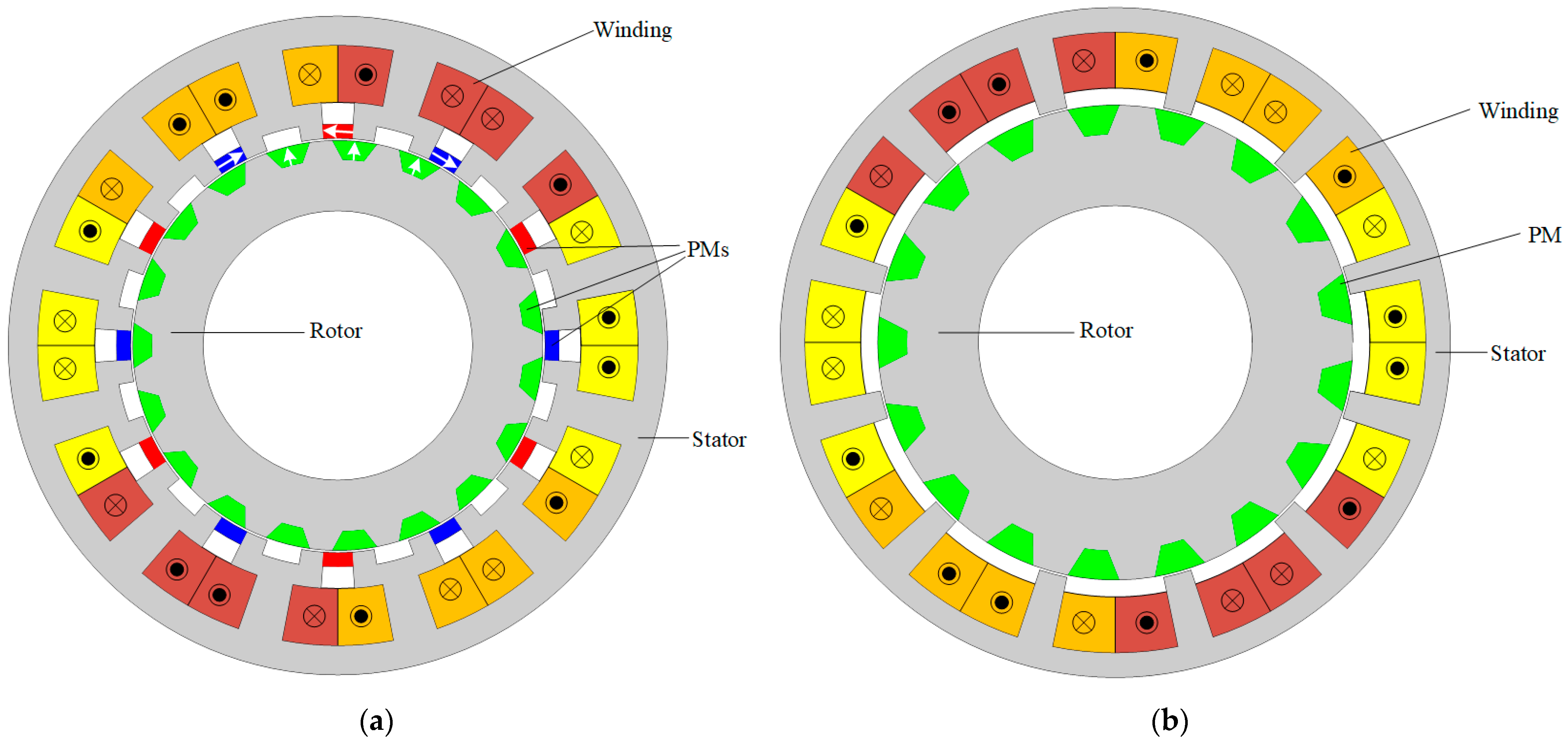
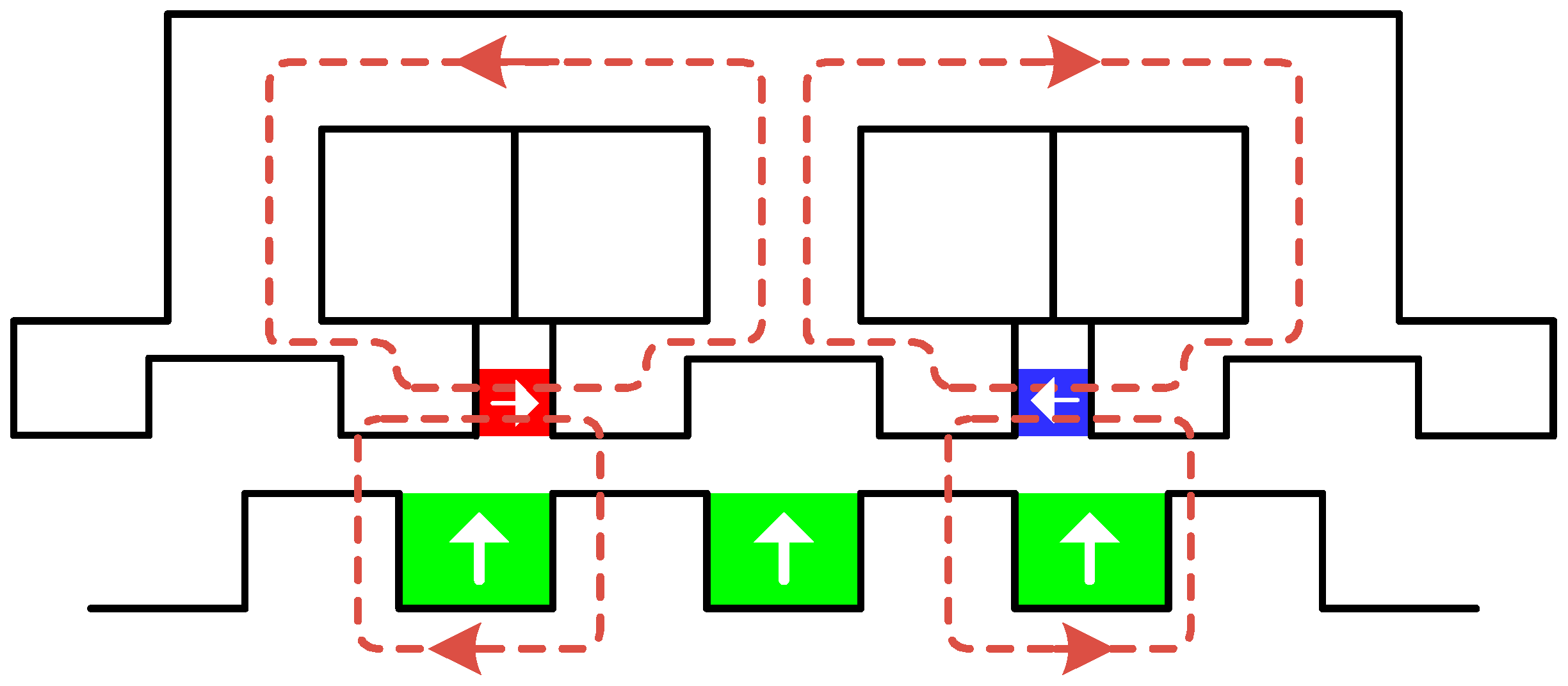
In order to solve the above technical problems and research deficiencies, this paper proposes a novel split-tooth bidirectional field modulation PM motor (ST-BFMPMM) with a simple single-stator, single-rotor topology for low-speed, high-torque, direct-drive applications. The proposed motor adopts a split-tooth stator structure, and tangentially magnetized PMs are embedded in the slot openings between split teeth. The rotor adopts a consequent-pole structure with radially embedded PMs. Compared with the double-stator and dual-rotor bidirectional modulation motors discussed above, the proposed topology retains a single-stator, single-rotor, and single-air-gap configuration, thereby providing a more compact magnetic circuit and avoiding the additional assembly, mechanical, and thermal difficulties associated with multiple stators, rotors, and air gaps. This topology realizes a bidirectional magnetic field modulation mechanism, which greatly enriches the air-gap flux harmonics and maximizes the utilization of torque-effective harmonics. The split-tooth structure further amplifies the permeance harmonics, so as to achieve high torque density under the condition of controlling PM consumption.
The main contributions of this paper are summarized as follows.
- (1)
A compact single-stator, single-rotor ST-BFMPMM is developed, and its bidirectional field modulation mechanism is derived using MMF permeance theory.
- (2)
Three candidate pole–slot combinations, namely 12-slot/14-pole (12s14p), 12-slot/17-pole (12s17p), and 12-slot/19-pole (12s19p) configurations, are optimized by finite element analysis (FEA), with average torque maximization and torque ripple minimization as the objectives, to clarify the influence of rotor pole number on the split-tooth bidirectional modulation effect.
- (3)
After identifying the 12s19p configuration as the best candidate, its no-load, rated-load, overload, efficiency map, torque–speed, magnetic saturation, and high-temperature demagnetization characteristics are systematically evaluated against those of a conventional 12s17p RFMPMM without split teeth or stator slot PMs.
To quantitatively highlight the fundamental innovations and performance superiority of the proposed ST-BFMPMM, a comprehensive qualitative and quantitative comparison is conducted. The detailed topological characteristics, operating harmonic performance, electromagnetic output characteristics, and research verification status are summarized in
Table 1.
The remainder of this paper is organized as follows.
Section 2 presents the topology of the proposed ST-BFMPMM and derives its bidirectional field modulation mechanism using MMF permeance theory.
Section 3 defines the optimization variables and objectives, compares the three pole–slot combinations, and identifies the optimal configuration.
Section 4 compares the no-load and load electromagnetic performance, PM utilization, efficiency maps, and torque–speed characteristics of the proposed and baseline motors.
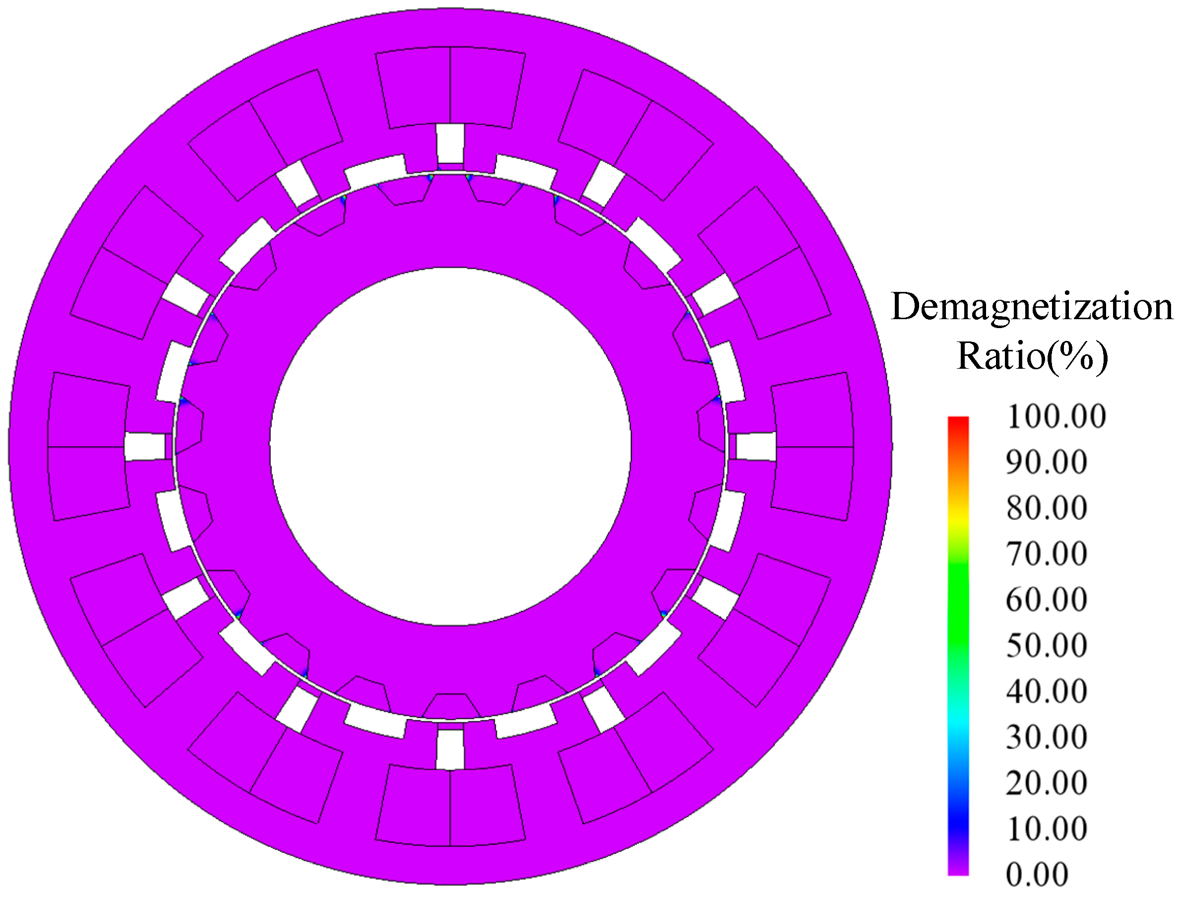
Section 5 evaluates local magnetic saturation under rated and 150% overload conditions and investigates irreversible demagnetization under the combined stresses of 150% overload current and a PM temperature of 120 °C.
Section 6 summarizes the main findings and discusses future measures for suppressing high-order harmonic losses and extending the high-efficiency operating range.
3. Pole–Slot Combination Optimization and Motor Design
According to the bidirectional field modulation principle established in
Section 2, the effective working harmonic pole-pair numbers are given by Equation (10). To maximize the torque output, three rotor pole numbers are considered: 14, 17, and 19, resulting in three ST-BFMPMM variants with 12s14p, 12s17p and 12s19p configurations. All three motors share the same topological features: a split-tooth stator with tangentially magnetized slot PMs and a consequent-pole rotor with radially embedded PMs. However, their geometric parameters are individually optimized for each rotor pole number. Based on the modulation conditions, the armature winding is designed with two-pole-pair winding for the 12s14p motor, while both the 12s17p and 12s19p motors adopt five-pole-pair windings.
3.1. Optimization Variables and Objectives
All three candidate motors have the same stator outer radius (61 mm), air-gap length (0.5 mm), and rotor inner radius (25 mm) to ensure a fair comparison. A total of 11 geometric parameters, including both stator and rotor variables, are selected for optimization.
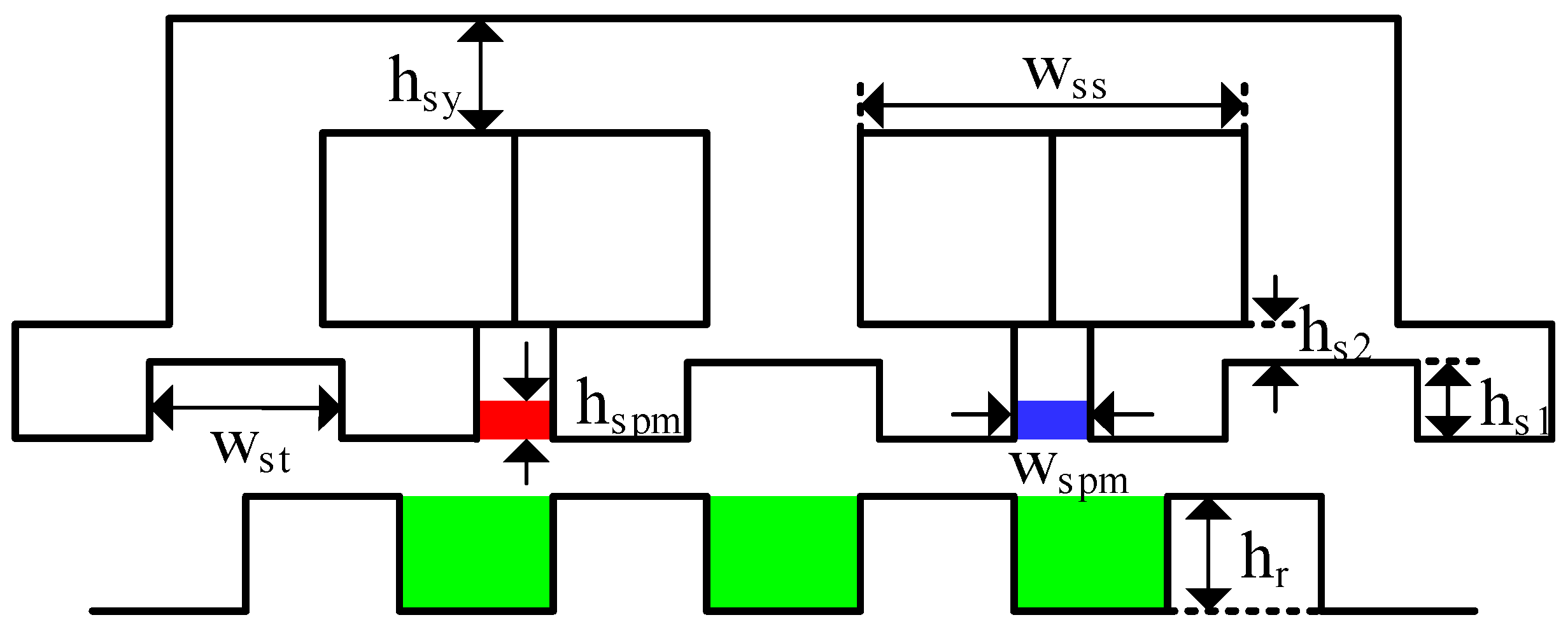
Figure 4 shows these 11 optimization variables on the cross-section of the proposed ST-BFMPMM. The variables are rotor outer radius (
Rro), rotor tooth height (
hr), rotor tooth inner arc angle (α
ri), rotor tooth outer arc angle (α
ro), stator yoke thickness (h
sy), stator PM height (
hspm), slot width (
wss), stator PM width (
wspm) and parameters of the split tooth dimensions (
hs1,
hs2,
wst).
The optimization is performed using an FEA-coupled multi-objective genetic algorithm (MOGA) with two objectives: maximizing the average torque at the rated condition (6 A, 400 rpm) and minimizing the torque ripple. For each pole–slot configuration, the population size is set to 20, and the maximum number of generations is set to 100. To assess the convergence, an additional 120-generation calculation is performed for the selected 12s19p configuration using the same population size and algorithm parameters. The maximum average torque and minimum torque ripple are obtained at generations 68 and 89, respectively, and neither is improved after generation 100, confirming that 100 generations provide a reasonable balance between convergence and the computational cost of the coupled FEA. The MOGA generates a Pareto front representing the trade-off between average torque and torque ripple. The design with the highest average torque while keeping the torque ripple below 5% is selected as the final design for that combination.
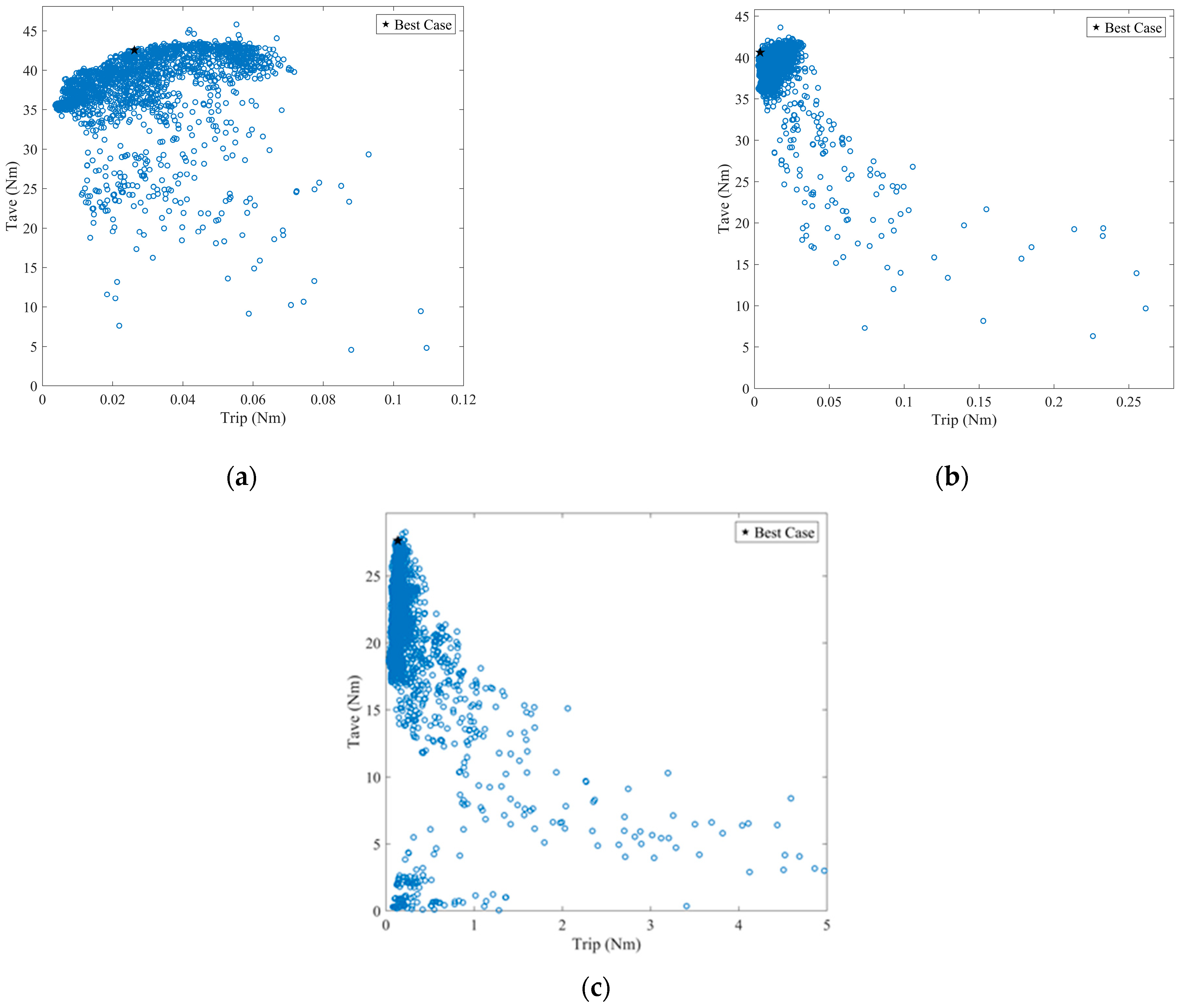
As shown in
Figure 5, the distribution characteristics of Pareto optimal solutions differ among the three schemes. Considering the practical operation requirement of motors, the design cases with extremely high torque ripple are screened out for the 12s14p ST-BFMPMM, since excessive torque ripple will seriously degrade the operating stability. In contrast, the 12s17p ST-BFMPMM and 12s19p ST-BFMPMM reserve the complete sets of feasible solutions without artificial elimination. Additionally, all candidate designs are restricted with a fixed armature winding area of approximately 100 mm
2 to guarantee fair comparison of electromagnetic performance. Each scheme selects the optimal design under the constraint that torque ripple is lower than 5% and average torque is maximized. Relevant performance comparison and scheme selection will be presented in the following part.
3.2. Torque Performance Comparison
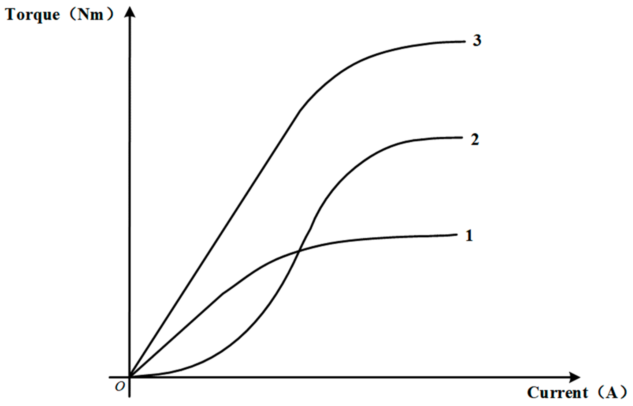
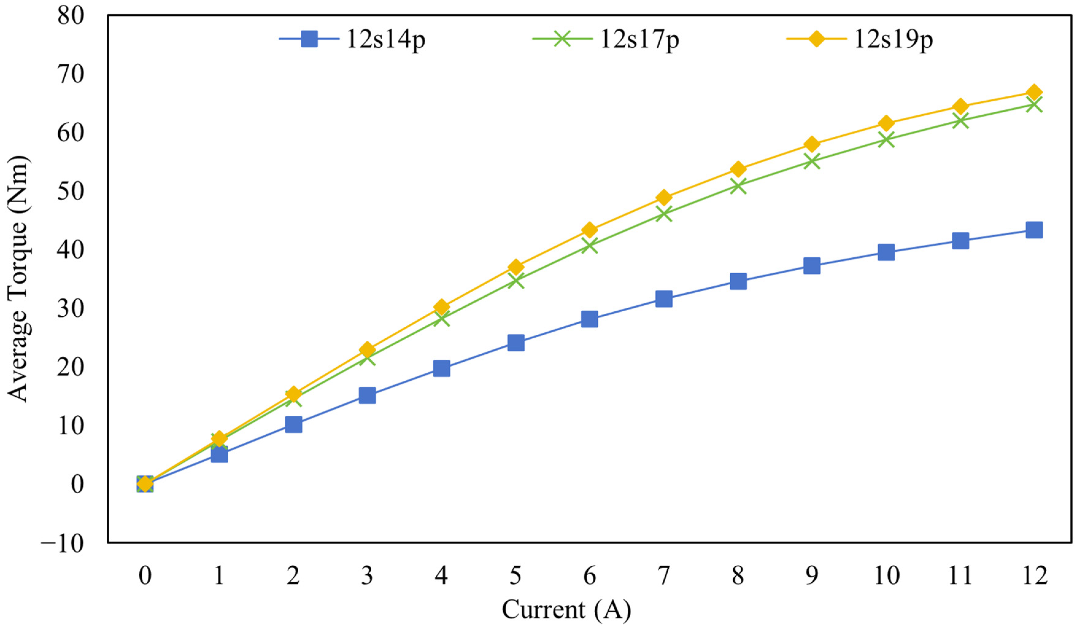
Figure 6 shows the torque-versus-current (T-I) characteristics of the three ST-BFMPMM variants (12s14p, 12s17p, 12s19p) at 400 rpm over a current range of 0–12 A. The 12s19p motor consistently delivers the highest torque among all motors across the entire current range. At the rated current of 6 A, the 12s19p motor produces 43.30 Nm, which is 6.54% higher than the 12s17p motor (40.64 Nm) and 54.29% higher than the 12s14p motor (28.06 Nm). Therefore, the 12s19p combination is selected as the optimal configuration for the proposed ST-BFMPMM.
For the torque ripple, the 12s14p variant presents an overall high torque ripple level. In comparison, both the 12s17p and 12s19p ST-BFMPMM can maintain relatively low torque ripple for most design samples. Nevertheless, the 12s19p scheme possesses more high-quality feasible solutions that achieve a better trade-off between high average torque and low torque ripple.
All three pole–slot combinations can generate abundant modulation harmonics due to the split-tooth stator design. However, the average torque and torque ripple are governed by two different factors: the rotor-to-stator pole–slot ratio and the least common multiple (LCM) between stator slot number and rotor pole number.
For average torque performance, the effectiveness of bidirectional field modulation depends strongly on the ratio of the rotor pole number to the stator slot number. For the 12s19p motor, this ratio is approximately 1.58; for the 12s17p motor, it is about 1.42; and for the 12s14p motor, it is about 1.17. A higher pole–slot ratio allows the split-tooth stator to produce a richer set of low-order permeance harmonics. These low-order harmonics interact more constructively with the rotor magnetomotive force (MMF), leading to stronger modulation and, consequently, higher torque density. Benefiting from larger pole–slot ratios, both 12s19p and 12s17p obtain enhanced field modulation effects and higher average torque. In contrast, the relatively low ratio of the 12s14p motor yields fewer low-order harmonics and weaker coupling between the stator and rotor fields, which limits its average torque output.
Apart from the average torque, the torque ripple discrepancy can be interpreted from the perspective of the least common multiple (LCM) of stator slots and rotor poles. The 12s14p configuration has the smallest LCM value among the three schemes. A smaller slot–pole LCM corresponds to lower cogging torque harmonic order, which results in higher cogging torque amplitude and further aggravates the overall torque ripple. In comparison, 12s17p and 12s19p possess much larger LCM values, and their cogging torque can be effectively suppressed. The 12s17p motor, with an intermediate pole–slot ratio, shows improved average torque performance but still falls short of the 12s19p design.
3.3. Torque Contribution
To further clarify the influence of the pole–slot combination on torque production, the working air-gap field harmonics of the 12s14p, 12s17p, 12s19p ST-BFMPMMs are systematically compared and summarized in
Table 2, including the harmonic spatial order, rotational normalized speed, rotation direction, winding factor, and torque contribution proportion of each dominant torque-effective harmonic.
A general rotating air-gap flux density harmonic can be expressed as follows:
By maintaining a constant field phase, the mechanical rotational speed of the harmonic is obtained as follows:
A positive value of represents forward rotation consistent with the armature rotating magnetic field, whereas a negative value denotes backward rotation.
From Equations (3) and (6), we can derive the rotational speeds of air-gap flux harmonics. For the stator PM field modulated by the rotor permeance, the signed spatial orders , and the rotational speeds are . For the rotor PM field modulated by the stator permeance, the spatial orders are , and the corresponding normalized speeds are . The original rotor PM harmonic of order rotates synchronously with the rotor, whereas the original stator PM harmonics are stationary.
Only the air-gap field harmonics that couple with the corresponding spatial harmonics of the three-phase armature-winding MMF, have nonzero winding factors, and rotate synchronously with the corresponding armature MMF harmonics can contribute to the steady average electromagnetic torque. The torque can be calculated using the Maxwell stress tensor method as follows:
where
is the average air-gap radius,
is the effective axial length of the motor,
denotes the spatial harmonic order,
and
are the amplitudes of the mth radial and tangential air-gap flux density harmonics, respectively, and
and
represent their corresponding initial phase angles. Each term in the summation corresponds to the torque component contributed by the
mth harmonic. By extracting the average value of each harmonic-related term, the torque contribution proportion of each working harmonic can be quantitatively obtained, as listed in
Table 2.
As shown in
Table 2, for each topology, only several specific harmonics can participate in torque production. For the 12s19p motor, the dominant torque-producing harmonics are 19th, 43rd and 55th order. The corresponding dominant harmonics for the 12s17p motor are 17th, 41st and 19th; for 12s14p, the dominant working harmonics are 14th, 38th and 26th. These observed effective harmonic orders are consistent with the harmonic
in Equation (10), which theoretically gives the harmonic orders capable of generating average torque under the magnetic field modulation principle. It can also be observed from
Table 2 that some modulation harmonics rotate backward and deliver negative torque contribution, such as the 19th harmonic in the 12s17p topology, which will counteract part of the total output torque.
Comparing the winding factor in
Table 2, both 12s19p and 12s17p topologies achieve a high winding factor of 0.9330 for their main working harmonics, which is significantly higher than the 0.5000 of the 12s14p topology. According to Equation (10), the winding factor
is in direct proportion to the torque contribution of each corresponding harmonic. Therefore, benefiting from the larger winding factor of primary working harmonic, 12s19p and 12s17p obtain higher main-harmonic torque contributions of 91.76% and 90.46%, respectively. In contrast, the low winding factor of 12s14p results in only 82.35% torque contribution from its fundamental working harmonic.
Nevertheless, there is still an obvious performance gap between 12s19p and 12s17p. Although they share identical winding factor, 12s17p excites a backward-rotating 19th-order modulation harmonic, bringing 2.06% negative torque. No comparable negative torque contribution is observed among the dominant harmonics of the 12s19p topology. As a result, 12s19p exhibits the best comprehensive torque performance among the three pole–slot schemes.
3.4. Final Design Parameters
Combining the multi-objective optimization results, torque characteristics, and harmonic torque contribution analysis of the three pole–slot configurations, the 12s19p topology is finally selected as the optimal scheme for the proposed ST-BFMPMM. Compared with the 12s14p and 12s17p counterparts, the 12s19p configuration delivers the highest average torque while maintaining low torque ripple. This superior performance benefits from its higher pole–slot ratio and larger least common multiple of slots and poles, together with fewer negative-torque components induced by backward-rotating harmonics.
4. Comparative Electromagnetic Performance Analysis
To validate the superiority of the proposed ST-BFMPMM with the 12s19p configuration, a comprehensive electromagnetic performance comparison is conducted between the 12s19p ST-BFMPMM and the baseline RFMPMM. The baseline motor has a conventional stator, without split teeth or stator slot PMs, and its rotor uses the same consequent-pole structure.
The pole–slot combination of the baseline RFMPMM is also selected before the formal comparison. As discussed in
Section 3.2, the 12s14p configuration has a smaller LCM and therefore produces higher torque ripple. Thus, the 12s17p and 12s19p RFMPMMs are selected as the candidate baseline motors. The two RFMPMMs are separately optimized using the same dimensional constraints, material properties, operating conditions, and optimization objectives. Six geometric parameters are involved in the optimization: rotor outer radius (
Rro), rotor tooth height (
hr), rotor tooth inner arc angle (
αri), rotor tooth outer arc angle (
αro), stator yoke thickness (
hsy), and slot width (
wss).
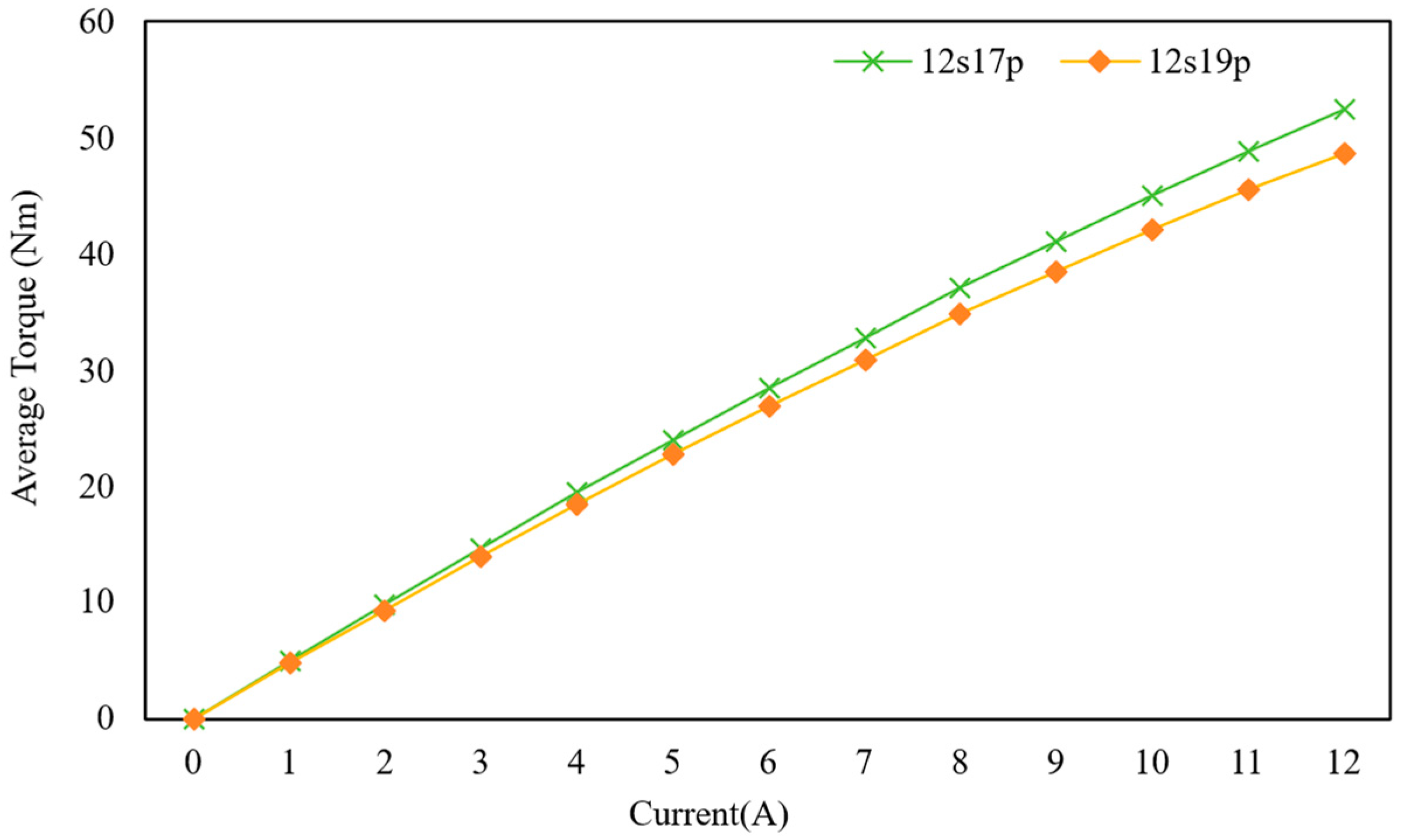
Figure 7 shows torque–current characteristics of the two optimized RFMPMMs at 400 rpm over a current range of 0–12 A. The 12s17p RFMPMM produces higher torque than the 12s19p RFMPMM at all loaded points. At the rated current of 6 A, the two motors produce 28.50 Nm and 26.88 Nm, respectively. Thus, the 12s17p RFMPMM produces about 6.0% higher rated torque than the 12s19p RFMPMM. Therefore, the 12s17p RFMPMM is selected as the more competitive baseline motor for the following comparison. This result also indicates that the use of the 19-pole combination alone does not improve the torque performance of the conventional RFMPMM.
Based on the above results, the optimized 12s17p RFMPMM is used as the baseline motor in the following comparison. Although the proposed motor and the baseline motor have different pole–slot combinations, the above comparison shows that the selected 12s17p RFMPMM performs better than the 12s19p RFMPMM. Therefore, the performance improvements reported below should be understood as the overall improvements of the two optimized motor designs, including the effects of both the motor topology and the pole–slot combination, rather than the isolated contribution of the proposed topology. Since the RFMPMM with best pole–slot combination is selected as a baseline, the comparison provides a conservative evaluation of the torque improvement.
The rated operating condition for the proposed 12s19p ST-BFMPMM and the 12s17p baseline motor is defined as a current of 6 A and a rotational speed of 400 rpm. Both motors share the same stator outer diameter, rotor inner diameter, air-gap length and effective stack length to ensure a fair comparison. The slot areas of the baseline RFMPMM and the proposed ST-BFMPMM are 103.158 mm
2 and 100.146 mm
2, respectively. Due to the same slot fill factor, their total copper areas are nearly identical. In addition, the turn in series per phase of both motors is 50 turns. Therefore, the armature copper area, winding excitation, and electrical loading of the two motors are appropriately comparable. The optimization variables for the proposed ST-BFMPMM have been described in
Section 3.1, and the final optimized key geometric parameters of the two motors are summarized in
Table 3. It is worth noting that the proposed ST-BFMPMM achieves prominent torque density improvement under a much lower PM consumption. As listed in
Table 3, the total PM area of the baseline motor reaches 738.74 mm
2, while the PM usage of the proposed motor is only 447.76 mm
2, which is 39.4% less than the baseline counterpart.
All electromagnetic performance simulations are conducted using two-dimensional time-stepping finite element analysis in JMAG-Designer. Finite element models are established for the proposed ST-BFMPMM and the baseline RFMPMM, respectively. The ST-BFMPMM model contains 32,666 finite elements and 17,944 nodes, whereas the RFMPMM model contains 51,723 finite elements and 27,466 nodes. Local mesh refinement is applied to the air gap and PM regions to adequately resolve the air-gap magnetic field harmonics and torque waveforms. The stator and the rotor are modeled using 35CS300 laminated electrical steel. Its nonlinear B–H magnetization curve and specific core loss data are obtained directly from the built-in JMAG material library without artificial modification. The magnetic vector potential on the outer boundary of the computational domain is set to zero, corresponding to a flux-parallel boundary condition. Because the two-dimensional model does not geometrically represent the end-winding regions, the leakage inductance of the stator end connections is not included. This simplification has little influence on the current-controlled torque comparison at the rated low-speed operating point, but it may affect the predicted terminal voltage, power factor, and voltage-limited high-speed performance. This limitation should be considered when interpreting the high-speed simulation results.
4.1. No-Load Performance Comparison
No-load performance is a key indicator to evaluate the magnetic circuit design and harmonic characteristics of PM motors. This part analyzes the air-gap flux density, no-load back-EMF, and cogging torque of the two motors in detail.
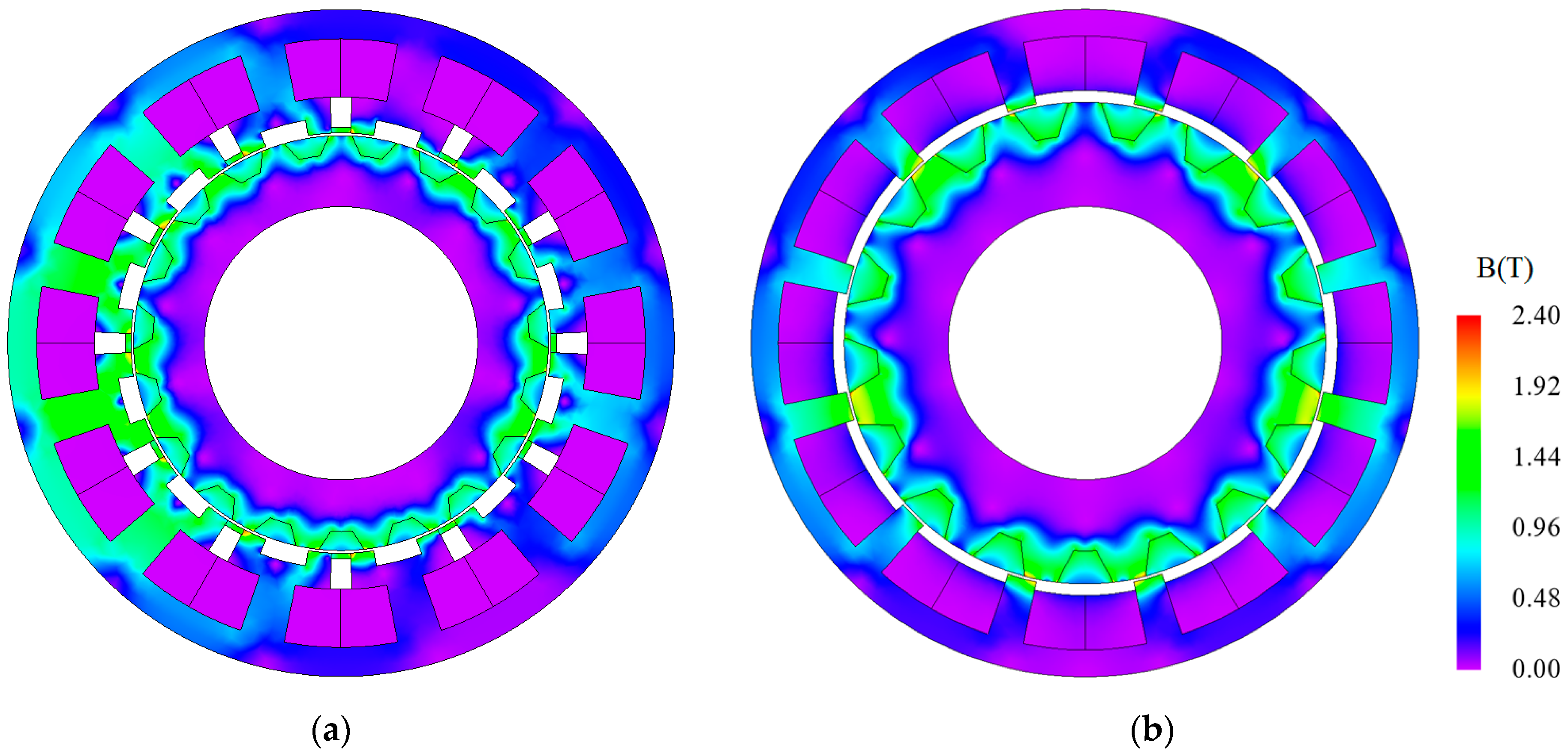
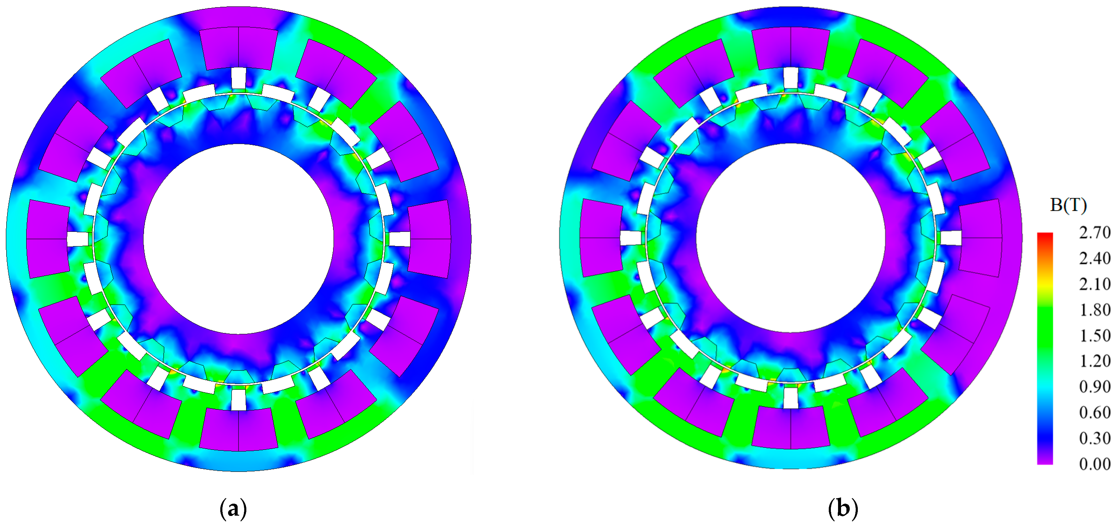
Figure 8 compares the no-load magnetic flux density distribution of the proposed ST-BFMPMM and baseline RFMPMM under identical rotor position and unified color scale (0–2.4 T). The proposed ST-BFMPMM exhibits significantly larger high-magnetic-density regions in stator teeth, which shows improved utilization of PMs and higher back-EMF amplitude.
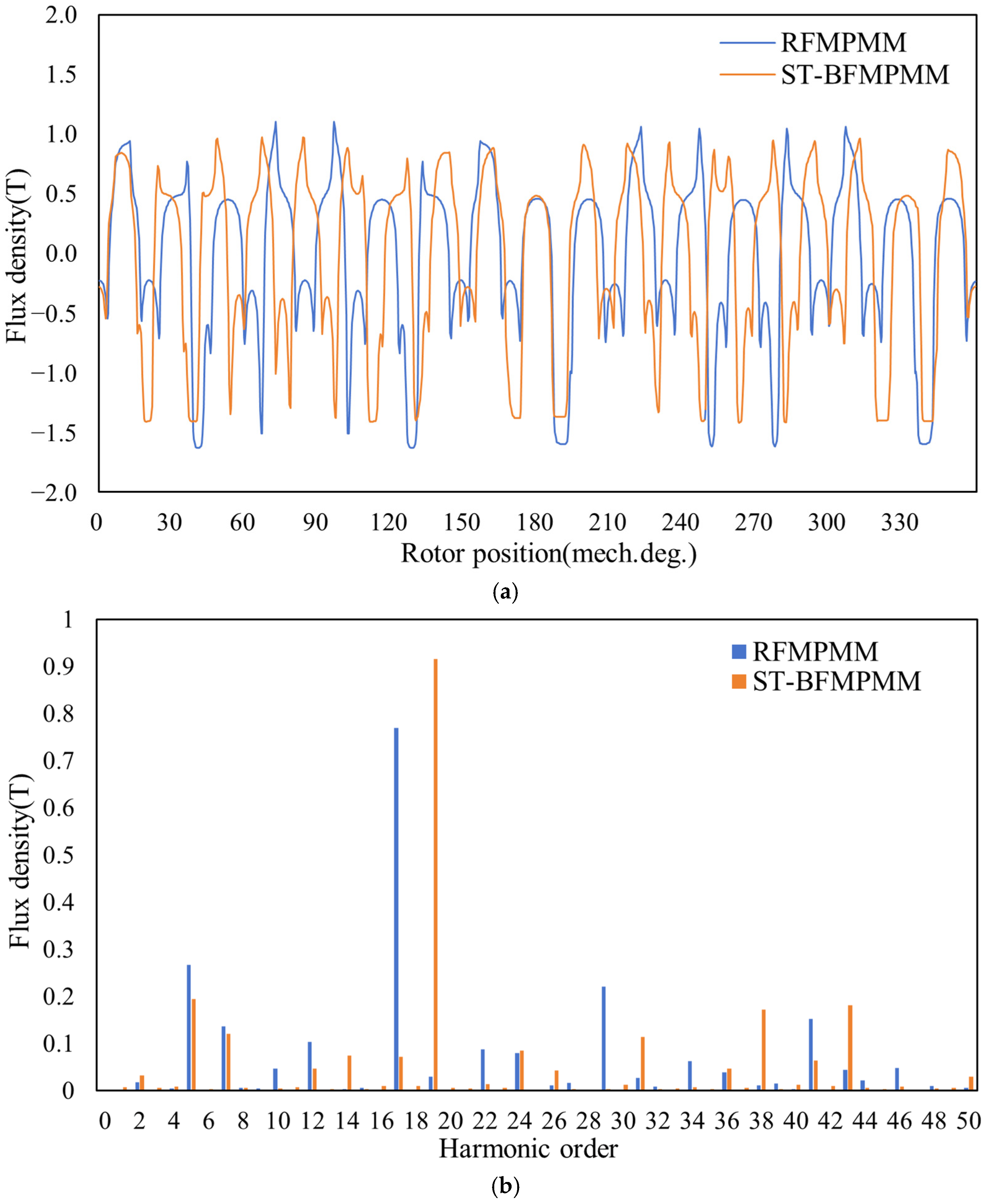
The radial air-gap flux density distributions along the air-gap circumference under no-load conditions are shown in
Figure 9a. The baseline RFMPMM exhibits a slightly higher peak flux density compared with the proposed 12s19p ST-BFMPMM. This is mainly because the baseline motor has a larger effective air-gap area due to the absence of stator PMs and split-tooth geometry, which reduces local saturation. In contrast, the proposed motor has additional stator slot PMs and split teeth that create more local flux barriers, resulting in a slightly lower peak value.
Figure 9b shows the corresponding harmonic spectra, revealing that the proposed ST-BFMPMM significantly enriches specific working harmonics. For instance, compared to the baseline motor, the amplitudes of the 19th, 31st, 38th and 43rd harmonics of the proposed ST-BFMPMM are substantially enhanced, while the 5th and 7th harmonics remain competitive.
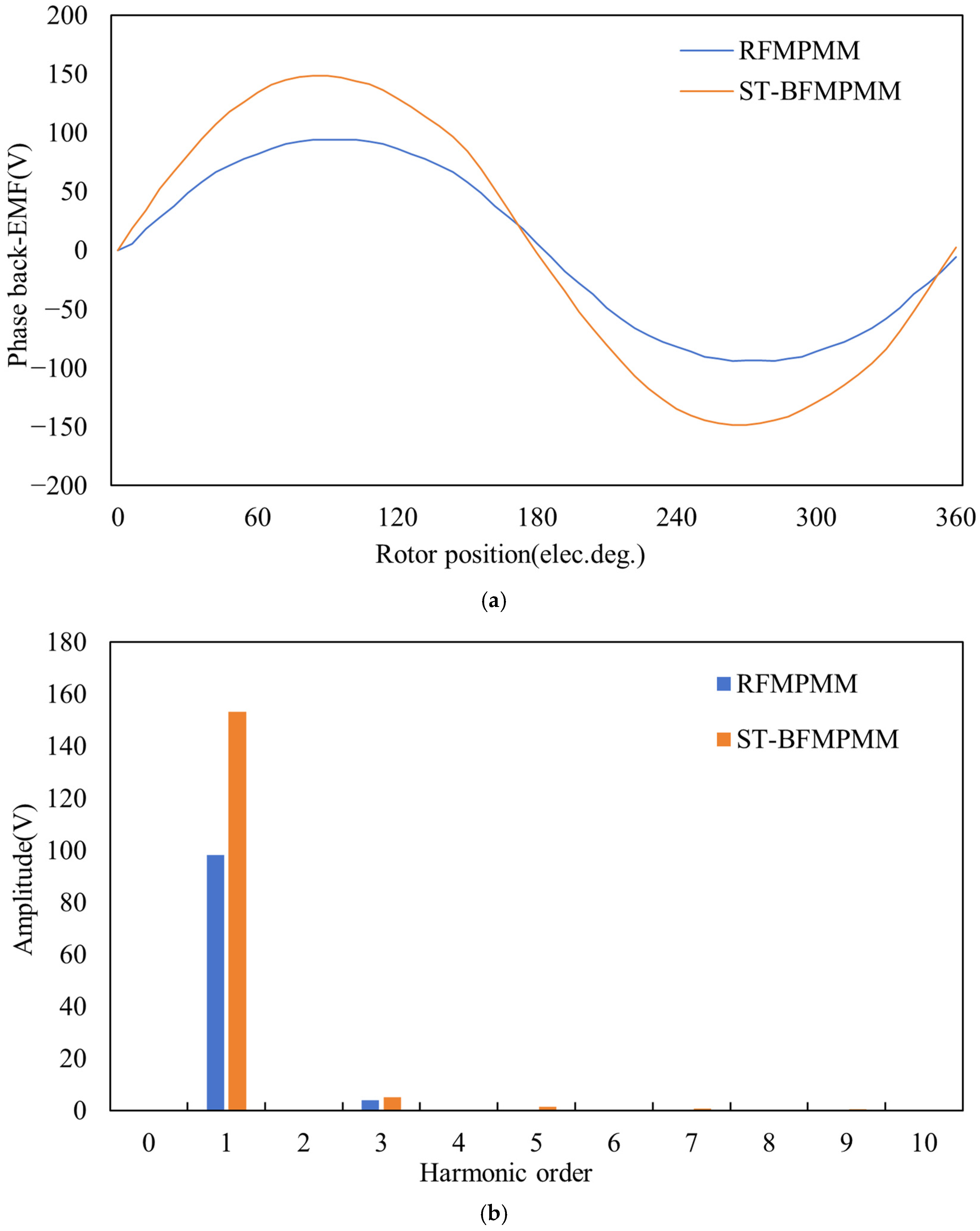
The no-load back-EMF waveforms of the RFMPMM and the proposed ST-BFMPMM at the rated speed of 400 rpm are shown in
Figure 10. The ST-BFMPMM generates a substantially higher back-EMF amplitude throughout the electrical cycle. The fundamental amplitude obtained from Fourier analysis is approximately 153.27 V for the ST-BFMPMM, compared with 98.33 V for the RFMPMM, representing an increase of about 55.9%. Both waveforms remain nearly sinusoidal, with low harmonic distortion. The 5th and 7th harmonics of the ST-BFMPMM (1.52 V and 0.81 V) are higher than those of the RFMPMM (0.18 V and 0.42 V), while the 3rd harmonic (5.21 V vs. 3.91 V) is also slightly increased. Nevertheless, the overall harmonic content is acceptable, and the significant enhancement of the fundamental component directly contributes to the improved torque density of the proposed ST-BFMPMM.
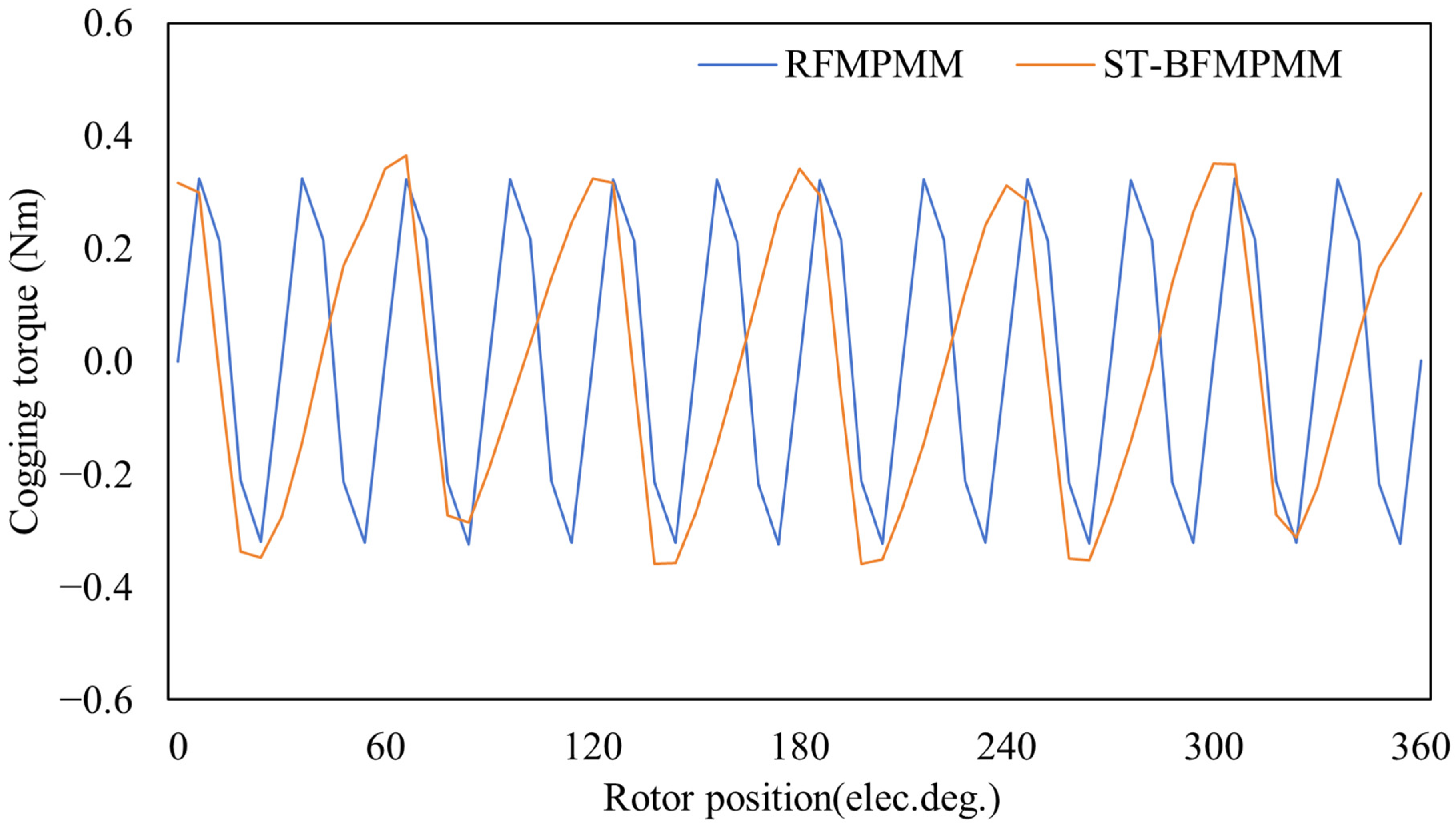
Figure 11 shows the cogging torque waveforms of the two motors plotted against electrical angle. It can be observed that the proposed ST-BFMPMM exhibits a peak-to-peak cogging torque of approximately 0.72 Nm, while the RFMPMM shows a value of about 0.65 Nm. The slightly increased cogging torque in the proposed motor is attributed to the additional stator slot PMs and split-tooth structure, which introduce more flux variations in the air gap. However, the cogging torque remains relatively small compared to the rated torque of 43.30 Nm, accounting for only about 1.7% of the rated value.
4.2. Load Performance Comparison
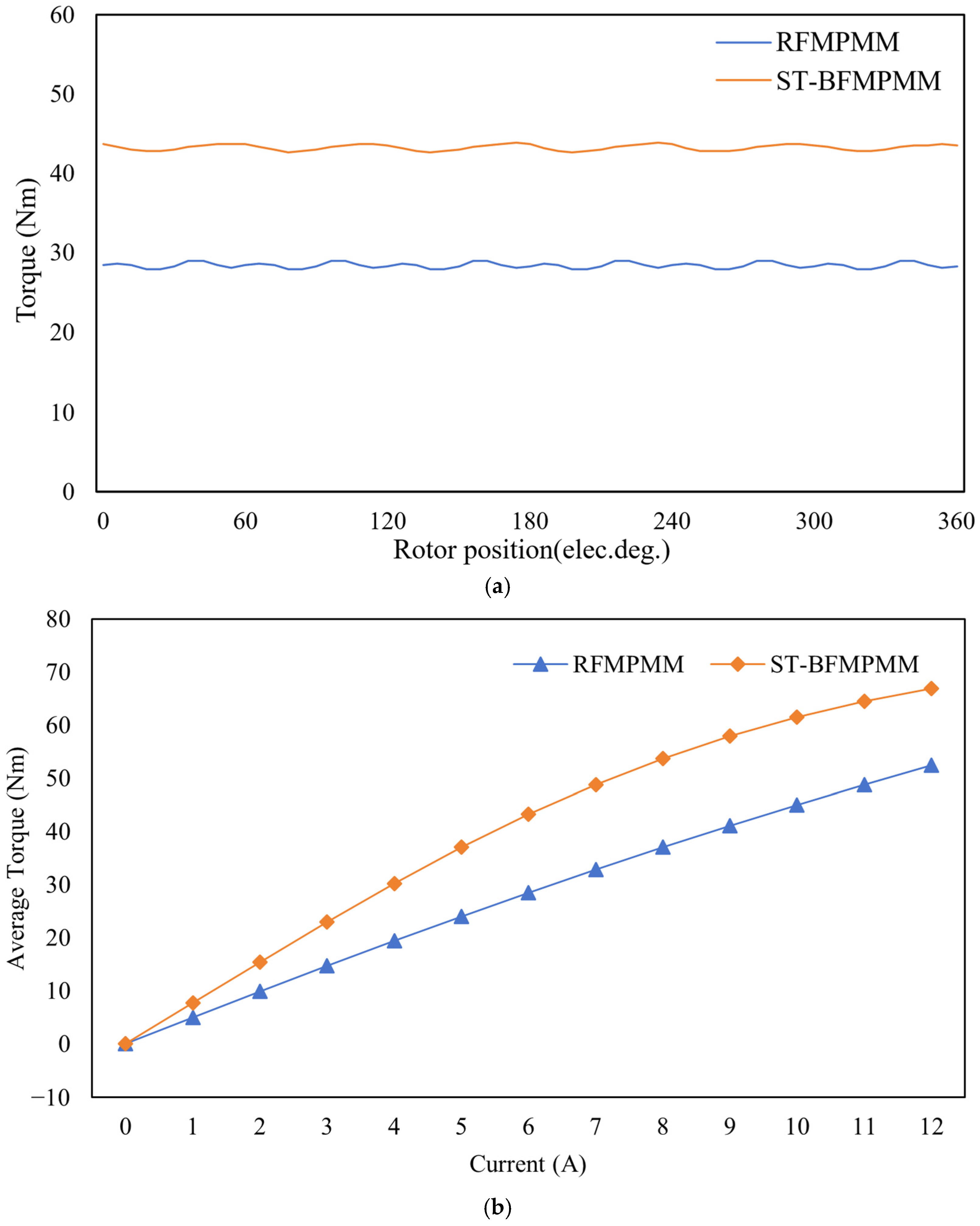
Figure 12a shows the electromagnetic torque waveforms of the two motors under rated operating conditions (6 A, 400 rpm). The proposed ST-BFMPMM achieves an average torque of 43.30 Nm, which is 51.93% higher than that of the RFMPMM (28.50 Nm). More importantly, the proposed motor exhibits lower torque ripple, with a value of 2.57% compared to 3.94% for the RFMPMM, a reduction of approximately 34.77%. This confirms that the proposed ST-BFMPMM effectively suppresses torque ripple under load, despite a slight increase in cogging torque under no-load conditions.
Figure 12b presents the torque versus current (T-I) characteristics of both motors over a current range of 0–12 A at a constant speed of 400 rpm. The proposed ST-BFMPMM consistently delivers higher torque than the RFMPMM across the entire range. At 12 A, the proposed motor achieves 66.87 Nm, while the RFMPMM provides 52.44 Nm, representing a 27.51% increase. Moreover, in the linear region, the torque–current slope of the ST-BFMPMM is significantly larger than that of the RFMPMM, indicating a more effective conversion of current into torque. This superior torque density is attributed to the split-tooth stator, which enriches the air-gap permeance harmonics and amplifies the torque-contributing components, as well as the bidirectional field modulation effect that becomes more effective under load. The results confirm that the proposed ST-BFMPMM offers significantly higher torque output across the entire current range, making it an excellent candidate for high-torque direct-drive applications in energy systems.
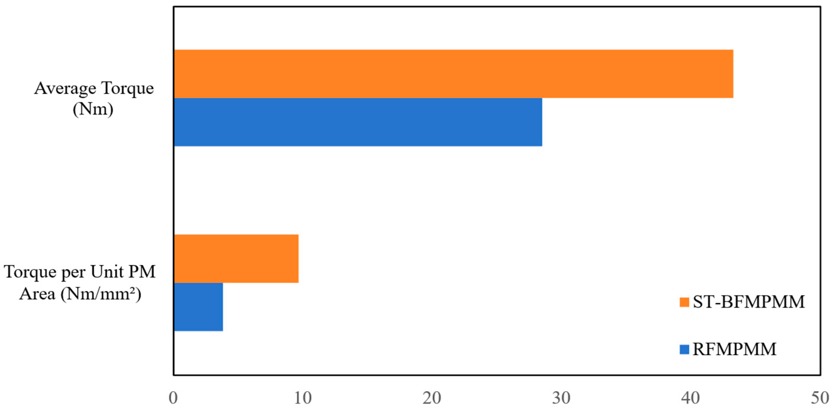
Figure 13 further quantitatively compares the torque capacity and PM utilization efficiency of the two motors. To solve the problem of huge numerical gap between average torque and torque per unit PM area, the bar height of torque per unit PM area is magnified by 10 times in the histogram for clearer observation.
Under rated operation, the average electromagnetic torque of the proposed ST-BFMPMM reaches 43.30 Nm with a PM area of 447.76 mm2, yielding an original torque output per unit PM area of 0.0967 Nm/mm2. In contrast, the baseline RFMPMM only outputs 28.50 Nm, consuming a much larger PM area of 738.74 mm2, and its torque per unit PM area is merely 0.0386 Nm/mm2.
The torque per unit PM area of ST-BFMPMM is 2.51 times that of RFMPMM, which fully demonstrates the prominent advantage in rare-earth material utilization of the proposed ST-BFMPMM. Benefiting from enhanced air-gap flux density and optimized magnetic field modulation effect, the proposed motor realizes higher average torque output with substantially reduced PM consumption. This characteristic effectively cuts down the manufacturing cost of the motor and improves the material utilization rate of PMs, which is of great significance for the design of low-cost, high-torque, energy-saving drive motors.
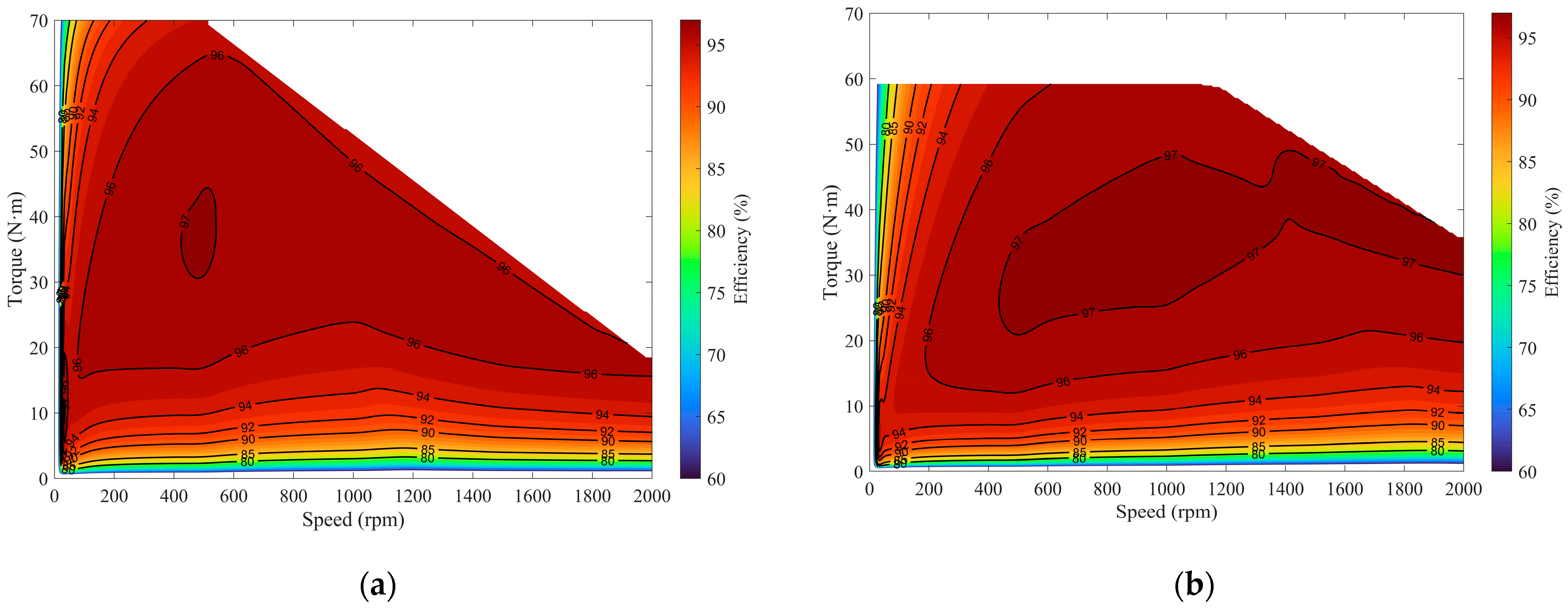
Figure 14 presents the efficiency maps of the proposed ST-BFMPMM and the baseline RFMPMM over their respective operating ranges. Both motors exhibit broad high-efficiency regions in the main low-speed operating range. At 400 rpm and a phase current of 6 A, the proposed ST-BFMPMM operates at 43.30 Nm with an efficiency of 96.88%, whereas the baseline RFMPMM operates at 28.50 Nm with an efficiency of 96.87%. Therefore, the proposed motor increases the rated torque by 51.93% and reduces PM consumption by 39.4%, while maintaining essentially the same efficiency.
The efficiency maps are generated using transient FEA. The winding copper loss is determined from the RMS phase current and the phase resistance at the specified winding temperature. The losses of the stator and the rotor are calculated using the time-varying local flux density waveforms and the loss characteristics of the selected electrical steel, including the hysteresis and eddy current components. Mechanical loss is represented by a linear speed-dependent model with a coefficient of 15 W/krpm, corresponding to 6 W at the rated speed of 400 rpm. The winding and PM temperatures are fixed at 20 °C, and thermal–electromagnetic coupling is not considered. PM eddy current loss is not included in the present two-dimensional model. Therefore, the reported efficiency may be slightly overestimated.
Table 4 compares the loss components of the two motors at their rated operating points. The winding copper losses of the proposed ST-BFMPMM and the baseline RFMPMM are nearly identical, at 18.07 W and 18.00 W, respectively. Owing to the richer magnetic field harmonics introduced by the split-tooth bidirectional field modulation structure, the stator core loss of the proposed motor increases to 29.05 W, compared with 8.49 W for the baseline motor. In contrast, its rotor loss decreases slightly, from 6.05 W to 5.35 W. Including the mechanical loss of 6 W, the total calculated losses of the proposed and baseline motors are 58.47 W and 38.54 W, respectively. Although the proposed motor has a higher absolute total loss, its mechanical output power is also 51.93% higher. Consequently, the two motors achieve almost identical rated-point efficiencies of 96.88% and 96.87%. Overall, the proposed ST-BFMPMM achieves a favorable balance among higher torque capability, improved PM utilization, and comparable efficiency, despite the additional stator core loss caused by its richer magnetic field harmonics.
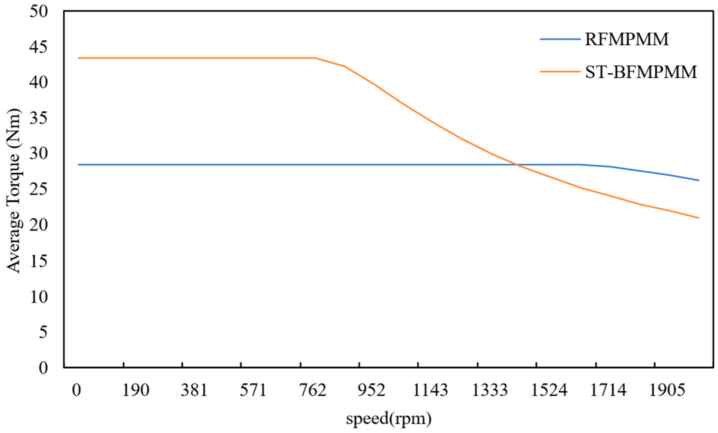
Figure 15 shows the average torque versus speed characteristics of the proposed ST-BFMPMM and the baseline RFMPMM. In the low-speed region, from 0 to 761 rpm, both motors operate in a stable constant torque region. The torque of RFMPMM remains steady at approximately 28.5 Nm, while the ST-BFMPMM outputs a constant torque of 43.3 Nm, which fully reflects the superior torque density of the proposed topology for low-speed operating conditions.
When the speed exceeds 761 rpm, the torque of ST-BFMPMM begins to rapidly decrease. In contrast, RFMPMM maintains its constant torque performance up to 1620 rpm and only shows a mild torque drop at higher speeds. At the maximum speed of 2000 rpm, the average torque of RFMPMM is 26.27 Nm, whereas the torque of ST-BFMPMM decreases to 21.05 Nm.
The obvious difference in torque–speed characteristics is mainly attributed to the abundant flux harmonics generated by the split-tooth and bidirectional field modulation structure, which result in a higher fundamental back-EMF in the proposed ST-BFMPMM. As the rotational speed increases, the back-EMF rises and progressively reduces the available voltage margin. Consequently, the proposed motor reaches the voltage limit at approximately 761 rpm, beyond which the torque-producing current can no longer be maintained, leading to a rapid reduction in output torque. Nevertheless, considering that the proposed motor is designed for low-speed, high-torque, direct-drive equipment such as wind turbines and heavy agricultural machinery, its excellent constant torque performance in the target operating range can effectively meet the practical application requirements.
6. Conclusions
This paper proposes a compact single-stator, single-rotor, split-tooth bidirectional field modulation permanent magnet motor (ST-BFMPMM) for low-speed, high-torque, direct-drive applications. The split-tooth stator and consequent-pole rotor enable mutual modulation of the stator and rotor PM fields, thereby enhancing torque-producing harmonics. Among the optimized 12s14p, 12s17p, and 12s19p configurations, the 12s19p design achieves the best overall performance. Compared with the conventional 12s17p RFMPMM, its rated torque increases from 28.50 to 43.30 Nm, while PM consumption decreases by 39.4% and torque ripple decreases from 3.94% to 2.57%. Its fundamental back-EMF is increased by 55.9%, and its torque output per unit PM area is 2.51 times that of the baseline motor. Meanwhile, the two motors have nearly identical calculated rated efficiencies of 96.88% and 96.87%. Under 150% overload, magnetic saturation remains confined to small tooth-root regions. Under the combined conditions of 150% rated current, a 90° current advance angle, and a PM temperature of 120 °C, only negligible pole-tip regions exhibit slight demagnetization. Nevertheless, the increased stator core loss remains the main limitation. Future work will focus on harmonic suppression, PM segmentation, flux barrier optimization, and experimental validation to reduce losses and extend the high-efficiency operating range.