Article

Self-Aligning Torque Energy Recovery and Bus-Voltage Stabilization in Steer-by-Wire Systems for New Energy Vehicles

School of Intelligent Transportation and Vehicle, Qingdao University of Technology, Qingdao 266520, China
*
Author to whom correspondence should be addressed.
Actuators 2026, 15(7), 397; https://doi.org/10.3390/act15070397
Submission received: 21 May 2026 / Revised: 15 June 2026 / Accepted: 24 June 2026 / Published: 14 July 2026
(This article belongs to the Special Issue Analysis and Design of Linear/Nonlinear Control System—2nd Edition)

Abstract

This study proposes an integrated self-aligning-torque energy recovery and DC-bus voltage stabilization strategy for a permanent-magnet synchronous motor (PMSM)-driven steer-by-wire system in new energy vehicles. During the front-wheel return-to-center process, self-aligning torque may provide excess mechanical energy to the steering actuator. Instead of dissipating this energy through a braking resistor, the proposed strategy converts part of the self-aligning-torque-induced mechanical energy into electrical energy and feeds it back to the low-voltage DC bus. To avoid ambiguity in the operating-mode description, this paper distinguishes the standard PMSM torque–speed quadrants from the mechanical stages of the steering process. Regenerative operation is defined according to the condition ( T e ω m < 0 ), corresponding to the second or fourth quadrant of the PMSM torque–speed plane, whereas the return-to-center regenerative stage refers to the self-aligning-torque-dominated stage of the steer-by-wire motion. Based on this definition, an electromechanical energy-flow model is established to describe the transfer path from self-aligning torque to the PMSM and then to the DC bus. Considering that regenerative energy injection may cause DC-bus voltage fluctuation or braking-resistor activation, a single-loop bus-voltage stabilization method based on active disturbance rejection control is developed. A third-order linear extended state observer is adopted to estimate the lumped disturbance caused by self-aligning-torque variation, current coupling, load variation, parameter uncertainty, and inverter loss. The observer bandwidth, controller gains, current limitation, and overvoltage protection mechanisms are further discussed to improve the practical implementability of the proposed control strategy. In addition, an energy-accounting method is introduced to distinguish total steering energy consumption, available self-aligning-torque mechanical energy, gross recovered electrical energy, system losses, net recovered energy, and recovery efficiency. Simulation and experimental results show that the proposed strategy can suppress DC-bus voltage rise, reduce braking-resistor energy dissipation, and achieve measurable steering-actuator-level energy recovery during repeated return-to-center maneuvers. The results verify the feasibility of using self-aligning-torque-induced regenerative energy in PMSM-driven steer-by-wire systems, while the actual vehicle-level energy benefit depends on the driving cycle, low-voltage load demand, battery charging acceptance, and converter efficiency.

1. Introduction

In new energy vehicles equipped with steer-by-wire SbW systems, self-aligning torque SAT plays an important role during the front-wheel return-to-center process. When a nonzero angle exists between the wheel heading and the vehicle travel direction, SAT is generated and tends to restore the front wheels to the straight-ahead position, with its magnitude generally increasing with steering deviation [1,2]. In SbW systems, the return motion of the front wheels can be actively regulated to improve steering controllability and motion stability. However, during constant-speed return-to-center operation, the excess mechanical energy provided by SAT is usually dissipated through the braking resistor of the permanent-magnet synchronous motor PMSM drive system to prevent DC-bus overvoltage. Although this method ensures safe operation, it also causes avoidable energy loss in the form of heat. Therefore, this study develops an energy-recovery strategy to capture and utilize the excess energy induced by SAT, thereby improving the energy efficiency of new energy vehicle SbW systems.
Regarding energy-saving strategies for steer-by-wire SbW systems in new energy vehicles, previous studies have mainly focused on structural optimization, parameter matching, and controller design. Cui [3] established a multi-objective optimization model for an electro-hydraulic active steering system and applied a multi-objective genetic algorithm to reduce energy consumption. Zhao [4] simultaneously considered steering energy consumption, road-feel performance, and steering-wheel return error, and proposed an improved competitive multi-objective particle swarm optimization algorithm to enhance convergence and optimization performance. Zou [5] developed a minimum-power-consumption model based on the required torque, steering-wheel speed, and motor efficiency map, and further optimized the torque-distribution coefficient using an adaptive particle swarm optimization algorithm. Abu Hanifah [6,7] optimized the PID controller parameters of an electric power steering system using particle swarm optimization and ant colony optimization to reduce operating current. In addition, Zhao et al. [8] proposed a novel steering-system configuration with two variable-ratio rotary dampers and one rotary spring, thereby improving steering performance while reducing motor energy consumption under different steering modes. Overall, these studies demonstrate that structural refinement and controller optimization can effectively reduce steering energy consumption. However, most existing methods focus on energy saving from the perspectives of parameter tuning and mechanism design, whereas the recovery and utilization of regenerative energy during the front-wheel return-to-center process—a critical approach for enhancing the overall energy efficiency of new energy vehicles—remain insufficiently explored. It should be noted that the feasibility of using self-aligning torque as an energy source has been previously investigated. Morton et al. demonstrated that self-aligning torque can be regarded as a recoverable mechanical energy source in steering systems. This provides an important basis for SAT-related energy recovery. However, the present study focuses on a different problem: how the SAT-induced mechanical energy can be converted by a PMSM-driven steer-by-wire actuator, injected into a low-voltage DC bus, and regulated without excessive bus-voltage rise or braking-resistor dissipation. Therefore, the novelty of this work does not lie only in identifying SAT as an energy source, but in developing an integrated SAT–PMSM–DC-bus energy-flow model and a bus-voltage stabilization strategy for PMSM-driven steer-by-wire systems.
Relevant progress has also been reported in PMSM-based energy management and hybrid energy storage systems. Hu [9] realized power management in a hybrid energy storage system based on dual three-phase in-wheel motors, where two sets of windings were connected to an ultracapacitor and a battery through separate inverters. A dedicated control scheme was proposed to regulate unbalanced winding power distribution and suppress motor harmonic currents under unbalanced operating conditions, and both simulation and experimental results demonstrated good dynamic response and smooth mode transition. Mese [10] investigated the operating modes and converter selection of a PMSM for hybrid electric vehicles, showing that the machine could operate in motor mode, generator mode, and synchronous generator mode. Moreover, Hu [11] proposed a torque-distribution control strategy for multiphase motors in hybrid energy storage systems by introducing winding decoupling compensation, flux observation, and parameter identification to achieve coordinated power allocation. Although these studies provide useful references for regenerative energy utilization and coordinated energy management, they mainly focus on hybrid storage architectures and multiphase drive systems, whereas the recovery and direct utilization of self-aligning-torque-induced regenerative energy in steer-by-wire systems remain insufficiently explored.
To recover the excess energy induced by self-aligning torque during steering, this study develops a PMSM-driven steer-by-wire system for new energy vehicles. The PMSM is adopted as the steering actuator because of its high torque density, fast response, and compatibility with low-voltage vehicular power systems. By exploiting the regenerative operating characteristic of the PMSM during the return-to-center process, the excess mechanical energy provided by self-aligning torque can be converted into electrical energy. However, road disturbances, operating-condition variations, and unmodeled dynamics may cause significant DC-bus voltage fluctuation, thereby reducing the stability of energy recovery and storage. In addition, harmonic currents generated during PMSM operation may introduce extra losses and further lower recovery efficiency. To address these issues, a return-to-center regenerative bus-voltage stabilization strategy based on active disturbance rejection control is proposed to improve voltage regulation and enhance regenerative energy utilization.
Further related work has been reported on DC-bus voltage regulation, disturbance rejection, and regenerative energy utilization in electrified drive systems. Hu [12] proposed a fault-tolerant control strategy for a dual three-phase permanent-magnet synchronous generator system to suppress both second-harmonic torque ripple and DC-bus voltage ripple under rectifier fault conditions. Wang et al. [13] introduced an active disturbance rejection control scheme for DC-bus voltage regulation in onboard starter/generator systems, where a second-order extended state observer was employed to generate the torque reference, and experimental results demonstrated faster and more robust regulation than conventional PI-based control. Hu [14] further proposed an effective method for suppressing second-harmonic torque ripple in impedance-asymmetric permanent-magnet synchronous generator systems by means of average-power control. In addition, Kenné [15] developed a nonlinear adaptive excitation controller to improve the transient stability and voltage-regulation performance of synchronous generators under uncertain operating conditions, while Ali [16] proposed a disturbance-observer-based control method to compensate for system nonlinearity and parameter variations caused by temperature and aging effects. Beyond electrical machines, Qu [17] designed an electro-hydraulic drive architecture with four-quadrant operation and energy-recovery capability, Long [18] investigated a suspension-drive mechanism capable of both vibration suppression and energy harvesting, and Xu [19] proposed regenerative energy absorption methods for different starter/generator systems to prevent excessive DC-link voltage rise during braking. Moreover, Wang et al. [20] reviewed the applications of motors/generators in electrified vehicle chassis systems, showing that energy-regenerative electric actuators are becoming increasingly important in future intelligent and lightweight vehicle platforms. These studies provide useful references for DC-bus stabilization, disturbance compensation, and regenerative energy utilization. However, the direct recovery and regulation of self-aligning-torque-induced energy in PMSM-driven steer-by-wire systems for new energy vehicles remain insufficiently explored.
In view of the above research gap, this study develops an integrated energy-recovery and bus-voltage stabilization strategy for a PMSM-driven steer-by-wire system in new energy vehicles. The main contributions of this work are summarized as follows.
(1)
A SAT–PMSM–DC-bus energy-flow framework is established for the steer-by-wire return-to-center process. The complete steering maneuver is divided into steering acceleration, steering deceleration, return-to-center regeneration, and assisted return stages. The regenerative stage is analyzed using the standard PMSM torque–speed sign convention, where regenerative operation occurs when the electromagnetic torque and motor speed have opposite signs. This framework clarifies the mechanical origin of recoverable energy and its transfer path from self-aligning torque to the PMSM, inverter, DC bus, and braking branch.
(2)
A practical energy-balance model is developed for SAT-induced regenerative operation. Different from the ideal assumption that all excess mechanical energy is stored in the DC-link capacitor, the revised model considers DC-link energy storage, battery-side absorption, PMSM copper loss, iron loss, inverter loss, mechanical friction loss, DC-link capacitor loss, and braking-resistor dissipation. Based on this model, gross recovered energy, net recovered energy, recovery efficiency, and steering-system-level energy-saving ratio can be quantitatively evaluated.
(3)
A bus-voltage stabilization strategy based on linear active disturbance rejection control is proposed for regenerative return-to-center operation. The DC-bus voltage loop and the q-axis voltage generation are formulated in a unified control framework. A third-order linear extended state observer is used to estimate the lumped disturbance caused by SAT power injection, PMSM parameter uncertainty, current coupling, load variation, and inverter loss. The observer and controller parameters are tuned using a bandwidth-based criterion, and current and voltage saturation mechanisms are included to improve implementation safety.
(4)
Simulation and experimental tests are carried out to validate the proposed method. The results show that the proposed strategy can suppress DC-bus voltage fluctuation, reduce unnecessary braking-resistor activation, and recover part of the steering energy during repeated return-to-center maneuvers. These results verify the feasibility of the proposed integrated energy-recovery and voltage-stabilization strategy for low-voltage steer-by-wire systems in new energy vehicles.
The remainder of this paper is organized as follows. Section 2 establishes the vehicle, steering, PMSM, and energy-flow models, and clarifies the sign convention of regenerative operation during the return-to-center process. Section 3 presents the proposed LESO-based ADRC bus-voltage stabilization strategy, including the extended-state formulation, observer design, stability analysis, and parameter-tuning criterion. Section 4 provides the simulation and experimental validation, including regenerative bus-voltage regulation, braking-resistor activation analysis, long-duration cyclic energy recovery, and energy-accounting results. Section 5 concludes the paper and discusses model limitations and future work.

2. Steer-by-Wire Model with Energy Recovery for a New Energy Vehicle

2.1. Vehicle Model of the New Energy Vehicle Steer-by-Wire System

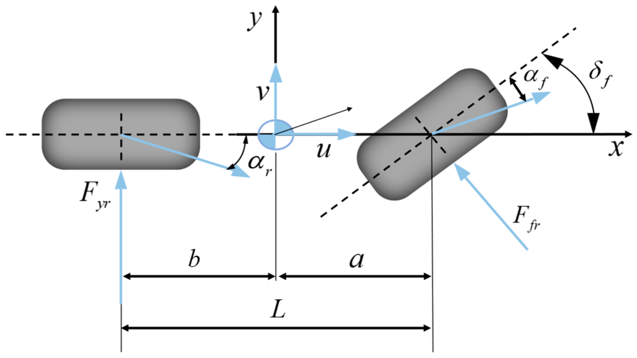
To describe the steering dynamics of the new energy vehicle, a bicycle model is adopted, in which the left and right wheels are equivalently lumped at the centers of the front and rear axles, as shown in Figure 1. The model captures the lateral and yaw motions of the vehicle while neglecting roll motion, which is appropriate for the present analysis of steer-by-wire dynamics and regenerative energy utilization during the front-wheel return-to-center process. The corresponding linearized dynamic equations are given as follows:
m v β ˙ + 1 v m v 2 + C f l f C r l r r + C f + C r β C f δ f = 0
I r ˙ + 1 v C f l f 2 + C r l r 2 r C r l r C f l f β C f l f δ f = 0
where β is side slip angle between the vehicle center and the velocity at the center of CG; r is yaw rate with respect to an inertial coordinate system; δ f is front steering angle; C r and C f are cornering stiffness for the rear (front) wheel; l r and l f are distance from the center of gravity to the rear (front) axis, wheel base; m is vehicle mass; I is moment of inertia with respect to vertical axis; v is vehicle longitudinal velocity which we assume always greater than zero. Rewriting Equations (1) and (2) into state space format, we have:
β ˙ r ˙ = a 11 a 12 a 21 a 22 β r + b 1 b 2 δ f
where a 11 = C f + C r m v ; a 12 = 1 C f l f C r l r m v 2 ; a 21 = C f l f C r l r I ; a 22 = C f l f 2 + C r l r 2 I v ; b 1 = C f m v ; b 2 = C f l f I .
In this study, an asymmetric permanent-magnet synchronous motor PMSM is adopted as the steering actuator of the steer-by-wire SbW system for a new energy vehicle. The corresponding steering dynamic model can be written as follows:
J e q δ ¨ f + B e q δ ˙ f + τ f + τ a + τ d = κ τ m
where J e q and B e q are the inertia and damping of the steering system; δ f is the steering angle; τ f is the coulomb friction; τ a is the self-aligning torque; τ d is the unmodelled dynamics and external disturbances; κ is the transmission coefficient; τ m 1 is the electromagnetic torque.
The self-aligning torque generated by the tire pneumatic trail can be expressed as follows:
M z v = m v 2 b L 2 + m k 2 b k 1 a k 1 k 2 v 2 ξ 1 + ξ 2 δ f
The restoring torque generated by the kingpin inclination and kingpin offset is independent of vehicle speed, and can be expressed as follows:
M A = Q D 2 sin 2 β 1 sin δ f
where M z v is the correction torque generated by the tire drag distance; m , v , a , b , L , k 1 , k 2 , ξ 1 , ξ 2 , δ f are the total vehicle weight, vehicle speed, distance from the center of mass to the front and rear wheels, wheelbase of the front and rear wheels, lateral stiffness of the front and rear wheels, pneumatic tire drag distance, rear tilt drag distance, and front-wheel steering angle, respectively; Q , D , β 1 are wheel load, kingpin displacement, and kingpin inclination angle.
If the current wheel angle δ f is small, sin δ f δ f then Equation (6) can be expressed as:
M A = Q D 2 sin 2 β 1 δ f
The total return torque of the tire is:
M h = M z v + M A
In actual driving conditions, the interaction between the tire and the ground also generates friction torque, which can be expressed as:
T f = F ω sin δ f
where F ω is a constant related to the damping coefficient, moment of inertia, and axle load.

Model Assumptions and Applicability of the 2-DOF Vehicle Model

The 2-DOF bicycle model used in this study is mainly introduced to describe the dominant lateral and yaw dynamics associated with the front-wheel return-to-center process. It is not intended to replace a high-fidelity full-vehicle model under extreme handling conditions. The proposed SAT energy-recovery mechanism is mainly investigated under low- to medium-speed steering and return-to-center maneuvers, such as urban driving, parking, lane correction, and repeated low-speed steering operations. Under these conditions, the lateral acceleration and tire slip angle are relatively limited, and the tire usually operates within or near the linear region.
The applicability of the simplified model can be expressed as
| a y | < a y , lim , | δ f | < δ lim , | α f | 1
where a y is the lateral acceleration, δ f is the front-wheel steering angle, and α f is the front tire slip angle. Under the small-slip-angle assumption, the front lateral tire force can be approximated as
F y f = C f α f
and the self-aligning torque generated by the pneumatic trail can be simplified as
M z v = t p F y f = t p C f α f ,
where t p denotes the pneumatic trail and C f is the front tire cornering stiffness. Therefore, the 2-DOF model can capture the main trend of SAT generation required for the energy-flow analysis in this study.
Nevertheless, roll dynamics, load transfer, tire nonlinearities, steering compliance, backlash, and road-friction variation may affect the magnitude and phase of SAT, especially under high-speed, large-steering-angle, or high-lateral-acceleration conditions. The effect of roll-induced load transfer can be approximately described by
Δ F z = m h r a y t w
where h r is the height associated with the vehicle center of gravity or roll center, and t w is the track width. The corresponding cornering stiffness variation can be written as
C f ( F z ) C f 0 + C f F z Δ F z
Accordingly, a more complete SAT expression should be written as
M z = t p ( F z , α f ) C f ( F z ) α f + M A
where M A is the restoring torque caused by the kingpin inclination and kingpin offset. The simplified model used in this paper is equivalent to assuming F z F z 0 , C f C f 0 , and t p t p 0 . Therefore, the model is suitable for verifying the feasibility of SAT-induced energy recovery and bus-voltage stabilization under typical non-limit steering conditions, whereas high-speed evasive maneuvers, large steering angles, low-adhesion roads, and strong load-transfer conditions require further validation using nonlinear tire models or high-fidelity vehicle simulation platforms. The unmodeled effects are treated as part of the lumped disturbance in the steering dynamics,
J e q δ ¨ f + B e q δ ˙ f + τ f + τ a + τ d = κ τ m
where τ d includes the lumped influence of roll dynamics, tire nonlinearity, road-friction variation, mechanical compliance, and external disturbances. In the proposed control framework, these effects are not assumed to be exactly known. Instead, they are included in the disturbance term estimated by the extended state observer.

2.2. PMSM Model with Energy Feeding

The motion and torque equations of PMSM are:
d ω m d t = 1 J m T e B m ω m T l = 1 J m 3 2 P n i q ψ f B m ω m T l
T m = J m θ ¨ m + B m θ ˙ m T s / G m + f m sgn θ ˙ m
where ω m is the mechanical angular velocity; J m is the rotational inertia; T e is the electromagnetic torque; B m is the damping coefficient; T l is the load torque; P n is the polar logarithm; i q is the q axis current; f m is the coulomb friction coefficient.

2.3. Return-to-Center Regenerative Operation and Practical Energy Balance of the PMSM Drive

During the return-to-center process of the steer-by-wire system, the self-aligning torque may provide mechanical input to the PMSM steering actuator. To avoid confusion between the steering-process stage and the standard PMSM torque–speed quadrant, the regenerative condition is defined according to the mechanical power of the PMSM:
P m = T e ω m
where T e is the electromagnetic torque and ω m is the mechanical angular speed of the PMSM. When P m > 0 , the PMSM operates in the motoring mode and converts electrical energy into mechanical energy. When P m < 0 , the PMSM operates in the generating mode and converts mechanical energy into electrical energy. Therefore, regenerative operation occurs when T e ω m < 0 . This condition corresponds to the second or fourth quadrant of the standard PMSM torque–speed plane, depending on the sign of the motor speed. In this paper, the term “return-to-center regenerative stage” denotes the stage of the steering process in which SAT drives the actuator and the PMSM works in regenerative mode. It should not be confused with the third quadrant of the standard PMSM torque–speed plane. During the return-to-center regenerative stage, the motion equation of the steer-by-wire system can be expressed as
T a T m T f = J δ ¨ f + B δ ˙ f
where T a is the self-aligning torque, T m is the electromagnetic braking torque of the PMSM, T f is the friction torque, J is the equivalent inertia, B is the equivalent damping coefficient, and δ ˙ f is the front-wheel steering angle. The electromagnetic torque of the PMSM can be expressed as
T m = 3 2 P n ψ f i q
where P n is the number of pole pairs, ψ f is the permanent-magnet flux linkage, and i q is the q-axis current. When the self-aligning torque is larger than the combined resisting torques, the available mechanical power induced by SAT can be written as
P SAT , ava ( t ) = max T a T f J δ ¨ f B δ ˙ f ω m , 0
The available SAT-induced mechanical energy during the return-to-center interval ([tr, tc]) is then calculated as
E SAT , ava = t r t c P SAT , ava ( t ) , d t
In the original ideal energy-flow description, the excess mechanical energy was assumed to be entirely stored in the DC-bus capacitor. However, this assumption is only suitable for explaining the direction of energy flow and is not accurate enough for evaluating the actual energy-recovery efficiency. In practical regenerative operation, the SAT-induced mechanical energy is distributed among the DC-link capacitor, the low-voltage power source, the PMSM losses, the inverter losses, the mechanical losses, and the braking branch. Therefore, the practical energy balance is expressed as
E SAT , ava = Δ E C + E bat + E cu + E Fe + E inv + E mech + E R
where Δ E C is the energy variation in the DC-link capacitor, E bat is the energy absorbed by the low-voltage power source or storage unit, E cu is the PMSM copper loss, E Fe is the PMSM iron loss, E inv is the inverter loss, E mech is the mechanical loss, and E R is the braking-resistor loss. The DC-link capacitor energy variation is
Δ E C = 1 2 C d c u d c 2 ( t c ) u d c 2 ( t r )
where C d c is the DC-link capacitance and u d c is the DC-bus voltage. The energy absorbed by the low-voltage power source or storage unit is
E bat = t r t c u d c ( t ) i bat ( t ) , d t
where i bat is the charging current flowing into the low-voltage power source or storage unit. The PMSM copper loss is calculated as
E cu = t r t c 3 2 R s i d 2 + i q 2 d t
where (Rs) is the stator resistance. The mechanical loss can be expressed as
E mech = t r t c B m ω m 2 + T f | ω m | d t
where B m is the motor damping coefficient, and (Tf) is the equivalent friction torque. The inverter loss is represented as
E inv = t r t c P cond + P sw d t
where P cond and P sw denote the conduction loss and switching loss of the inverter, respectively. Therefore, the gross recovered electrical energy fed back to the DC bus is defined as
E rec , gross = t r t c u d c ( t ) i d c , rec ( t ) d t
where i d c , rec is the regenerative DC-bus current. The net recovered energy is then defined as E rec , gross , E cu , E Fe , E inv , E mech , E R . The recovery efficiency and the steering-system-level energy-saving ratio are calculated as
η rec = E rec , net E SAT , ava × 100 % η steer = E rec , net E steer × 100 %
where E steer is the total electrical energy consumed by the steering actuator during the complete steering maneuver. This formulation clarifies that the DC-link capacitor is only one part of the energy path, and that the actual energy-recovery benefit should be evaluated using the net recovered energy after deducting system losses. The braking resistor is used as a protection branch when the DC-bus voltage exceeds the allowable threshold. It does not operate continuously during regenerative energy recovery. Instead, it is activated only when the DC-bus voltage exceeds the braking threshold. The duty cycle of the braking unit is defined as
D = 0 , u d c U br sat K br u d c U br , 0 , 1 , u d c > U br
where U br is the braking activation threshold, K br is the proportional gain of the braking chopper, and sat ( ) denotes the saturation function. The braking-resistor power is
P R = u d c 2 R L D
where RL is the braking resistance. The braking-resistor energy is calculated as
E R = t r t c u d c 2 ( t ) R L D ( t ) d t
This protection branch dissipates excessive regenerative energy as heat only when the DC-bus voltage cannot be maintained below U br . Therefore, zero braking-resistor loss under the proposed controller indicates that the DC-bus voltage is successfully regulated below the braking threshold, rather than indicating that overvoltage risk does not exist.
The electromagnetic output power of the PMSM in generating mode can be expressed as follows:
P e = 3 2 ψ f ω e i q
where ω m is the mechanical angular velocity of the motor. When the generator is in i d = 0 control mode, it can be seen from Equation (20) that the electromagnetic output power of the generator can be controlled by adjusting i q .
In the rotating reference frame, the active power output of the PMSM can be expressed as follows:
P s = 3 2 u d i d + u q i q = u d c C d u d c d t + i L
where P s is the electromagnetic power, u d c is the DC side voltage, and in steady state, is the given value of the DC side voltage.
The current state equation of the system is:
L d d i d d t = u d R s i d + ω r L q i q L q d i q d t = u q R s i q + ω r L d i d ψ f ω r
The equation for bus voltage is:
C d u d c d t = i d c u d c R L
The power balance equation on the AC and DC sides can be expressed as:
u d c i d c + P s w i t c h = 3 u d i d + u q i q
By combining the AC/DC power balance equation with the PMSM current equations and the braking-branch model, the DC-bus voltage dynamic equation can be written as follows: The state equation regarding the state variable u d c .
C u d c d u d c d t + u d c 2 R L + P s w i t c h = 3 R s i d 2 + i q 2 + L q i q d i q d t + L d i d d i d d t + ψ f ω r i q

2.4. Sign Convention of PMSM Four-Quadrant Operation and Steering-Process Stages

To avoid ambiguity between the standard PMSM torque–speed quadrant and the temporal stage of the steering maneuver, two definitions are distinguished in this study. The PMSM operating quadrant is defined by the signs of the motor speed ω m and the electromagnetic torque T e . In contrast, the steering-process stage is defined by the sequence of the steering maneuver, including steering acceleration, steering deceleration, return-to-center regeneration, and assisted return.
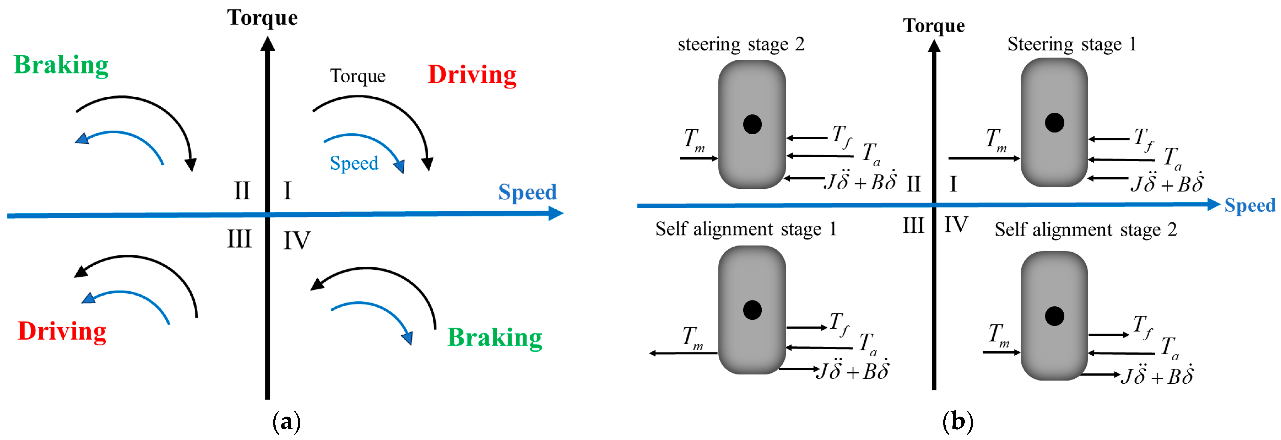
According to the standard PMSM torque–speed convention, the mechanical power of the motor is expressed as P m = T e ω m . When P m > 0 , the PMSM operates in the motoring mode and converts electrical energy into mechanical energy. When P m < 0 , the PMSM operates in the generating mode and converts mechanical energy into electrical energy. Therefore, regenerative operation occurs when T e ω m < 0 . This condition corresponds to the second or fourth quadrant of the standard PMSM torque–speed plane. Specifically, when ω m > 0 and T e <   0 , the PMSM operates in the second quadrant. When ω m < 0 and T e >   0 , the PMSM operates in the fourth quadrant. Both cases represent regenerative operation.
During the steering process, the front-wheel angle first changes from zero to the target value. This process can be divided into a steering acceleration stage and a steering deceleration stage. In the steering acceleration stage, the PMSM provides driving torque to overcome the self-aligning torque, friction torque, and steering-system inertia. Electrical energy is converted into mechanical energy, and the PMSM operates in the motoring mode. In the steering deceleration stage, the motor torque may become opposite to the motor speed for a short time, so transient regenerative braking may occur. However, this process is short and is not the main energy-recovery stage studied in this paper.
During the return-to-center process, the front-wheel angle decreases from the target value to zero under the action of self-aligning torque. If the self-aligning torque is larger than the combined resisting torques, the self-aligning torque provides mechanical input to the PMSM shaft. To regulate the return speed, the PMSM generates an electromagnetic braking torque. Under this condition, the electromagnetic torque and the motor speed have opposite signs, and the PMSM enters the regenerative mode. This interval is referred to as the return-to-center regenerative stage in this paper.
It should be emphasized that the term “return-to-center regenerative stage” denotes the third stage of the steering process, rather than the third quadrant of the standard PMSM torque–speed plane. Depending on the sign of the motor speed, the same return-to-center regenerative process may correspond to either the second or the fourth quadrant of the PMSM torque–speed plane.
When the self-aligning torque becomes smaller than the combined resisting torques, the actuator may need to draw energy from the DC bus to complete the return motion or maintain the desired steering trajectory. This interval is defined as the assisted return stage. In this case, the PMSM operates in the motoring mode.
Figure 2 illustrates the relationship between the PMSM torque–speed quadrant and the steering-process stages. The standard PMSM four-quadrant definition is used in Figure 2a, whereas Figure 2b describes the steering-process stages. Therefore, the quadrant number and the steering-stage number should not be interpreted as the same concept.
In summary, the energy-recovery stage discussed in this paper is the return-to-center regenerative stage of the steering process (Table 1). In the standard PMSM torque–speed plane, this regenerative operation belongs to QII or QIV, rather than QIII. This clarification is adopted throughout the revised manuscript to keep the sign convention consistent.
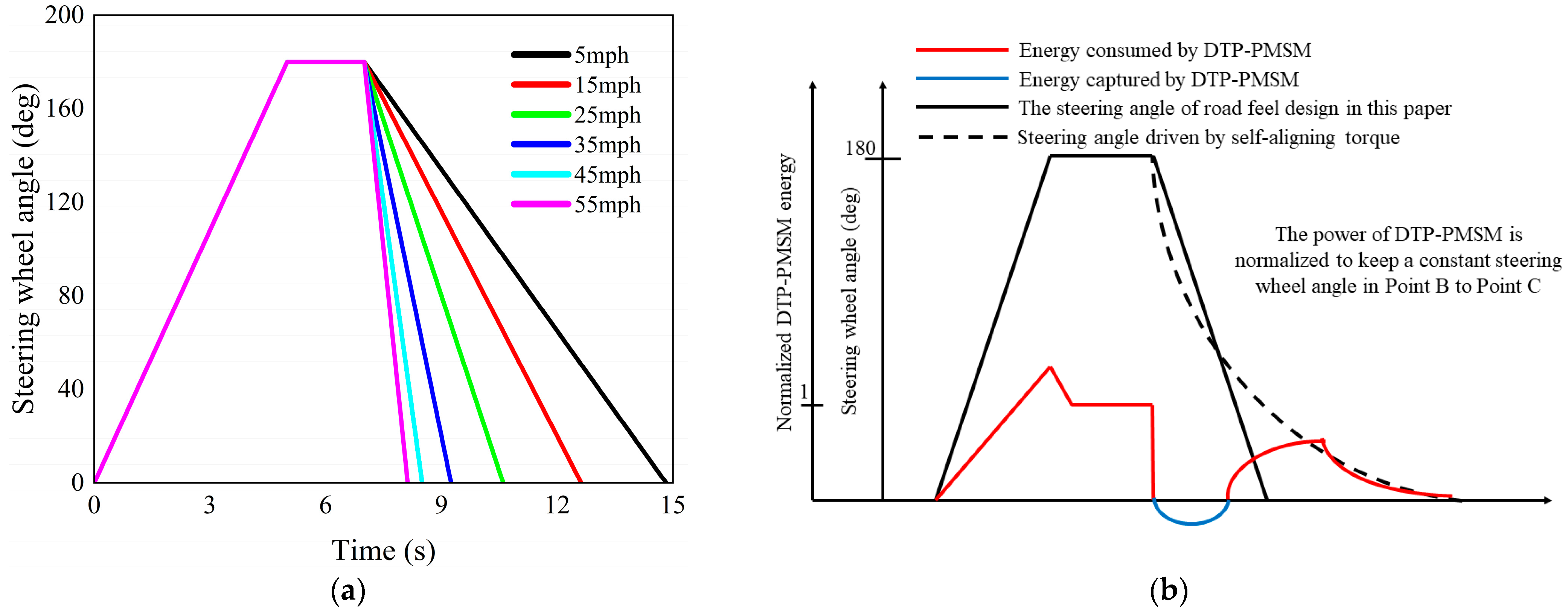
Figure 3a shows the relationship between the steering-wheel position and vehicle speed driven by the self-alignment torque. The steering wheel is turned to 180° by the driver and then released at point C. At point C, the driver allows the steering wheel to return freely to the center position using the self-alignment torque M z . The simulation does not account for the lateral force of the truck dynamics. Thus, plots shown at high truck speeds are only theoretical, as a 180°-steering-wheel-angle maneuver can cause a flip over of the truck. Figure 3a shows that the return speed of the steering wheel angle increases with vehicle speed.
An example of a steering maneuver is shown in Figure 3b, where the steering-wheel angle waveform and the required motor power over time are presented. At point A, a 180° steering of the steering wheel is initiated. It is assumed that the steering-wheel angle linearly changes with time for simplicity. It must be emphasized that 180° is the steering-wheel angle α and not the steer angle δ f . Assuming a steering ratio of 20:1, the steer angle becomes 9°. At point B, the steering wheel has turned to 180°. The increasing steering-wheel angle between points A and B results in a proportional increase in motor power (red trace) as the motor must provide power to overcome wheel friction forces and self-alignment torque.
When the steering wheel is at its commanded position that indicated as position B, the speed requirement of the motor is reduced to zero. As the motor has reached the desired steering angle, the motor is still consuming power to counteract the self-alignment torque M z to maintain the steering angle.
If the steering wheel were to be completely released, where the driver effectively releases the steering wheel, the self-alignment torque M z returns the wheels to the center-aligned position. With the wheels returning to the aligned position, the steering wheel is also returning to the aligned position. This natural path is indicated in Figure 3b as a dashed line from position C.
In practical steering operations, the steering command does not always coincide with the natural self-aligning path of the front wheels, as illustrated in Figure 3b. The solid segment from position C to D in Figure 3b represents a negative steering command, indicating that the operator or control system intentionally reduces the return-to-center speed of the front wheels. This mismatch between the commanded return speed and the self-aligning motion gives rise to excess power, which can be recovered when the PMSM controller of the steer-by-wire system operates in regenerative mode. At point D, the self-aligning effect becomes weaker than the commanded steering action, and the system returns from regenerative operation to power-consuming operation.
To utilize the recoverable energy induced by self-aligning torque, the PMSM inverter must support bidirectional power conversion during the return-to-center process. In the tested low-voltage steer-by-wire drive, the PMSM is selected such that its back electromotive force remains within the available DC-bus voltage range under the nominal return-to-center speed. However, this design condition does not mean that overvoltage or overspeed cannot occur under all operating conditions. High return speed, aggressive steering, large self-aligning torque, limited battery absorption capability, and repeated regenerative operation may still increase the DC-bus voltage and create an overvoltage risk. The peak back-EMF of the PMSM can be expressed as
e pk = P n ψ f | ω m |
where P n is the number of pole pairs, ψ f is the permanent-magnet flux linkage, and ω m is the mechanical angular speed. Considering the voltage limit of the inverter, regenerative operation should satisfy
e pk < U d c , available
where U d c , available is the available voltage margin of the DC-bus inverter system. For an SVPWM-based inverter, the available phase-voltage margin can be approximately related to the DC-bus voltage. Therefore, the corresponding safe mechanical speed boundary can be written as
U d c , available P n ψ f
When the return speed approaches this boundary, the controller reduces the regenerative current command and limits the recovered power. The q -axis current command is constrained by
i q = sat ( i q I max , I max )
and the q -axis voltage command is constrained by
u q = sat ( u q U max , U max )
where I max and U max are the allowable current and voltage limits of the PMSM drive. The regenerative power command is also limited as
P rec * = min ( P rec , P max )
where P max is the maximum allowable regenerative power determined by the inverter, DC bus, and low-voltage storage unit. In addition to current, voltage, and power limitations, the DC-bus voltage is monitored in real time. When U d c approaches a warning threshold U warn , the regenerative current command is reduced to slow down the charging of the DC-link capacitor. When U d c exceeds the braking activation threshold U br , the braking chopper is activated according to U d c and the excessive recovered energy is dissipated by the braking resistor as
P R = u d c 2 R L D
where D is the braking duty cycle, K br is the braking-chopper proportional gain, and R L is the braking resistance.
Therefore, the proposed energy-recovery strategy does not rely on the assumption that the back-EMF is always lower than the DC-bus voltage under every possible operating condition. Instead, regenerative operation is performed within speed, current, voltage, power, and DC-bus voltage constraints. Under normal test conditions, the back-EMF remains below the available DC-bus voltage, and the proposed controller regulates the recovered energy through the PMSM and DC bus. Under high-speed, aggressive steering, or limited energy-absorption conditions, the strategy automatically reduces the regenerative current and recovered power. If the DC-bus voltage still exceeds the safety threshold, the braking resistor is activated as a final overvoltage protection branch.
This protection mechanism ensures that safety and steering stability have higher priority than energy recovery. Consequently, the proposed method is mainly intended for low- to medium-speed return-to-center maneuvers, where recoverable SAT energy can be utilized while the actuator remains within the electrical and mechanical safety limits.


3. LESO-Based Bus-Voltage Stabilization Strategy During Return-to-Center Regenerative Operation

During the return-to-center regenerative operation, the self-aligning torque drives the PMSM steering actuator and part of the mechanical energy is converted into electrical energy. The recovered energy is fed back to the DC bus through the inverter. If the regenerative power is not regulated properly, the DC-bus voltage may rise rapidly and may even activate the braking resistor. Therefore, a bus-voltage stabilization strategy is required to regulate the recovered energy and maintain the DC-bus voltage near its rated value.
In conventional PMSM drive systems, an outer voltage loop and an inner current loop are usually adopted. The d -axis and q -axis current dynamics are decoupled by feedforward compensation. In this study, the proposed controller directly generates the q -axis voltage reference according to the DC-bus voltage-regulation objective. However, this does not mean that the current dynamics or coupling terms are ignored. Instead, the q -axis current dynamics, d q -axis coupling, back electromotive force, inverter loss, load variation, and SAT-induced regenerative power injection are regarded as lumped disturbances and estimated online by the linear extended state observer.
The PMSM voltage equations in the rotating reference frame can be written as
u d = R s i d + L d d i d d t ω r L q i q u q = R s i q + L q d i q d t + ω r L d i d + ψ f ω r
where u d and u q are the d-axis and q-axis voltages, i d and i q are the d -axis and q -axis currents, R s is the stator resistance, L d and L q are the d -axis and q -axis inductances, ω r is the electrical angular speed, and ψ f is the permanent-magnet flux linkage. The electrical power of the PMSM in the rotating reference frame is defined as
P e = 3 2 ( u d i d + u q i q )
where P e denotes the motoring condition in which electrical power is transferred from the DC bus to the PMSM, while P e < 0 denotes the regenerative condition in which electrical power is fed back from the PMSM to the DC bus. According to the DC-link capacitor energy balance, the DC-bus voltage dynamics can be expressed as P e , P L , P loss or equivalently,
C d c u d c d u d c d t = 3 2 u d i d + u q i q P L P loss
where C d c is the DC-link capacitance, U d c is the DC-bus voltage, P L is the equivalent low-voltage load power, and P loss represents inverter loss, machine loss, and other unmodeled power losses. Under regenerative operation, P e < 0 , and therefore the term P e becomes positive, which explains why the recovered energy tends to increase the DC-bus voltage. To avoid the nonlinear term u d c u ˙ d c , the squared DC-bus voltage is selected as the controlled state:
x 1 = u d c 2
Then,
x ˙ 1 = 2 u d c u ˙ d c
The first derivative of x 1 is defined as
x ˙ 1 = x 2
By differentiating the DC-bus voltage dynamics and combining them with the PMSM current equations, the second derivative of x 1 can be written in a compact form as
x ˙ 2 = F x 1 , x 2 , ω r , t + g ω r u
where u is the equivalent control input related to the q -axis voltage command, g ω r is the speed-dependent control gain, and F x 1 , x 2 , ω r , t is the lumped dynamic term. The lumped term includes SAT-induced regenerative power injection, PMSM parameter uncertainty, d q -axis current coupling, inverter loss, load variation, and other unmodeled disturbances.
The equivalent q -axis voltage input is defined as
u = u q R s i q ω r L d i d ψ f ω r
Therefore, the nominal q -axis voltage dynamics are separated from the back-EMF and feedforward compensation terms. The remaining parameter mismatch, current coupling, and regenerative disturbance are not neglected, but are included in the lumped term F ( x 1 , x 2 , ω r , t ) .
To construct the extended system, the lumped dynamic term is introduced as the extended disturbance state:
x 3 = F x 1 , x 2 , ω r , t
and its derivative is defined as
x ˙ 3 = G ( t )
where G ( t ) is the rate of variation in the lumped disturbance. Then, the third-order extended system can be obtained as
x ˙ 1 = x 2 x ˙ 2 = x 3 + g ω r u x ˙ 3 = G ( t ) y = x 1
In practical operation, G t is assumed to be bounded because the SAT variation, return speed, current, voltage, and regenerative power are all limited by physical constraints and controller saturation.
The physical meanings of the extended states and variables are summarized in Table 2.
In this study, a linear extended state observer is adopted rather than a nonlinear extended state observer. The reason is that the low-voltage steer-by-wire system requires simple real-time implementation, and excessive nonlinear observer gain may amplify voltage-sensor noise and introduce q-axis voltage fluctuation. Moreover, the dominant disturbance in the studied operation is the SAT-induced regenerative power injection, which can be effectively estimated by a properly tuned LESO.
The third-order LESO is designed as
e = z 1 y z ˙ 1 = z 2 β 1 e z ˙ 2 = z 3 β 2 e + g ω r u   z ˙ 3 = β 3 e
where ( z 1 , z 2 , z 3 ) are the estimates of ( x 1 , x 2 , x 3 ) , respectively, and ( β 1 , β 2 , β 3 ) are the observer gains. The observer gains are selected using the bandwidth method:
β 1 = 3 ω o β 2 = 3 ω o 2 β 3 = ω o 3
where ω o is the observer bandwidth. The corresponding characteristic polynomial of the nominal observer error dynamics is
s 3 + β 1 s 2 + β 2 s + β 3 = s + ω o 3
Therefore, the observer error system is Hurwitz stable when ω o > 0 . If G t is bounded, the LESO estimation error is also bounded. A larger ω o improves disturbance-estimation speed, but an excessively large observer bandwidth may amplify measurement noise. Therefore, the observer bandwidth is selected according to
3 ω c ω o 10 ω c
and it should also satisfy the sampling-frequency limitation
ω o < 1 5 ω s
where ω c is the desired closed-loop bus-voltage bandwidth and ω s is the sampling angular frequency.
The bus-voltage control law is designed as
u = k p y * z 1 k d z 2 z 3 g ω r
where y * = ( u d c * ) 2 is the reference of the squared DC-bus voltage, and k p and k d are the voltage-loop control gains. The q-axis voltage reference is reconstructed as
u q * = u + R s i q + ω r L d i d + ψ f ω r
The controller gains are selected according to a second-order closed-loop bandwidth criterion:
k p = ω c 2 , k d = 2 ζ ω c
where ζ is the damping ratio. Substituting the control law into the extended system gives the approximate closed-loop error dynamics
e ¨ + k d e ˙ + k p e = d ˜ ( t )
where d ˜ ( t ) is the residual disturbance-estimation error. Since k p > 0 and k d > 0 , the polynomial s 2 + k d s + k p is Hurwitz stable. Therefore, under bounded LESO estimation error, the DC-bus voltage tracking error is ultimately bounded.
To improve implementation safety under high-frequency current fluctuations and regenerative power pulses, the q-axis current and q-axis voltage commands are limited as
i q = sat i q I max , I max u q = sat u q U max , U max
where I max and U max are the allowable current and voltage limits of the PMSM drive. When the DC-bus voltage approaches the warning threshold, the regenerative current command is reduced. When the voltage exceeds the braking threshold, the braking chopper is activated as the final protection branch.
Therefore, the proposed single-loop bus-voltage control method does not bypass current decoupling in an uncontrolled manner. Instead, it combines feedforward compensation, LESO-based disturbance estimation, voltage-error feedback, and saturation protection to suppress the influence of current coupling, SAT-induced energy injection, and high-frequency current fluctuations.

4. Experimental Result

4.1. Experimental Equipment

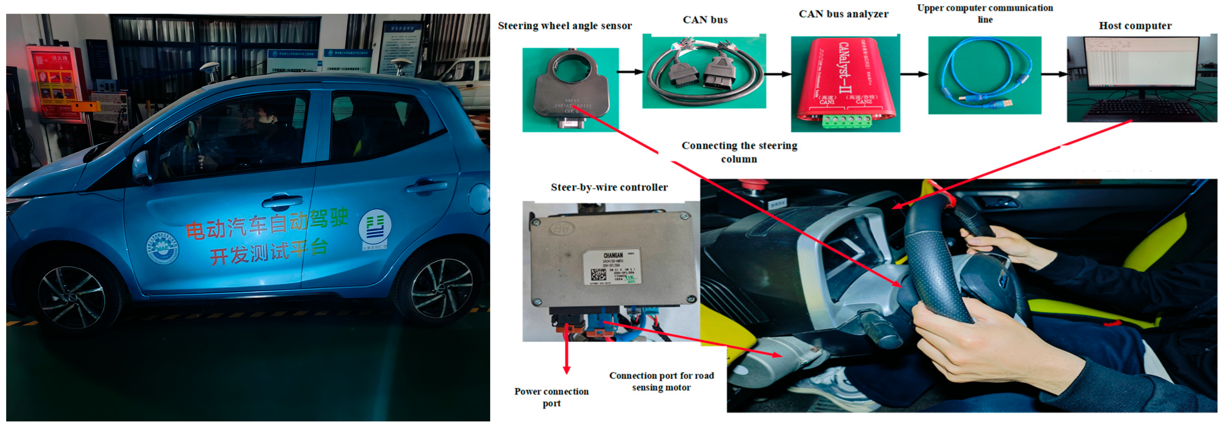
In order to test the effectiveness of the proposed strategy, this article conducted relevant experiments using an electric vehicle autonomous-driving development and testing platform that includes a steer-by-wire system. Testing includes the steering angle sensor, CAN bus, CAN bus analyzer, upper computer, and controller. As shown in Figure 4 below.
To improve the reproducibility of the experimental validation, the key parameters of the PMSM-driven steer-by-wire platform are summarized in Table 3. Only the parameters directly related to the PMSM model, DC-bus energy balance, braking protection, and ADRC-ESO controller are listed to avoid unnecessary expansion of the experimental section.
The torque constant K t can be obtained from the PMSM datasheet or calculated by K t = 3 2 P n ψ f . The LESO gains are not listed separately because they are determined by the bandwidth method, namely β 1 = 3 ω o , β 2 = 3 ω o 2 , and β 3 = ω o 3 , as described in Section 3. Similarly, the voltage-loop gains k p and k d are calculated from ω c and the damping ratio. Therefore, Table 3 only lists the independent parameters required for reproducing the experimental platform and controller setup.
Although the experimental platform used in this study is based on a specific passenger-car autonomous-driving test vehicle, it serves as an effective validation platform for the proposed steer-by-wire control strategy in new energy vehicle applications. The main reason is that the objective of this study is to verify the control mechanism at the steering actuation and low-voltage electrical level, which represents a general architectural design for modern electrified chassis. In particular, the key components involved in the proposed method—including the PMSM-driven steer-by-wire actuator, steering-angle sensing, controller, CAN communication chain, and low-voltage DC-bus power architecture—are highly consistent with the standard configurations required by various new energy vehicles and intelligent mobile platforms. Therefore, the passenger-car-based test platform provides a representative and generalized environment for evaluating the feasibility of self-aligning-torque energy recovery, DC-bus voltage stabilization, and controller dynamic performance.

4.2. Simulation of Return-to-Center Regenerative Operation and Bus-Voltage Stabilization

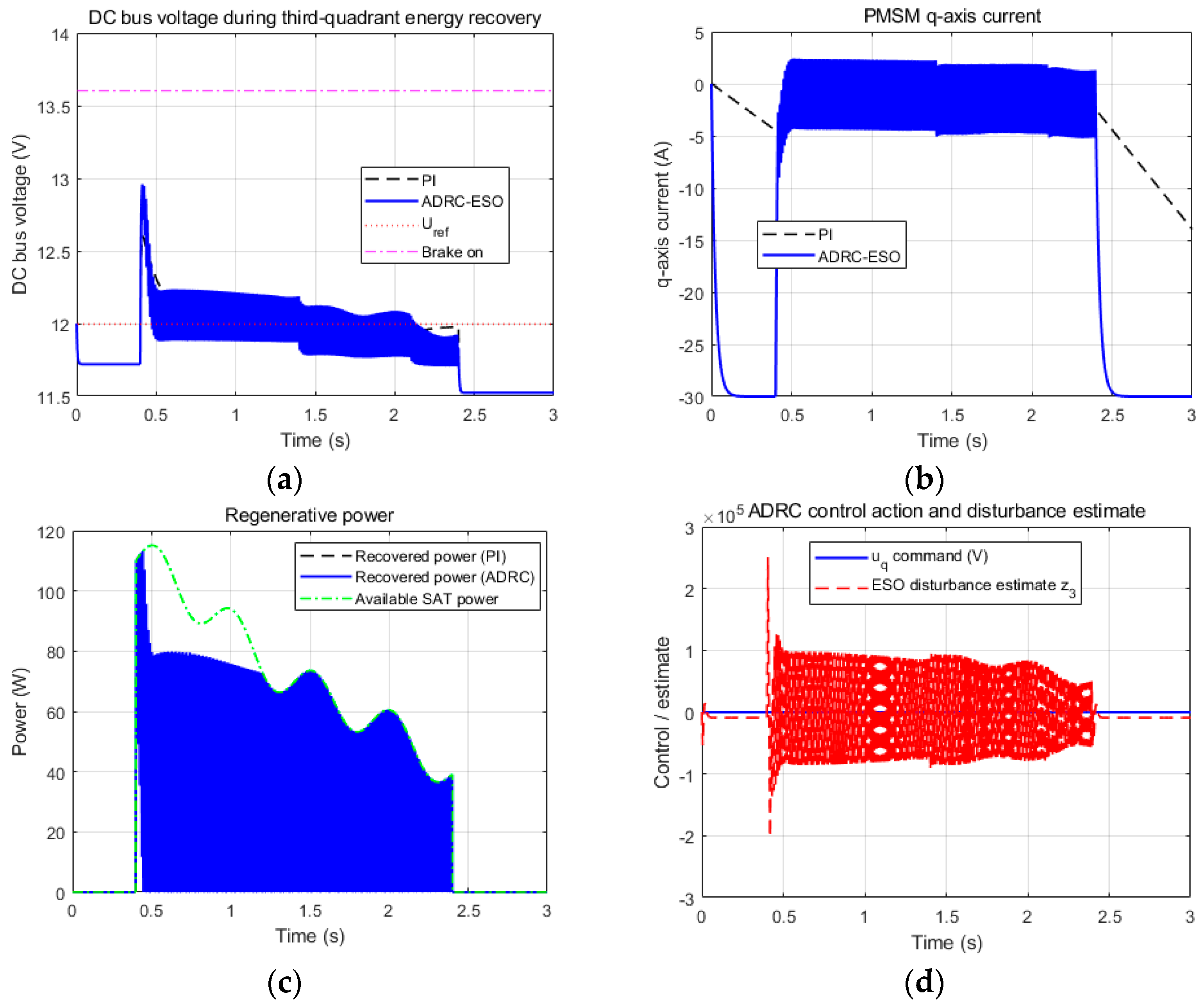
Figure 5 shows the dynamic responses of the PMSM-driven steer-by-wire system during the return-to-center regenerative operation. In this interval, the self-aligning torque provides mechanical input to the PMSM, and the PMSM operates in the regenerative mode when the electromagnetic torque and motor speed have opposite signs. The recovered energy is fed back to the DC bus through the inverter. Therefore, bus-voltage stabilization is required to prevent excessive voltage rise caused by regenerative energy injection.
As shown in Figure 5a, both the conventional PI controller and the proposed ADRC-ESO controller can regulate the DC-bus voltage around the rated value of 12 V. However, the proposed ADRC-ESO controller exhibits better voltage-regulation performance. After the regenerative operation starts at approximately 0.4 s, the DC-bus voltage under ADRC-ESO rises to about 12.9–13.0 V and then quickly returns toward the rated voltage. During most of the regenerative interval from approximately 0.5 s to 2.4 s, the DC-bus voltage is maintained within about 11.8–12.2 V. The peak voltage remains below the braking activation threshold of 13.6 V, indicating that the proposed controller can suppress the voltage rise caused by regenerative power injection.
Figure 5b shows the q-axis current response. During the return-to-center regenerative operation, the q-axis current varies within a limited range and is mainly distributed between approximately −5 A and 2 A. This indicates that the controller adjusts the electromagnetic braking torque to regulate the wheel return speed and the DC-bus voltage simultaneously.
Figure 5c compares the available self-aligning-torque power and the recovered power. At the beginning of the regenerative interval, the available SAT power reaches approximately 110–115 W, while the recovered power under ADRC-ESO reaches approximately 75–80 W. As the front wheel approaches the center position, both the available SAT power and the recovered power gradually decrease. This result shows that the return-to-center process provides a measurable regenerative energy source and that the proposed controller can regulate part of this energy into the DC bus.
Figure 5d shows the ADRC control action and the LESO disturbance estimation. The estimated disturbance varies significantly during the regenerative interval, especially near the beginning of energy recovery. This indicates that the LESO captures the lumped influence of SAT-induced power injection, PMSM parameter uncertainty, current coupling, load variation, and other unmodeled disturbances. By compensating for this estimated disturbance, the proposed ADRC-ESO controller improves DC-bus voltage regulation during regenerative operation.
It should be noted that the DC-bus voltage remains below the braking threshold in this controlled simulation. Therefore, the braking resistor is not activated in this case. This result should be interpreted as the effect of successful voltage stabilization rather than evidence that the braking branch is unnecessary.
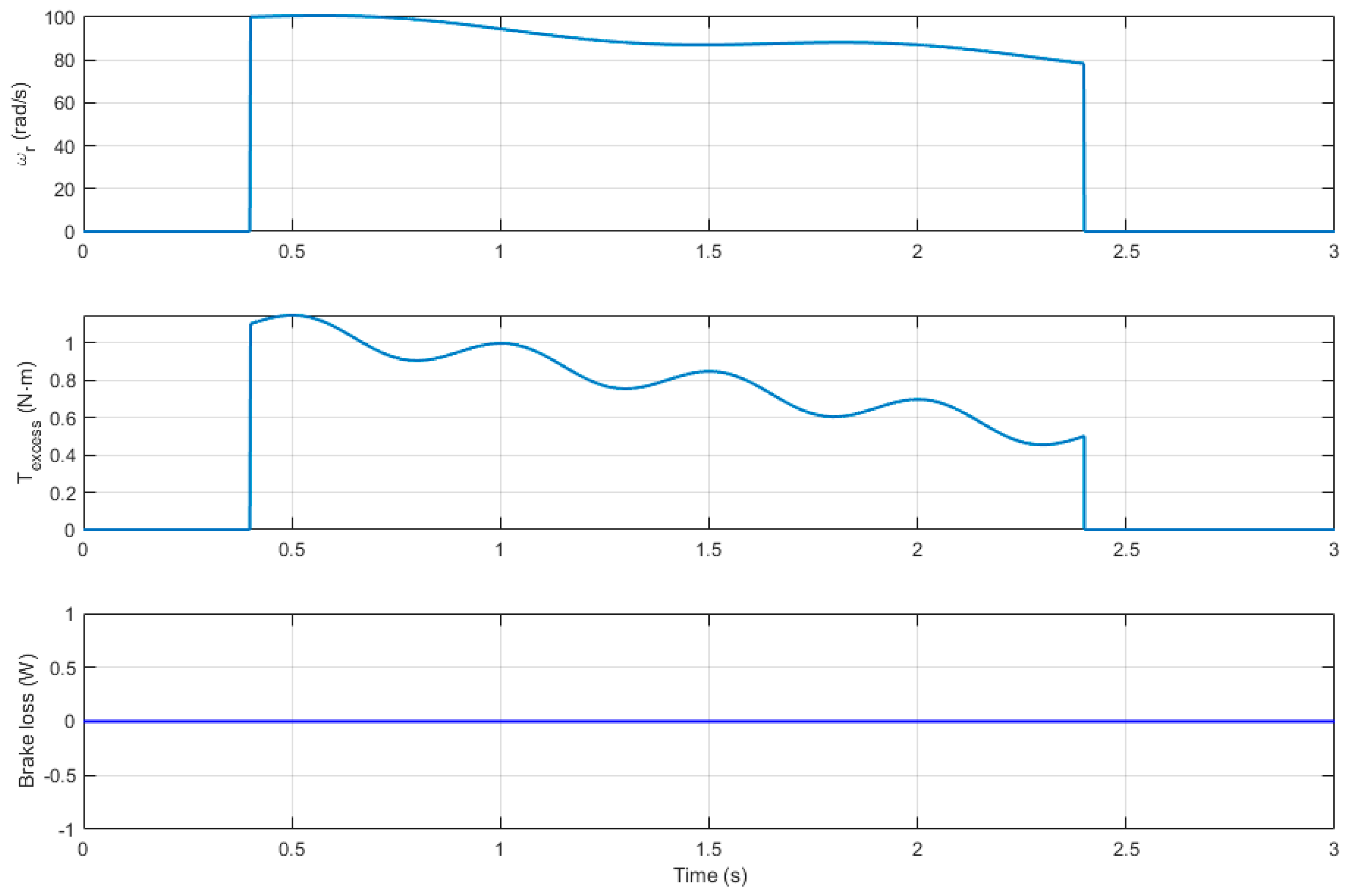
Figure 6 further illustrates the regenerative operating profile and the braking-resistor loss under the proposed ADRC-ESO controller. During the interval from approximately 0.4 s to 2.4 s, the PMSM remains in the return-to-center regenerative operation. The motor speed first rises rapidly to approximately 100 rad/s and then gradually decreases to about 78–80 rad/s. Meanwhile, the excess self-aligning torque increases to approximately 1.1 N·m at the beginning of regeneration and then gradually decreases to about 0.5 N·m. This confirms that the self-aligning torque continuously provides recoverable mechanical input during the main return-to-center interval.
The braking-resistor loss remains approximately zero during the entire controlled regenerative process. This is because the proposed ADRC-ESO controller regulates the recovered power and keeps the DC-bus voltage below the braking activation threshold. According to the braking-resistor model in Section 2.3, the braking duty cycle is zero when ( u d c U br ) . Therefore, no energy is dissipated by the braking resistor under the tested controlled condition.
This result does not mean that overvoltage risk does not exist. Instead, it indicates that the proposed controller prevents the DC-bus voltage from exceeding the braking threshold under the simulated return-to-center condition. If the recovered power becomes larger due to a higher return speed, larger self-aligning torque, smaller DC-link capacitance, limited low-voltage power-source absorption capability, or insufficient bus-voltage control, the DC-bus voltage may exceed U br , and the braking branch will be activated as an overvoltage protection mechanism. Therefore, the braking resistor is retained as a necessary safety branch, although it is not activated in the controlled case shown in Figure 6.
In summary, the simulation results in Figure 5 and Figure 6 demonstrate that the proposed ADRC-ESO strategy can regulate the DC-bus voltage during return-to-center regenerative operation and avoid unnecessary braking-resistor dissipation under the tested condition. The braking branch is not activated because the DC-bus voltage is maintained below the threshold, rather than because regenerative overvoltage is impossible. In practical operation, the braking resistor still serves as the final protection branch under excessive regenerative power or limited energy absorption capability.

4.3. Long-Duration Cyclic Energy-Recovery and Energy-Accounting Performance

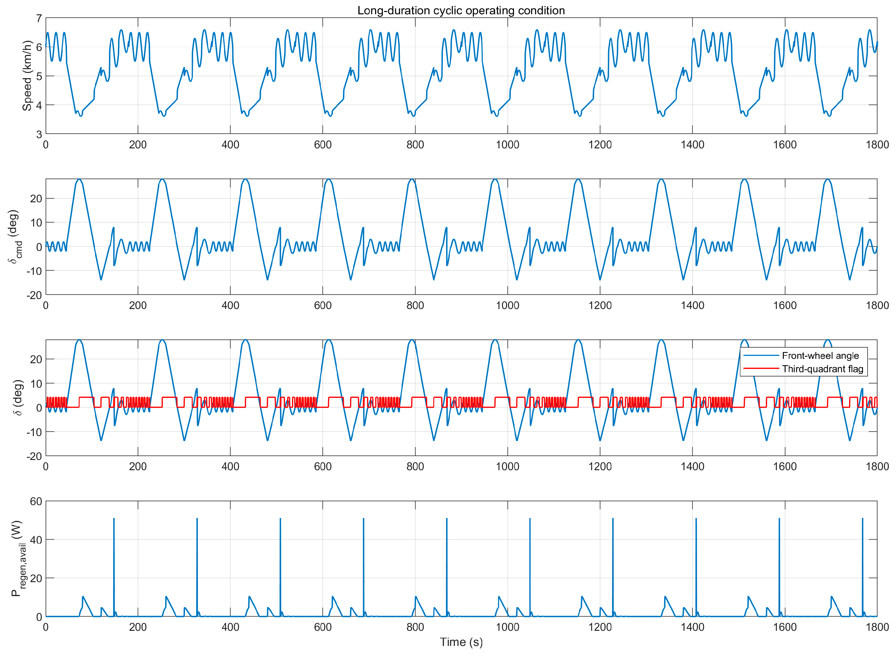
To evaluate the energy-saving capability of the proposed strategy under long-duration repetitive operation, a cyclic steering condition was constructed for the PMSM-driven steer-by-wire system, as shown in Figure 7. The total simulation time was set to 1800 s to represent prolonged operation typical of new energy vehicles under frequent low-speed maneuvering, such as urban driving or repetitive parking profiles. During the simulation, the vehicle speed varied periodically within a low-speed range of approximately 3.5–6.5 km/h, while the steering command was repeatedly applied to generate successive steering, holding, and return-to-center processes. The commanded steering angle varied roughly within ± 25 ° , and the front-wheel angle evolved correspondingly under the steer-by-wire control framework. A regenerative-operation flag was introduced to identify the intervals in which the PMSM entered generating operation during wheel return. This flag becomes active when the self-aligning torque provides sufficient mechanical input, and the electromagnetic torque is opposite to the motor speed. Under this condition, the instantaneous regenerative power of the PMSM was calculated to characterize the temporal distribution of recoverable energy during long-duration cyclic steering.
Figure 7 shows the long-duration cyclic steering condition together with the corresponding return-to-center regenerative power profile of the PMSM-driven steer-by-wire system. Over the entire 1800s interval, the vehicle speed and steering command exhibit clear periodic characteristics, indicating that the constructed scenario is suitable for evaluating cumulative energy recovery under repeated steering maneuvers. The front-wheel angle follows the cyclic command with regular return-to-center phases, and the regenerative-operation flag is activated intermittently during these return intervals. This indicates that regenerative operation does not occur continuously, but only when the self-aligning torque provides sufficient mechanical input to drive the PMSM into the generating state.
The regenerative power curve further confirms this mechanism. During most non-return intervals, the regenerative power remains close to zero, whereas distinct power peaks appear repeatedly during return-to-center regenerative operation. From the figure, the highest instantaneous regenerative power reaches approximately 50 W, while smaller recovery events are mainly below about 10 W. More importantly, these regenerative pulses appear repeatedly and consistently throughout the entire 1800s simulation, indicating that the recoverable energy is accumulated through many short-duration return-to-center events rather than through a single continuous recovery process. This behavior is consistent with the operating characteristics of new energy vehicles in urban or parking environments, where steering maneuvers are typically low-speed, frequent, and repetitive.
From the perspective of energy-saving significance, Figure 8 demonstrates that the proposed return-to-center regenerative mechanism has clear long-term application potential. Although the recovered energy in each individual event is limited, the repeated occurrence of regenerative intervals makes the cumulative recovery effect non-negligible over prolonged operation. Therefore, this operating profile provides an appropriate basis for comparing the real-time recovered power and cumulative energy-recovery tendency among different control strategies.
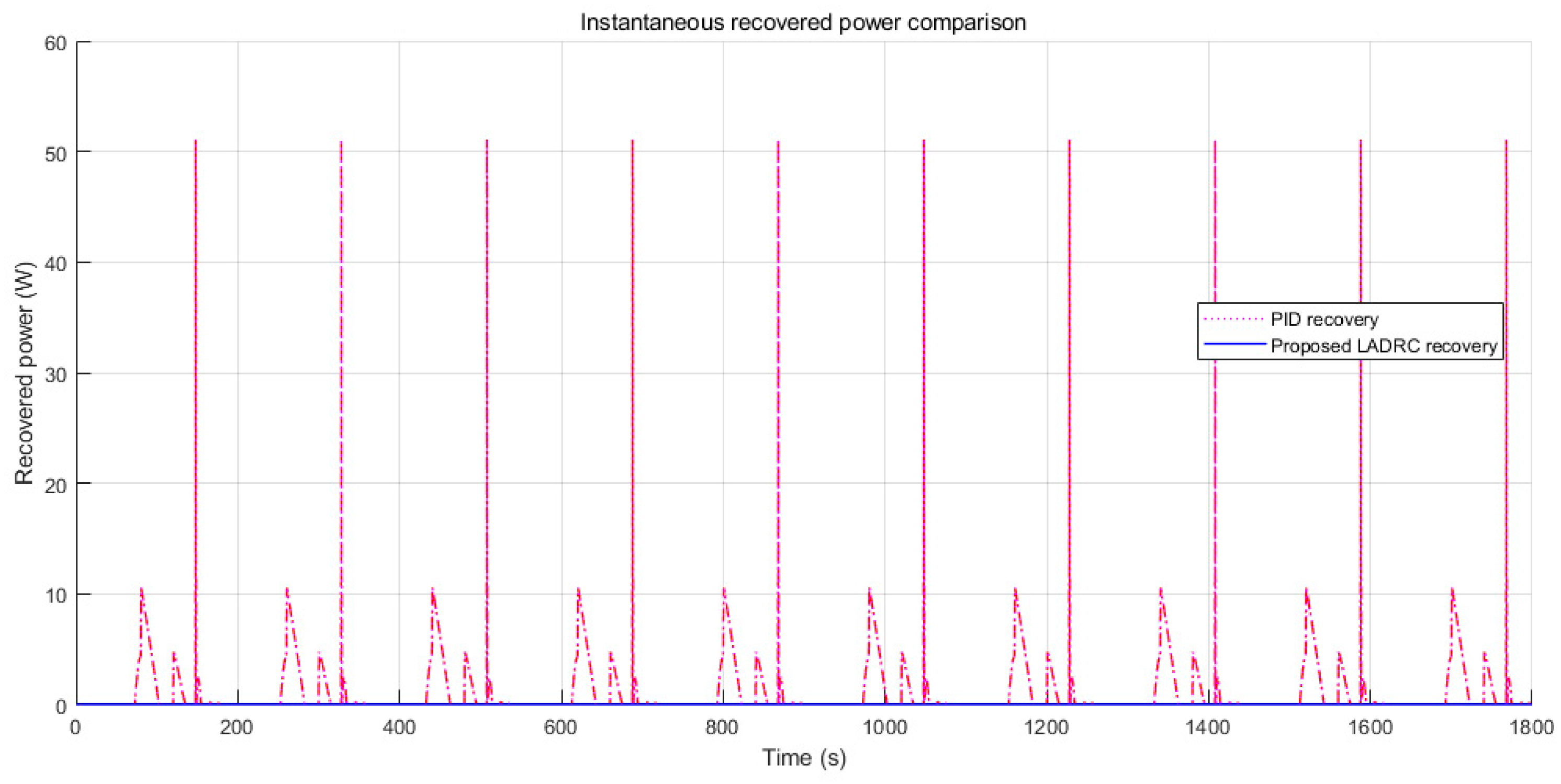
To further compare the real-time energy-recovery capability of different control strategies under prolonged operation, the same 1800s cyclic steering condition was used for the PMSM-driven steer-by-wire system, as shown in Figure 8. Under each return-to-center event satisfying the regenerative-operation condition, the instantaneous recovered power on the electrical side was calculated and compared for four strategies, namely traditional dissipation, PI recovery, PID recovery, and the proposed LADRC-based recovery method. It should be noted that the recovered power shown in Figure 8 represents the gross electrical-side recovered power. The actual net recovered energy should be evaluated after deducting PMSM loss, inverter loss, mechanical loss, DC-link loss, and braking-resistor loss according to the energy-balance model in Section 2.3.
Figure 8 compares the instantaneous gross recovered power of different control strategies under the long-duration cyclic steering condition. The recovered power exhibits a clearly pulsating pattern rather than a continuous profile, indicating that regenerative energy is generated only during specific return-to-center intervals instead of throughout the entire steering cycle. This behavior is consistent with the return-to-center regenerative mechanism, in which recoverable energy appears only when the self-aligning torque provides sufficient mechanical input to drive the PMSM into the generating state.
As shown in the figure, the traditional dissipation strategy remains essentially at 0 W over the whole 1800 s interval, indicating that the available excess energy is not retained on the electrical side. In contrast, all recovery-based strategies produce repeated positive power pulses, confirming that the long-duration cyclic steering process contains multiple short-duration regenerative opportunities. The dominant recovery peaks appear periodically and reach approximately 50–51 W, while smaller secondary pulses are mainly below about 10 W. This indicates that the recoverable energy is not uniformly distributed, but is concentrated in several major return events within each steering cycle.
Among the compared strategies, the PI-based method mainly captures low-amplitude pulses and shows relatively limited real-time energy-capture capability, whereas the higher-performance recovery strategies are able to retain the dominant energy packets during the principal regenerative intervals. From an engineering perspective, the most important feature of Figure 8 is the repeatability of these regenerative power pulses over the full 1800 s period. Although each individual recovery event is short and limited in magnitude, the repeated occurrence of these events allows the total recoverable energy to accumulate over time. Therefore, the energy-saving effect of the steer-by-wire system is not determined by a single large recovery event, but by the cumulative contribution of many repeated return-to-center regenerative processes. These results provide direct evidence that long-duration repetitive steering operation can produce a non-negligible cumulative energy-recovery potential.
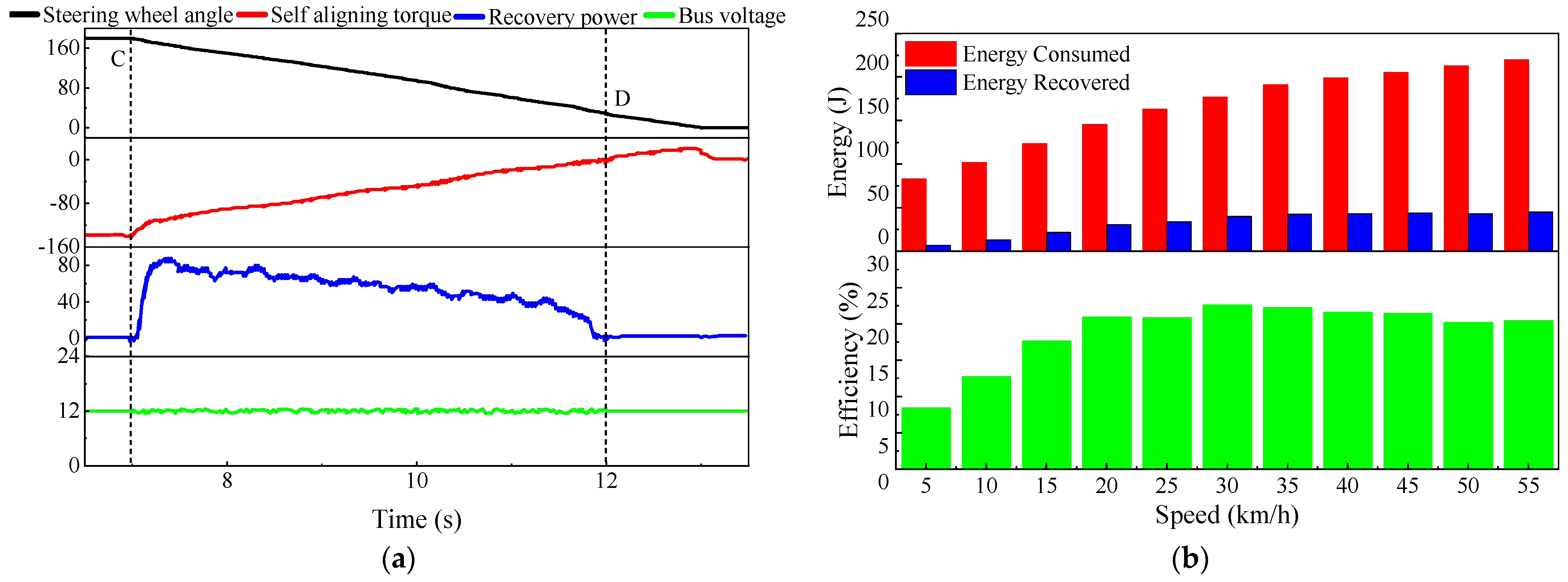
Figure 9a shows the measurement waveform when the vehicle speed is 30 km/h and the wheel return time is 6 s. During the 6 s self-alignment process, the effective energy-capture interval is approximately 4.8 s. Within this interval, the DC-bus voltage fluctuates because of the interaction between the power supply unit, which attempts to maintain a constant voltage of 12 V, and the PMSM, which operates in the return-to-center regenerative mode.
Figure 9b shows the energy consumed by the PMSM during a complete steering maneuver and the portion that can be captured during the return phase. When the vehicle speed is higher than 20 km/h, about 20% of the steering-actuator energy can be captured at the gross electrical-energy level under the tested condition. This percentage should be interpreted as the actuator-side gross captured energy ratio, rather than as the final net recovered energy or direct vehicle-level energy-saving ratio. According to the energy-balance model in Section 2.3, the net recovered energy should be obtained after deducting PMSM copper loss, iron loss, inverter loss, mechanical loss, DC-link loss, and possible braking-resistor loss. Therefore, the actual net energy benefit is lower than the gross captured energy shown in Figure 9b.
Considering vehicle stability, once the speed exceeds 30 km/h, the driver will normally not allow the steering wheel to return at the maximum self-aligning rate. In this case, energy capture is no longer the primary target, and steering safety and vehicle stability should be prioritized. Therefore, the proposed strategy is more suitable for repeated low- to medium-speed steering maneuvers, such as urban driving, lane correction, roundabouts, and parking. Under these conditions, repeated return-to-center events can accumulate recoverable energy over time and reduce part of the net electrical demand of the steer-by-wire actuator.
In summary, the long-duration simulation and single self-alignment experiment demonstrate that SAT-induced regenerative energy appears intermittently during repeated return-to-center events. The reported recovered power and energy ratio represents the gross actuator-side recovery capability. The actual net recovered energy should be evaluated together with the loss terms defined in Section 2.3. This clarification avoids overestimating the vehicle-level energy benefit while still confirming the feasibility of the proposed regenerative strategy.

5. Conclusions

This paper investigated a self-aligning-torque-induced energy-recovery mechanism and a corresponding DC-bus voltage stabilization strategy for a PMSM-driven steer-by-wire system in new energy vehicles. The main conclusions are summarized as follows.
First, an electromechanical energy-flow model was established for the PMSM-driven steer-by-wire system during the front-wheel return-to-center process. The standard PMSM torque–speed sign convention was clarified to avoid confusion between the PMSM operating quadrant and the steering-process stage. The analysis shows that when the self-aligning torque provides sufficient mechanical input, and the electromagnetic torque is opposite to the motor speed, the PMSM enters regenerative operation, and the otherwise dissipated mechanical energy can be redirected to the DC bus.
Second, a practical energy-balance model was introduced to describe the distribution of SAT-induced recoverable energy. Different from the ideal assumption that all excess mechanical energy is stored in the DC-link capacitor, the revised model considers DC-link energy variation, low-voltage power-source absorption, PMSM copper loss, iron loss, inverter loss, mechanical loss, and braking-resistor loss. Therefore, the actual energy benefit should be evaluated using net recovered energy after deducting losses, rather than only using the gross electrical energy captured at the DC-bus side.
Third, a LESO-based ADRC bus-voltage stabilization strategy was developed for return-to-center regenerative operation. The proposed controller directly generates the q-axis voltage reference according to the DC-bus voltage-regulation objective. Current coupling, back-EMF variation, regenerative power injection, load variation, and parameter uncertainty are treated as lumped disturbances and estimated by the LESO. The simulation results show that the proposed controller maintains the DC-bus voltage mainly within 11.8–12.2 V, with a transient peak of about 12.9–13.0 V, which remains below the 13.6 V braking activation threshold under the tested condition. This indicates that the proposed method can suppress regenerative voltage rise while avoiding unnecessary braking-resistor dissipation.
Fourth, the long-duration cyclic steering simulation and the single self-alignment experiment verify the feasibility of repeated return-to-center energy recovery. Under the tested 30 km/h self-alignment condition, the wheel return time is about 6 s, and the effective energy-capture interval is approximately 4.8 s. When the vehicle speed is higher than 20 km/h, about 20% of the steering-actuator energy can be captured at the gross electrical-energy level under the tested condition. This ratio should be interpreted as the actuator-side gross captured energy ratio, rather than the final net recovered energy or direct vehicle-level energy-saving ratio. The actual net benefit depends on PMSM losses, inverter losses, mechanical losses, DC-link losses, braking-resistor losses, and the energy absorption capability of the low-voltage power source.
Finally, the proposed strategy is mainly suitable for repeated low- to medium-speed return-to-center maneuvers, such as urban driving, lane correction, roundabouts, and parking scenarios. Under high-speed, large-steering-angle, low-adhesion, or aggressive steering conditions, tire nonlinearities, load transfer, steering compliance, backlash, and road-friction variation may significantly affect the self-aligning torque. Future work will combine nonlinear tire models, high-fidelity vehicle dynamics simulation, and hardware-in-the-loop or road-test validation to further quantify the vehicle-level net energy benefit of the proposed strategy.

Author Contributions

Conceptualization, H.W. and H.Y.; methodology, J.L.; software, J.L.; validation, H.W., B.L. and H.Y.; formal analysis, J.L.; investigation, H.W.; resources, H.W.; data curation, H.W.; writing—original draft preparation, H.Y.; writing—review and editing, B.L.; visualization, J.L.; supervision, F.W.; project administration, F.W.; funding acquisition, H.Y. All authors have read and agreed to the published version of the manuscript.

Funding

This research was funded by Department of Science and Technology of Shandong Province (ZR2022ME078).

Institutional Review Board Statement

Not applicable.

Informed Consent Statement

Not applicable.

Data Availability Statement

The original contributions presented in this study are included in the article. Further inquiries can be directed to the corresponding authors.

Conflicts of Interest

The authors declare no conflict of interest.

References

  1. Morton, C.; Pickert, V.; Armstrong, M. Self-Alignment Torque as a Source of Energy Recovery for Hybrid Electric Trucks. IEEE Trans. Veh. Technol. 2014, 63, 62–71. [Google Scholar] [CrossRef]
  2. Dell’Orto, G.; Ballo, F.M.; Gobbi, M.; Mastinu, G. Twisting Torque—A Simplified Theoretical Model for Bicycle Tyres. Measurement 2023, 221, 113524. [Google Scholar] [CrossRef]
  3. Cui, T.; Zhao, W.; Tai, K. Optimal Design of Electro-Hydraulic Active Steering System for Intelligent Transportation Environment. Energy 2021, 214, 118911. [Google Scholar] [CrossRef]
  4. Zhao, W.; Zhou, X.; Wang, C.; Luan, Z. Energy Analysis and Optimization Design of Vehicle Electro-Hydraulic Compound Steering System. Appl. Energy 2019, 255, 113713. [Google Scholar] [CrossRef]
  5. Zou, S.C.; Zhao, W.Z. Optimization Strategy of Vehicle DCS System Based on APSO Algorithm. Energy 2020, 208, 118801. [Google Scholar] [CrossRef]
  6. Abu Hanifah, R.; Toha, S.F.; Ahmad, S.; Hassan, M.K. Swarm-Intelligence Tuned Current Reduction for Power-Assisted Steering Control in Electric Vehicles. IEEE Trans. Ind. Electron. 2018, 65, 7202–7210. [Google Scholar] [CrossRef]
  7. Abu Hanifah, R.; Toha, S.F.; Hassan, M.K.; Ahmad, S. Power Reduction Optimization with Swarm Based Technique in Electric Power Assist Steering System. Energy 2016, 102, 444–452. [Google Scholar] [CrossRef]
  8. Zhao, H.; Wang, B.; Zhang, G.; Feng, Y. Energy Saving Design and Control of Steering Wheel System of Steering by Wire Vehicle. IEEE Access 2019, 7, 44307–44316. [Google Scholar] [CrossRef]
  9. Hu, S.; Liang, Z.; Zhang, W.; He, X. Research on the Integration of Hybrid Energy Storage System and Dual Three-Phase PMSM Drive in EV. IEEE Trans. Ind. Electron. 2018, 65, 6602–6611. [Google Scholar] [CrossRef]
  10. Mese, E.; Yasa, Y.; Akca, H.; Aydeniz, M.G.; Garip, M. Investigating Operating Modes and Converter Options of Dual Winding Permanent Magnet Synchronous Machines for Hybrid Electric Vehicles. IEEE Trans. Energy Convers. 2015, 30, 285–295. [Google Scholar] [CrossRef]
  11. Hu, S.; Xiong, M.; Liang, Z.; He, X. Torque Distributed Control Strategy for the Dual Three-Phase PMSM in Hybrid Energy Storage System Application. IEEE Trans. Ind. Electron. 2019, 66, 2544–2552. [Google Scholar] [CrossRef]
  12. Hu, Y.; Li, X. Fault Tolerant Control of Dual Three-phase PMSG Wind Turbine Drive System with One Channel of Faulty Rectifier. IET Renew. Power Gener. 2020, 14, 2135–2141. [Google Scholar] [CrossRef]
  13. Lang, X.; Yang, T.; Bai, G.; Bozhko, S.; Wheeler, P. Active Disturbance Rejection Control of DC-Bus Voltages Within a High-Speed Aircraft Electric Starter/Generator System. IEEE Trans. Transp. Electrif. 2022, 8, 4229–4241. [Google Scholar] [CrossRef]
  14. Hu, Y.; Odavic, M.; Zhu, Z.Q. DC Bus Voltage Pulsation Suppression of the Permanent Magnet Synchronous Generator With Asymmetries Accounting for Torque Ripple. IEEE Trans. Energy Convers. 2016, 31, 1080–1089. [Google Scholar] [CrossRef]
  15. Kenné, G.; Goma, R.; Nkwawo, H.; Lamnabhi-Lagarrigue, F.; Arzandé, A.; Vannier, J.C. Real-time Transient Stabilization and Voltage Regulation of Power Generators with Unknown Mechanical Power Input. Energy Convers. Manag. 2010, 51, 218–224. [Google Scholar] [CrossRef]
  16. Ali, M.; Yaqoob, M.; Cao, L.; Loo, K.H. Disturbance-Observer-Based DC-Bus Voltage Control for Ripple Mitigation and Improved Dynamic Response in Two-Stage Single-Phase Inverter System. IEEE Trans. Ind. Electron. 2019, 66, 6836–6845. [Google Scholar] [CrossRef]
  17. Qu, S.; Zappaterra, F.; Vacca, A.; Busquets, E. An Electrified Boom Actuation System with Energy Regeneration Capability Driven by a Novel Electro-Hydraulic Unit. Energy Convers. Manag. 2023, 292, 117443. [Google Scholar] [CrossRef]
  18. Long, G.; Ding, F.; Zhang, N.; Zhang, J.; Qin, A. Regenerative Active Suspension System with Residual Energy for In-Wheel Motor Driven Electric Vehicle. Appl. Energy 2020, 260, 114180. [Google Scholar] [CrossRef]
  19. Xu, Y.; Zhang, Z. Regenerated Energy Absorption Methods for More Electric Aircraft Starter/Generator System. IEEE Trans. Power Electron. 2023, 38, 584–601. [Google Scholar] [CrossRef]
  20. Wang, W.; Chen, X.; Wang, J. Motor/Generator Applications in Electrified Vehicle Chassis—A Survey. IEEE Trans. Transp. Electrif. 2020, 6, 47–64. [Google Scholar] [CrossRef]
Figure 1. Two-degree-of-freedom bicycle model of the new energy vehicle.
Actuators 15 00397 g001
Figure 2. Schematic illustration of the relationship between the PMSM torque–speed four-quadrant operating modes and the steering-process stages of the PMSM-driven steer-by-wire system: (a) standard torque–speed four-quadrant characteristics of the PMSM; and (b) front-wheel force and energy-flow characteristics during different steering stages.
Actuators 15 00397 g002
Figure 3. Normalized temporal energy variation associated with front-wheel angle and PMSM operation during the return-to-center process: (a) front-wheel angle under different commanded return speeds and vehicle speeds during self-alignment; (b) ideal steering maneuver showing the time histories of front-wheel angle and PMSM shaft power. The red line denotes power consumption, whereas the green line denotes regenerative power generation.
Actuators 15 00397 g003
Figure 4. Experimental physics diagram.
Actuators 15 00397 g004
Figure 5. Dynamic responses of the PMSM-driven steer-by-wire system during return-to-center regenerative operation: (a) DC-bus voltage responses under PI and ADRC-ESO control; (b) PMSM q-axis current response; (c) recovered power and available self-aligning-torque power; and (d) ADRC control action and LESO disturbance estimation.
Actuators 15 00397 g005
Figure 6. Regenerative operating profile and braking-resistor loss during return-to-center regenerative operation under the proposed ADRC-ESO controller.
Actuators 15 00397 g006
Figure 7. Long-duration cyclic steering condition and return-to-center regenerative power generation of the PMSM-driven steer-by-wire system.
Actuators 15 00397 g007
Figure 8. Comparison of instantaneous gross recovered power under long-duration cyclic steering conditions.
Actuators 15 00397 g008
Figure 9. Experimental results under a single self-alignment action at 30 km/h. (a) shows the measurement waveform when the vehicle speed is 30 km/h and the wheel return time is 6 s. (b) shows the energy consumed by the PMSM during a complete steering maneuver and the portion that can be captured during the return phase.
Actuators 15 00397 g009
Table 1. Summary of the relationship between the steering-process stages and the PMSM energy-flow modes.
Steering-Process StageMain Physical BehaviorSign ConditionPMSM Energy Mode
Stage I: steering accelerationThe PMSM drives the front wheels toward the target angle T e ω m > 0 Motoring
Stage II: steering decelerationThe PMSM regulates the steering speed near the target angle T e ω m < 0 may occur brieflyShort regenerative braking
Stage III: return-to-center regenerationSAT drives the actuator, and the PMSM regulates the return speed T e ω m < 0 QII or QIV regenerative operation
Stage IV: assisted return or holdingSAT is insufficient, and the PMSM assists the return motion or holds the wheel angle T e ω m > 0 Motoring
Table 2. Definition of the extended states and variables in the LESO-based bus-voltage controller.
SymbolDefinitionPhysical Meaning
x 1 u d c 2 Square of the DC-bus voltage
x 2 x ˙ 1 Rate of change in the bus-voltage energy-related state
x 3 F ( x 1 , x 2 , ω r , t ) Extended disturbance state
F ( x 1 , x 2 , ω r , t ) Lumped system dynamicsSAT power injection, current coupling, loss, load variation, and uncertainty
G t x ˙ 3 Rate of variation in the lumped disturbance
g ( ω r ) Speed-dependent control gainGain from equivalent q-axis voltage input to bus-voltage dynamics
z 1 , z 2 , z 3 LESO estimatesEstimates of ( x 1 , x 2 , x 3 )
Table 3. Key parameters of the PMSM-driven steer-by-wire experimental platform.
CategoryParameterSymbolValue
PMSMRated power P rated 120 w
PMSMTorque constant K t 0.22 N·m/A
PMSMStator resistance R s 0.20 Ω
PMSMd-axis inductance L d 1.5 mH
PMSMq-axis inductance L q 1.5 mH
PMSMPermanent-magnet flux linkage ψ f 0.0367 Wb
DC busRated DC-bus voltage u d c * 12 V
DC busDC-link capacitance C d c 4700 μF
Braking branchBraking activation threshold U br 13.6 V
Braking branchBraking resistance R L 10 Ω
InverterSwitching frequency f sw 10 kHz
Steering mechanismSteering ratio i s 20:1
SensorDC-bus voltage measurement accuracy Δ u d c ±0.05 V
Sensorq-axis current measurement accuracy Δ i q ±0.05 A
SensorSteering-angle measurement accuracy Δ δ f ±0.1°
ControllerSampling period T s 1.0 × 10⁻⁴ s
ControllerVoltage-loop bandwidth ω c 100 rad/s
ControllerLESO bandwidth ω o 500 rad/s
Disclaimer/Publisher’s Note: The statements, opinions and data contained in all publications are solely those of the individual author(s) and contributor(s) and not of MDPI and/or the editor(s). MDPI and/or the editor(s) disclaim responsibility for any injury to people or property resulting from any ideas, methods, instructions or products referred to in the content.