Article

A Modified Cascade Framework for Discrete PI–P Control of Active Vehicle Suspension Systems

1
School of Mechanical Engineering, Southeast University, Nanjing 211189, China
2
School of Mechanical and Electrical Engineering, Lanzhou University of Technology, Lanzhou 730050, China
3
College of Automation, Nanjing University of Posts and Telecommunications, Nanjing 210023, China
*
Author to whom correspondence should be addressed.
Actuators 2026, 15(7), 383; https://doi.org/10.3390/act15070383
Submission received: 26 May 2026 / Revised: 3 July 2026 / Accepted: 5 July 2026 / Published: 7 July 2026

Abstract

This paper presents an LMI-based discrete PI–P cascade control method for active quarter-car suspension systems. The quarter-car dynamics are reformulated into a modified cascade sampled-data model that retains the body–wheel coupling between the sprung-mass and unsprung-mass dynamics. Based on this structure, a finite-memory discrete PI–P controller is developed, where the primary PI loop regulates the body-side response and the secondary proportional loop shapes the wheel–actuator-side dynamics. A Lyapunov stability condition and a tractable LMI synthesis method are derived for controller gain co-design. Numerical simulations show that the proposed controller improves sprung-mass acceleration attenuation while keeping the suspension deflection, tire-load-related response, and actuator effort bounded. The study is positioned for vertical ride comfort control rather than full-vehicle handling evaluation.

1. Introduction

Vehicle suspension systems are key chassis components for isolating road-induced vibrations, maintaining tire–road contact, and improving ride comfort and handling safety. In practical vehicle operation, the suspension system must simultaneously reduce sprung-mass acceleration, constrain suspension deflection, and suppress dynamic tire-load variation. These performance requirements are inherently coupled and often conflicting, which makes suspension design a typical multi-objective vibration-control problem [1,2]. Passive suspensions rely on fixed spring and damping parameters and therefore can only provide a predetermined compromise within a limited range of road and driving conditions. As vehicle operating environments become more complex and the requirements for comfort, stability, and chassis intelligence continue to increase, fixed-parameter passive suspensions are increasingly insufficient for high-performance vibration suppression. Active suspension systems introduce controllable actuators into the suspension structure, enabling real-time force generation according to vehicle states and road excitations. Therefore, active suspension control has become an important research direction in modern vehicle dynamics and intelligent chassis systems [3,4,5].
It should be noted that suspension performance can be studied at different modeling levels. Quarter-car models are widely used for vertical ride comfort analysis because they capture the dominant sprung–unsprung mass interaction with low model order and are convenient for controller synthesis. However, a quarter-car model cannot describe pitch, roll, load transfer, or lateral/longitudinal handling behavior. Therefore, the present work deliberately focuses on the vertical vibration-control problem of an active quarter-car suspension. The results should be interpreted as a first-stage control-oriented validation of the proposed discrete PI–P cascade framework, rather than as a complete evaluation of full-vehicle handling performance. This clarification is important because ride comfort and handling are related but not identical objectives in vehicle suspension design.
Classical suspension-control studies have established the basic framework for improving suspension performance beyond passive mechanical design. The skyhook damping concept provides a physically intuitive mechanism for suppressing body motion by emulating an ideal damper connected to an inertial reference [6]. On this basis, quarter-car and half-car models have been widely used in control-oriented suspension studies because they can capture the main vertical vibration characteristics while remaining suitable for controller synthesis. Optimal control methods have also been extensively adopted to balance ride comfort, suspension travel, and tire-road contact. For example, multi-objective active suspension control has been used to coordinate different performance indices under varying load conditions [7]. With the increasing use of electronic control and networked implementation, event-triggered and networked active suspension control has further attracted attention [8]. Event-triggered active suspension control has been investigated to reduce communication burden while handling network-induced delays [9]. Networked active suspension systems under actuator faults have also been addressed using dynamic output-feedback H control [10]. In addition, uncertain active suspensions with actuator uncertainty and delay have been studied through multi-objective H 2 / H synthesis [11]. More recently, output-feedback H control has been applied to half-vehicle active suspension models, indicating the continuing relevance of robust control in higher-order suspension systems [12]. These studies show that active suspension performance can be improved when controller design explicitly considers disturbance attenuation, uncertainty, delay, and actuator-related constraints.
In addition to optimal and robust control, adaptive, sliding-mode, fuzzy, predictive, and learning-assisted methods have been introduced to enhance suspension adaptability under uncertain and time-varying road excitations. Adaptive sliding-mode control combined with nonlinear disturbance observation has been used to improve robustness for active suspensions with pneumatic springs [13]. Fuzzy-tuned sliding-mode–PID control and adaptive fuzzy PID strategies have been investigated to improve the flexibility of conventional feedback structures under different road conditions [14,15]. These advanced methods provide important references for active suspension design, but they differ substantially in control structure, computational requirement, and implementation cost. They are reviewed to clarify the low-complexity motivation of this work. The numerical benchmark set in this paper is deliberately limited to passive suspension, the secondary proportional ablation case, skyhook control, and LQR control, which keeps the comparison consistent with the quarter-car, ride comfort-oriented scope. To reduce the dependence on fixed fuzzy rules, online learning of membership functions has also been introduced into fuzzy vehicle suspension control [16]. Meanwhile, road-information-assisted and predictive ideas have promoted the development of semi-active and active suspension control. Cloud-based adaptive semi-active suspension control has been studied to improve driving comfort and road holding by using external road information [17]. Physics-informed road monitoring has been combined with suspension control using crowdsourced vehicle data, linking road-profile estimation with vibration regulation [18]. Road unevenness classification has also been used to adapt semi-active suspension strategies to different excitation levels [19]. Furthermore, fuzzy adaptive PID-MPC schemes have been proposed for semi-active suspension systems to combine feedback correction with predictive optimization [20]. Although these methods improve adaptability and control performance, they often require road information, observer design, model prediction, online optimization, or learning modules, which may increase implementation complexity and computational burden.
Recent studies have also extended suspension control from isolated vertical vibration suppression to integrated chassis control. In electric and distributed-drive vehicles, suspension dynamics may interact with braking, torque distribution, and handling stability. Integrated active suspension and anti-lock braking control has been investigated for four-wheel-independent-drive electric vehicles, showing that vertical tire-load regulation can influence braking performance [21]. Torque-vectoring and active suspension coordination has also been studied to improve the longitudinal and vertical dynamic performance of distributed-drive electric vehicles [22]. For semi-active suspensions, phase deviation and its compensation have been analyzed, indicating that control timing and dynamic-response consistency can significantly affect vibration-control performance [23]. In addition, optimal fuzzy robust state-feedback control has been applied to higher-degree-of-freedom active suspension systems [24], and robust H control has been combined with adaptive techniques to improve suspension performance under uncertainty [25]. These developments confirm that suspension control is moving toward more adaptive, integrated, and intelligent frameworks. However, from an engineering implementation perspective, there remains a need for controllers that are structurally simple, easy to tune, computationally light, and capable of achieving effective vibration attenuation without relying on complex online optimization or extensive road-preview information.
PID-type control remains relevant in mechanical and actuator systems because of its transparent structure and low implementation cost. However, the performance of a PID-family controller strongly depends on the selected variant, feedback channel, and tuning mechanism. Comparative studies on PID variants in actuated mechanical systems, such as pneumatic soft robots, have shown that different proportional, integral, and derivative arrangements can lead to noticeably different transient and steady-state behavior [26]. This observation motivates a more explicit discussion of the PI–P structure used in this paper. The proposed controller is not presented as a generic PID retuning. Instead, its structure is derived from the physical separation between the body-side dynamics and the wheel–actuator-side dynamics: the primary PI loop is assigned to the sprung-mass-related state to improve body-vibration attenuation and residual-error reduction, while the secondary proportional loop acts on the unsprung-mass–actuator side to shape the actuator-side response. The novelty therefore lies in embedding this PI–P arrangement into a modified cascade sampled-data model and deriving an LMI-based gain synthesis condition that preserves the body–wheel coupling.
Motivated by the above considerations, this paper investigates a proportional–integral/proportional active suspension control strategy, denoted as PI–P, for a quarter-car active suspension system. The controller is designed for vertical ride comfort improvement under sampled-data implementation. It is not intended to replace full-vehicle handling controllers. Rather, it provides a stability-guaranteed, low-order, and implementation-friendly control alternative for active quarter-car suspension systems. The proposed controller combines the steady-state compensation capability of integral regulation with the direct vibration-suppression effect of proportional feedback. Compared with a passive suspension, the proposed method actively generates an actuator force to attenuate road-induced body vibration. Compared with a conventional proportional controller, the additional integral action is expected to improve convergence and reduce residual vibration after transient excitation.
The main contributions of this paper are refined as follows. First, a physically interpretable modified cascade representation is established for the active quarter-car suspension. Unlike an ideal one-way cascade approximation, the proposed representation retains the mechanical coupling from the sprung-mass state to the unsprung-mass dynamics, thereby avoiding the loss of the body–wheel interaction. Second, a discrete PI–P controller is developed according to this modified cascade structure. The primary PI component and the secondary proportional component are assigned to different physical subsystems, which clarifies why the controller is not merely an empirical PID variant. Third, a Lyapunov-based stability criterion and a tractable LMI synthesis condition are derived for the sampled-data closed-loop system, enabling co-design of the proportional, integral, and secondary gains. Fourth, the validation framework is strengthened by using the secondary proportional controller as an ablation case and by adding skyhook and LQR controllers as active-suspension benchmarks, together with random-road, multi-speed, and implementation-oriented checks.
The remainder of this paper is organized as follows. Section 2 introduces the modeling scope, quarter-car active suspension model, and modified cascade sampled-data formulation. Section 3 presents the PI–P controller, Lyapunov stability analysis, and LMI-based synthesis condition. Section 4 describes the simulation conditions, comparison schemes, and implementation-oriented checks. Section 5 concludes the paper and outlines future research directions.

2. Problem Formulation

This section reformulates the quarter-car active suspension system into a modified cascade sampled-data model for discrete PI–P controller design. Since the sprung-mass and unsprung-mass dynamics are mechanically coupled, the active suspension system cannot be directly regarded as an ideal feedforward cascade system. Therefore, the body–wheel coupling is explicitly retained in the secondary subsystem. The resulting representation preserves the essential suspension interaction while providing a cascade-compatible structure for controller synthesis.

2.1. Modeling Scope and Assumptions

The present study adopts a two-degree-of-freedom quarter-car model as a control-oriented benchmark for vertical ride comfort analysis. This model is appropriate for evaluating sprung-mass acceleration, suspension deflection, tire deflection, and actuator effort in a single wheel station. It is not sufficient for evaluating full-vehicle handling, pitch, roll, lateral load transfer, or combined braking–steering maneuvers. These effects require half-car or full-car models and are outside the scope of the present theoretical development.
The following assumptions are used. First, the road input acts through the tire vertical displacement, and the corresponding road velocity is treated as an external disturbance in the state-space model. Second, the actuator force is generated by a first-order actuator model, which captures the main bandwidth limitation more realistically than an ideal force source. Third, the controller is implemented in discrete time under a zero-order hold. Fourth, sensor noise, actuator saturation, and input delay are not embedded into the synthesis LMI in this version; instead, their influence should be assessed through robustness simulations and feasibility discussion. This separation keeps the LMI synthesis tractable while making the engineering limitations explicit.

2.2. Quarter-Car Active Suspension Model

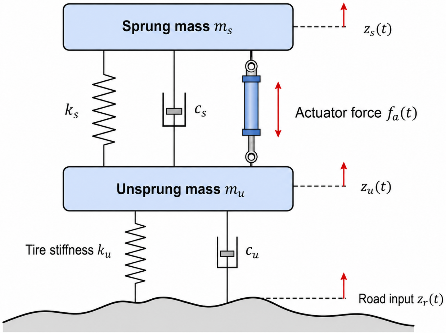
Consider a two-degree-of-freedom quarter-car active suspension system, as shown in Figure 1. Let z s ( t ) , z u ( t ) , and z r ( t ) denote the vertical displacements of the sprung mass, unsprung mass, and road profile, respectively. The sprung and unsprung masses are denoted by m s and m u . The suspension stiffness and damping coefficients are denoted by k s and c s , while the tire stiffness and damping coefficients are denoted by k u and c u . The actuator force applied between the sprung and unsprung masses is denoted by f a ( t ) .
The vertical dynamics are given by [9]
m s z ¨ s = c s ( z ˙ s z ˙ u ) k s ( z s z u ) + f a ,
m u z ¨ u = c s ( z ˙ s z ˙ u ) + k s ( z s z u ) c u ( z ˙ u z ˙ r ) k u ( z u z r ) f a .
For compactness, the time argument is omitted when no ambiguity arises.
Define the state variables as
χ 1 ( t ) = z s ( t ) z u ( t ) , χ 2 ( t ) = z ˙ s ( t ) , χ 3 ( t ) = z u ( t ) z r ( t ) , χ 4 ( t ) = z ˙ u ( t ) ,
where χ 1 ( t ) is the suspension deflection, χ 2 ( t ) is the sprung-mass velocity, χ 3 ( t ) is the tire deflection, and χ 4 ( t ) is the unsprung-mass velocity. Let χ ( t ) = col { χ 1 ( t ) , χ 2 ( t ) , χ 3 ( t ) , χ 4 ( t ) } and w r ( t ) = z ˙ r ( t ) , where w r ( t ) is the road velocity input.
From (1)–(2), one obtains
χ ˙ 1 ( t ) = χ 2 ( t ) χ 4 ( t ) , χ ˙ 2 ( t ) = k s m s χ 1 ( t ) c s m s χ 2 ( t ) + c s m s χ 4 ( t ) + 1 m s f a ( t ) , χ ˙ 3 ( t ) = χ 4 ( t ) w r ( t ) , χ ˙ 4 ( t ) = k s m u χ 1 ( t ) + c s m u χ 2 ( t ) k u m u χ 3 ( t ) c s + c u m u χ 4 ( t ) 1 m u f a ( t ) + c u m u w r ( t ) .
Thus, the original quarter-car model can be written as
χ ˙ ( t ) = A χ χ ( t ) + B f f a ( t ) + B r w r ( t ) ,
where
A χ = 0 1 0 1 k s m s c s m s 0 c s m s 0 0 0 1 k s m u c s m u k u m u c s + c u m u , B f = 0 1 m s 0 1 m u , B r = 0 0 1 c u m u .
Although (5) is a standard state-space representation, it does not explicitly distinguish the body-side dynamics from the wheel–actuator-side dynamics. For cascade controller design, the model is reorganized according to this physical separation.

2.3. Modified Cascade Decomposition

Define the primary and secondary subsystem states as
x 1 ( t ) = χ 1 ( t ) χ 2 ( t ) , x 2 ( t ) = χ 3 ( t ) χ 4 ( t ) f a ( t ) .
Here, x 1 ( t ) R 2 represents the body-side state, and x 2 ( t ) R 3 represents the wheel–actuator-side state.
To account for actuator dynamics, the actuator force is modeled as
f ˙ a ( t ) = 1 T a f a ( t ) + K a T a u 2 ( t ) ,
where T a > 0 is the actuator time constant, K a > 0 is the actuator gain, and u 2 ( t ) is the actuator command. This first-order model does not describe all hydraulic, electromagnetic, or electromechanical actuator nonlinearities, but it avoids the unrealistic assumption that the commanded force is applied instantaneously. In practical active suspensions, the control force may be generated by electro-hydraulic actuators or electromagnetic linear actuators; their bandwidth, force limit, and delay can affect the achieved control efficiency. These effects are therefore discussed and partially checked in the simulation section through actuator-effort, saturation, sensor-noise, and one-step-delay tests.
The primary subsystem is driven by the unsprung-mass velocity and the actuator force. Define the secondary output as
y 2 ( t ) = C 2 x 2 ( t ) = χ 4 ( t ) f a ( t ) , C 2 = 0 1 0 0 0 1 .
Then, the primary subsystem is written as
x ˙ 1 ( t ) = A 1 x 1 ( t ) + B 1 C 2 x 2 ( t ) ,
with
A 1 = 0 1 k s m s c s m s , B 1 = 1 0 c s m s 1 m s .
The secondary subsystem is
x ˙ 2 ( t ) = A 2 x 2 ( t ) + B 2 u 2 ( t ) + H 21 x 1 ( t ) + D 2 w r ( t ) ,
where
A 2 = 0 1 0 k u m u c s + c u m u 1 m u 0 0 1 T a , B 2 = 0 0 K a T a ,
and
H 21 = 0 0 k s m u c s m u 0 0 , D 2 = 1 c u m u 0 .
Combining (9) and (10), the active suspension system is rewritten as
x ˙ 1 ( t ) = A 1 x 1 ( t ) + B 1 C 2 x 2 ( t ) , x ˙ 2 ( t ) = A 2 x 2 ( t ) + B 2 u 2 ( t ) + H 21 x 1 ( t ) + D 2 w r ( t ) .
Remark 1.
The first equation in (11) is consistent with the usual cascade structure because the primary subsystem is driven by the secondary output. However, the second equation contains the coupling term H 21 x 1 ( t ) , which reflects the mechanical interaction from the sprung-mass motion to the unsprung-mass dynamics. Therefore, the active suspension is formulated as a modified cascade system rather than an ideal one-way cascade system. This distinction is central to the present formulation: the controller is synthesized on the coupled model rather than on a decoupled approximation.

2.4. Discrete-Time Modified Cascade Model

Let h > 0 be the sampling period. Under a zero-order-hold implementation, the control input and interconnection signals are represented by their sampled values over each sampling interval. Define x 1 ( k ) = x 1 ( k h ) , x 2 ( k ) = x 2 ( k h ) , and w r ( k ) = w r ( k h ) . The primary subsystem is discretized as
x 1 ( k + 1 ) = Φ 1 x 1 ( k ) + Γ 1 C 2 x 2 ( k ) ,
where
Φ 1 = e A 1 h , Γ 1 = 0 h e A 1 τ B 1 d τ .
The secondary subsystem is discretized as
x 2 ( k + 1 ) = Φ 2 x 2 ( k ) + Γ 2 u 2 ( k ) + H ¯ 21 x 1 ( k ) + D ¯ 2 w r ( k ) ,
where
Φ 2 = e A 2 h , Γ 2 = 0 h e A 2 τ B 2 d τ ,
and
H ¯ 21 = 0 h e A 2 τ H 21 d τ , D ¯ 2 = 0 h e A 2 τ D 2 d τ .
Thus, the discrete-time modified cascade model is
x 1 ( k + 1 ) = Φ 1 x 1 ( k ) + Γ 1 C 2 x 2 ( k ) , x 2 ( k + 1 ) = Φ 2 x 2 ( k ) + Γ 2 u 2 ( k ) + H ¯ 21 x 1 ( k ) + D ¯ 2 w r ( k ) .
For controller synthesis, the road disturbance is set to zero while the deterministic body–wheel coupling term H ¯ 21 x 1 ( k ) is retained. The nominal model is
x 1 ( k + 1 ) = Φ 1 x 1 ( k ) + Γ 1 C 2 x 2 ( k ) , x 2 ( k + 1 ) = Φ 2 x 2 ( k ) + Γ 2 u 2 ( k ) + H ¯ 21 x 1 ( k ) .

2.5. Discrete PI–P Cascade Controller

The controller contains a primary PI component and a secondary proportional component. The primary control signal is defined as
u 1 ( k ) = K p x 1 ( k ) + h K i j = 0 N x 1 ( k j ) ,
where K p and K i are the primary proportional and integral gains, respectively, and N + 1 is the finite memory length. Equivalently,
u 1 ( k ) = ( K p + h K i ) x 1 ( k ) + h K i j = 1 N x 1 ( k j ) .
The secondary controller is
u 2 ( k ) = u 1 ( k ) + K 2 x 2 ( k ) ,
where K 2 is the secondary proportional gain. Therefore,
u 2 ( k ) = ( K p + h K i ) x 1 ( k ) + h K i j = 1 N x 1 ( k j ) + K 2 x 2 ( k ) .
For the present active suspension system, K p R 1 × 2 , K i R 1 × 2 , and K 2 R 1 × 3 .
The finite-memory integral term is used to improve residual vibration attenuation while avoiding an infinitely growing integral state in the augmented representation. The memory length N therefore plays a practical role: a larger N approximates longer integral action but increases the augmented dimension, whereas a smaller N reduces computational burden but weakens low-frequency compensation.
Substituting (19) into (14) yields
x 1 ( k + 1 ) = Φ 1 x 1 ( k ) + Γ 1 C 2 x 2 ( k ) , x 2 ( k + 1 ) = H ¯ 21 + Γ 2 ( K p + h K i ) x 1 ( k ) + Γ 2 h K i j = 1 N x 1 ( k j ) + Φ 2 + Γ 2 K 2 x 2 ( k ) + D ¯ 2 w r ( k ) .
When w r ( k ) = 0 , the unforced closed-loop system becomes
x 1 ( k + 1 ) = Φ 1 x 1 ( k ) + Γ 1 C 2 x 2 ( k ) , x 2 ( k + 1 ) = H ¯ 21 + Γ 2 ( K p + h K i ) x 1 ( k ) + Γ 2 h K i j = 1 N x 1 ( k j ) + Φ 2 + Γ 2 K 2 x 2 ( k ) .

2.6. Controlled Outputs and Design Objective

The controlled outputs are selected according to ride comfort, suspension travel, and road-holding requirements. The sprung-mass acceleration is
a s ( k ) = k s m s χ 1 ( k ) c s m s χ 2 ( k ) + c s m s χ 4 ( k ) + 1 m s f a ( k ) .
Using x 1 ( k ) and x 2 ( k ) , it can be written as
a s ( k ) = C a 1 x 1 ( k ) + C a 2 x 2 ( k ) ,
where
C a 1 = k s m s c s m s , C a 2 = 0 c s m s 1 m s .
The normalized suspension deflection and tire-load-related output are defined as
z d ( k ) = χ 1 ( k ) z max , z t ( k ) = k u χ 3 ( k ) ( m s + m u ) g ,
where z max > 0 is the admissible suspension travel and g is the gravitational acceleration. The corresponding constraints are | z d ( k ) | 1 and | z t ( k ) | 1 . The regulated output is selected as
z ( k ) = col { a s ( k ) , z d ( k ) , z t ( k ) } .
These outputs correspond to the standard quarter-car objectives of ride comfort, suspension working space, and vertical tire-load-related response. They do not represent lateral handling, yaw stability, pitch attitude, or roll stability. This output selection is therefore consistent with the stated quarter-car modeling scope.
The design objective is to determine K p , K i , and K 2 such that the unforced closed-loop system (21) is asymptotically stable. When road disturbance is considered, the induced response from w r ( k ) to z ( k ) should be attenuated while keeping the suspension deflection and tire-load-related output within admissible ranges. In addition, the actuator force and command should remain within a range compatible with practical active suspension hardware. Since hard saturation is not included directly in the present LMI synthesis, actuator feasibility is evaluated through the time response, peak value, and RMS control effort in the simulation section.

3. Stability Analysis

This section establishes stability conditions for the modified cascade active suspension system. Since the coupling term from the primary subsystem to the secondary subsystem is retained, the stability analysis is conducted for the modified cascade closed-loop model rather than for an ideal feedforward cascade approximation.

3.1. Augmented System Representation

Define the augmented vector
ξ ( k ) = col x 1 ( k ) , x 1 ( k 1 ) , , x 1 ( k N ) , x 2 ( k ) .
Let S 0 , S 1 , , S N and S a be selection matrices satisfying
x 1 ( k j ) = S j ξ ( k ) , j = 0 , 1 , , N , x 2 ( k ) = S a ξ ( k ) .
Define F 12 = Γ 1 C 2 . Then,
x 1 ( k + 1 ) = M 1 ξ ( k ) , M 1 = Φ 1 S 0 + F 12 S a .
The secondary subsystem update in (21) is written as
x 2 ( k + 1 ) = M 2 ξ ( k ) ,
where
M 2 = H ¯ 21 + Γ 2 ( K p + h K i ) S 0 + j = 1 N Γ 2 h K i S j + Φ 2 + Γ 2 K 2 S a .
Define the forward difference of the primary state as δ 1 ( k ) = x 1 ( k + 1 ) x 1 ( k ) . Using (28),
δ 1 ( k ) = Δ 0 ξ ( k ) , Δ 0 = M 1 S 0 .
For the delayed primary states, define
Δ j = S j 1 S j , j = 1 , 2 , , N .
Then x 1 ( k j + 1 ) x 1 ( k j ) = Δ j ξ ( k ) for j = 1 , , N .

3.2. Lyapunov Functional

To capture the finite-memory PI action and the secondary dynamics, consider
V ( k ) = V 1 ( k ) + V 2 ( k ) + V 3 ( k ) + V 4 ( k ) ,
where
V 1 ( k ) = x 1 T ( k ) P x 1 ( k ) , V 2 ( k ) = i = 1 N s = k i k 1 x 1 T ( s ) Q i x 1 ( s ) , V 3 ( k ) = i = 1 N θ = i 1 s = k + θ k 1 δ 1 T ( s ) R i δ 1 ( s ) , V 4 ( k ) = x 2 T ( k ) T x 2 ( k ) .
Here, P = P T 0 , T = T T 0 , Q i = Q i T 0 , and R i = R i T 0 . The term V 2 ( k ) reflects the finite memory associated with the primary PI controller, while V 3 ( k ) penalizes the variation of the primary state within the same memory window.

3.3. Stability Criterion for Given PI–P Gains

Theorem 1.
Consider the unforced modified cascade closed-loop system (21). For given controller gains K p , K i , and K 2 , suppose that there exist matrices P 0 , T 0 , Q i 0 , and R i 0 , i = 1 , , N , such that
Ω 0 ,
where
Ω = M 1 T P M 1 S 0 T P S 0 + S 0 T i = 1 N Q i S 0 i = 1 N S i T Q i S i + i = 1 N i Δ 0 T R i Δ 0 i = 1 N j = 1 i Δ j T R i Δ j + M 2 T T M 2 S a T T S a .
Then the origin of (21) is asymptotically stable.
Proof. 
The difference of V 1 ( k ) is
Δ V 1 ( k ) = ξ T ( k ) M 1 T P M 1 S 0 T P S 0 ξ ( k ) .
For V 2 ( k ) , one has
Δ V 2 ( k ) = ξ T ( k ) S 0 T i = 1 N Q i S 0 i = 1 N S i T Q i S i ξ ( k ) .
Using δ 1 ( k ) = Δ 0 ξ ( k ) and Δ j = S j 1 S j , the difference of V 3 ( k ) is
Δ V 3 ( k ) = ξ T ( k ) i = 1 N i Δ 0 T R i Δ 0 i = 1 N j = 1 i Δ j T R i Δ j ξ ( k ) .
Similarly,
Δ V 4 ( k ) = ξ T ( k ) M 2 T T M 2 S a T T S a ξ ( k ) .
Combining the four terms yields Δ V ( k ) = ξ T ( k ) Ω ξ ( k ) . If (35) holds, then Δ V ( k ) < 0 for all ξ ( k ) 0 . Hence, the unforced closed-loop system is asymptotically stable. This completes the proof. □
Remark 2.
Theorem 1 is a structure-preserving stability verification result for given PI–P gains. The coupling matrix H ¯ 21 is included in M 2 , so the condition is derived for the modified cascade active suspension model instead of an idealized cascade approximation.

3.4. LMI-Based PI–P Controller Synthesis

The condition (35) is useful for verification but is not directly convenient for controller synthesis because M 2 contains products between the controller gains and the Lyapunov matrix T. To obtain a tractable sufficient synthesis condition, define the augmented open-loop system
ξ ( k + 1 ) = A 0 ξ ( k ) + B 0 u 2 ( k ) ,
where
A 0 = Φ 1 0 0 Γ 1 C 2 I 0 0 0 0 I 0 0 0 0 I 0 H ¯ 21 0 0 Φ 2 , B 0 = 0 0 0 Γ 2 .
The PI–P controller is written as
u 2 ( k ) = K ξ ( k ) , K = K p + h K i h K i h K i K 2 .
Therefore,
ξ ( k + 1 ) = A 0 + B 0 K ξ ( k ) .
Theorem 2.
Consider (40). If there exist symmetric positive definite matrices X 1 = X 1 T 0 , X 2 = X 2 T 0 , and matrices Y p R 1 × 2 , Y i R 1 × 2 , and Y 2 R 1 × 3 such that
X A 0 X + B 0 Y T A 0 X + B 0 Y X 0 ,
where
X = diag X 1 , , X 1 N + 1 blocks , X 2 , Y = Y p + h Y i h Y i h Y i Y 2 ,
then (40) is asymptotically stable. Moreover, the controller gains are recovered by
K p = Y p X 1 1 , K i = Y i X 1 1 , K 2 = Y 2 X 2 1 .
Proof. 
Let P = X 1 . The discrete-time Lyapunov inequality
A 0 + B 0 K T P A 0 + B 0 K P 0
guarantees asymptotic stability. By the Schur complement, it is equivalent to
X A 0 + B 0 K X T A 0 + B 0 K X X 0 .
Since K X = Y , the above inequality becomes (41). Therefore, if (41) is feasible, the closed-loop system is asymptotically stable, and the gains are given by (42). This completes the proof. □
Remark 3.
Theorem 2 provides a tractable sufficient LMI synthesis condition for the modified cascade active suspension system. The use of the repeated block X 1 preserves the structure of the PI memory terms and enables the proportional, integral, and secondary gains to be recovered from linear matrix variables. Unlike MPC, the resulting controller does not require online optimization once the gains are obtained. This makes the method suitable for low-complexity sampled-data implementation, although it also means that hard input and state constraints are not handled as explicitly as in constrained predictive control.

3.5. Road-Disturbance Performance Analysis

After the controller gains are obtained, the road disturbance can be included in the augmented dynamics:
ξ ( k + 1 ) = A c ξ ( k ) + D r w r ( k ) ,
where
A c = A 0 + B 0 K , D r = col 0 , , 0 , D ¯ 2 .
The regulated output can be written as
z ( k ) = C z ξ ( k ) ,
where
C z = C a 1 0 0 C a 2 C d 1 0 0 0 0 0 0 C t 2 ,
with
C d 1 = 1 z max 0 , C t 2 = k u ( m s + m u ) g 0 0 .
For a prescribed scalar γ > 0 , the following condition gives a post-design disturbance attenuation certificate:
A c T P A c P + C z T C z A c T P D r D r T P A c D r T P D r γ 2 I 0 .
If (46) holds, then under zero initial conditions,
k = 0 z T ( k ) z ( k ) < γ 2 k = 0 w r T ( k ) w r ( k ) .
Remark 4.
The condition (46) is used to evaluate the response from road excitation to the regulated suspension output after the PI–P gains have been obtained. If this performance requirement is to be imposed during controller synthesis, additional variable transformations are needed to handle the products between A c and P .

3.6. Design Procedure

The proposed design procedure is summarized as follows.
1.
Establish the quarter-car active suspension model and rewrite it as the modified cascade system (11).
2.
Select the sampling period h and the PI memory length N.
3.
Compute Φ 1 , Γ 1 , Φ 2 , Γ 2 , H ¯ 21 , and D ¯ 2 .
4.
Construct A 0 and B 0 according to (38).
5.
Solve the LMI (41) and recover K p , K i , and K 2 from (42).
6.
Substitute the obtained gains into M 1 and M 2 , and verify the structure-preserving condition (35).
7.
Evaluate the road-disturbance attenuation property through (46).
This procedure avoids forcing the active suspension into an ideal cascade form. Instead, the body–wheel coupling is retained in the secondary subsystem, and the PI–P controller is synthesized for the resulting modified cascade sampled-data model.
Remark 5.
The proposed PI–P law should be interpreted as a structured cascade controller rather than as a generic empirical PID variant. The primary PI component is assigned to the body-side state because sprung-mass motion is directly related to ride comfort, while the secondary proportional component acts on the wheel–actuator-side state because this channel influences tire deflection, unsprung-mass motion, and actuator force. This physical assignment, together with finite-memory sampled-data implementation and LMI-based gain co-design, distinguishes the method from simple trial-and-error PID tuning. In the numerical validation, the secondary proportional controller is used as an ablation baseline, while skyhook control and LQR control are used as representative active-suspension benchmarks. The manuscript therefore does not claim a numerical comparison with all advanced active-suspension controllers. Since practical active suspensions may use electro-hydraulic actuators or electromagnetic linear actuators, actuator bandwidth, force limits, and delay can affect the achieved control efficiency. These implementation issues are not embedded directly in the synthesis LMI, but they are examined numerically through actuator-effort, saturation, sensor-noise, and one-step-delay checks. Finally, the quarter-car model is suitable for vertical ride comfort analysis, but it cannot evaluate pitch, roll, load transfer, or lateral handling; these effects require half-car or full-car validation and are left for future work.

4. Simulation Results

4.1. Simulation Setup

To evaluate the effectiveness of the proposed discrete PI–P cascade controller, numerical simulations are conducted on the quarter-car active suspension system described in Section 2.2. The simulation adopts the modified cascade representation developed in Section 2.3, where x 1 = col { χ 1 , χ 2 } denotes the body-side state and x 2 = col { χ 3 , χ 4 , f a } denotes the wheel–actuator-side state. The main responses examined in the simulation are the sprung-mass acceleration a s , suspension deflection χ 1 , tire-load-related output z t , actuator force f a , and actuator command u 2 . In this quarter-car setting, a s is used as the main ride comfort indicator, χ 1 reflects the suspension working space, z t is used as a vertical road-holding-related indicator, and f a and u 2 are used to evaluate actuator effort.
The present paper is mainly a theoretical controller-synthesis study. Therefore, the validation is conducted through numerical simulations and implementation-oriented checks rather than physical bench or road tests. To address the limitation of the original validation, the revised simulation section adds skyhook and LQR active-suspension benchmarks, random-road excitation, multiple vehicle speeds, quantitative RMS and peak indices, actuator-saturation checks, sensor-noise tests, and one-step input-delay tests. These additions are intended to strengthen the numerical evidence while keeping the scope consistent with a quarter-car theoretical study.
The main physical and simulation parameters are listed in Table 1. The suspension parameters correspond to a typical quarter-car active suspension configuration, while the actuator is modeled as a first-order dynamic system. The sampling period is selected as h = 0.002 s , and the simulation horizon is set to 12 s . The finite-memory length of the primary PI component is chosen as N = 8 . The baseline road excitation is constructed as a unified disturbance composed of a short half-sine bump and a decaying low-frequency component. The bump has a height of 0.04 m , a length of 5 m , and is crossed at a vehicle speed of 20 m / s . The decaying low-frequency component is introduced after the bump to examine the suspension response during both transient excitation and post-disturbance attenuation. Consistent with the state-space formulation, the road velocity w r = z ˙ r is used as the external disturbance input.
The simulation evaluation is organized in two stages. First, a baseline comparison is conducted among the passive suspension, the secondary proportional controller, and the proposed PI–P controller under the bump–low-frequency road input. The passive suspension is used as the mechanical reference case, where the actuator command is set to zero. The secondary proportional controller only uses the wheel–actuator-side feedback u 2 ( k ) = K 2 x 2 ( k ) and is therefore treated as an ablation case. It helps reveal the effect of removing the primary body-side PI loop while retaining the secondary feedback channel. The proposed PI–P controller combines the body-side PI regulation and the secondary proportional feedback as
u 2 ( k ) = ( K p + h K i ) x 1 ( k ) + h K i j = 1 N x 1 ( k j ) + K 2 x 2 ( k ) .
The controller gains are obtained by solving the LMI synthesis condition given in Theorem 2. The resulting gains used in the simulation are K p = [ 4.910344 × 10 3 , 3.327517 × 10 3 ] , K i = [ 9.369910 × 10 2 , 1.619339 × 10 1 ] , and K 2 = [ 4.696728 × 10 4 , 9.377497 × 10 2 , 1.851170 × 10 2 ] . For all simulations, the initial suspension states are set to zero.
Second, an extended validation is conducted to provide a broader performance assessment. In addition to the passive suspension, the secondary proportional ablation case, and the proposed PI–P controller, skyhook control and LQR control are introduced as representative active-suspension benchmark methods. The extended validation also includes a random-road case, multiple vehicle speeds, actuator-saturation checks, and sensor-noise/input-delay checks. This organization allows the proposed method to be assessed not only through time-domain curves but also through quantitative RMS and peak performance indices. The added baselines and road cases directly address the concern that the original manuscript relied on a small number of curves from a single simulation scenario.
For fairness, the skyhook and LQR baselines are implemented using the same quarter-car model, sampling period, actuator model, road inputs, and initial conditions as the proposed PI–P controller. The skyhook controller is selected as a physically interpretable damping benchmark, with the damping coefficient set to c sky = 1800 N s / m . This value was chosen to provide clear sprung-mass vibration attenuation without producing an excessively large actuator command. The LQR controller is designed from the same five-state discrete quarter-car model, with the quadratic cost
J LQR = k = 0 x ( k ) T Q LQR x ( k ) + R LQR u 2 2 ( k ) ,
where Q LQR = diag { 8 × 10 5 , 1.5 × 10 3 , 1.0 × 10 5 , 5 × 10 2 , 1 × 10 4 } , R LQR = 5 × 10 4 . The weighting matrix penalizes the suspension deflection, body-side velocity, tire-side displacement, tire-side velocity, and actuator force state, while the input weight limits excessive actuator command. The weights were selected by trial tuning to obtain a stable and competitive comfort-oriented active-suspension benchmark with reasonable actuator effort. Therefore, the skyhook and LQR controllers are not intentionally under-tuned references; rather, they are representative low-complexity and optimal-control baselines used to contextualize the performance of the proposed PI–P controller.

4.2. Baseline Responses Under the Bump–Low-Frequency Road Input

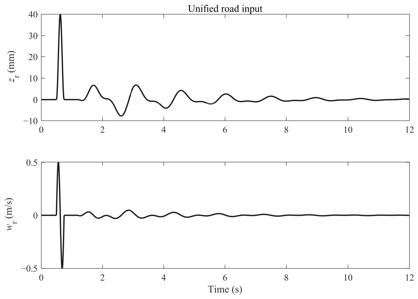
The unified road excitation in Figure 2 defines the external disturbance environment used to evaluate the baseline closed-loop suspension responses. The road displacement z r consists of a short half-sine bump followed by a decaying low-frequency component. The half-sine bump introduces an abrupt transient excitation, which is used to test the immediate vibration attenuation capability of different suspension strategies. The decaying low-frequency component provides a smoother and gradually vanishing disturbance, allowing the post-disturbance convergence behavior to be observed after the main excitation has passed. As shown in the figure, the road excitation is mainly concentrated in the early stage and then attenuates gradually. This excitation profile therefore provides a unified scenario for evaluating both transient suppression and convergence performance.
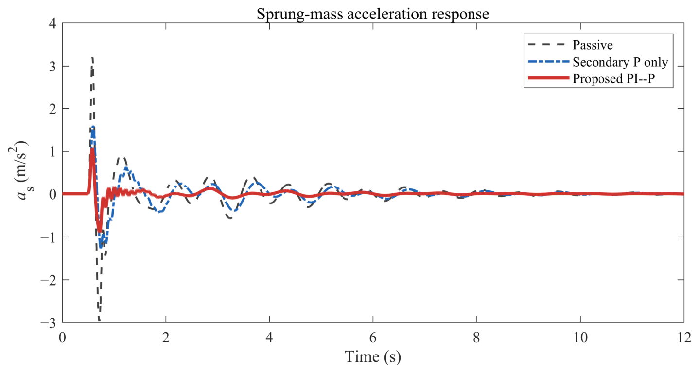
The sprung-mass acceleration response in Figure 3 directly reflects the ride comfort performance of the three baseline strategies under the unified disturbance. Under the road excitation, the passive suspension exhibits the largest acceleration fluctuation, indicating that the road-induced vibration is transmitted to the vehicle body with limited attenuation. The secondary proportional controller reduces the acceleration response to some extent, showing that wheel–actuator-side feedback can improve the dynamic behavior of the suspension. However, its attenuation capability remains limited because it does not directly regulate the body-side state. In comparison, the proposed PI–P controller produces the smallest acceleration fluctuation amplitude among the three cases. After the road excitation decays, all three responses gradually approach zero, while the proposed PI–P controller exhibits the weakest residual oscillation. This confirms the advantage of introducing body-side PI regulation into the modified cascade structure for ride comfort improvement.
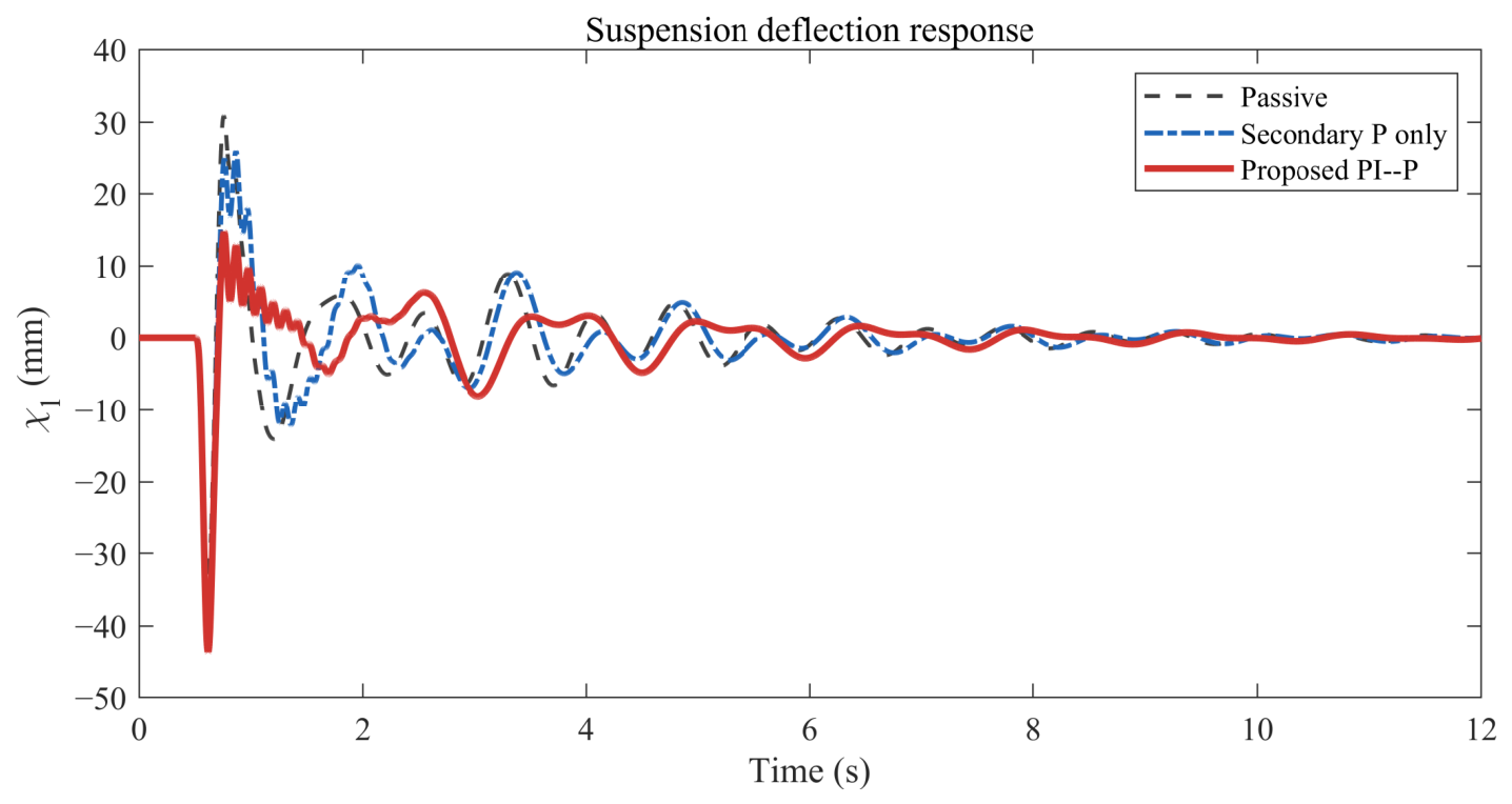
The suspension deflection response in Figure 4 is used to examine whether the improvement in body vibration is achieved while maintaining acceptable suspension travel. The suspension deflection χ 1 reflects the relative displacement between the sprung and unsprung masses and is therefore an important indicator of the suspension working range. The proposed PI–P controller yields a smaller and more convergent response than the passive suspension and the secondary proportional controller in this baseline comparison, demonstrating that the body–wheel relative motion is more effectively regulated under the proposed control structure. This observation further supports the necessity of introducing body-side regulation into the controller. As the road disturbance gradually vanishes, the suspension deflection responses of all three cases decay to zero, which is consistent with the closed-loop stability property established in the theoretical analysis.
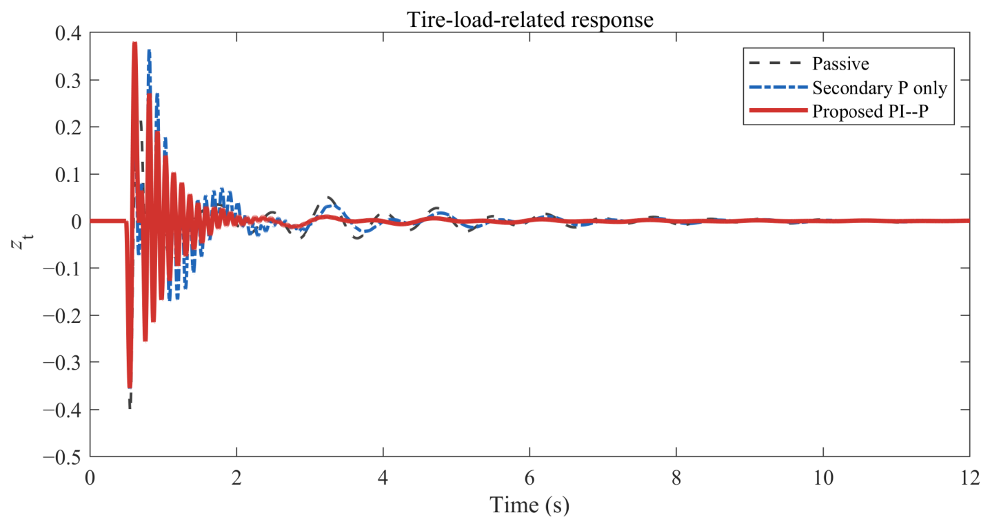
The tire-load-related response in Figure 5 further evaluates the influence of the controller on the vertical road-holding-related behavior. The output z t is associated with tire deflection and reflects the variation of the tire-load-related response under road excitation. At the beginning of the excitation, the proposed PI–P controller shows a fluctuation level comparable to those of the passive suspension and the secondary proportional controller. In some short intervals, the tire-load-related response under the proposed controller is slightly larger. This phenomenon is reasonable because the controller actively redistributes the transient suspension response in order to suppress the body-side vibration more effectively. After the main excitation interval, however, the proposed PI–P controller exhibits a clear convergence tendency. This result indicates that the improvement in ride comfort is not accompanied by persistent deterioration of the vertical road-holding-related response. Since quarter-car tire deflection is only a vertical road-holding-related indicator, this result should not be interpreted as a complete handling evaluation.
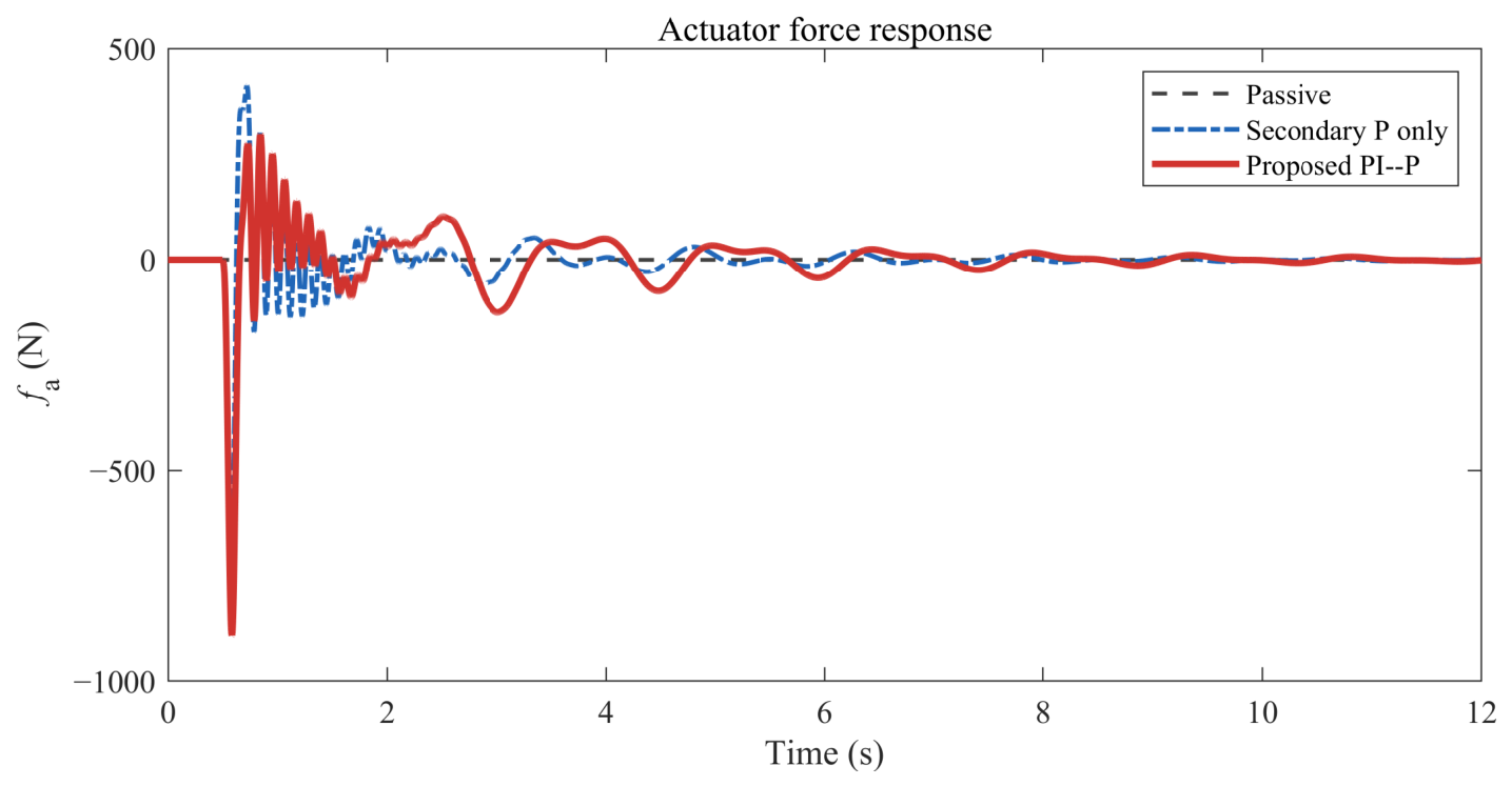
The actuator force response in Figure 6 illustrates the physical control effort required to achieve the observed vibration attenuation. Around the bump disturbance, the proposed PI–P controller generates a relatively large actuator force to counteract the abrupt road excitation, which is consistent with the stronger reduction in sprung-mass acceleration shown in Figure 3. Compared with the passive suspension and the secondary proportional controller, the proposed controller generally requires a larger actuator force during the initial transient stage. This is expected because the proposed PI–P controller combines body-side PI regulation with secondary-side proportional feedback and therefore applies a more active corrective action to suppress body vibration.
After the main excitation interval, the actuator force decreases rapidly and approaches zero as the road disturbance attenuates. The bounded and vanishing behavior of f a indicates that the improved vibration attenuation is achieved without persistent actuator effort. Since the actuator is modeled as a first-order system with a small time constant and unit gain, the actuator force can closely track the controller command u 2 . Therefore, the command response is not plotted separately in this baseline case to avoid redundant time-domain information. This also clarifies why the original actuator-force and actuator-command figures showed very similar trends: under the adopted first-order actuator model, the actual force follows the command rapidly.
Overall, the baseline simulation results demonstrate that the proposed PI–P controller provides effective attenuation of the sprung-mass acceleration and supports better post-disturbance convergence compared with the passive suspension and the secondary proportional ablation case. The secondary proportional controller improves the response relative to the passive suspension, but its performance is limited because it only acts through the wheel–actuator-side dynamics and does not directly regulate the body-side state. By incorporating primary PI regulation into the modified cascade framework, the proposed controller achieves stronger body-side vibration suppression. Although this improvement requires a relatively larger actuator force and command during the initial excitation interval, both f a and u 2 remain bounded and decay to zero after the road disturbance vanishes.

4.3. Extended Validation with Additional Baselines and Road Conditions

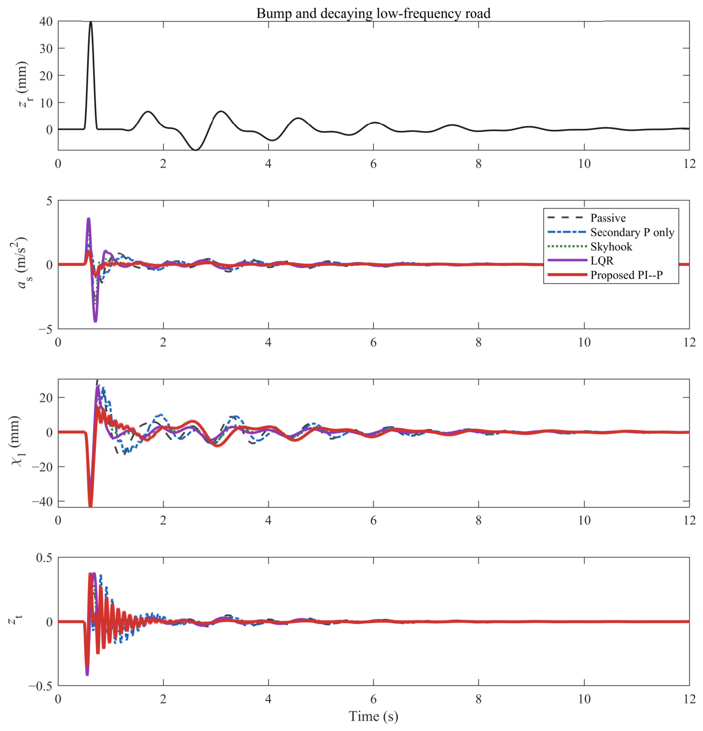
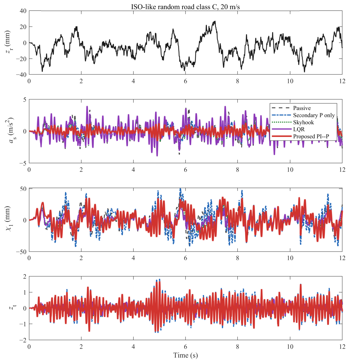
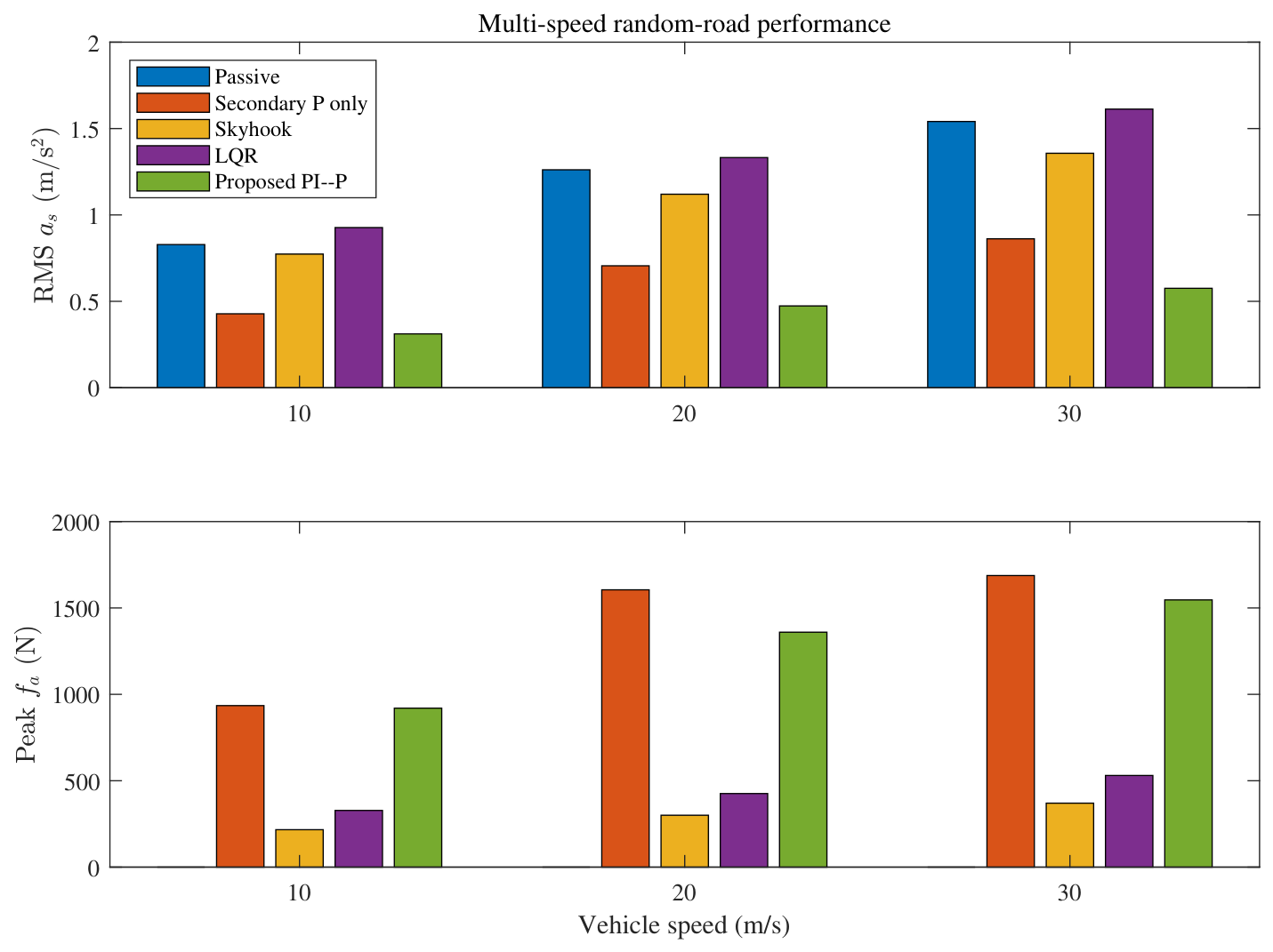
To further strengthen the validation, additional simulations are conducted by introducing skyhook and LQR active-suspension benchmarks, quantitative performance indices, random-road excitation, multiple vehicle speeds, implementation-related checks, critical trade-off interpretation, and finite-memory-length sensitivity analysis. In addition to the passive suspension and the secondary proportional controller, skyhook control and LQR control are included as representative active-suspension baselines. The secondary proportional controller is retained as an ablation case because it removes the primary body-side PI loop while preserving the wheel–actuator-side feedback channel. All controllers are evaluated under the same vehicle parameters, road inputs, sampling period, and actuator model. The extended validation includes four figures and six tables: Figure 7 and Figure 8, together with Table 2, examine the bump–low-frequency road case; Figure 9 and Table 3 evaluate the random-road case at 20 m / s ; Figure 10 and Table 4 examine speed-dependent random-road behavior; Table 5 reports the actuator-saturation, sensor-noise, and input-delay checks; Table 6 summarizes the comfort–safety–actuator-effort trade-off of the proposed method; and Table 7 reports the sensitivity of the proposed controller to the finite-memory length N.
Figure 7 compares the main suspension responses under the bump–low-frequency road input, including the road displacement, sprung-mass acceleration, suspension deflection, and tire-load-related output. The proposed PI–P controller provides the most effective suppression of sprung-mass acceleration among the compared methods, and the acceleration response returns closest to zero after the road disturbance. In contrast, the LQR controller exhibits the largest acceleration fluctuation in this case, while the passive suspension, secondary proportional controller, and skyhook controller show relatively similar oscillatory levels. For the suspension deflection χ 1 , the proposed controller shows a clear convergence tendency after the main excitation, although its peak value is not the smallest. For the tire-load-related output z t , the responses of different controllers are close to each other, indicating that the improvement in ride comfort is not accompanied by pronounced deterioration in the vertical road-holding-related indicator.
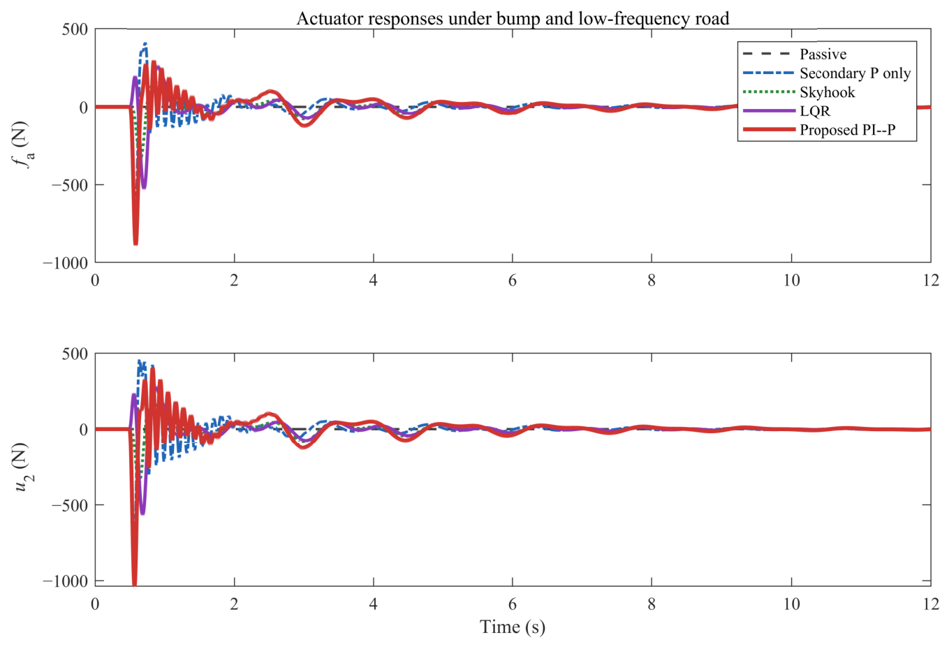
Figure 8 shows the actuator force f a and actuator command u 2 under the bump–low-frequency road input. For all active controllers, both responses exhibit transient fluctuations near the road disturbance and then gradually converge to zero. The proposed PI–P controller requires a relatively stronger transient actuator effort than skyhook and LQR control, which is consistent with its stronger attenuation of sprung-mass acceleration. However, the actuator force and command remain bounded and vanish after the road disturbance attenuates, indicating that the improved ride comfort performance is achieved without persistent actuator effort.
Figure 9 presents the responses under the random road input at 20 m / s . Compared with the bump–low-frequency input, the random road produces more continuous fluctuations and therefore provides a broader excitation scenario. For the sprung-mass acceleration a s , the proposed PI–P controller gives the smallest fluctuation around zero, while the LQR controller shows the largest response in this case. The passive suspension, secondary proportional controller, and skyhook controller exhibit relatively close acceleration levels. For the suspension deflection χ 1 and the tire-load-related output z t , the responses of different controllers remain comparable in magnitude, with no severe deterioration caused by the proposed method. These results further show that the proposed controller improves ride comfort-related acceleration performance while maintaining acceptable suspension-deflection and vertical road-holding-related behavior.
Figure 10 compares the random-road performance at 10 m / s , 20 m / s , and 30 m / s . In terms of RMS sprung-mass acceleration, the proposed PI–P controller consistently gives the smallest value at all three speeds, followed by the secondary proportional controller. The skyhook and passive suspension show larger RMS acceleration, while the LQR controller gives the largest RMS value in the tested cases. In terms of peak actuator force, the secondary proportional controller requires the largest force, the proposed PI–P controller ranks second, the LQR controller follows, and the skyhook controller requires the smallest force. This result indicates that the ride comfort improvement of the proposed method is accompanied by higher actuator-effort demand than skyhook and LQR control, but its required force remains lower than that of the secondary proportional controller.
Table 2 summarizes the quantitative comparison under the bump–low-frequency road input at 20 m / s . The proposed PI–P controller achieves the lowest RMS and peak sprung-mass acceleration among all compared methods. The RMS acceleration is reduced from 3.8506 × 10 1 for the passive suspension to 1.0718 × 10 1 , corresponding to a reduction of about 72.2 % . Compared with the secondary proportional controller, skyhook controller, and LQR controller, the RMS acceleration reductions are about 53.2 % , 66.1 % , and 76.1 % , respectively. The proposed controller also reduces the peak acceleration from 3.2061 m / s 2 for the passive suspension to 1.0796 m / s 2 . For the remaining indices, the proposed method shows a clear comfort-oriented trade-off: its RMS suspension deflection is lower than those of the passive suspension and the secondary proportional controller, but higher than those of skyhook and LQR control; its peak suspension deflection and actuator effort are relatively larger. Therefore, the proposed method provides the strongest body-acceleration attenuation in this case, at the cost of increased transient actuator effort.
Table 3 reports the quantitative comparison under the random road input at 20 m / s . The proposed PI–P controller again achieves the lowest RMS and peak sprung-mass acceleration. Its RMS acceleration is 4.7337 × 10 1 , giving reductions of about 62.5 % , 32.9 % , 57.7 % , and 64.5 % compared with the passive suspension, secondary proportional controller, skyhook controller, and LQR controller, respectively. The peak acceleration is reduced from 3.9353 m / s 2 for the passive suspension to 1.5422 m / s 2 , corresponding to a reduction of about 60.8 % . For suspension deflection and tire-load-related response, skyhook and LQR control show smaller values in some indices, which reflects their different design emphasis. The proposed method therefore provides the strongest ride comfort improvement under this random-road case, while its suspension-travel, tire-load-related response, and actuator effort remain within a reasonable comfort-oriented trade-off range.
Table 4 summarizes the speed-dependent quantitative comparison under the random road input. At 10 m / s , 20 m / s , and 30 m / s , the proposed PI–P controller consistently achieves the lowest RMS and peak sprung-mass acceleration among the compared methods. Compared with the passive suspension, the RMS acceleration reductions are about 62.4 % , 62.5 % , and 62.7 % , respectively. Compared with the secondary proportional controller, the corresponding reductions are about 27.2 % , 32.9 % , and 33.2 % . At 30 m / s , for example, the RMS acceleration of the proposed method is 5.7546 × 10 1 , while those of skyhook and LQR control are 1.3569 and 1.6126 , respectively. The proposed controller requires larger peak actuator force than skyhook and LQR control, especially at higher speeds, but its force demand remains below that of the secondary proportional controller. These results confirm that the proposed PI–P controller maintains its ride comfort advantage over the tested speed range, with a clear actuator-effort trade-off.
Table 5 provides implementation-oriented checks for the proposed PI–P controller under actuator saturation, sensor noise, and one-step input delay. The actuator-saturation results show that the unsaturated actuator command does not exceed the tested saturation limits from 1500 N to 3500 N under the bump–low-frequency road input; the saturation rate therefore remains zero, and the saturated and unsaturated responses are identical in the tested cases. In particular, the peak actuator command is 1037.09 N , which is below the smallest tested saturation limit of 1500 N . With sensor noise, the RMS sprung-mass acceleration changes from 1.0718 × 10 1 to 1.0858 × 10 1 , corresponding to an increase of about 1.3 % . With one-step delay and with combined noise and delay, the RMS acceleration remains at a comparable level. The peak actuator force and command increase only mildly, and no saturation is triggered. These results do not constitute a complete robustness proof, but they indicate that the proposed sampled-data PI–P controller is not highly sensitive to the tested levels of measurement noise and one-step input delay.
It should also be noted that the saturation check in Table 6 only verifies the tested saturation range under the bump–low-frequency road input. If the admissible actuator-command bound is tighter than the tested range, the command ( u 2 ) would be clipped before reaching the value required by the nominal PI–P law. In that case, the effective actuator force would be reduced, and the closed-loop response would no longer exactly follow the linear sampled-data model used in the LMI synthesis. The expected consequence is a degradation of the acceleration-attenuation performance, especially during transient road excitation, and the response would move closer to that of a weaker active controller. Therefore, the proposed controller should be used with sufficient actuator authority, or combined with anti-windup compensation and saturation-aware gain synthesis when a tighter actuator limit is imposed.
The above comparisons also clarify the recommendation boundary of the proposed PI–P controller. The method is not intended to be a universally best solution for all suspension criteria. Its main advantage lies in ride comfort improvement, as it achieves the lowest RMS and peak sprung-mass acceleration among the tested controllers. Therefore, it is recommended when vertical comfort is the dominant design objective and sufficient actuator authority is available. However, this comfort benefit is obtained with higher transient actuator force and command than skyhook and LQR control, indicating a higher energy-related demand. In addition, the proposed controller does not always provide the smallest suspension deflection or tire-load-related response. Thus, when actuator energy consumption or tire-contact safety is assigned the highest priority, skyhook, LQR, or a reweighted PI–P design with explicit actuator-effort and tire-load constraints may be more appropriate.
To justify the selected finite-memory length, a short sensitivity analysis with respect to N is further conducted under the bump–low-frequency road input. Since the augmented vector is defined as ξ ( k ) = col { x 1 ( k ) , x 1 ( k 1 ) , , x 1 ( k N ) , x 2 ( k ) } , with x 1 R 2 and x 2 R 3 , the augmented dimension is n ξ = 2 ( N + 1 ) + 3 = 2 N + 5 . Therefore, increasing N directly increases the dimension of the augmented system and the corresponding LMI size. Table 7 shows that the closed-loop response is only weakly affected by N in the tested range. When N increases from 2 to 12, the RMS and peak sprung-mass acceleration change only slightly, while the peak suspension deflection and peak actuator command also vary within a very narrow range. In contrast, the augmented dimension increases linearly from 9 to 29. Therefore, increasing N does not bring a meaningful performance improvement in this case, but it increases the dimension of the LMI synthesis problem. The value N = 8 is thus adopted as a moderate setting that keeps the finite-memory PI structure while avoiding an unnecessarily large augmented system.
Overall, the extended simulations provide a more complete assessment of the proposed method. The inclusion of skyhook and LQR control strengthens the benchmark comparison beyond the passive suspension and the secondary proportional ablation baseline. Compared with all listed methods, the proposed PI–P controller achieves the strongest reduction in sprung-mass acceleration under both bump and random-road excitations, and this advantage is maintained over the tested speed range. The results also clarify the main trade-off: the proposed controller requires higher transient actuator effort and does not always give the smallest suspension deflection or tire-load-related response. Nevertheless, for the present ride comfort-oriented quarter-car study, the actuator command remains below the tested saturation limits, and the additional noise and delay checks support the numerical feasibility of the proposed sampled-data controller.


5. Conclusions

This paper developed an LMI-based discrete PI–P cascade control method for active vehicle suspension systems. The study is positioned at the quarter-car level and focuses on vertical ride comfort-oriented control, so the conclusions concern sprung-mass acceleration, suspension travel, tire-load-related vertical response, and actuator effort, rather than full-vehicle handling, pitch, or roll performance. The quarter-car dynamics were reformulated as a modified cascade sampled-data system, where the body-side and wheel–actuator-side dynamics were separated while the body–wheel coupling was retained. Based on this structure, a discrete PI–P controller was designed, and a Lyapunov-based stability condition together with an LMI synthesis method was established for gain co-design. The contribution is therefore not the use of the PI–P idea alone, but its integration with the modified cascade representation, finite-memory sampled-data PI action, secondary wheel–actuator-side proportional feedback, and LMI-based synthesis. Simulation results show that the proposed controller achieves stronger sprung-mass acceleration attenuation than the passive suspension, the secondary proportional ablation controller, skyhook control, and LQR control under the considered road excitations. Additional random-road, multi-speed, actuator-saturation, sensor-noise, and one-step-delay checks further support the numerical effectiveness and implementation feasibility of the proposed method.
The results also clarify the recommendation boundary of the proposed method. The PI–P controller is suitable for comfort-prioritized active suspension control because it provides the strongest reduction in RMS and peak sprung-mass acceleration among the tested methods. However, it should not be regarded as a universally best solution. The improved comfort is obtained with higher transient actuator effort, and the controller does not always give the smallest suspension deflection or tire-load-related response. Therefore, when actuator energy consumption or tire-contact safety is the dominant objective, skyhook, LQR, or a reweighted PI–P design with explicit energy and tire-load constraints may be more appropriate.
This work remains a theoretical and numerical study, and physical bench or road experiments are not included. This is a limitation of the present work, because simulations cannot fully represent practical actuator nonlinearities, installation effects, sensor imperfections, and real road disturbances. Future work will focus on experimental validation with practical active-suspension actuators, such as electro-hydraulic or electromagnetic linear actuators, and on extending the method to half-car and full-car models to evaluate pitch, roll, load transfer, and handling-related performance. Hard actuator saturation, bandwidth limits, sensor noise, input delay, and actuator-energy-related constraints will also be incorporated more directly into the synthesis framework.

Author Contributions

Conceptualization, C.Z. and L.X.; methodology, C.Z., J.G. and X.S.; formal analysis, C.Z. and J.G.; software, C.Z.; validation, C.Z. and J.L.; visualization, C.Z. and J.L.; writing—original draft preparation, C.Z.; writing—review and editing, J.G., X.S. and L.X.; supervision, X.S. and L.X.; funding acquisition, C.Z. and L.X. All authors have read and agreed to the published version of the manuscript.

Funding

This research was funded by the National Natural Science Foundation of China under Grant 52362054 and 52372379.

Institutional Review Board Statement

Not applicable.

Informed Consent Statement

Not applicable.

Data Availability Statement

The original contributions presented in this study are included in the article. Further inquiries can be directed to the corresponding authors.

Conflicts of Interest

The authors declare no conflicts of interest.

References

  1. Hrovat, D. Survey of advanced suspension developments and related optimal control applications. Automatica 1997, 33, 1781–1817. [Google Scholar] [CrossRef] [Scilit]
  2. Wang, Y.; Hu, J.; Wang, F.; Dong, H.; Yan, Y.; Ren, Y.; Zhou, C.; Yin, G. Tire road friction coefficient estimation: Review and research perspectives. Chin. J. Mech. Eng. 2022, 35, 6. [Google Scholar] [CrossRef] [Scilit]
  3. Rajamani, R. Vehicle Dynamics and Control, 2nd ed.; Springer: New York, NY, USA, 2012. [Google Scholar]
  4. Yu, M.; Evangelou, S.A.; Dini, D. Advances in active suspension systems for road vehicles. Engineering 2024, 33, 160–177. [Google Scholar] [CrossRef] [Scilit]
  5. Kimball, J.B.; DeBoer, B.; Bubbar, K. Adaptive control and reinforcement learning for vehicle suspension control: A review. Annu. Rev. Control 2024, 58, 100974. [Google Scholar] [CrossRef] [Scilit]
  6. Karnopp, D.; Crosby, M.J.; Harwood, R.A. Vibration control using semi-active force generators. J. Eng. Ind. 1974, 96, 619–626. [Google Scholar] [CrossRef] [Scilit]
  7. Gao, H.; Lam, J.; Wang, C. Multi-objective control of vehicle active suspension systems via load-dependent controllers. J. Sound. Vib. 2006, 290, 654–675. [Google Scholar] [CrossRef] [Scilit]
  8. Wang, Y.; Yan, Y.; Shen, T.; Bai, S.; Hu, J.; Xu, L.; Yin, G. An event-triggered scheme for state estimation of preceding vehicles under connected vehicle environment. IEEE Trans. Intell. Veh. 2023, 8, 583–593. [Google Scholar]
  9. Wang, G.; Chadli, M.; Chen, H.; Zhou, Z. Event-triggered control for active vehicle suspension systems with network-induced delays. J. Frankl. Inst. 2019, 356, 147–172. [Google Scholar] [CrossRef] [Scilit]
  10. Viadero-Monasterio, F.; Boada, B.L.; Boada, M.J.L.; Diaz, V. H dynamic output feedback control for a networked control active suspension system under actuator faults. Mech. Syst. Signal Process. 2022, 162, 108050. [Google Scholar] [CrossRef] [Scilit]
  11. Ma, X.; Wong, P.K.; Li, W.; Zhao, J.; Ghadikolaei, M.A.; Xie, Z. Multi-objective H2/H control of uncertain active suspension systems with interval time-varying delay. Proc. Inst. Mech. Eng. Part I J. Syst. Control Eng. 2023, 237, 335–347. [Google Scholar]
  12. Wei, C. Modeling and simulation of active half-vehicle suspension based on a new output-feedback H controller. Int. J. Control Autom. Syst. 2024, 22, 775–784. [Google Scholar] [CrossRef] [Scilit]
  13. Ho, C.M.; Tran, D.T.; Ahn, K.K. Adaptive sliding mode control based nonlinear disturbance observer for active suspension with pneumatic spring. J. Sound Vib. 2021, 509, 116241. [Google Scholar] [CrossRef] [Scilit]
  14. Nguyen, T.A. Research on the sliding mode–PID control algorithm tuned by fuzzy method for vehicle active suspension. Forces Mech. 2023, 11, 100206. [Google Scholar] [CrossRef] [Scilit]
  15. Han, S.-Y.; Dong, J.-F.; Zhou, J.; Chen, Y.-H. Adaptive fuzzy PID control strategy for vehicle active suspension based on road evaluation. Electronics 2022, 11, 921. [Google Scholar] [CrossRef] [Scilit]
  16. Zhang, Z.; Dong, J. A new optimization control policy for fuzzy vehicle suspension systems under membership functions online learning. IEEE Trans. Syst. Man Cybern. Syst. 2023, 53, 3255–3266. [Google Scholar] [CrossRef] [Scilit]
  17. Basargan, H.; Mihaly, A.; Gaspar, P.; Sename, O. Cloud-based adaptive semi-active suspension control for improving driving comfort and road holding. IFAC-PapersOnLine 2022, 55, 89–94. [Google Scholar] [CrossRef] [Scilit]
  18. Wang, Y.; Berntorp, K.; Menner, M. Physics-informed road monitoring and suspension control using crowdsourced vehicle data. In Proceedings of the European Control Conference, Stockholm, Sweden, 25–28 June 2024; pp. 699–704. [Google Scholar]
  19. Min, D.; Chen, Y.; Li, L.; Zhao, Y. An adaptive control strategy for a semi-active suspension system based on road unevenness classification using tread band vibrations. Mech. Syst. Signal Process. 2024, 212, 111277. [Google Scholar] [CrossRef] [Scilit]
  20. Cai, C.; Wang, G.; Wang, Z.; Li, R.; Li, Z. Research on control strategy of semi-active suspension system based on fuzzy adaptive PID-MPC. Appl. Sci. 2025, 15, 9768. [Google Scholar] [CrossRef] [Scilit]
  21. Zhao, Z.; Zhang, L.; Ding, X.; Zhang, Z.; Li, S.; Gu, L. Integrated active suspension and anti-lock braking control for four-wheel-independent-drive electric vehicles. Chin. J. Mech. Eng. 2024, 37, 20. [Google Scholar] [CrossRef] [Scilit]
  22. Feng, J.; Zhang, L.; Zhao, Z.; Gu, L. An integrated control framework for torque vectoring and active suspension system in distributed drive electric vehicles. Chin. J. Mech. Eng. 2024, 37, 22. [Google Scholar] [CrossRef] [Scilit]
  23. Yang, Y.; Liu, C.; Chen, L.; Zhang, X. Phase deviation of semi-active suspension control and its compensation with inertial suspension. Acta Mech. Sin. 2024, 40, 523367. [Google Scholar] [CrossRef] [Scilit]
  24. Mahmoodabadi, M.J.; Nejadkourki, N.; Ibrahim, M.Y. Optimal fuzzy robust state feedback control for a five DOF active suspension system. Results Control Optim. 2024, 17, 100504. [Google Scholar] [CrossRef] [Scilit]
  25. Yeneneh, K.; Walle, M.; Mamo, T.; Yalew, Y. Optimizing active suspension systems with robust H control and adaptive techniques under uncertainties. Appl. Eng. Sci. 2025, 22, 100225. [Google Scholar] [CrossRef] [Scilit]
  26. Khan, A.H.; Shao, Z.; Li, S.; Wang, Q.; Guan, N. Which is the best PID variant for pneumatic soft robots? An experimental study. IEEE/CAA J. Autom. Sin. 2020, 7, 451–460. [Google Scholar] [CrossRef] [Scilit]
Figure 1. Quarter-car active suspension model.
Actuators 15 00383 g001
Figure 2. Unified road excitation used in the simulation. The upper panel shows the road displacement z r , and the lower panel shows the corresponding road velocity input w r = z ˙ r .
Actuators 15 00383 g002
Figure 3. Sprung-mass acceleration response a s under the unified road excitation. The proposed PI–P controller reduces the body acceleration compared with the passive suspension and the secondary proportional controller.
Actuators 15 00383 g003
Figure 4. Suspension deflection response χ 1 = z s z u under the unified road excitation. The proposed PI–P controller keeps the suspension travel bounded while improving the body-side response.
Actuators 15 00383 g004
Figure 5. Tire-load-related response z t under the unified road excitation. The result shows the vertical road-holding-related behavior associated with the tire deflection χ 3 .
Actuators 15 00383 g005
Figure 6. Actuator force response f a under different control strategies. The actuator force remains bounded throughout the simulation.
Actuators 15 00383 g006
Figure 7. Responses under the bump-low-frequency road input for different suspension controllers.
Actuators 15 00383 g007
Figure 8. Actuator force and actuator command under the bump-low-frequency road input.
Actuators 15 00383 g008
Figure 9. Responses under the random road input at 20 m / s for different suspension controllers.
Actuators 15 00383 g009
Figure 10. Random-road performance comparison under different vehicle speeds.
Actuators 15 00383 g010
Table 1. Main simulation parameters.
ParameterValueDescription
m s 290 kg Sprung mass
m u 59 kg Unsprung mass
k s 16,812 N / m Suspension stiffness
c s 1000 N s / m Suspension damping coefficient
k u 190,000 N / m Tire stiffness
c u 100 N s / m Tire damping coefficient
T a 0.020 s Actuator time constant
K a 1.0 Actuator gain
g 9.81 m / s 2 Gravitational acceleration
z max 0.08 m Admissible suspension travel
h 0.002 s Sampling period
T sim 12 s Simulation horizon
N8Finite-memory length of the PI component
Table 2. Quantitative comparison under the bump–low-frequency road input at 20 m / s .
ControllerRMS a s Peak a s RMS χ 1 (mm)Peak χ 1 (mm)Peak z t Peak f a (N)Peak u 2 (N)
Passive 3.8506 × 10 1 3.2061 5.1171 33.9371 4.0352 × 10 1 0.0000 0.0000
Secondary P only 2.2913 × 10 1 1.5950 5.3272 41.5443 3.6505 × 10 1 732.6132 873.6409
Skyhook 3.1615 × 10 1 3.0658 3.7586 35.4587 4.0215 × 10 1 335.7549 359.5339
LQR 4.4854 × 10 1 4.4878 3.5545 31.9572 4.2300 × 10 1 526.8629 565.2773
Proposed PI–P 1.0718 × 10 1 1.0796 4.2727 43.6061 3.7998 × 10 1 890.7939 1037.09
Table 3. Quantitative comparison under the random road input at 20 m / s .
ControllerRMS a s Peak a s RMS χ 1 (mm)Peak χ 1 (mm)Peak z t Peak f a (N)Peak u 2 (N)
Passive 1.2614 3.9353 13.2738 42.1428 1.0341 0.0000 0.0000
Secondary P only 7.0564 × 10 1 2.2387 16.8978 51.2602 1.8686 1605.03 2526.76
Skyhook 1.1199 3.7514 9.6644 29.5784 9.8406 × 10 1 300.0533 325.5800
LQR 1.3320 4.0024 8.5623 26.3697 8.7749 × 10 1 425.9104 534.0022
Proposed PI–P 4.7337 × 10 1 1.5422 14.3670 36.7084 1.6802 1359.64 2173.30
Table 4. Speed-dependent quantitative comparison under the random road input.
Speed (m/s)ControllerRMS a s Peak a s RMS χ 1 (mm)Peak z t Peak f a (N)
10Passive 8.2849 × 10 1 2.3538 8.1265 6.3508 × 10 1 0.0000
10Secondary P only 4.2780 × 10 1 1.3202 10.3081 1.0631 934.7815
10Skyhook 7.7346 × 10 1 2.3180 6.7585 6.2806 × 10 1 216.6596
10LQR 9.2675 × 10 1 3.0212 6.0145 5.8037 × 10 1 328.0477
10Proposed PI–P 3.1152 × 10 1 1.0208 10.4840 9.9077 × 10 1 919.9775
20Passive 1.2614 3.9353 13.2738 1.0341 0.0000
20Secondary P only 7.0564 × 10 1 2.2387 16.8978 1.8686 1605.03
20Skyhook 1.1199 3.7514 9.6644 9.8406 × 10 1 300.0533
20LQR 1.3320 4.0024 8.5623 8.7749 × 10 1 425.9104
20Proposed PI–P 4.7337 × 10 1 1.5422 14.3670 1.6802 1359.64
30Passive 1.5410 4.8744 16.3988 1.1356 0.0000
30Secondary P only 8.6201 × 10 1 2.3896 20.5787 1.8848 1687.78
30Skyhook 1.3569 4.3299 11.5955 1.1186 370.0439
30LQR 1.6126 5.2799 10.3616 9.8180 × 10 1 530.4369
30Proposed PI–P 5.7546 × 10 1 1.8576 16.4607 1.6596 1546.76
Table 5. Implementation checks of the proposed PI–P controller under actuator saturation, sensor noise, and input delay.
CheckCaseRMS a s Peak a s Peak f a (N)Peak u 2 (N)Sat. Rate
Actuator saturationPI–P unsaturated 1.0718 × 10 1 1.0796 890.7939 1037.09 0.0000
Actuator saturationPI–P sat. limits 1500– 3500 N 1.0718 × 10 1 1.0796 890.7939 1037.09 0.0000
Noise/delay robustnessPI–P nominal 1.0718 × 10 1 1.0796 890.7939 1037.09 0.0000
Noise/delay robustnessPI–P + sensor noise 1.0858 × 10 1 1.0714 891.3053 1062.00 0.0000
Noise/delay robustnessPI–P + one-step delay 1.0453 × 10 1 1.0590 907.8577 1056.27 0.0000
Noise/delay robustnessPI–P + noise + delay 1.0611 × 10 1 1.0525 908.6576 1079.12 0.0000
Table 6. Critical performance interpretation of the proposed PI–P controller.
CriterionIndicatorPI–P PerformanceEngineering Interpretation
ComfortRMS/peak a s Best among tested controllersRecommended when ride comfort is dominant
Suspension travelRMS/peak χ 1 Bounded, but not always smallestAcceptable comfort-oriented trade-off
Road-holding/safetyPeak tire-load-related response z t Not always bestNot the first choice when tire-contact safety is dominant
Actuator effort/energyPeak f a , peak u 2 Higher than skyhook and LQRRequires sufficient actuator capacity
Overall recommendationMulti-criterion judgmentComfort-prioritized, not globally optimalRecommended only under comfort-dominant priorities
Table 7. Sensitivity of the proposed PI–P controller to the finite-memory length N.
Memory Length NAugmented Dimension n ξ Spectral RadiusRMS a s Peak a s RMS χ 1 (mm)Peak χ 1 (mm)Peak u 2 (N)
29 0.994744 1.07121 × 10 1 1.079250 4.272630 43.607789 1037.231427
413 0.994745 1.07142 × 10 1 1.079378 4.272647 43.607140 1037.176295
617 0.994745 1.07160 × 10 1 1.079487 4.272672 43.606571 1037.130429
821 0.994746 1.07177 × 10 1 1.079579 4.272705 43.606080 1037.093154
1025 0.994747 1.07193 × 10 1 1.079654 4.272745 43.605662 1037.063635
1229 0.994748 1.07206 × 10 1 1.079714 4.272792 43.605312 1037.040927
Disclaimer/Publisher’s Note: The statements, opinions and data contained in all publications are solely those of the individual author(s) and contributor(s) and not of MDPI and/or the editor(s). MDPI and/or the editor(s) disclaim responsibility for any injury to people or property resulting from any ideas, methods, instructions or products referred to in the content.