1. Introduction
The proliferation of robotics across diverse sectors [
1,
2]—from advanced manufacturing and logistics to hazardous environment exploration [
3,
4]—signifies a paradigm shift toward automation for optimising efficiency, safety, and precision. Central to this transformation are robotic manipulators, which can replace humans in grasping and manipulating a wide variety of objects, performing essential operations such as assembly and material handling [
5,
6], and even operating in environments that are inaccessible to humans [
7,
8]. The overall functionality of a manipulator is fundamentally determined by its end-effector, among which robotic grippers are particularly critical. Owing to their indispensable role in object grasping and manipulation across diverse environments and applications, robotic grippers directly dictate the versatility, adaptability, and practical effectiveness of robotic systems [
9].
Gripper design is governed by a fundamental and persistent engineering trade-off between mechanical strength and morphological adaptability. On one side of this trade-off, conventional rigid grippers remain the dominant solution in industrial automation [
10], because they can deliver high structural stiffness, rapid actuation, accurate position control, and reliable force transmission. These characteristics make them particularly effective for repetitive pick-and-place tasks, assembly, and other operations where object geometry, pose, and contact conditions are well defined in advance [
11]. However, the gripping force of rigid grippers is achieved through articulated mechanisms composed primarily of rigid links, joints, and transmission elements, which inherently limit passive compliance at the contact interface. As a result, when these grippers are used to manipulate irregular, deformable, delicate, or uncertain objects, they often require additional sensing, force feedback, or sophisticated control strategies to avoid local stress concentration, slippage, or collision-induced damage [
12,
13].
Conversely, compliant and soft grippers achieve passive shape accommodation through elastic deformation, distributed contact, and underactuated interaction [
14], which greatly improves their tolerance to positional uncertainty and reduces the risk of damaging fragile targets [
15,
16]. This property is particularly advantageous in tasks such as fruit harvesting [
17], seafood handling [
18], and medical manipulation, where safety and gentle grasping are essential. Nevertheless, the high compliance of soft grippers also leads to low effective stiffness and limited force transmission, which in turn constrains payload and grasp robustness. In pneumatic soft grippers, substantial driving pressures, often in the range of 60–80 kPa, may be required to lift objects weighing only tens to hundreds of grams [
19,
20], revealing a clear mismatch between actuation input and load-bearing output [
21,
22]. Moreover, because the deformation of soft structures is jointly determined by material properties, boundary conditions, and object contact, passive compliance does not always guarantee stable adaptation to sharp-edged or geometrically complex objects [
23].
Soft and rigid grippers exhibit complementary advantages and limitations, which have motivated increasing research interest in hybrid architectures that integrate compliant materials with rigid structural components. This principle of mechanical embodiment allows the gripper to passively conform to diverse object geometries, offloading control tasks from software to the physical hardware [
24,
25]. Research demonstrates that adding external rigid supports to a soft pneumatic gripper can increase its lifting force by approximately 150% [
26]. Similarly, embedding rigid structures within a soft actuator design can enhance fingertip force and actuation speed [
27]. Such soft–rigid hybrid grippers aim to reconcile the high adaptability and safe interaction of soft systems with the superior stiffness and load-bearing capability of rigid mechanisms [
28,
29]. A primary motivation behind this design paradigm is the introduction of locally enhanced or tuneable stiffness, enabling the gripper to maintain structural integrity under load while preserving compliance at the contact interface.
To this end, various strategies have been proposed to incorporate stiffness modulation into soft grippers. For instance, Guo et al. [
30] introduced a rigid self-locking mechanism into a soft gripper, allowing discrete stiffness tuning and improved grasp stability. Yang et al. [
31] employed shape memory polymers to achieve thermally induced stiffness variation. Beyond material-based approaches, granular jamming has emerged as an effective mechanism for achieving reversible transitions between compliant and stiff states. The seminal universal jamming gripper demonstrated robust and versatile grasping across a wide range of object geometries [
32]. However, it relies on active vacuum actuation (typically on the order of tens of kilopascals) and adopts a bulky morphology that is not readily compatible with compact finger-like gripper designs. Subsequent implementations, such as fingertip-integrated jamming pouches, have improved grasp stability and payload capacity compared to purely rigid tips, yet still depend on external vacuum systems for operation [
33]. Furthermore, a critical, unsolved challenge for these active jamming systems is the reset problem: post-release, the pouch retains residual deformation. Common reset methods like manual manipulation or positive pressure add system complexity and components [
34], undermining the goal of simplicity. Zhou et al. [
35] integrated a passive particle jamming mechanism into a phalange to locally regulate fingertip stiffness. Hong et al. [
36] proposed a lip-inspired passive jamming gripper, in which granular particles were embedded inside a lip-like pouch to support holding and re-grasping functions. Wei et al. [
37] further developed a soft–rigid coupled gripper that combines a folded-plate mechanism with particle jamming to enhance particle self-recovery and enable multidirectional grasping. Despite these advances, the incorporation of multi-material architectures, auxiliary actuation systems, and complex internal mechanisms often leads to increased structural and control complexity. This added complexity can hinder scalability, reduce robustness in unstructured environments, and limit the widespread deployment of such designs in practical applications.
Research gap and objective: Despite recent progress in hybrid grippers, there remains a lack of designs that can simultaneously achieve (i) adaptability to objects with diverse geometries, (ii) passive granular jamming without pneumatic actuation while ensuring reliable self-resetting, (iii) high payload capacity, and (iv) compliant behaviour with multiple degrees of freedom (DOFs) for effective grasping. To address this gap, and inspired by the human hand—where rigid bones provide structural strength while compliant tissues passively conform to object shapes, and where grasp stability is enhanced not only through friction but also through distributed normal forces generated by enveloping contact [
38]—this work proposes a novel hybrid gripper architecture that integrates a passive, self-resetting granular jamming pouch with a 3-DOF cable-driven rigid gripper. The primary objective of this work includes (1) the mechanical design and prototyping of the proposed hybrid gripper with enhanced grasping capability, (2) a systematic characterisation of its passive jamming mechanism, and (3) experimental validation demonstrating improved payload capacity, enhanced grasp adaptability, and increased tolerance to object misalignment compared to a conventional rigid gripper baseline.
Principal findings: Experimental results demonstrated that the proposed jamming pouch configurations substantially outperformed rigid fingertips across all evaluated metrics. The most pronounced improvement was observed for the plain cylindrical object, where the payload capacity increased by a factor of six (from 100 g to 600 g). For the cylinder with lips, the best-performing configuration (green bean filling) achieved a payload of 1700 g, corresponding to a 1.9× increase over the rigid fingertip baseline (900 g) and a 2.8× increase over the thermoplastic polyurethane (TPU)-only configuration (600 g). When grasping sharp edges (opposite edge grip), the rigid tip failed completely on a rigid cube (0 g), whereas all jamming pouches succeeded, with green beans reaching 900 g. On a thin-walled deformable TPU hollow cube, the rigid tip achieved only 50 g, while rice 9 mm attained 190 g (3.8× improvement). In terms of robustness, the gripper tolerated up to 5 mm of lateral misalignment in the TPU-only configuration and at least 2 mm for all particle-filled pouches, whereas rigid fingertips exhibited zero tolerance to offset. The passive self-resetting mechanism remained stable and repeatable over approximately 1000 grasping cycles. Collectively, these results indicated that hybrid rigid–soft grippers incorporating passive granular jamming effectively bridged the adaptability–payload trade-off while eliminating pneumatic complexity, with significant implications for applications in logistics, food handling, and mobile robotics, where energy efficiency and positional error tolerance are critical.
2. Materials and Methods
2.1. Gripper Design Overview
The proposed gripper is a hybrid rigid–soft system directly inspired by the human hand at two levels: kinematic architecture and structural composition.
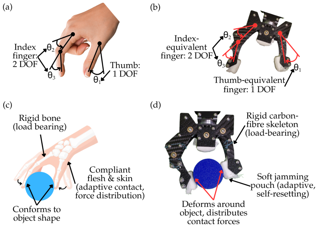
Kinematic inspiration: The human hand achieves dexterous grasping through a combination of multiple DOF. For precision grasping and enveloping, the thumb provides opposition with a primary flexion-extension DOF, while the index finger contributes two DOF (proximal and distal interphalangeal joints) to wrap around objects (
Figure 1a). Our gripper replicates this configuration exactly: a cable-driven, two-finger gripper with three DOF (
Figure 1b). This kinematic matching enables human-like enveloping grasps where the thumb opposes the index finger to secure objects.
Structural inspiration: The human hand’s rigid bones provide load-bearing strength and structural integrity, while the surrounding compliant flesh, muscles, and skin passively conform to object shapes during grasping (
Figure 1c). This soft tissue distributes contact forces, prevents local stress concentration, and allows stable gripping even on irregular surfaces. Our gripper emulates this bone-and-flesh architecture through a hybrid design: rigid carbon-fibre plates are employed to provide structural strength and load transmission. Soft, adaptive jamming pouches integrated at the fingertips and finger belly replace the compliant soft tissue: they passively conform to the grasped object, distribute contact forces, and self-reset after each grasp without external actuation (
Figure 1d).
2.2. Passive Jamming Principle and Jamming Pouch Design
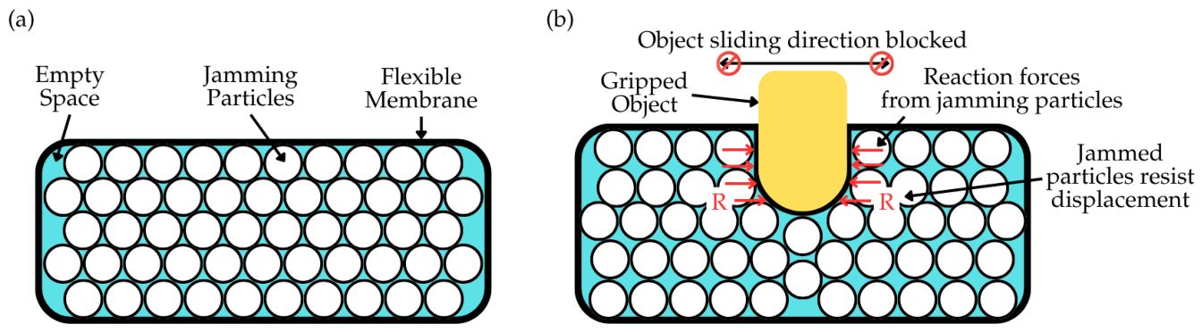
The key innovation is the integration of passive jamming pouches at the thumb tip, index fingertip, and finger belly. In conventional jamming, a flexible membrane filled with granular material is evacuated by a vacuum pump, causing the particles to compact and the pouch to become rigid. In contrast, the passive jamming principle (
Figure 2) activates the jamming effect solely by the contact force between the pouch and the object: as the object presses against the pouch, the granular particles are progressively compressed until they jam, without any external vacuum or pressure.
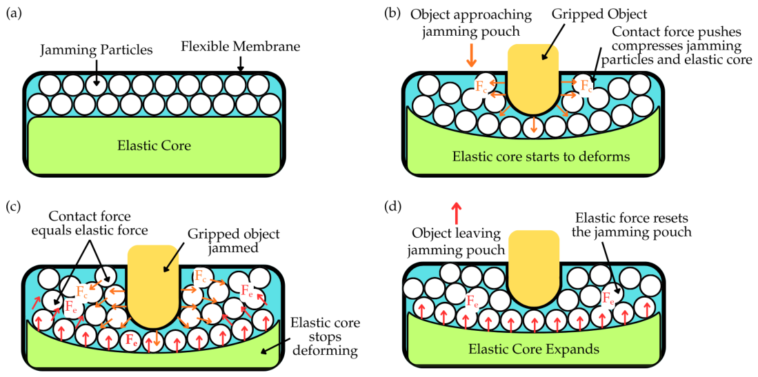
The proposed passive jamming pouches incorporate a self-reset mechanism achieved by a 3D-printed TPU elastic core (Zhuhai Sunlu Industrial Co., Ltd., Zhuhai, China) embedded inside the pouch, positioned behind the granular particles.
Figure 3 illustrates the four-state operational sequence.
- (a)
Default state: The elastic core is fully expanded, keeping the fabric membrane taut and the jamming particles loose and fluid. The pouch is compliant and ready to receive an object.
- (b)
Object approaching: As the gripper closes, the object contacts the fabric membrane and begins to deform the pouch. The increasing contact force drives the jamming particles to rearrange and gradually compact, forming local force chains that transmit the load to the elastic core. Meanwhile, the membrane starts to conform to the object’s geometry.
- (c)
Jammed state: When the contact force equals the elastic restoring force of the core, the particles become densely packed and lock together (jam). The membrane conforms exactly to the object’s shape, and the pouch becomes rigid, securely gripping the object.
- (d)
Object leaving: After the gripper opens, the elastic core expands back to its original shape. This expansion pushes the membrane outward and fluidizes the jamming particles, resetting the pouch to its compliant default state—ready for the next grasp.
This entirely passive mechanism eliminates the need for pneumatic pumps, valves, or additional electrical components, thereby reducing system complexity and energy consumption. Meanwhile, the jamming pouch fingertips can conform to the geometry of the grasped object, providing additional mechanical support and increasing the contact area. This conformal contact may help reduce local stress concentration and enhance frictional interaction between the fingertips and the object. These effects could contribute to a larger effective gripping force and improved grasping stability, particularly for irregularly shaped objects.
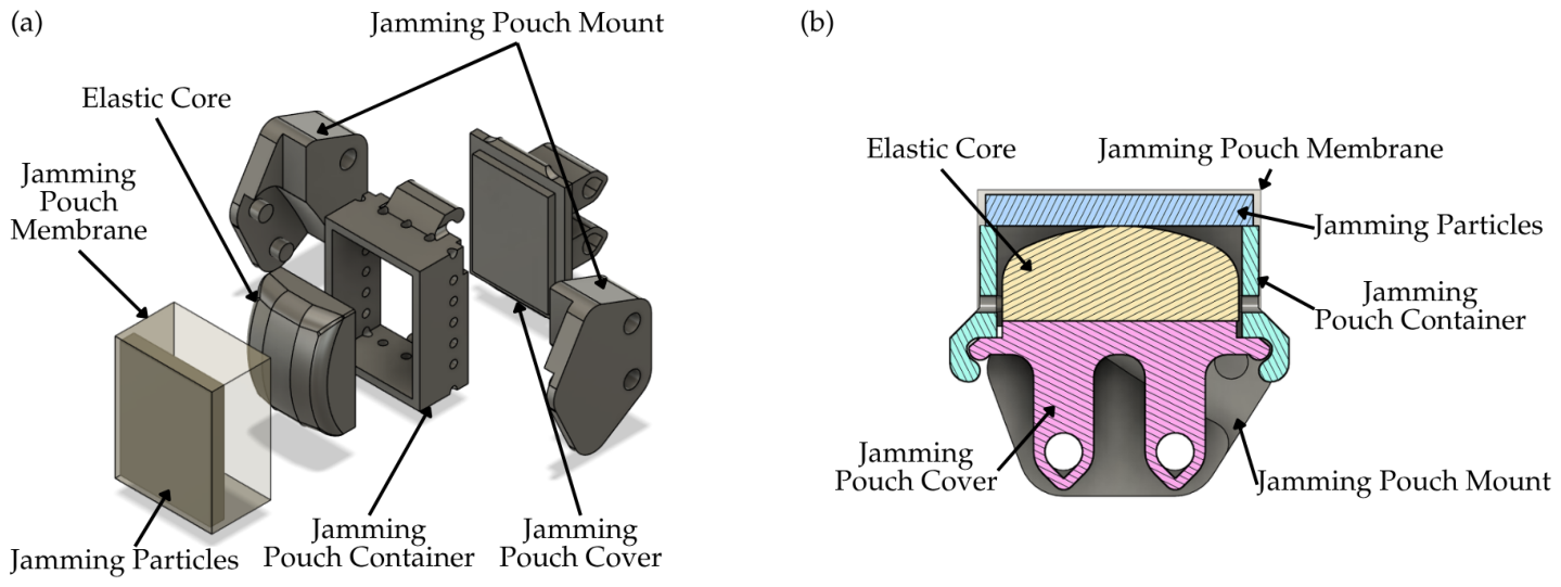
The jamming-enabled pouch is designed as illustrated in
Figure 4, comprising six main components: a rigid container, a cover, and a mount (all 3D-printed in PLA+, Zhuhai Sunlu Industrial Co., Ltd., Zhuhai, China); a flexible pouch membrane (polyester fabric); an elastic core (8.5 × 21.2 × 15.8 mm
3 and 8.5 × 21.2 × 5.8 mm
3 for thumb and index finger jamming pouch respectively and an estimated stiffness of 4.5–30.0 N/mm); and granular jamming particles. Filleted corners are incorporated into the elastic core to mitigate stress concentrations and prevent cracking observed in earlier rectangular designs.
2.3. Cable-Driven Gripper Configuration
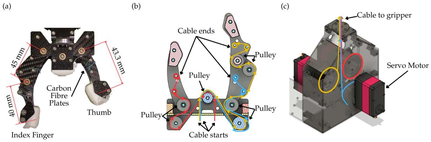
The gripper is a cable-driven, two-finger mechanism with three DOFs: a thumb-equivalent finger (with 43.3 mm link length) and an index-equivalent finger (with 45 mm and 40 mm proximal and distal link length respectively) (
Figure 5a). The fingers are fabricated from carbon fibre plates for high stiffness-to-weight ratio. Braided cables (0.8 mm diameter, 150 lb breaking strength) transmit actuation forces via a system of 10.5 mm diameter pulleys that redirect the cables from the servo motors to the specific joints of each finger (
Figure 5b). This pulley-based routing allows the cables to follow a compact, low-friction path, enabling precise control of finger flexion.
Three RDS5160 servo motors (Shenzhen Desheng Servo Technology Co., Ltd., Shenzhen, China) provide actuation for the gripper, each with a maximum rated current of 3 A. A key design feature is the use of remotely located actuation: the servo motors are mounted on a stationary base, separate from the moving fingers, and transmit motion through a cable–pulley network (
Figure 5c). This configuration significantly reduces the mass and inertia of the moving components, which is particularly important for applications such as logistics and food handling, where a lightweight end-effector minimises dynamic loads on the robotic arm and reduces the risk of damaging delicate objects.
The control system is implemented using an Arduino UNO microcontroller (Arduino S.r.l., Monza, Italy), which reads three two-axis analogue joystick modules and generates PWM signals for the servo motors, as well as step and direction signals for the linear actuator. To ensure stable operation, each servo motor is powered by an independent, isolated DC power supply (WANPTEK NPS3010W or NPS306W, Shenzhen Wanptek Electronic Technology Co., Ltd., Shenzhen, China). This power supply isolation ensures that each actuator receives stable and uninterrupted power, preventing voltage drops and current sharing issues associated with a single supply, while also reducing electrical noise.
Passive finger reset is achieved by torsion springs (65Mn spring steel, Shenzhen Hulida Hardware Co., Ltd., Shenzhen, China) placed at each joint, with a wire diameter of 0.6 mm, outer diameter of 6.5 mm, 3 active coils, a 120° spring angle, a stiffness coefficient of 142.37 N·mm/rad, and a preload angle of around 90°. When the servos relax, the springs return the fingers to the open position. The combination of cable-driven transmission, remote actuation, and spring-assisted reset yields a compact, low-mass gripper capable of high-speed operation and safe interaction with fragile objects.
2.4. Tested Jamming Pouch Configurations and Fabrication
All tests were conducted with the final jamming pouch design. The following configurations were evaluated (
Table 1):
Rigid fingertip (baseline): No jamming pouch; 3D-printed PLA+ fingertip.
Fabric membrane + rice particles at three fill volumes (3 mm, 6 mm, 9 mm).
Fabric membrane + green beans. Green beans had average dimensions of approximately 2–3 mm diameter and 4–5 mm length.
Fabric membrane + aluminium oxide balls (1–2 mm diameter).
TPU core only (no particles): The pouch contained only the TPU elastic core, with no granular material. This configuration isolated the contribution of the elastic core from that of the jamming particles.
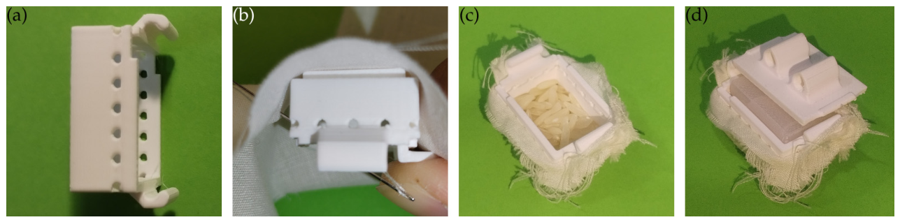
All custom components were fabricated using fused deposition modelling (FDM) on a Bambu Lab P1S printer (Shenzhen Tuozhu Technology Co., Ltd. [Bambu Lab], Shenzhen, China). Structural parts (containers, mounts, test objects) used Sunlu PLA+ filament (nozzle 220 °C, layer height 0.2 mm). Elastic cores used Sunlu TPU 95A. The fabric membrane was hand-sewn onto the container using standard sewing thread. The complete fabrication sequence is illustrated in
Figure 6. With the pusher and optimised sewing holes, each pouch required approximately 7–8 min to complete (reduced from 15 to 20 min in earlier iterations).
2.5. Experimental Setup and Objects
A dedicated test rig (
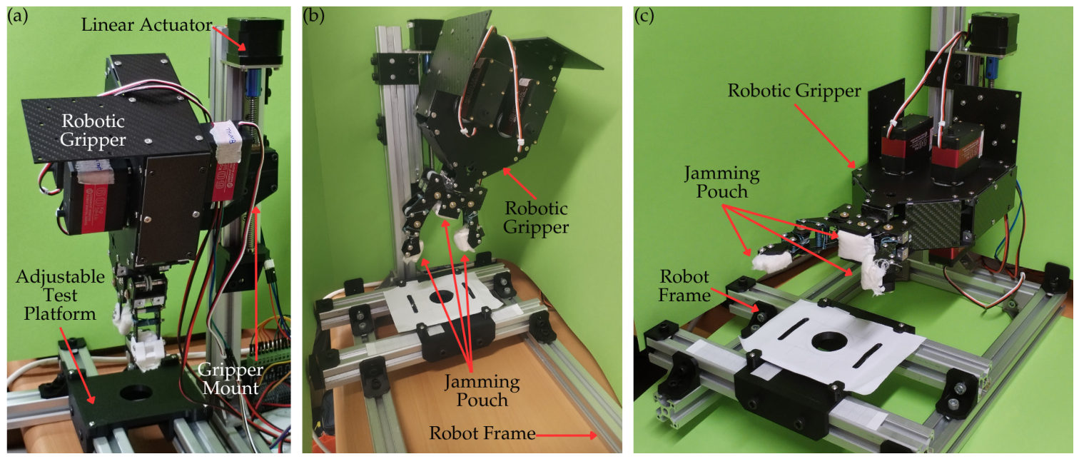
Figure 7a) was constructed from 3030 aluminium profile (30 mm × 30 mm cross-section) with gusset joints. The experimental setup includes an adjustable test platform, a linear actuation system, and a gripper mounting structure. The adjustable platform consists of a two-piece 3D-printed assembly, providing ±100 mm lateral adjustment and ±20 mm longitudinal adjustment. The linear actuator is mounted vertically and driven by a stepper motor, with a stroke of 100 mm, and is controlled by a TB6600 micro-step driver (Shenzhen YouSheng GuangCai Electronics Co., Ltd., Shenzhen, China) operating in full-step mode at 2.0 A. The gripper is attached to a custom 3D-printed mounting bracket with slotted holes for angular alignment, allowing testing in both vertical and horizontal orientations.
To evaluate the versatility of the proposed gripper, two gripping orientations were tested, as shown in
Figure 7b,c. In the vertical orientation (
Figure 7b), the gripper approaches the object from above, mimicking a typical pick-and-place operation where objects are grasped from a horizontal surface. In the horizontal orientation (
Figure 7c), the gripper approaches from the side, simulating scenarios in which objects are presented on a vertical plane or where side grasping is required due to spatial constraints.
To ensure consistent and safe operation across all test conditions, the driving current of each servo motor in the hybrid gripper was limited to 1 A, which is well below its maximum rated value. This current limitation was used to provide a consistent upper bound on the actuation effort during all experiments, regardless of object configuration or grasping orientation, thereby reducing variability that could otherwise affect the comparison of payload capacities among different jamming pouch designs. It should be noted that the current prototype did not employ high-precision closed-loop force control or real-time force feedback for regulating the clamping force. Instead, all grippers were tested under the same open-loop control condition and current limit, so that the comparison primarily reflected the intrinsic mechanical contribution of different fingertip configurations rather than the influence of advanced control strategies.
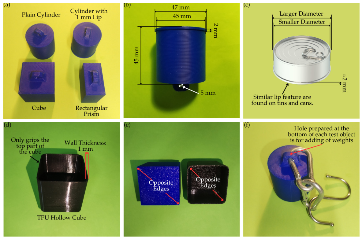
Four rigid test objects, as shown in
Figure 8a, were 3D-printed using PLA+ to represent common industrial geometries:
Plain cylinder: Representative of bottles, cans, and cylindrical containers (Ø45 mm × 45 mm).
Cube: Representative of boxes and prismatic packages (45 mm × 45 mm × 45 mm).
Rectangular prism: Representative of flat-packaged items (45 mm × 25 mm × 45 mm).
Cylinder with a 1 mm lip: The lip mimics the rim of a tin or can (
Figure 8b,c), providing a mechanical feature that can be engaged by the gripper. This object evaluates the gripper’s ability to exploit such features for enhanced payload capacity (Ø47 mm at lip, Ø45 mm body, lip’s width = larger radius—smaller radius).
An additional test object shown in
Figure 8d, a hollow cube made of TPU (thermoplastic polyurethane) with a wall thickness of 1 mm, was 3D-printed to represent a deformable, lightweight object such as a cardboard box or a flexible package. This deformable cube and the rigid cube will be used in edge gripping test where their opposite edges will be gripped (
Figure 8e).
Each object was designed with an integrated 5 mm diameter through hole at the base to allow the attachment of additional weights for systematic payload testing, as illustrated in
Figure 8f.
2.6. Testing Protocol
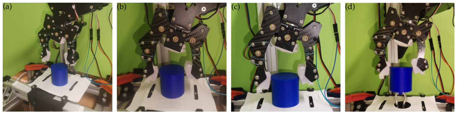
The test procedure, as illustrated in
Figure 9, was standardised and consistently applied across all configurations and test objects.
- (a)
Positioning: The test object was placed on the adjustable platform at the predetermined optimal position (centred, with gripper fingers parallel to the object’s grasping surfaces).
- (b)
Approach: The linear actuator lowered the gripper until the fingers reached approximately the object’s centroid height.
- (c)
Gripping: The servos were manually actuated using a joystick until the current from the DC power supply reached the preset limit of 1 A. The motor velocity was set to 352.9°/s, corresponding to approximately 58.8 rpm. The same speed setting was used for all tested grasping configurations. For the TPU hollow cube (deformable object), the gripping criterion differed from the standard current-limiting approach. Because the thin wall would be crushed if the full 1 A gripping force were applied, the servos were actuated until the finger displacement reached 2 mm measured from the initial contact point (i.e., the deformable wall was compressed by 2 mm).
- (d)
Lift: The linear actuator raised the gripper by 15–20 mm and held stationary for approximately 5 s.
- (e)
Lower and release: The actuator lowered the gripper, and the fingers were opened.
- (f)
Success criterion: A trial was successful if the object remained securely gripped throughout steps 3–5 (from gripping completion through the 5 s hold). Ten consecutive successful lifts were required to declare a given payload as achievable.
Payload measurement: Starting from a baseline mass of 100 g (object + harness), additional weights were added in increments of 100 g. The maximum payload was defined as the highest mass for which ten consecutive lifts were successful. If a failure occurred, the weight was reduced to the previous successful level and confirmed with another ten lifts. For each weight and object, the ten consecutive lifts were performed once (i.e., no repeated series at the same weight).
Opposite edge grip test (vertical orientation only): To evaluate the gripper’s ability to grasp sharp, narrow features, opposite edge grip tests were performed on two cube-shaped objects: the rigid PLA cube (45 × 45 × 45 mm) and the TPU hollow cube. The gripper fingers were positioned to contact the two opposite vertical edges of the cube (not the flat faces). This configuration simulates scenarios where only the edges of an irregular object are accessible (e.g., grasping a circuit board, a book, or a thin package). The same lifting procedure and success criterion (ten consecutive successful lifts) as described above were applied.
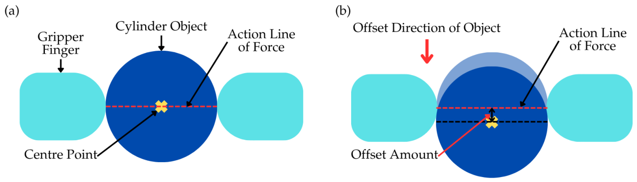
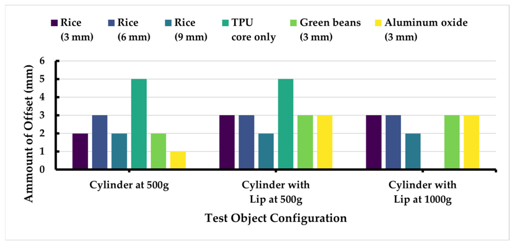
Lateral offset tolerance test: The gripper’s ability to tolerate horizontal misalignment was evaluated on the plain cylinder (at 500 g payload) and on the cylinder with lip (at 500 g and 1000 g payloads). Starting from the centred optimal position, the test platform was shifted laterally in 1 mm increments. At each offset, the lifting procedure was. For each offset, ten consecutive lifts were performed, and the trial was considered successful only if all ten lifts succeeded. The maximum offset that still allowed a successful lift (after ten consecutive successes) was recorded.
Figure 10 provides a schematic overview of the offset test procedure.
Number of cycles: Each successful configuration was tested over approximately 50 lifting cycles for payload determination. The total cumulative cycles across all tests exceeded 1000, during which the TPU elastic cores were visually inspected for degradation.
All reported payloads are the maximum values achieved with 100% repeatability over ten consecutive trials. No formal statistical hypothesis tests were applied, as the performance differences were large and deterministic. Results are presented in the following section.
3. Results
A total of seven fingertip configurations were evaluated: rigid tip (baseline), jamming pouches filled with rice at three fill volumes (3 mm, 6 mm, 9 mm), jamming pouches filled with green beans, jamming pouches filled with aluminium oxide balls, and pouches containing only the TPU elastic core (no particles). Tests were conducted in both vertical and horizontal gripper orientations. The cylinder-with-lip object was tested only in the vertical orientation, as side-grasping of a lipped object is not typical in practice.
All reported payloads represent the maximum mass (in grams) lifted successfully in ten consecutive trials (100% repeatability). Lateral offset tolerance (vertical orientation only) was measured for the plain cylinder at the three highest payload levels for each configuration.
In addition to payload tests, the maximum static holding force of the jamming gripper was measured directly. The gripper was actuated to grip a digital weighing scale (as a surrogate flat surface), and the scale reading was recorded. The average maximum holding force was approximately 850 g (8.34 N). This value was used to estimate the coefficient of friction of the fabric membrane (see
Section 4.2).
3.1. Payload Performance for Standard Objects
To evaluate the gripper’s performance on objects without mechanical undercuts, payload tests were conducted on the plain cylinder, cube, and rectangular prism in both vertical and horizontal orientations.
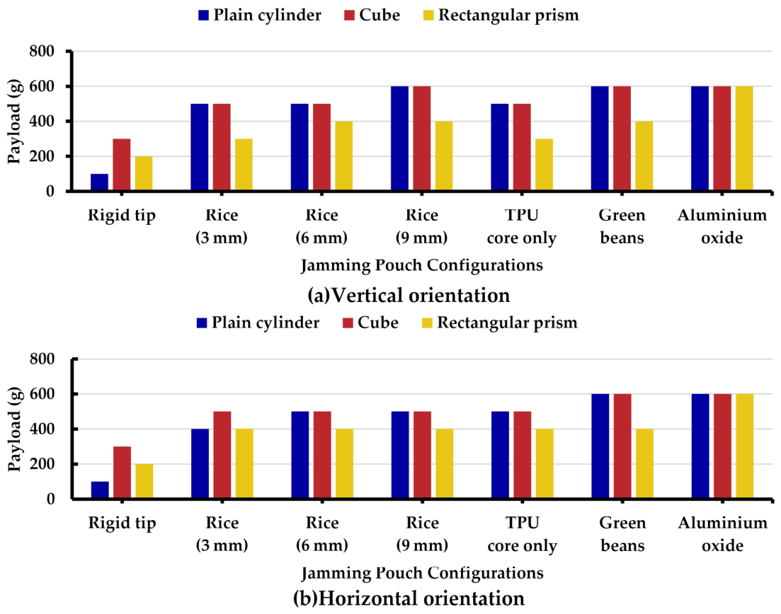
Figure 11 presents the maximum payloads achieved for each configuration, where
Figure 11a shows the vertical orientation and
Figure 11b shows the horizontal orientation.
Improvement ratios (relative to rigid tip baseline):
Plain cylinder: The best jamming configurations (600 g) achieved a 6× improvement over the rigid tip (100 g) in both orientations.
Cube: The best configurations (600 g) achieved a 2× improvement over the rigid tip (300 g) in both orientations.
Rectangular prism: Aluminium oxide balls (600 g) achieved a 3× improvement over the rigid tip (200 g) in both orientations. Other jamming pouches (400 g) achieved a 2× improvement in horizontal orientation; in vertical orientation, rice (3 mm) and TPU-only reached 300 g (1.5×).
Effect of fill volume (rice particles): For the plain cylinder in vertical orientation, increasing the rice fill volume from 3 mm to 9 mm increased the payload from 500 g to 600 g (1.2×). The same trend was observed for the cube (500 g to 600 g, 1.2×) and for the rectangular prism (300 g to 400 g, 1.33×). In horizontal orientation, the 6 mm and 9 mm fills both achieved 500 g on the plain cylinder and cube, outperforming the 3 mm fill (400 g on cylinder, 500 g on cube). For the rectangular prism horizontally, all rice fills achieved 400 g, with no improvement beyond 3 mm.
Effect of particle type: Among the 3 mm fill volume configurations, green beans and aluminium oxide balls consistently achieved the highest payloads across both orientations. For the plain cylinder in vertical orientation, both reached 600 g, compared to 500 g for rice and TPU-only. In horizontal orientation, green beans and aluminium oxide again reached 600 g on the plain cylinder and cube, while rice (3 mm) achieved only 400 g on the cylinder and 500 g on the cube. The TPU-only configuration performed similarly to rice (3 mm) on most standard objects, achieving 500 g on the plain cylinder and cube, and 300 g on the rectangular prism. Aluminium oxide balls excelled on the rectangular prism, reaching 600 g in both orientations—a 2× improvement over rice and TPU-only.
Orientation effects: For most configurations, vertical orientation yielded slightly higher payloads than horizontal orientation, particularly on the plain cylinder (e.g., rice 3 mm: 500 g vertical vs. 400 g horizontal). The rectangular prism with aluminium oxide achieved 600 g in both orientations, showing that hard, spherical particles maintain performance irrespective of approach direction. Overall, the jamming pouches demonstrated robust performance in both orientations.
3.2. Payload Performance for Challenging Geometries (Edge Gripping and Undercuts)
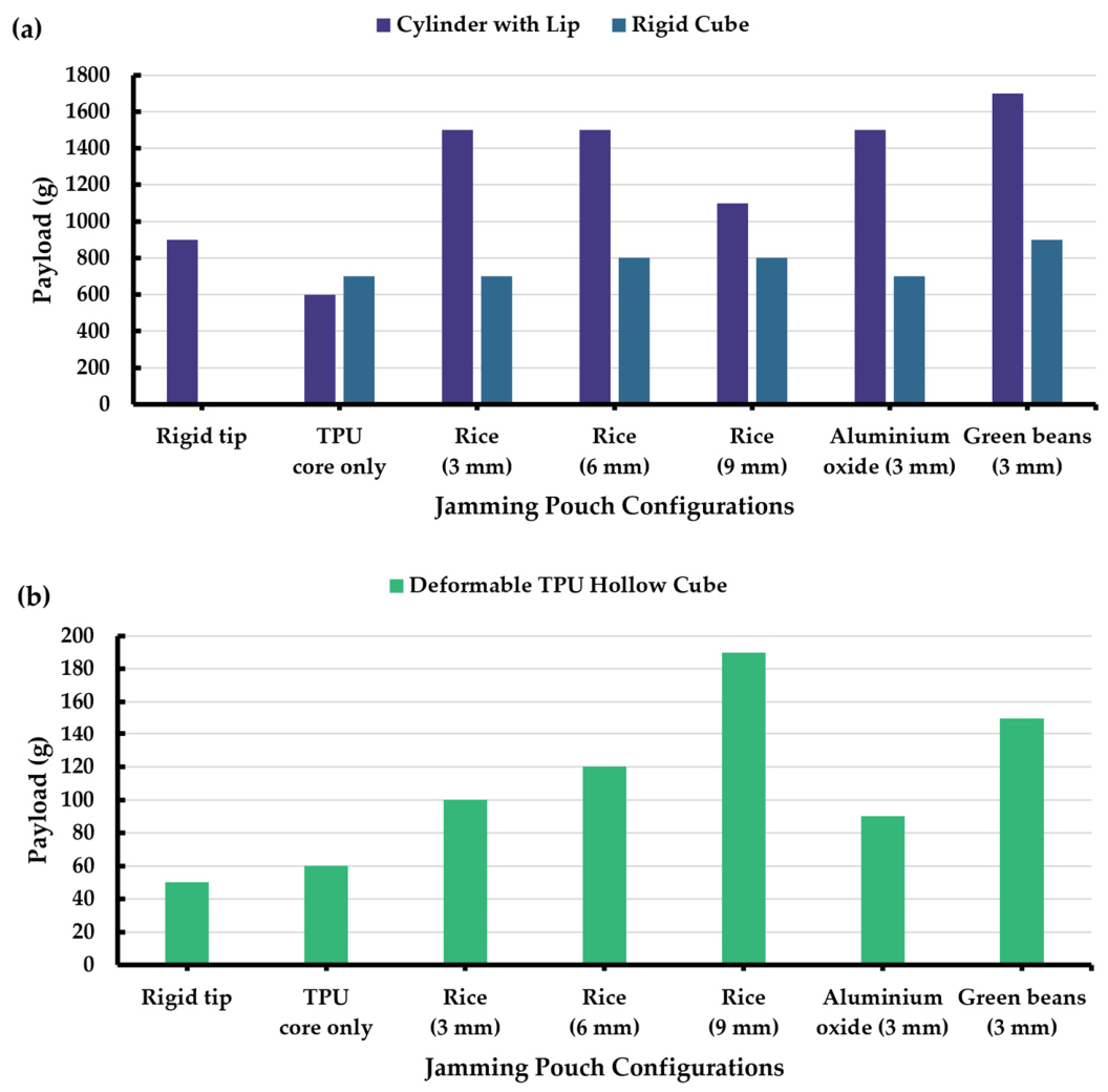
Figure 12 presents the maximum payloads achieved for three challenging geometries: cylinder with lip (undercut), rigid cube with opposite edge grip, and TPU hollow cube with opposite edge grip. For the TPU hollow cube, the gripping force was limited by a finger displacement of 2 mm (rather than the 1 A current limit) to prevent crushing the thin wall. All tests were performed in the vertical orientation.
Observations and improvement ratios (relative to rigid tip baseline):
Cylinder with lip: The rigid tip achieved 900 g. Green beans (3 mm) reached 1700 g, corresponding to a 1.89× improvement. Rice (3 mm and 6 mm) and aluminium oxide (3 mm) each reached 1500 g (1.67×). Rice (9 mm) reached 1100 g (1.22×). The TPU-only configuration achieved 600 g (0.67×).
Rigid cube with opposite edge grip: The rigid tip could not repeatedly grip the sharp edge, resulting in a payload of 0 g. All jamming pouch configurations succeeded. Green beans (3 mm) achieved the highest payload (900 g). Rice (6 mm and 9 mm) achieved 800 g. Rice (3 mm), TPU-only, and aluminium oxide (3 mm) achieved 700 g.
TPU hollow cube with opposite edge grip: The rigid tip achieved 50 g. Rice (9 mm) reached 190 g (3.8× improvement). Green beans (3 mm) reached 150 g (3.0×). Rice (6 mm) reached 120 g (2.4×). Rice (3 mm) reached 100 g (2.0×). Aluminium oxide (3 mm) reached 90 g (1.8×). The TPU-only configuration achieved 60 g (1.2×).
Effect of fill volume (rice particles): For the cylinder with lip, increasing the rice fill volume from 3 mm to 6 mm maintained the same payload (1500 g), while the 9 mm fill reduced the payload to 1100 g (0.73× relative to 1500 g). For the rigid cube opposite edge grip, the 3 mm fill achieved 700 g, while both 6 mm and 9 mm fills reached 800 g (1.14× improvement over 3 mm). For the TPU hollow cube opposite edge grip, increasing the fill volume consistently increased the payload: 3 mm (100 g), 6 mm (120 g, 1.2×), and 9 mm (190 g, 1.9×).
Effect of particle type: Among the 3 mm fill configurations, green beans achieved the highest payload on the cylinder with lip (1700 g), the rigid cube opposite edge grip (900 g), and the TPU hollow cube opposite edge grip (150 g). Aluminium oxide performed well on the cylinder with lip (1500 g) and on the rigid cube (700 g) but was outperformed by rice (3 mm) on the TPU hollow cube (90 g vs. 100 g). The TPU-only configuration gave the lowest payloads among jamming pouches in all three cases: 600 g (cylinder with lip), 700 g (rigid cube), and 60 g (TPU hollow cube).
3.3. Lateral Offset Tolerance (Vertical Orientation, Plain Cylinder Only)
Figure 13 presents the maximum lateral offset tolerated by each configuration for the plain cylinder (500 g) and the cylinder with lip (500 g and 1000 g). The rigid tip was also tested at these payloads.
Key observations:
The rigid tip tolerated zero offset in all three tests.
The TPU-only configuration tolerated the highest offset on the plain cylinder (5 mm) and on the lipped cylinder at 500 g (5 mm), but its tolerance dropped to 0 mm at 1000 g on the lipped cylinder.
Rice (6 mm) tolerated 3 mm in all three tests.
Rice (3 mm), rice (9 mm), and green beans (3 mm) tolerated 2 mm on the plain cylinder, and 2–3 mm on the lipped cylinder.
Aluminium oxide (3 mm) tolerated 1 mm on the plain cylinder but 3 mm on the lipped cylinder at both payloads.
4. Discussion
This study set out to design, fabricate, and evaluate a hybrid rigid–soft gripper that integrates passive jamming pouches onto a cable-driven rigid gripper. The central hypothesis was that such a hybrid approach could bridge the fundamental trade-off between high payload capacity (rigid grippers) and high adaptability (soft grippers), while eliminating the need for pneumatic actuation through a passive self-resetting mechanism. The results presented in
Section 3 provide strong support for this hypothesis, with several notable findings discussed below.
4.1. Shape-Dependent Performance and Mechanism Insights
Cylindrical objects: The plain cylinder showed the highest improvement ratio (6×) among all objects. Experimental observations suggest that this improvement is mainly related to the contact mode. With the rigid fingertip, the plain cylinder was supported only by a small contact region, and even slight misalignment could cause the object to slip or be ejected. In contrast, the jamming pouch conformed to the cylindrical surface and generated a larger distributed contact area. The TPU-only configuration also achieved 500 g on the plain cylinder—equal to rice (3 mm)—indicating that the elastic core alone provides significant conformability. However, on the lipped cylinder, the rigid tip already hooked under the lip (900 g). The particle-filled pouches improved this further by jamming into a custom-moulded shape that interlocks with the lip, reaching up to 1700 g (green beans). The TPU-only pouch, lacking granular jamming, could not lock into the undercut and achieved only 600 g. This contrast confirms that while the elastic core offers basic adaptability, granular jamming is essential for exploiting geometric features like lips or undercuts.
Cuboid objects (cube and rectangular prism): Improvement ratios were more modest (2× to 3×). The TPU-only configuration performed similarly to rice (3 mm) on the cube (500 g) and on the rectangular prism (300 g). The best performer on the rectangular prism was aluminium oxide balls (600 g, 3× improvement), demonstrating that hard, spherical particles can pack densely and generate high normal forces on flat surfaces.
Role of particle type: The performance differences between particle types reveal an interaction between particle morphology and object geometry. Soft, irregular particles (green beans) performed best on the lipped cylinder (1700 g) and on the rigid cube edge (900 g), where they can flow around and lock into undercuts or wrap around sharp edges. Hard, spherical particles (aluminium oxide) performed best on the flat rectangular prism (600 g) and also gave competitive results on the cylinder with lip (1500 g) and rigid cube edge (700 g). Rice (medium hardness, elongated) gave intermediate performance, but notably, rice 9 mm excelled on the TPU hollow cube edge (190 g)—the highest among all configurations—suggesting that a larger volume of moderately hard particles can effectively support thin walls without crushing. These findings align with Götz et al. [
39], who reported that soft particles lead to significantly larger gripping forces in comparison to rigid particles.
Trade-off between fill volume and reset reliability: An important trade-off was observed regarding particle fill height. Increasing the rice fill height from 3 mm to 9 mm improved the payload on the plain cylinder, rigid cube, and TPU hollow cube edge from 500 g to 600 g, 500 g to 600 g, and 100 g to 190 g, respectively. However, this improvement was accompanied by a reduced self-reset capability. The 9 mm pouch reset more slowly and incompletely compared to the 3 mm pouch, which always returned to its default state immediately. This is attributed to the increased mass and internal friction of the larger particle bed, which the TPU elastic core must overcome. Designers must therefore balance payload requirements against reset reliability: lower fill volumes ensure robust self-reset, while higher fill volumes may be chosen only when maximum payload is critical and reset speed is less important.
4.2. Lateral Offset Tolerance: A Key Advantage for Real-World Applications
The lateral offset tolerance test revealed one of the most significant practical advantages of the jamming pouch. The rigid fingertip tolerated zero offset; any misalignment caused immediate failure. In contrast, all jamming pouch configurations tolerated at least 1 mm of offset, with the TPU-only configuration tolerating up to 5 mm at 500 g.
Mechanism: The conformable pouch effectively “absorbs” positioning errors by deforming around the object even when the gripper is not perfectly centred. This is a form of passive error compensation that does not require sensing or active control.
Comparison among configurations: Rice (6 mm) tolerated 3 mm offset on the plain cylinder, better than rice (3 mm) and rice (9 mm) (both 2 mm offset only). The TPU-only configuration’s exceptional offset tolerance on the plain cylinder (5 mm offset) is likely because the TPU surface is smoother and deforms less locally. When pressed against a misaligned cylinder, the relatively flat and uniform TPU surface maintains a larger effective contact area. However, on the lipped cylinder at 1000 g, the TPU-only tolerance dropped to 0 mm, indicating that without granular jamming, the pouch cannot sustain the required normal force to keep the lip engaged under high load. In contrast, all particle-filled pouches tolerated 2–3 mm on the lipped cylinder even at 1000 g, demonstrating the robustness of granular jamming. Aluminium oxide balls tolerated only 1 mm on the plain cylinder, likely because of their high packing density and rigidity, but on the lipped cylinder they achieved 3 mm, suggesting that the lip helps centre the pouch. Green beans and rice (3 mm, 6 mm) gave 2–3 mm across all tests.
Practical implications: In industrial pick-and-place, vision systems and part feeders have inherent positional tolerances (typically ±1–2 mm). A gripper that can tolerate 2–3 mm of misalignment without performance loss simplifies system integration, reduces calibration time, and lowers the required precision (and cost) of upstream equipment. The 5 mm tolerance of the TPU-only configuration is particularly impressive, though it would only be suitable for objects without undercuts.
4.3. Passive Self-Reset Reliability
Over approximately 1000 gripping cycles, no performance degradation was observed in any of the jamming pouch configurations. The TPU elastic cores showed no visible cracking or permanent deformation after the initial design refinement (filleted corners). This validates the passive self-reset mechanism as a robust, maintenance-free alternative to pneumatic or motorised reset systems.
Compared to active jamming grippers that require vacuum pumps, solenoid valves, and pressure sensors [
32,
34], the present design reduces part count, energy consumption, and control complexity. The only “actuation” is the mechanical work done by the servo motors to close the fingers; the jamming and reset happen passively. This makes the gripper particularly suitable for mobile robotics, field robotics, and other applications where compressed air is unavailable.
4.4. Addressing the Research Gap
The proposed design addresses the research gap identified in the Introduction and meets all four criteria:
Adaptability: Conforms to cylinders, cubes, rectangular prisms, and lipped objects without reconfiguration.
Passive jamming and self-reset: Activated by contact force; no vacuum or pressure required, while the TPU elastic core provides a reliable reset for >1000 cycles.
High payload: Up to 1700 g (1.89× rigid tip) on lipped objects; 600 g (6×) on plain cylinders.
Compliant behaviour for effective grasping: The 3-DOF cable-driven mechanism allows the servo motors to be placed remotely, reducing the moving mass of the gripper—a critical advantage for lightweight robotic arms and delicate handling tasks.
The TPU-only configuration, while not strictly a “jamming” gripper, offers an alternative for applications prioritising misalignment tolerance over peak payload on complex geometries.
4.5. Implications for Embodied Design
The passive adaptability of the jamming pouch aligns with the embodied design philosophy introduced in the Introduction. Rather than relying on sensors, algorithms, or closed-loop control, the physical structure of the pouch (membrane, particles, elastic core) embeds the adaptive behaviour. The gripper “intelligently” conforms to objects and self-resets without any computation beyond the servo position commands. This reduces control complexity, energy consumption, and cost—all valuable attributes for mobile and field robotics. To further clarify the distinction between the proposed design and existing works, a detailed comparison is provided in the
Supplementary Materials.
The TPU-only configuration represents an even simpler embodiment. However, without granular jamming, the pouch cannot lock into a rigid, custom-shaped mould. As a result, it performs poorly on objects with undercuts, achieving only 600 g instead of 1700 g. This illustrates a fundamental trade-off in embodied design: adding morphological complexity (i.e., the granular particles) enables new capabilities (jamming into undercuts) but increases mechanical complexity. Conversely, relying purely on material compliance (TPU only) keeps the design simple but limits functionality. The designer must choose the appropriate level of morphological complexity for the target application.
5. Conclusions
Inspired by the kinematics and structure of the human hand, this paper presents a hybrid rigid–soft gripper that integrates a 3-DOF cable-driven rigid skeleton with passive, self-resetting granular jamming pouches. The proposed design achieves high payload capacity, adaptability to diverse object geometries, and inherent tolerance to positioning errors, without requiring additional actuation for jamming.
Experimental results demonstrated that the jamming pouch configurations substantially outperformed rigid fingertips. The plain cylinder showed a 6× payload improvement (100 g to 600 g), and the lipped cylinder reached 1700 g (1.9× over the rigid tip). For the lipped cylinder, the particle-filled jamming pouches outperformed the TPU-only configuration by a factor of up to 2.8 (1700 g vs. 600 g), demonstrating the necessity of granular jamming for exploiting geometric undercuts. When grasping sharp edges (opposite edge grip), the rigid tip failed completely on a rigid cube (0 g), whereas all jamming pouches succeeded, with green beans reaching 900 g. On a thin-walled, deformable TPU hollow cube (gripped with a 2 mm finger displacement limit to avoid crushing), the rigid tip achieved only 50 g, while rice 9 mm attained 190 g (3.8× improvement). The gripper tolerated up to 5 mm lateral misalignment (TPU-only) and at least 2 mm for particle-filled pouches, whereas rigid tips tolerated zero offset. Particle type and fill volume significantly affect performance: soft, irregular particles (green beans) excel on undercuts, while hard, spherical particles (aluminium oxide) perform best on flat surfaces. Increasing fill volume improves payload but degrades self-reset reliability. The passive self-reset mechanism, based on a 3D-printed TPU elastic core, remained reliable over 1000 cycles, validating its robustness.
The main limitations of this study are the unoptimized fabric membrane, the limited range of particle types, potential fabrication variability in the manually sewn jamming pouches, and the absence of tests on fragile workpieces. In particular, manual pouch fabrication may introduce variations in pouch geometry, seam consistency, and particle distribution, which could affect the repeatability of the fingertip response. Future work will investigate higher-friction membrane materials, systematic particle optimisation, more reproducible pouch fabrication methods, closed-loop force control, long-term durability, and grasping performance on a broader range of fragile, irregular, and application-specific objects. Overall, the proposed gripper provides a practical and low-complexity solution for automated handling in logistics, food processing, and mobile robotics, where energy efficiency and positional error tolerance are important.