1. Introduction
Industrial robots are capable of performing a wide range of tasks, including welding, polishing, assembly, painting, and material handling [
1]. With the advancement of industrialization, significant progress has been achieved in robot design and manufacturing technologies. However, the operating equipment of robots is frequently influenced by environmental factors, which may lead to wear, corrosion, and component degradation. These challenges can result in frequent anomalies, gradually reducing the efficiency and service life of robots, and in some cases even causing catastrophic failures. Therefore, the development of robust fault diagnosis methods is essential for maintaining operational efficiency and ensuring reliable system performance.
When anomalies occur in industrial robots, maintenance costs typically account for 60% to 70% of the total lifecycle production costs. Implementing optimal maintenance strategies is crucial for reducing operational expenses and minimizing equipment downtime [
2]. Consequently, the industry is actively exploring new fault diagnosis approaches, primarily leveraging widely available sensor data, as well as machine learning and deep learning techniques.
In robotic joint systems, bearings play a dual role in supporting loads and ensuring motion precision. Their operating condition directly impacts the positioning accuracy and dynamic response capability of the end effector. Compared to traditional rotating machinery, industrial robot bearings typically operate under complex conditions such as frequent start-stop cycles, variable-speed operation, and multi-axis coupled loads. This makes their degradation process more concealed and difficult to model. Furthermore, in practical production environments, for safety and cost reasons, equipment is often maintained before a severe fault occurs, resulting in a scarcity of real fault data and making it difficult to cover various failure modes [
2,
3]. The types of faults in robot joint bearings are shown in
Table 1.
From a maintenance perspective, manufacturing enterprises are gradually shifting from “scheduled maintenance” to “predictive maintenance,” and reliable fault diagnosis technology is a key foundation for this transition. Studies have shown that maintenance strategies based on condition monitoring can significantly reduce the risk of unplanned downtime and improve equipment utilization. Therefore, conducting fault diagnosis research for critical components of industrial robots under complex working conditions and data-limited scenarios holds significant engineering application value.
In the field of condition monitoring, a variety of signal analysis techniques have been proposed and applied, including approaches grounded in mathematical and algebraic methods [
4,
5,
6]. In intelligent equipment condition monitoring, machine learning algorithms are often integrated with fault mechanisms and signal analysis techniques. Commonly used methods include shallow learning algorithms such as Artificial Neural Networks, Extreme Learning Machines, and Support Vector Machines [
7,
8,
9,
10], as well as deep learning approaches such as Recurrent Neural Networks and Convolutional Neural Networks [
11,
12,
13]. Advances in sensor technology and signal analysis have further enhanced AI-driven condition monitoring, enabling more accurate fault diagnosis for industrial robots and ensuring the reliable and safe operation of critical components. Motors, bearings, and pumps play indispensable roles in various industrial systems and applications. As key assets in modern industry, they are required to operate with high reliability and safety. Based on a review of technical manuals and related documentation, faults in industrial robots are primarily concentrated in the joints, which comprise motors and bearings [
14,
15]. Therefore, it is crucial to monitor data from these joint components and conduct fault diagnosis in these critical areas.
Traditional maintenance approaches typically involve time-based strategies, including scheduled inspections and preventive maintenance. However, such periodic maintenance often leads to unnecessary inspections and corrective actions, such as replacing components that are still functional. Moreover, this type of maintenance may result in increased downtime [
16]. In contrast, condition-based maintenance detects faults through frequent and continuous monitoring of operational parameters. This approach generally relies on machine learning techniques and physics-based modeling [
17].
Fault diagnosis techniques for robots have long been a focal point for engineers and researchers. Xiao et al. [
18] proposed a multidimensional mini-batch approach that integrates Ensemble Empirical Mode Decomposition with the Martian system for fault diagnosis of industrial robot bearings. Researchers such as Si et al. [
19] proposed a fault diagnosis method for hexapod robots based on digital twin technology and an improved long short-term memory neural network integrated with graph convolutional networks. This approach demonstrates how the combination of digital twin modeling and advanced deep learning architectures can effectively enhance the accuracy and reliability of fault diagnosis in complex robotic systems. Qi et al. [
20] designed a multi-bearing fault diagnosis method for industrial robots based on truncated higher-order singular value decomposition. This method highlights the effectiveness of tensor decomposition techniques in capturing complex fault features, thereby improving diagnostic performance in multi-component robotic systems. All the aforementioned fault diagnosis methods are model-based. To achieve accurate diagnostic results, it is necessary to establish precise dynamic models of the robot. However, obtaining an accurate robot dynamic model is highly challenging, which limits the adaptability of model-based fault diagnosis approaches.
In recent years, advancements in sensor technology have made data-driven fault diagnosis methods highly effective. Data-driven models capture correlations between sensor data, allowing for the identification of abnormal data. The application of data-driven fault diagnosis methods has been a significant focus, particularly regarding data acquisition and availability. Ge et al. [
21] proposed a hub motor bearing fault diagnosis method based on SMOTE-IGWO-RF, effectively improving diagnostic accuracy by addressing data imbalance and optimizing model performance. He et al. [
22] proposed a multi-objective anomaly detection method that combines ensemble empirical mode decomposition and discrete wavelet decomposition for signal denoising, extracts time-domain features, and employs an improved whale optimization algorithm to optimize the parameters and features of support vector data description. Liu and colleagues [
23] addressed the issue of vibration signal extraction for rolling bearing fault diagnosis by introducing a new method based on Variational Mode Decomposition and the Vision Transformer model, providing an adaptive solution for this task. Niu et al. [
24] employed Gaussian random projection–support vector machines for fault diagnosis, achieving effective dimensionality reduction of multi-source information and designing a corresponding classification scheme. Ji et al. [
25] developed a fault signal diagnosis method for thin-walled angular contact ball bearings in industrial robots based on chaos-optimized firefly algorithm. Guo et al. [
26] proposed a fault diagnosis approach combining a Transformer encoder optimized by the Newton–Raphson-based optimizer with a bidirectional long short-term memory decoder. Chu et al. [
27] designed a multi-measurement-point fault diagnosis method based on DS evidence theory and deep belief networks to enhance gearbox fault identification capability, and validated its effectiveness through experiments. This method is primarily used for the analysis of rotating machinery, including bearings, gearboxes, motors, and turbines. It involves the use of mathematical modeling and experimental validation. When sufficient data is available, deep learning and machine learning methods are preferred alternatives to physical modeling.
Common challenges associated with fault diagnosis include addressing the scarcity of operational fault data and effectively managing diverse unstructured data used for training machine learning models [
28]. Previous studies on fault diagnosis have typically assumed the availability of sufficient data for both training and testing. Such research largely relies on datasets obtained from highly optimized accelerated degradation test rigs, which operate under conditions close to ideal. However, it should be noted that these test rigs do not replicate the long-term degradation of mechanical components over several years, nor do they generate large volumes of low-quality data during the process [
29]. Other scholars have modeled dynamics to provide data on robot failures [
30]. However, these models suffer from varying degrees of idealization, meaning they need to describe the motion behavior of the robot fully. This can lead to discrepancies between model-simulated signals and actual measured signals.
Therefore, to improve the accuracy of fault diagnosis in industrial robots, it is essential to minimize the discrepancy between simulated results and actual measured data as much as possible. Digital twin models provide a feasible approach for establishing such correlations.
The concept of the digital twin was first introduced in 2003, when Professor Grieves developed the “Mirrored Spaces Model” as part of a product lifecycle management course at the University of Michigan [
31]. Digital twin technology [
32] provides an advanced and innovative approach for system modeling, monitoring, and analysis, effectively addressing the aforementioned challenges. As a virtual representation of a physical object, a digital twin facilitates synchronization between the physical entity and its digital counterpart. Moreover, it enhances the capabilities of the physical system through data-driven behavioral modeling and iterative decision optimization techniques [
33]. Currently, digital twins demonstrate significant application potential in intelligent manufacturing [
34] and in the operation and maintenance of electromechanical equipment [
35]. Hong et al. [
36] proposed an intelligent fault diagnosis method based on digital twin technology to improve the accuracy and real-time performance of distribution network fault diagnosis. Shu et al. [
37] developed a digital twin-oriented fault diagnosis system for pump-turbines to enhance fault prediction accuracy and system intelligence. Ou et al. [
38] introduced a digital twin platform-based method for equipment condition monitoring and fault diagnosis in thermal power plants, aiming to improve the intelligence and refinement of operation and maintenance management. Zhang et al. [
39] established a general digital twin model library for precision HVAC systems, and simulation results demonstrated that fault diagnosis methods integrated with digital twin technology can achieve real-time and accurate performance.
First, a digital representation of the real-world system is generated. Subsequently, the information produced by this representation is used as a training dataset for a Residual Transfer Learning Network. In the subsequent stage, the model derived from the previous phase is employed to construct a diagnostic model. Zhang et al. [
40] proposed a rolling bearing fault diagnosis method for shearers that integrates digital twin technology with temporal convolutional networks and long short-term memory, and achieved effective fault diagnosis using an optimized TCN-LSTM model. Matulis and Harvey [
41] also developed a 3D-printed robot and constructed its digital twin model using Unity. He et al. [
42] improved productivity and safety in manufacturing by integrating a digital twin model based on multi-sensor data fusion with an intelligent inspection robot. Although extensive research has been conducted on the development of digital twin models in the field of robotics, relatively few studies have specifically focused on their application in fault diagnosis. Digital twins integrate data from both physical entities and digital simulations, thereby providing precise information for anomaly detection.
Fault information associated with accurate fault classification is typically derived from vibration signals [
43]. However, one-dimensional vibration signals acquired under complex robotic operating conditions and challenging working environments may provide only a limited representation of intrinsic fault characteristics. Moreover, these signals are often affected by noise, which can further constrain the accuracy of fault diagnosis. To address this issue, the Markov Transition Field is employed in the preprocessing stage to encode the original vibration signals [
44]. This encoding process transforms the signals into feature images with temporal correlations, thereby enabling more effective extraction of vibration signal features even under noisy conditions.
Accurate classification results can be achieved when fault diagnosis methods are applied to training and testing samples that follow the same distribution. However, under real-world operating conditions, most robots remain in a healthy state, making the acquisition of experimental fault data both time-consuming and labor-intensive. Moreover, certain failure data cannot be obtained through experimental means. As a result, acquiring joint data from faulty robots remains a significant challenge.
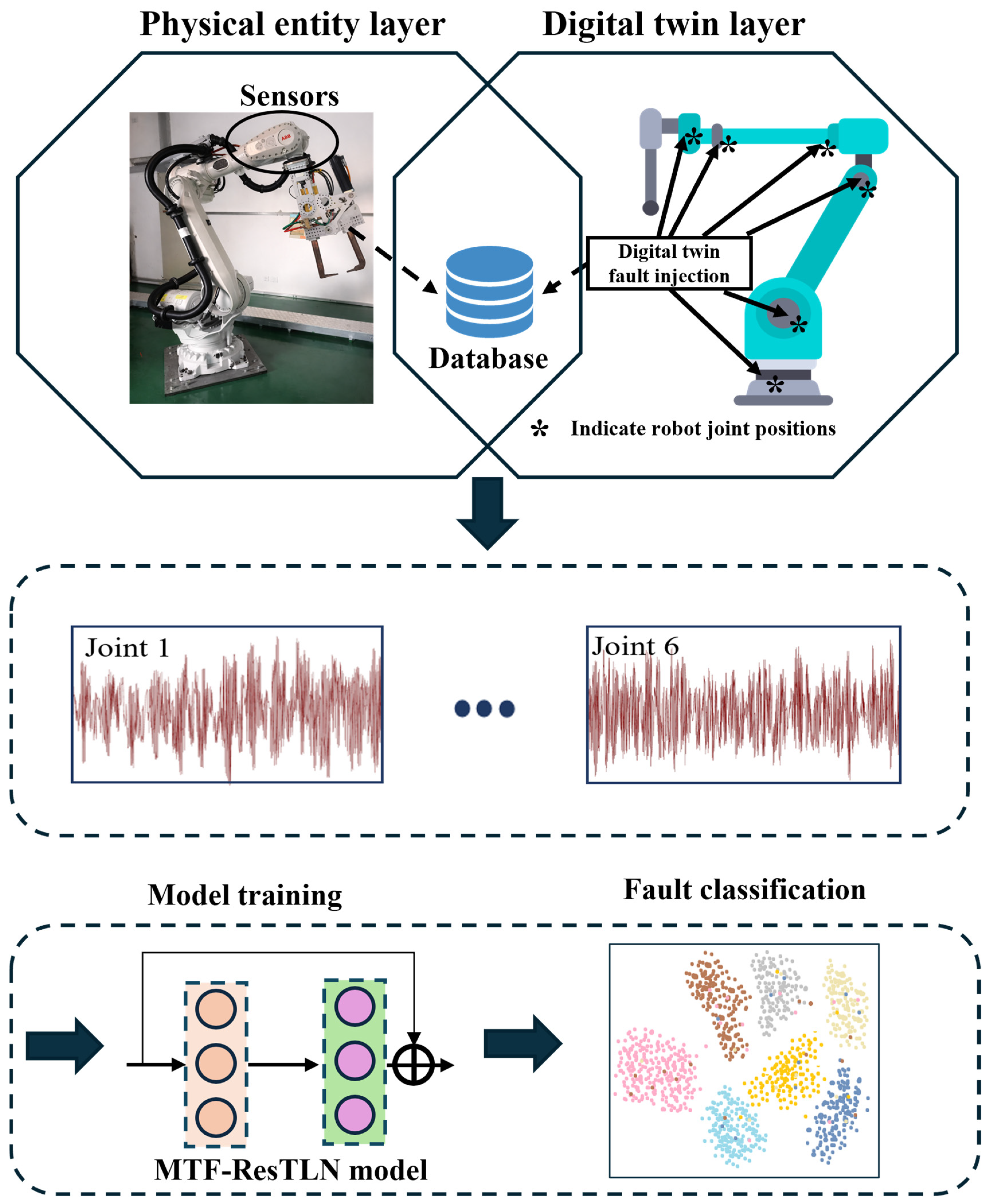
To address the aforementioned challenges, this study proposes a fault detection method that integrates digital twin technology with data-driven approaches to mitigate the issue of limited data availability. The main contributions of this paper are as follows:
- (1)
This paper proposes a novel fault diagnosis paradigm for scenarios characterized by a “lack of fault samples.” To address the limitations of traditional data-driven approaches, which heavily rely on large amounts of real fault data that are difficult to obtain in practical industrial robots, this study introduces digital twin technology. High-fidelity robot models are constructed in a virtual environment, and multiple types of fault data are generated via a mechanism-driven approach. This enables fault diagnosis modeling with only a limited number—or even none—of real fault samples. The proposed method overcomes the dependency of conventional diagnostic techniques on fault data, significantly enhancing its applicability in real-world engineering contexts.
- (2)
A physics-mechanism-constrained virtual–real data generation method is developed. Unlike traditional approaches based on idealized models or simple data augmentation, this study analyzes bearing fault excitations and injects faults into the digital twin model in a physically consistent manner. The simulated fault data are then fused with measured healthy data to construct a dataset that more closely approximates the real operational distribution, effectively mitigating the domain shift between simulated and actual data.
- (3)
A fault diagnosis model, MTF-ResTLN, is proposed for scenarios with limited samples and cross-operating conditions.
The model encodes one-dimensional vibration signals into two-dimensional temporal feature images using the Markov Transition Field, enhancing feature representation capability. Simultaneously, by integrating a residual transfer learning network with a domain adaptation mechanism, the model aligns features between the source domain (simulated data) and the target domain (real-world data), significantly improving diagnostic accuracy and robustness under conditions of scarce fault samples or varying operating scenarios.
The remainder of this paper is organized as follows:
Section 2 presents the overall framework and methodology;
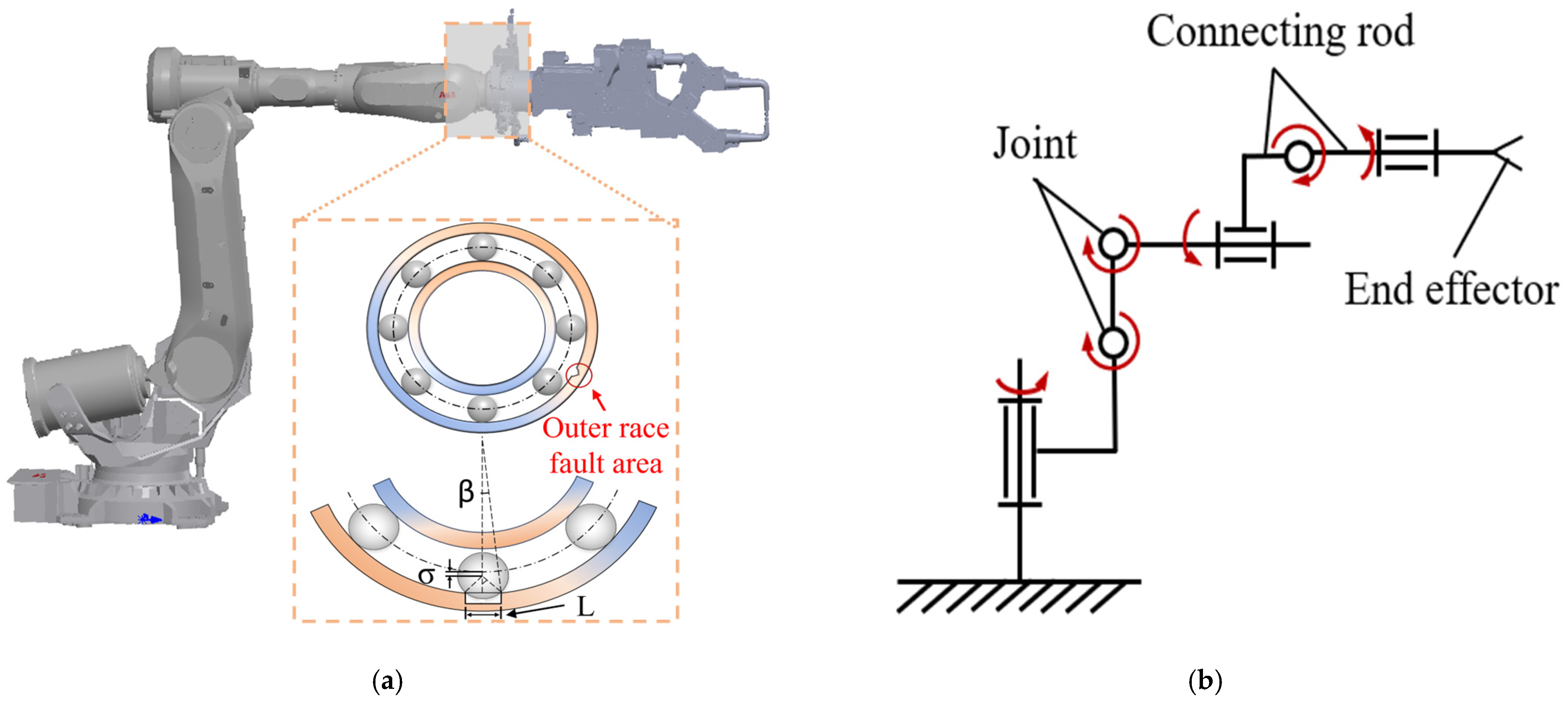
Section 3 introduces the fault mechanisms of rolling bearings and analyzes the associated fault-induced forces;
Section 4 describes the construction of the robotic test platform, the development of the digital twin model, and the acquisition and evaluation of vibration signals using the proposed MTF-ResTLN model, along with a comparative analysis of fault diagnosis methods; finally,
Section 5 provides a comprehensive summary of the findings of this study.
4. Experiment
To validate the practicality of the proposed fault detection method that integrates digital twin technology with the MTF-ResTLN method, an experimental platform for robot joint motion was established. In this section, a digital twin model of a physical robot is developed for simulation and analysis. The fault states of the bearings are analyzed, and fault excitation is injected into the digital twin model. The vibration signals simulated by the digital twin model are evaluated against experimentally acquired signals. Furthermore, the classification accuracy of the digital twin model is verified under various conditions, and a comparative analysis with alternative fault diagnosis methods is provided.
4.1. Experimental Platform Construction
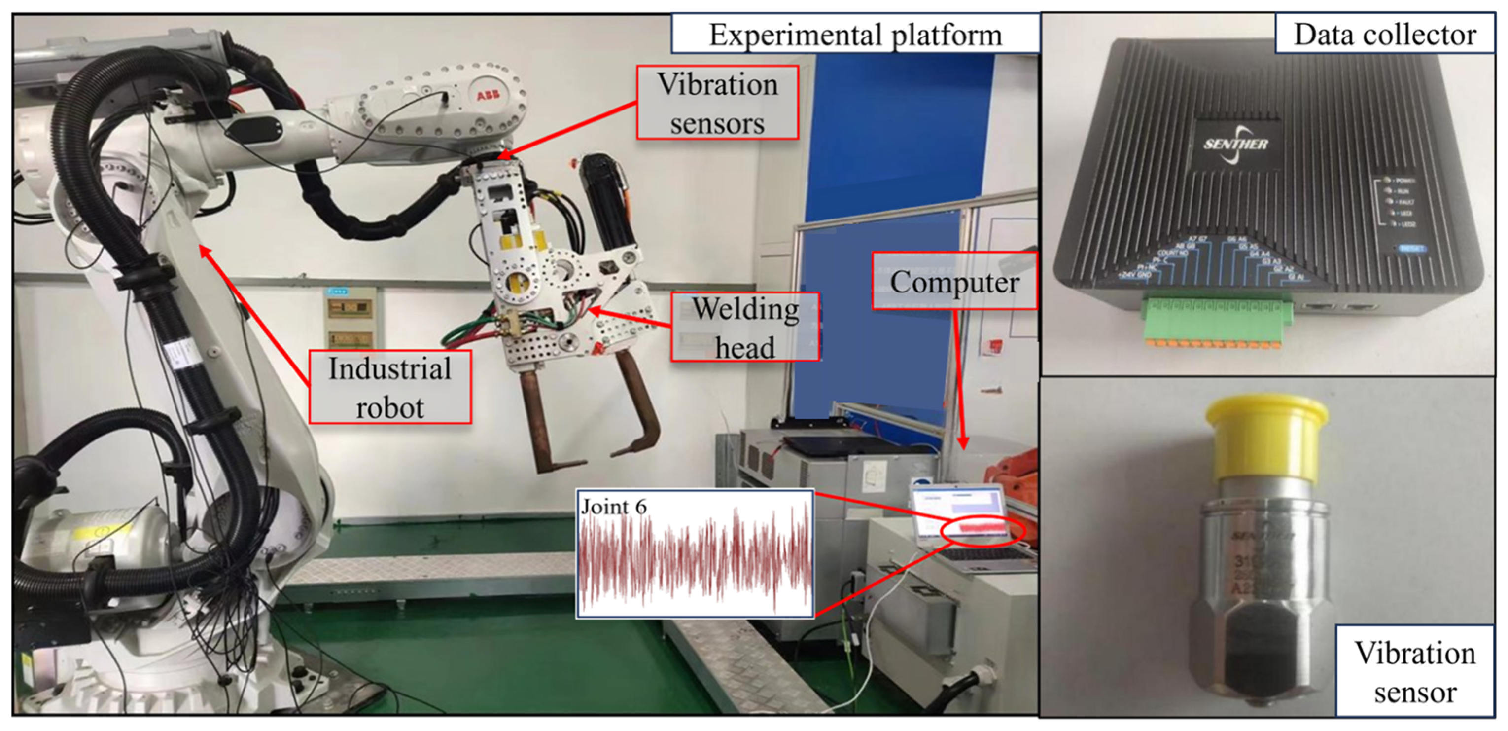
To evaluate the effectiveness of the proposed method, a test platform was established, as shown in
Figure 4. The experimental setup consists of a six-axis articulated robot (ABB IRB 6700 ABB (China) Co., Ltd., Beijing, China), an accelerometer (310 A-20 Connection Technology Center (CTC) New York, NY, USA), a data acquisition unit, and a laptop computer. The final joint of the robot is connected to an X-shaped welding fixture serving as the end-effector, which plays a critical role in the execution of welding tasks.
As shown in
Figure 4, an accelerometer is installed at the end joint of the robot to collect vibration data. The fault data of each joint generated by the digital twin model are utilized to construct the training dataset.
Since multi-joint failure modes are relatively rare, the experiments focus only on simulating single-joint failure modes. The objective is for the proposed model to promptly identify and diagnose single-joint faults, thereby preventing their progression into more severe multi-joint failures in practical applications.
The dataset consists of seven states, labeled from 0 to 6. State 0 represents a healthy joint condition, while states 1 to 6 correspond to different types of joint faults. Each sample is composed of a one-dimensional time series, where each data channel corresponds to the vibration signal generated by the end joint.
It should be noted that, during the experimental data acquisition process, only a single sensor was installed at the robot’s end joint, rather than employing a multi-sensor array. This design is based on the kinematic characteristics of the serial structure of industrial robots: the motion states of each joint are transmitted sequentially through the transmission chain and ultimately reflected in the response of the end effector. Therefore, the vibrations and posture changes at the end joint can comprehensively characterize the overall dynamic behavior of the six-degree-of-freedom (6-DoF) system [
51].
Specifically, the three-axis vibration signals captured by the single sensor reflect motion information along the three spatial directions and, under the system’s coupling effects, implicitly encode the operating states of each joint bearing. The resulting signal framework can simultaneously represent: three translational degrees of freedom (vibrations along x, y, and z axes) and three rotational degrees of freedom (posture angle variations), thereby achieving a unified description of 6-DoF motion information. When a joint bearing experiences a fault, the resulting impact loads and characteristic frequencies propagate along the transmission path and manifest in the end vibration signals as changes in amplitude and spectral structure. By integrating multi-condition data generated from the digital twin model, the distinguishability of fault features across different joints can be further enhanced.
Thus, under the premise of preserving information integrity, the single-sensor scheme not only reduces the complexity and cost of the experimental system but also provides a unified and effective data foundation for subsequent data-driven modeling.
4.2. Digital Twin Modeling of Industrial Robots
4.2.1. Digital Twin Model Construction
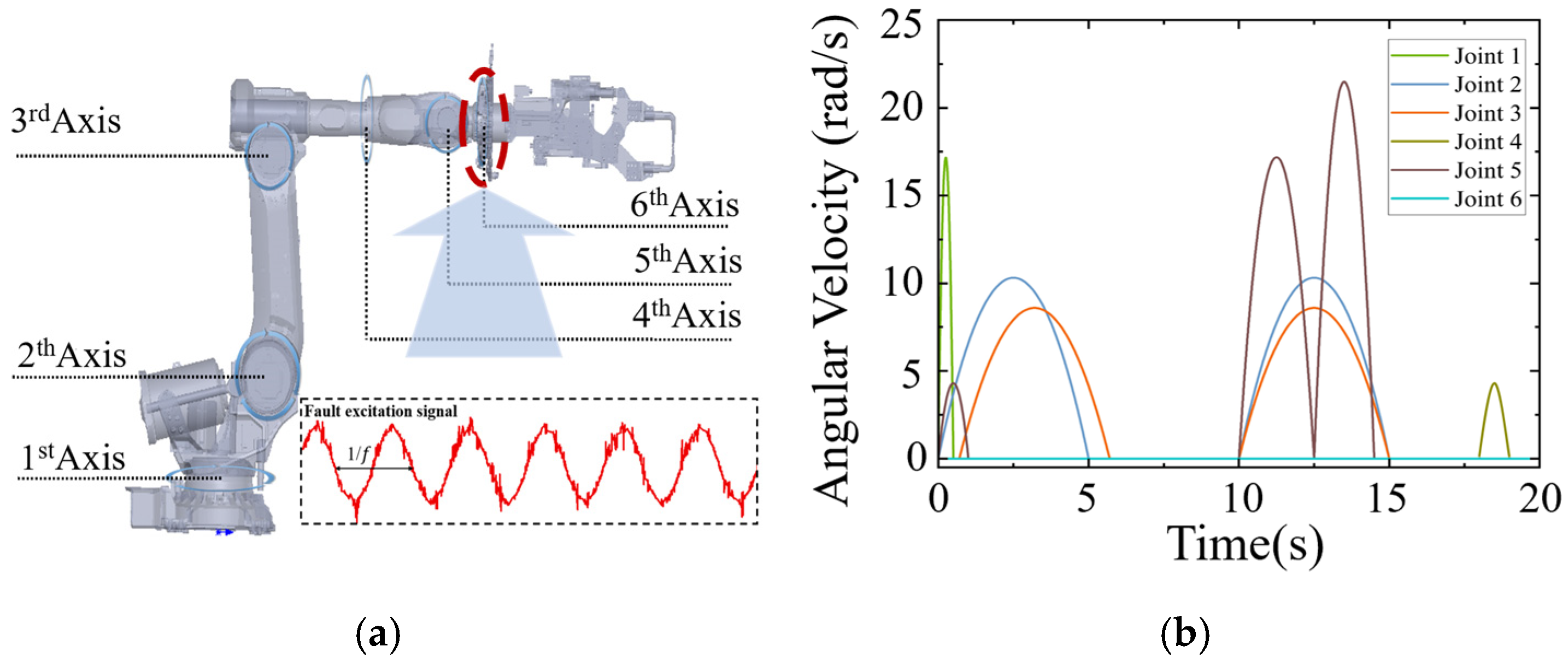
The digital twin model of the articulated robot is constructed using an object-oriented approach to ensure model consistency. For example, the mechanical system can be decomposed into components such as the articulated robot platform, robotic arm, and welding gripper. In this manner, the specific type of each component is determined through a hierarchical structure. Subsequently, the three-dimensional models of these components are assembled and imported into the multibody dynamics simulation software ADAMS to establish the mechanical geometric model of the articulated robot. The material properties of the objects are first defined and their names are standardized. Based on the analysis of the robot’s 3D model, and in accordance with the actual rotational substitutions, actuator positions, and primary motion constraints of the welding robot, motion constraints are incorporated into the model to construct the digital twin. As a result, the dimensions, material properties, and operating conditions of the twin model correspond accurately to those of the physical robot, as illustrated in
Figure 5a.
The motion is described by the angular displacements of the six joints, which characterize its operating state. In practical industrial applications, robots typically perform a set of predefined motions repeatedly. In this study, the motion cycle has a duration of 20 s; therefore, the motion profile for one cycle is illustrated in
Figure 5b.
4.2.2. Validation of Digital Twin Model
During the validation of the digital twin model, the experimental conditions were designed for the robot to perform a series of typical tasks on the experimental platform. The trajectories of these tasks cover the main workspace of the robot, involving various postures and motion speeds under different joint combinations. For each task, torque signals from all robot joints were collected, and each experiment was repeated multiple times to ensure data reliability and repeatability. Torque signals were chosen as the validation metric primarily because of their high sensitivity to changes in load and operating conditions, as well as their ease of real-time acquisition, aligning with the requirements of practical engineering applications.
Based on the Lagrange equation, the kinetic model can be expressed as follows.
where
are the driving moments, where
and
represent the driving moments exerted on the lumbar and basal joints, while
refer to the driving moments applied to each joint of the parallel mechanism. The variables Ek and Eu represent the aggregate kinetic and potential energies possessed by the robot. The expressions of
and
can be formulated as follows:
where
represents the inertia tensor of the
-th linkage in relation to the base coordinate system,
denotes the mass of the
-th linkage, and g corresponds to gravitational acceleration. The formula can be reformulated as:
where
represents the inertia matrix,
denotes centrifugal and Coriolis effects, while
signifies gravitational forces.
Industrial robots do not employ lightweight links in order to ensure stable operation; consequently, their components possess relatively large masses. In comparison, the effects of Coriolis and centrifugal forces are relatively small and are therefore neglected in this study. Based on the above dynamic equations and the actual operating postures of the robot, the driving torques corresponding to each joint under specific working conditions were calculated. Considering that torque signals are highly sensitive to load and operating condition variations and can be conveniently acquired in real time in practical engineering applications, the validity of the digital twin model and the feasibility of the dual-model approach were verified through joint torque comparison.
To validate the accuracy of the digital twin model, simulation data and experimentally measured data were compared under identical motion trajectories. The ABB IRB6700 industrial robot was programmed to execute a predefined cyclic trajectory with a motion period of 20 s, covering representative operating states within the robot workspace. By simulating these working conditions, the torque responses of each joint over the complete motion cycle were obtained.
During the experiments, the actual joint torque signals of all six joints were directly acquired from the robot controller through the ABB RobotStudio interface and synchronously compared with the simulated torque outputs generated by the ADAMS digital twin model. Meanwhile, vibration signals were collected using an accelerometer mounted at the robot end-effector. It should be noted that the vibration signals were mainly used for the subsequent training and testing of the fault diagnosis model, whereas the joint torque signals were specifically employed to validate the consistency between the digital twin dynamic model and the physical robot.
To reduce random disturbances and ensure experimental repeatability, each operating condition was repeated five times. The effectiveness of the digital twin model was evaluated by comparing the waveform trends, peak amplitudes, and temporal response characteristics of the simulated and experimentally measured torque signals over the complete motion cycle.
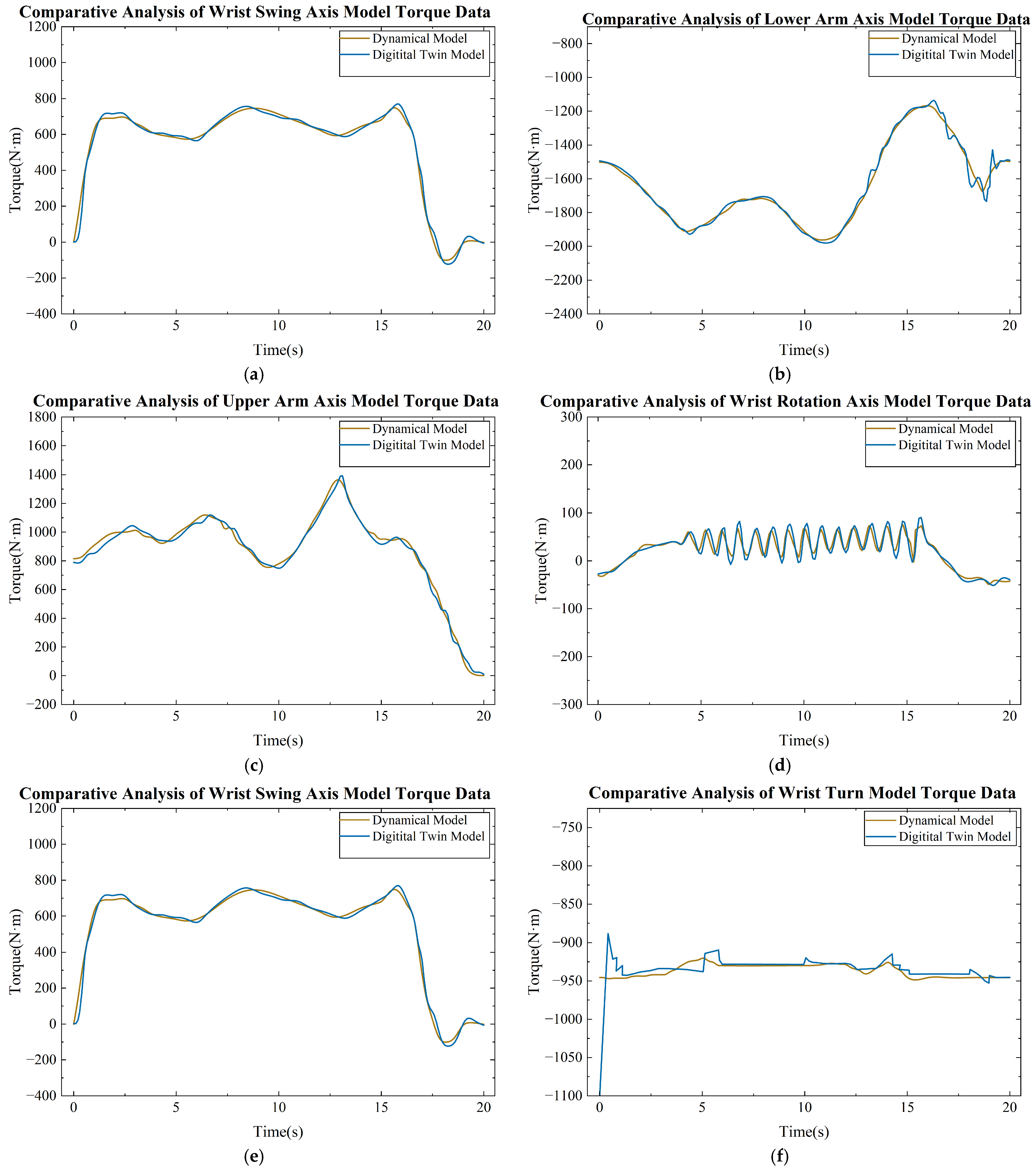
Figure 6 presents the comparison results of the robot joint torques varying with time, which were used to verify the predictive accuracy of the digital twin model under typical task trajectories. By comparing the joint torque signals predicted by the model with the experimentally measured joint torque signals, the fitting capability of the model and its accuracy in representing key operational characteristics were evaluated.
As shown in
Figure 6, the results indicate that the joint torques predicted by the dual-model approach are highly consistent with the simulations of the dynamic model, demonstrating high accuracy under these operating conditions. This consistency is not only reflected numerically but also in the precise capture of torque variation trends, highlighting the dual model’s superiority in simulating the dynamic behavior of complex systems. It effectively reflects system responses and provides reliable predictions.
To further validate the digital twin model’s capability in representing the actual operational behavior of industrial robots, acceleration and torque data from each joint were collected on the robot experimental platform and compared with the model predictions. The results show a high agreement between the digital twin predictions and measured data, with correlation coefficients (R2) of key operational characteristics exceeding 0.95. This indicates that the model is not only effective in numerical simulation but also accurately reflects the real operational characteristics of industrial robots, providing a reliable simulation foundation for subsequent fault diagnosis experiments.
4.3. Fault Dataset Acquisition
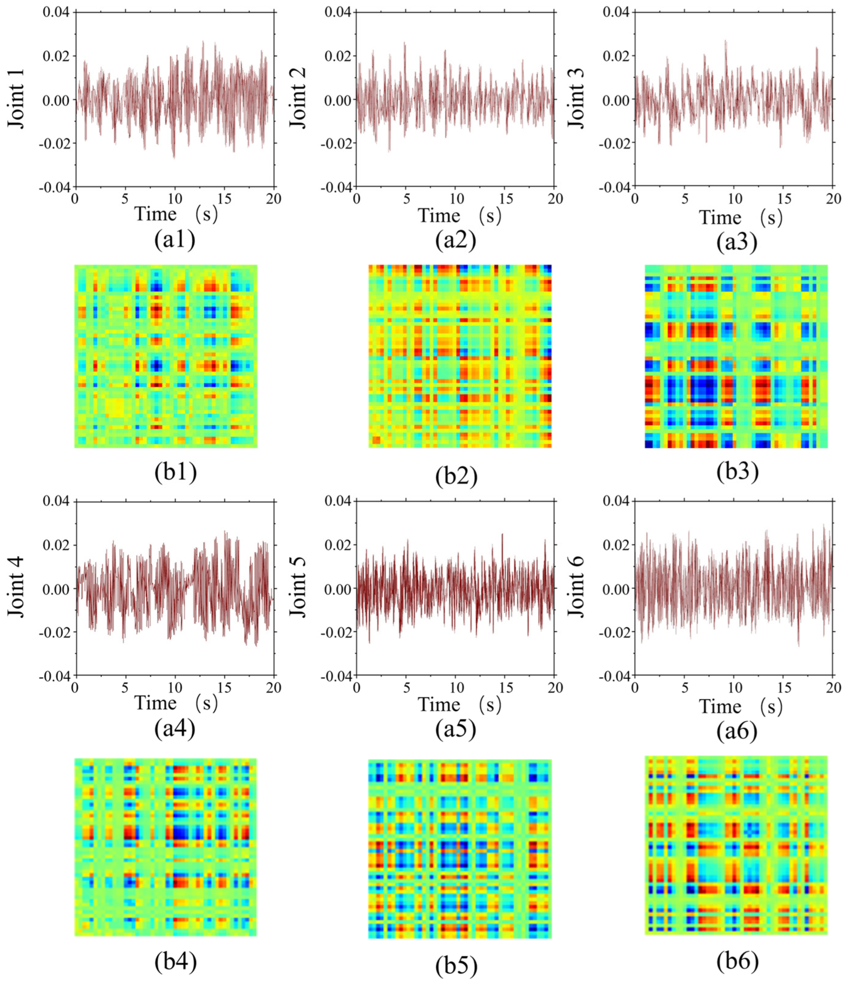
By applying fault excitation to different joints, the motion states of each joint under fault conditions are simulated, and the corresponding vibration signals are obtained.
Figure 7 illustrates the vibration signals of joints with various defects.
In this study, the collected dataset is systematically divided into training, validation, and testing sets. Specifically, 70% of the data is allocated for training, 20% for validation, and the remaining 10% for testing. Each condition consists of 750 data segments, with each segment containing 10,000 data points. After applying a sliding window technique, the total number of samples reaches 33,750. The detailed distribution of the dataset is presented in
Table 4.
In this manner, data associated with different labels can be obtained and used to train the fault diagnosis algorithm. Furthermore, the health condition of each joint of the robot can be evaluated by analyzing the vibration signals generated by the actual robot using the trained model.
4.4. Model Training
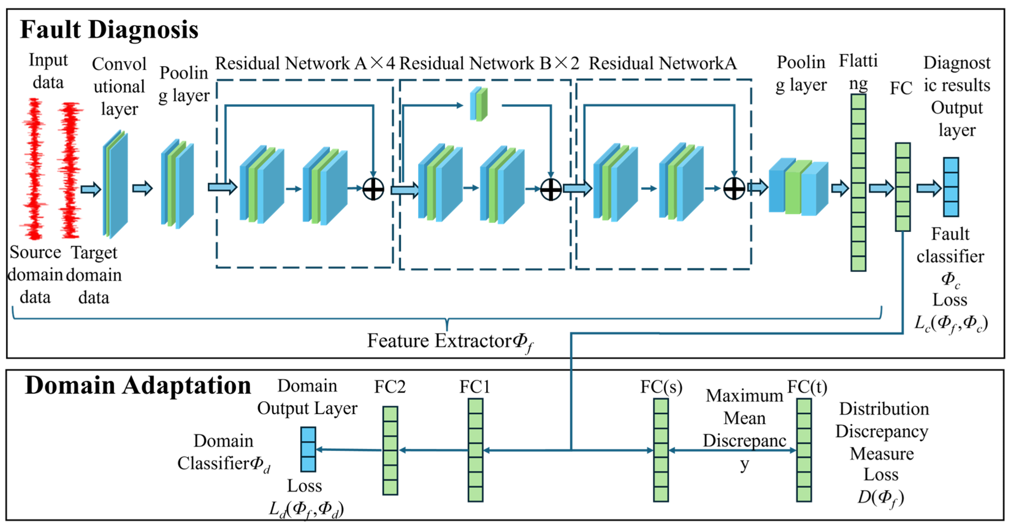
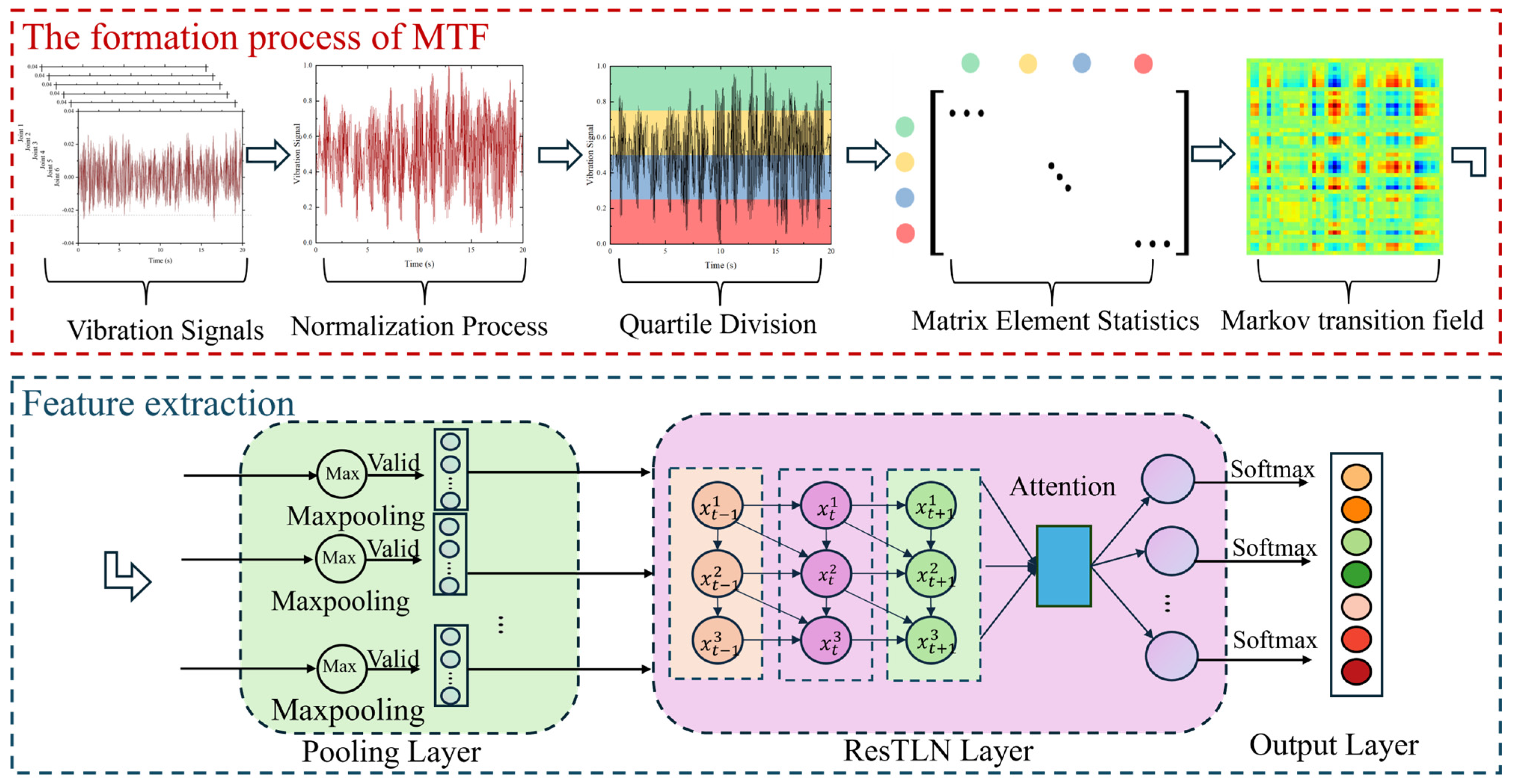
The overall architecture of the model consists of two main components: the construction of the Markov Transition Field and feature extraction, as illustrated in
Figure 8. Specifically, during the time-domain feature extraction stage, the Markov Transition Field is employed to extract features from the vibration signals of each joint of the industrial robot. The core function of MTF is to transform short segments of vibration signals into two-dimensional representations, thereby encoding temporal correlations within the data. This approach enables MTF to preserve the intrinsic characteristics of the original signals while reducing noise interference, thus ensuring the accuracy of feature extraction in subsequent modeling stages.
Subsequently, a Residual Transfer Learning Network is employed to perform hierarchical feature extraction from the time-domain feature images generated by MTF through convolutional operations. By incorporating residual connections and transfer learning, the model enhances feature representation capability, enabling it to effectively identify key features associated with faults. The convolutional operations improve the model’s sensitivity to specific frequency or amplitude variations, which is particularly important for analyzing complex operational data from industrial robots, where convolutional layers can autonomously detect meaningful fault patterns. Furthermore, ResTLN reduces feature dimensionality while preserving the most discriminative features through convolutional down sampling, stride convolution, pooling operations, and global average pooling, thereby lowering computational complexity.
In the stages of feature learning and fault classification, the ResTLN further performs deep learning on the initially extracted features. By incorporating residual connections, the network effectively addresses the degradation problem in deep architectures while preserving low-level feature information, thereby enabling multi-level nonlinear transformations. Consequently, the original low-level features are progressively abstracted into high-level semantic representations with enhanced discriminative capability, significantly improving the model’s ability to characterize complex fault patterns.
Furthermore, by introducing a transfer learning strategy, feature representations and parameter knowledge learned from the source domain are transferred to the target fault diagnosis task. This process effectively mitigates distribution shift issues caused by limited target domain samples and varying operating conditions by aligning the feature distributions between the source and target domains, thereby significantly reducing the risk of model performance degradation. Related studies indicate that combining subdomain distribution alignment with discriminative feature enhancement mechanisms can achieve cross-domain consistency while improving inter-class separability, thus enhancing the model’s generalization ability and robustness under complex operating conditions.
On this basis, the high-level features output by ResTLN are further fed into an attention mechanism module. This module jointly models temporal and spectral features, adaptively assigning weights according to the contribution of different channels and feature dimensions to fault recognition. This process emphasizes critical fault information while suppressing redundant noise. Existing research has shown that time–frequency feature attention mechanisms can effectively capture the local temporal characteristics and frequency-domain energy distribution of non-stationary vibration signals, and dynamically weight different directions in multi-axis signals according to their sensitivity differences, thereby significantly improving feature representation capability [
52]. Consequently, this mechanism enables the model to focus more on core features highly relevant to fault discrimination, further enhancing the accuracy and stability of fault identification.
Finally, based on the weighted feature representations, a Softmax classifier is employed to determine the fault categories and output the probability distribution for each fault class, thereby achieving accurate identification of robot fault types. The specific parameters of the model are listed in
Table 5 and
Table 6.
The network adopts identity mapping as the shortcut connection, and the activation function is ReLU. During model training, the learning rate is set to 0.001, and the Adam optimizer is used for parameter updates.
4.5. Implementation Details
To ensure the reproducibility and transparency of the proposed method, all key implementation details and hyperparameters are explicitly reported in this subsection.
The proposed MTF-ResTLN model is implemented in Python 3.8 using the TensorFlow 2.16 framework. All experiments are conducted on a workstation equipped with an NVIDIA RTX 3060 GPU.
The model is trained using the Adam optimizer with an initial learning rate of 1 × 10⁻³. The batch size is set to 32, and the maximum number of training epochs is 100. An early stopping strategy is adopted based on the validation loss, with a patience of 10 epochs to prevent overfitting.
To enhance generalization performance, L2 regularization (weight decay) with a coefficient of 1 × 10⁻⁴ is applied. In addition, dropout with a rate of 0.5 is introduced in the fully connected layers. All network weights are initialized using the He normal initialization method.
The dataset is divided into training, validation, and test sets with a ratio of 70%, 20%, and 10%, respectively. The model with the best validation performance is selected for final evaluation.
To ensure robustness and reduce the impact of randomness, all experiments are repeated five times with different random seeds, and the reported results correspond to the average values.
The detailed hyperparameter settings are summarized in
Table 7.
4.6. Prediction Using Test Dataset
The test dataset is used to evaluate the effectiveness of MTF-ResTLN in accurately predicting the health status of unseen instances. Common performance metrics used for classification include accuracy, recall, and F-score. The subsequent section provides a detailed explanation of these metrics.
Precision: The proportion of predicted anomalous instances that are actually anomalous.
where
,
, and
FN denote the numbers of false positives, true positives, and false negatives, respectively.
Recall: The ratio of correctly classified anomalous instances to the total number of actual positive instances.
Accuracy: The ratio of correctly classified instances to the total number of instances.
where
denotes the number of true negatives, i.e., instances that are correctly predicted as normal.
F-score: This is the harmonic mean of precision and recall, and it is typically closer to the lower value between the two. Therefore, it provides a more realistic evaluation of classification performance by considering both correctness and completeness. The effectiveness of the F-score is further enhanced when there are different costs associated with false positives and false negatives.
Table 8 presents the statistical metrics for evaluating the dataset. The model correctly classifies 98% of vibration signals under normal operating conditions and achieves accuracies of 97%, 96%, and 96% in predicting vibrations caused by single-axis, dual-axis, and triple-axis faults, respectively. For four-axis, five-axis, and six-axis fault-induced vibrations, the prediction accuracies reach 95%, 93%, and 92%, respectively. These results demonstrate that the proposed method effectively addresses the issue of insufficient fault data, enabling the training of a reliable fault detection model that can be applied to the prediction of new data.
4.7. Ablation Experiment Design and Analysis
To further validate the effectiveness of each component in the proposed method, ablation experiments were conducted under a unified experimental setup. It should be noted that the digital twin module not only forms a part of the methodological framework but also serves as a crucial source of fault data. Direct removal of this module would result in a severe shortage of training data, rendering effective training of the deep learning model infeasible. Therefore, in the ablation experiments, the digital twin data generation mechanism was retained, and the study focused on validating key mechanisms at the model architecture level, specifically feature extraction, cross-domain alignment, and feature weighting.
Based on the considerations above, this study designed the ablation experiment scheme shown in
Table 9, focusing on the three core components of the ResTLN model—Residual Network (ResNet), Transfer Learning, and Attention Mechanism.
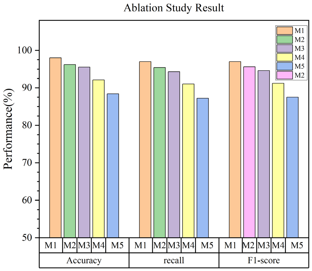
As shown in
Figure 9, the proposed model (M1) achieves the best performance across all evaluation metrics. When individual components are removed, the model performance consistently degrades, indicating the effectiveness of each module.
- (1)
Attention mechanism ablation analysis: in Model B, the attention mechanism was removed to evaluate its impact on feature representation. Theoretically, the attention mechanism assigns differentiated weights to various features, highlighting fault-relevant key information while suppressing noise interference. Related studies have shown that attention mechanisms can significantly enhance a model’s discriminative capability in complex signal environments. Experimental results indicate that, compared with the full Model A, Model B exhibits a decrease in classification accuracy. This demonstrates that, in the presence of noise and redundant information in vibration signals, the attention mechanism effectively strengthens feature representation, thereby improving fault diagnosis performance.
- (2)
Transfer Learning Ablation Analysis: In Model C, the transfer learning module (i.e., the domain adaptation mechanism) was removed to evaluate the distribution discrepancy between digital twin data and real-world data. Previous studies have indicated that distribution shifts commonly exist between different operating conditions or data sources, which, if unaddressed, can significantly impair model generalization. Experimental results show that removing transfer learning leads to a notable decline in model performance, particularly with increased instability on the test set. This demonstrates that a distribution gap indeed exists between digital twin data (source domain) and real-world collected data (target domain), and that the transfer learning mechanism can effectively mitigate this issue by aligning feature distributions, thereby enhancing the model’s robustness in practical applications.
- (3)
Collaborative Mechanism Ablation Analysis: in Model D, both the attention mechanism and the transfer learning module were removed, leaving only the ResNet structure, to analyze the synergistic effect between different components. Experimental results show that the performance of this model declined significantly, with a reduction greater than that observed when either module was removed individually. These results indicate that the attention mechanism and transfer learning serve complementary functions within the model—“feature selection” and “distribution alignment,” respectively. When operating collaboratively, they simultaneously enhance feature representation quality and cross-domain adaptability, leading to superior fault diagnosis performance.
- (4)
Residual Network Structure Analysis: in Model E, a shallow CNN was used to replace ResNet to evaluate the role of the deep residual structure in feature extraction. Experimental results show that the shallow model performed significantly worse than the ResNet structure across all metrics. This indicates that the residual network, through the introduction of skip connections, effectively mitigates the vanishing gradient problem in deep network training and enhances feature extraction capability. However, relying solely on the deep structure is still insufficient to achieve optimal performance; it needs to be combined with transfer learning and the attention mechanism for synergistic effect.
- (5)
Comprehensive Analysis: In summary, the ablation experiment results indicate that: The attention mechanism enhances the model’s focus on key fault features, thereby improving classification performance; the transfer learning module effectively reduces the distribution gap between digital twin data and real-world data, enhancing the model’s generalization capability; the residual network provides a foundation for deep feature extraction, but its performance improvement depends on the synergistic interaction with other modules; there is a clear collaborative effect among the three mechanisms (feature extraction, distribution alignment, and feature weighting), with optimal model performance achieved when all three are used together.
Therefore, it can be concluded that the performance improvement of the proposed method does not stem from a single structural modification, but relies on multi-mechanism collaborative optimization. That is, deep feature extraction is combined with transfer learning for cross-domain alignment and integrated with the attention mechanism to enhance feature discriminability, enabling high-precision fault diagnosis under complex operating conditions.
4.8. Comparison with Other Algorithms
Experiments are conducted to compare the performance of the proposed MTF-ResTLN model with several commonly used machine learning (ML) and deep learning (DL) methods that are widely reported in fault diagnosis studies. The model is implemented in Python 3.8 using the TensorFlow framework and the Scikit-learn library. All experiments are performed on a laptop equipped with an NVIDIA RTX 3060 GPU.
The proposed MTF-ResTLN model is compared with representative classifiers, including ResTLN, Convolutional Neural Networks (CNN), Recurrent Neural Networks (RNN), Support Vector Machines (SVM), and K-Nearest Neighbors (KNN). These methods are selected as they represent typical approaches in both traditional ML-based and DL-based fault diagnosis. To ensure a fair comparison, all models are trained and tested under identical conditions using the same dataset. Key hyperparameters, including the optimizer (Adam), learning rate (1 × 10⁻⁵), and loss function, are kept consistent across all models. The CNN model takes raw vibration signals as input, while RNN, SVM, and KNN process the data according to their respective architectures. For the SVM model, a radial basis function (RBF) kernel is adopted with parameters C = 100 and γ = 0.01. The KNN model uses the Manhattan distance metric with the number of neighbors K set to 5.
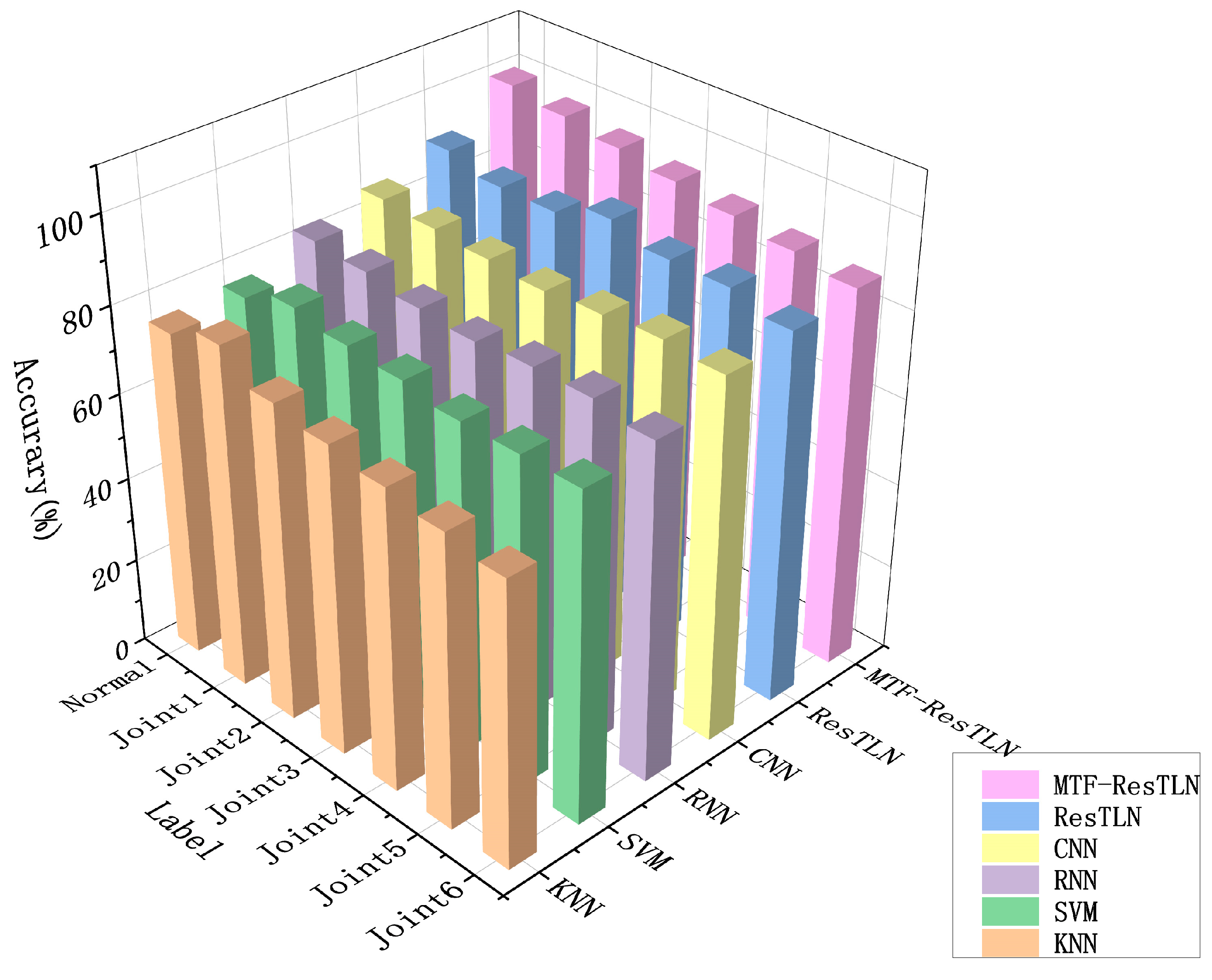
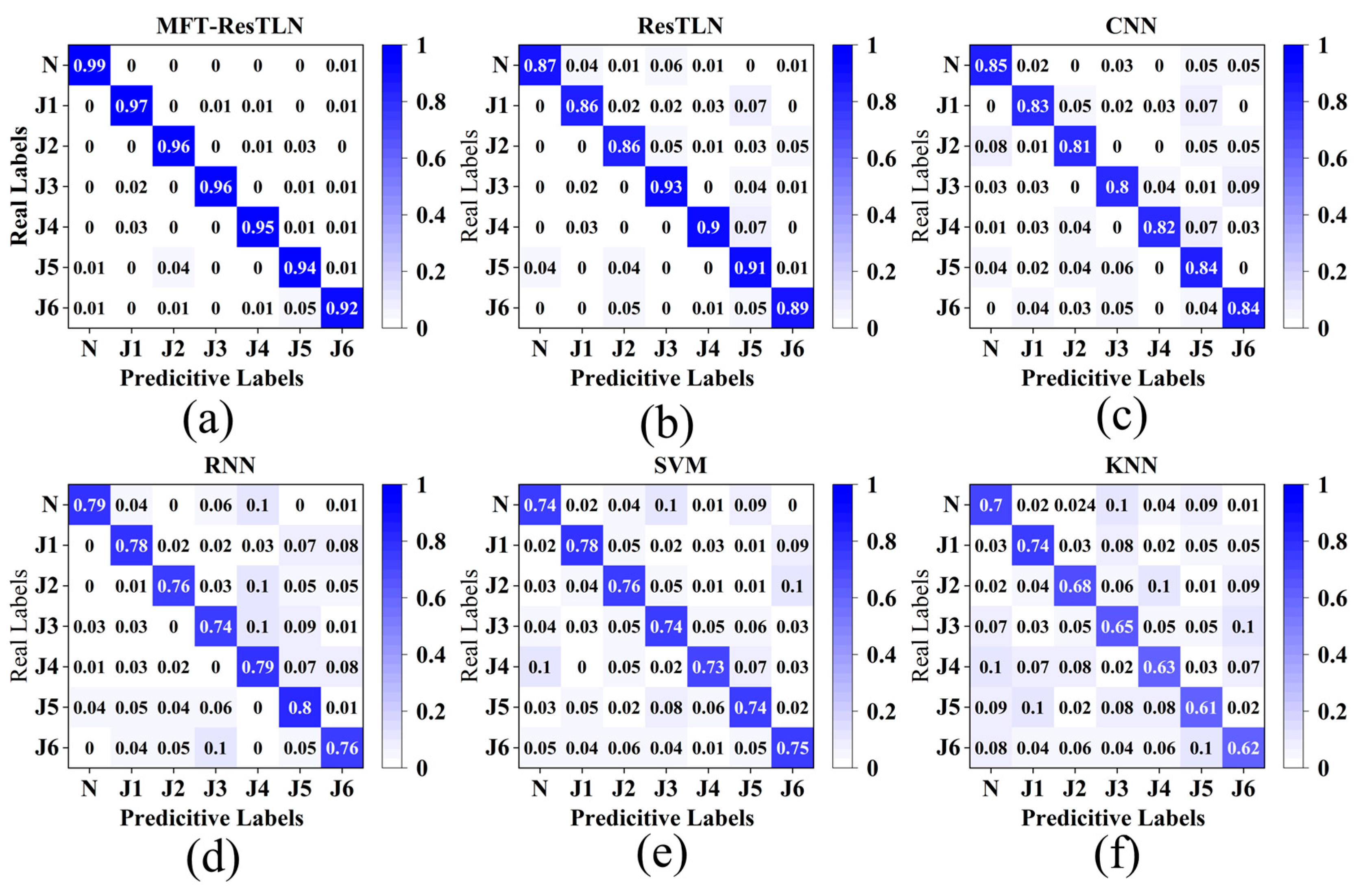
Figure 10 illustrates the overall classification accuracy of each model across seven fault categories, and
Figure 11 presents the corresponding confusion matrices. The results indicate that traditional ML methods such as SVM and KNN exhibit relatively low accuracy, which can be attributed to their limited capability in handling high-dimensional and long time-series data. Among the DL-based models, CNN demonstrates improved performance due to its ability to automatically extract features; however, its performance remains affected by noise and limited data conditions.
In contrast, the proposed MTF-ResTLN model achieves the highest accuracy across all fault categories. This superior performance can be explained from two aspects. First, the MTF-based transformation converts one-dimensional vibration signals into two-dimensional feature representations, effectively preserving temporal dependencies while reducing noise sensitivity. Second, the ResTLN framework integrates residual learning with domain adaptation, enabling robust feature extraction and improved generalization under cross-condition and limited-data scenarios.
Therefore, compared with typical existing methods, the proposed MTF-ResTLN approach not only achieves higher diagnostic accuracy but also provides a more reliable and robust solution for industrial robot fault diagnosis, especially in scenarios with insufficient and heterogeneous data.
To further evaluate the effectiveness of the proposed method, it is necessary to compare it with typical existing fault diagnosis approaches reported in the literature. Traditional machine learning methods such as SVM and KNN are widely used due to their simplicity, but they often struggle with high-dimensional and long time-series data. Deep learning models such as CNN and RNN have shown improved performance by automatically extracting features from raw signals; however, they are still sensitive to noise and require sufficient labeled data.
Compared with these typical methods, the proposed MTF-ResTLN framework demonstrates superior performance on the same dataset. The advantage mainly lies in two aspects. First, the MTF transformation converts one-dimensional vibration signals into two-dimensional representations, which preserves temporal dependencies and enhances feature richness. Second, the ResTLN model incorporates residual learning and domain adaptation, enabling more robust feature extraction and better generalization under limited data conditions.
Therefore, the proposed method not only achieves higher accuracy but also provides a more reliable solution for fault diagnosis in scenarios with insufficient and heterogeneous data.
5. Conclusions
This paper addresses the challenges of limited fault data availability and data imbalance in fault diagnosis of industrial robot joint bearings by proposing a novel method that integrates digital twin technology with MTF-ResTLN, and constructs a complete diagnostic framework. First, a digital twin model of the industrial robot is established, and fault excitation signals are introduced into the model to simulate different joint fault conditions dynamically. This process enables the generation of fault vibration data under multiple operating conditions. By further integrating the simulated fault data with experimentally collected healthy data, a multi-source dataset for model training is constructed, effectively alleviating the issue of insufficient fault samples in practical industrial scenarios. In terms of feature representation, the Markov Transition Field (MTF) is employed to transform one-dimensional vibration signals into two-dimensional feature images with temporal dependencies, thereby enhancing the representation of time-series characteristics and reducing the influence of noise. Based on this, a Residual Transfer Learning Network (ResTLN) is introduced to improve deep feature extraction through residual structures. Meanwhile, a domain adaptation mechanism is incorporated to reduce the distribution discrepancy between source and target domains, which enhances the model’s fault diagnosis capability under cross-domain conditions. Experimental results demonstrate that the proposed method achieves high classification performance across different joint fault diagnosis tasks on the constructed dataset. Specifically, the identification accuracy for normal and faulty states remains at a high level, with overall prediction accuracy ranging from 92% to 98% across different fault categories, verifying the effectiveness and stability of the proposed approach under complex operating conditions.
In this study, the proposed fault diagnosis method demonstrates strong performance under complex operating conditions, and its reliability is well supported by validation using the digital twin model. By comparing the joint torque signals predicted by the digital twin model with experimentally measured data, it is verified that the model can accurately reflect the actual operating characteristics of the robot. Meanwhile, the control and validation of input accuracy in the digital twin model ensure the reliability of simulation results at each stage, thereby guaranteeing the credibility of simulation-based diagnostic outcomes. Overall, from an experimental perspective, the correlation coefficient between the model’s diagnostic results and the actual robot fault diagnosis results reaches 0.97 and an accuracy range of 92–98%. This indicates that the proposed method can still provide accurate and reliable diagnostic conclusions without relying on a large amount of real fault data, offering an effective tool for fault monitoring and predictive maintenance of industrial robots.
Furthermore, comparative experiments with CNN, RNN, SVM, and KNN models show that the MTF-ResTLN model achieves superior overall classification accuracy, indicating that the proposed feature representation and transfer learning strategy can effectively improve fault diagnosis performance.
In summary, by integrating digital twin technology with data-driven methods, this study enables the collaborative utilization of simulated and real-world data, and constructs an effective fault diagnosis model for industrial robots. The proposed approach provides a feasible solution to the problem of insufficient fault data in practical applications.
Although the proposed method has achieved satisfactory results in fault diagnosis tasks, some limitations still remain. The model proposed in this paper requires a long training time due to its large structure and numerous parameters; however, once trained, it meets the time requirements for real-time diagnosis in the field when performing fault diagnosis tasks. Future research will focus on reducing the complexity of the proposed method. Moreover, this study does not specifically address multi-axis simultaneous composite faults. To provide a more comprehensive application framework for industrial robot bearing fault diagnosis, we will conduct more in-depth investigations on this challenging issue in future work.




 ,
,