1. Introduction
Vent holes are indispensable functional features in tire molds because they provide dedicated channels for releasing trapped gases during vulcanization, thereby preventing defects such as air entrapment, incomplete filling, and insufficient local curing in tire manufacturing [
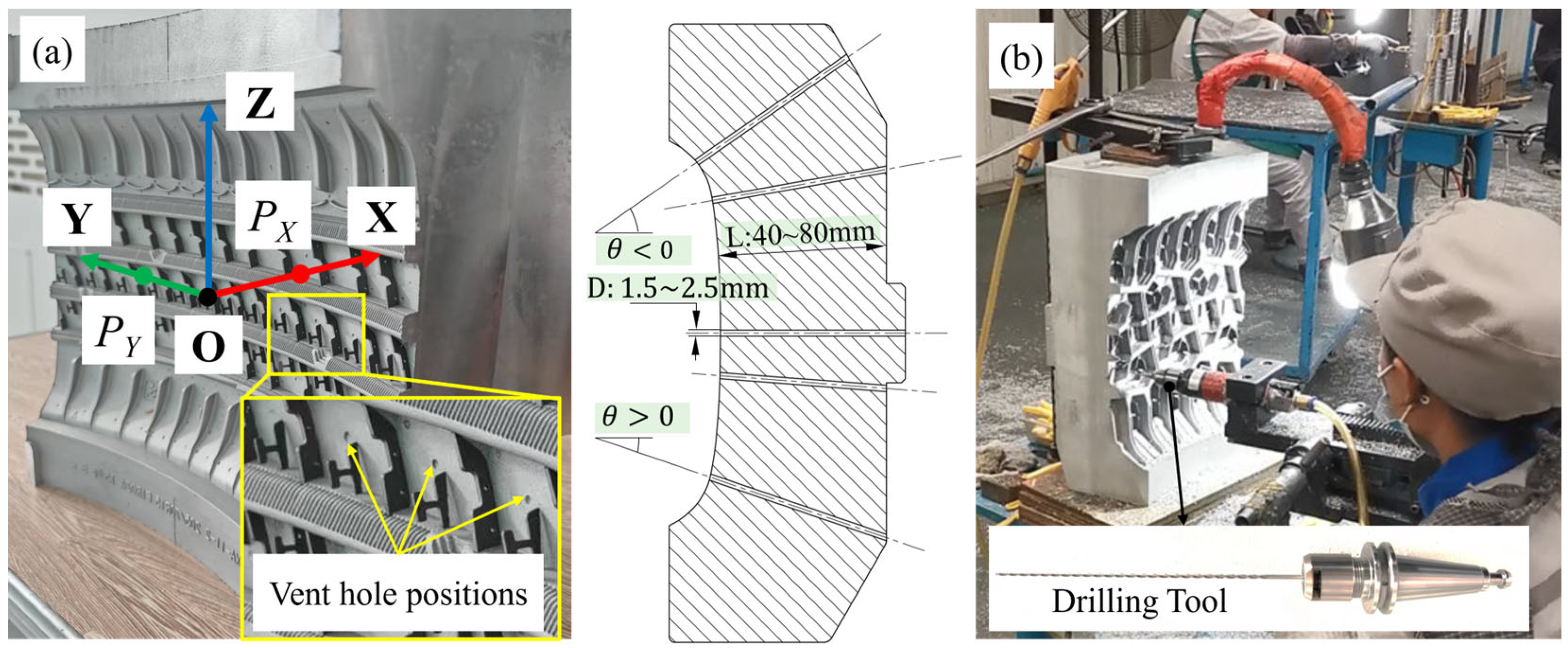
1]. Tire molds are highly customized products and are typically manufactured in a high-mix, low-volume production mode, resulting in substantial variation in their specifications. As shown in
Figure 1a, vent holes generally have diameters ranging from 1.5 to 2.5 mm, with 1.8 mm being the most common. Their depths range from 40 to 80 mm, yielding a relatively large length-to-diameter ratio (L/D) of 25–50, which substantially increases the risk of tool breakage. Moreover, because these holes are distributed over curved surfaces and must be drilled along the local surface normal, the drilling angle varies with position from −10 to 10 degrees. This geometric characteristic further complicates process control and increases the likelihood of tool failure.
In industrial practice, vent-hole drilling is still predominantly performed manually, as shown in
Figure 1b. Operators adjust the feed rate based on tactile feedback and experience to reduce the risks of chip clogging and tool breakage. However, manual drilling presents several disadvantages, including high labor intensity, elevated cost, and potential health hazards for operators. Gun drilling [
2,
3] provides effective chip evacuation and cooling, as well as relatively high process stability, for small-diameter deep-hole machining. However, the machines used for deep-hole drilling are typically dedicated systems, which limits flexibility and results in complex maintenance as well as high equipment and tooling costs. In contrast, industrial robots provide multi-degree-of-freedom motion and a large workspace [
4], offering favorable conditions for the development of flexible robotic drilling systems.
Recent studies have further extended robotic drilling toward multifunctional end-effector design and task planning for complex hole-making applications. For example, Drigalski et al. [
5] developed an end effector with vibration-reduction structures to improve drilling stability. Multifunctional end effectors integrating drilling, helical milling, and other machining operations have also been developed to improve the efficiency and flexibility of automated assembly processes [
6,
7]. In addition, Kong et al. [
8] investigated drilling task planning and offline programming for a robotic multi-spindle drilling system, significantly improving machining efficiency. Nevertheless, most existing studies have focused on shallow-hole drilling in planar workpieces, and their applicability to small-diameter deep-hole drilling remains limited.
Small-diameter deep holes generally refer to holes with diameters below 3 mm and depth-to-diameter ratios greater than 5. Their machining difficulties arise not only from the poor rigidity and limited heat dissipation but also, more importantly, from difficult chip evacuation, which can easily lead to tool breakage [
9,
10,
11,
12]. To address these issues, existing studies have investigated process optimization, cooling and lubrication, and process control. In terms of process optimization, Feng et al. [
13], Li et al. [
14], and Zheng et al. [
15] improved machining performance by optimizing cutting parameters and chip morphology through a combination of experiments, simulations, and regression analysis. In terms of cooling and lubrication, Kumar et al. [
16] investigated the effect of minimum quantity lubrication flow rate on micro-drilling performance of Ti-6Al-4V, while Ganesh et al. [
17] reported that low-temperature coolant can effectively improve hole-wall quality, reduce tool wear and surface roughness, and enhance machining efficiency and sustainability.
Recent studies have increasingly focused on data-driven and hybrid modeling methods for machining-process prediction. For example, physics-based simulation combined with machine learning has been used to improve milling-force prediction accuracy while reducing the number of required experimental tests [
18]. Mechanism-informed GRU models have also been developed for real-time cutting-force prediction using CNC inherent servo signals, demonstrating the potential of recurrent neural networks for modeling nonlinear machining dynamics [
19]. In addition, hybrid models combining CNN, LSTM, self-attention mechanisms, and mechanical force models have been proposed to predict cutting forces under variable machining operations [
20]. Physics-informed Gaussian process regression and generalized tool-wear prediction models have further demonstrated that integrating process signals, physical knowledge, and data-driven learning can improve prediction accuracy and adaptability under varying cutting conditions [
21,
22]. Although these studies have advanced process optimization and auxiliary techniques for small-diameter deep-hole machining, further improvement still depends on the development of intelligent and flexible control methods capable of handling complex and varying machining conditions.
Current drilling control methods are evolving toward intelligent and flexible strategies. Traditional control approaches include PID control [
23], sliding mode control [
24], and adaptive control [
25]. However, these methods generally depend heavily on accurate system models, often involve complex parameter tuning, and exhibit limited noise immunity, real-time capability, and adaptability. Neural-network-based model predictive control (NN-MPC) has emerged as an advanced flexible control strategy [
26]. This strategy has demonstrated promising performance in nonlinear industrial processes, intelligent transportation, and energy systems [
27,
28,
29]. Recent studies have shown that MPC-based methods can provide effective constraint handling and predictive regulation in drilling-related applications, such as directional drilling trajectory control and disturbance suppression [
30,
31]. Nevertheless, these studies mainly focus on geological or petroleum drilling, and their applicability to manufacturing-oriented small-diameter deep-hole drilling remains limited.
Recurrent neural networks, such as LSTM and GRU, are especially suitable for modeling temporal dynamic processes. Huang et al. [
32] proposed an MPC method based on an LSTM neural network, and experiments verified its effectiveness and reliability under different operating modes. For natural ventilation systems, Chen et al. [
33] developed an MPC framework incorporating LSTM models at both fast and slow time scales, significantly improving long-term prediction accuracy. Khosravian et al. [
34] proposed an integrated control framework that combines robust multi-stage MPC with a quantized CNN in a hardware-in-the-loop setting. Their method effectively addressed uncertainties in vehicle dynamics and demonstrated real-time capability, robustness, and scalability on embedded platforms. Collectively, these studies adopted different neural network architectures and MPC-related strategies to accommodate various complex control scenarios, providing useful insights for control research on complex nonlinear processes.
Although recent studies have advanced robotic drilling, deep-hole machining, data-driven process modeling, and MPC-based control, an integrated robotic drilling system and a flexible control method specifically designed for multi-angle small-diameter deep-hole drilling in tire molds are still lacking. Direct application of existing MPC-based methods to this process remains challenging because the feed-torque response depends strongly on drilling angle and chip-evacuation conditions, whereas smooth feed-rate regulation is required to reduce the risk of tool breakage. To address these challenges, this paper develops a robotic drilling system and a GFTMPC-based flexible control method for tire-mold vent-hole drilling by integrating angle-aware feed-torque modeling, reference torque trajectory construction, and constrained MPC-based feed-rate optimization.
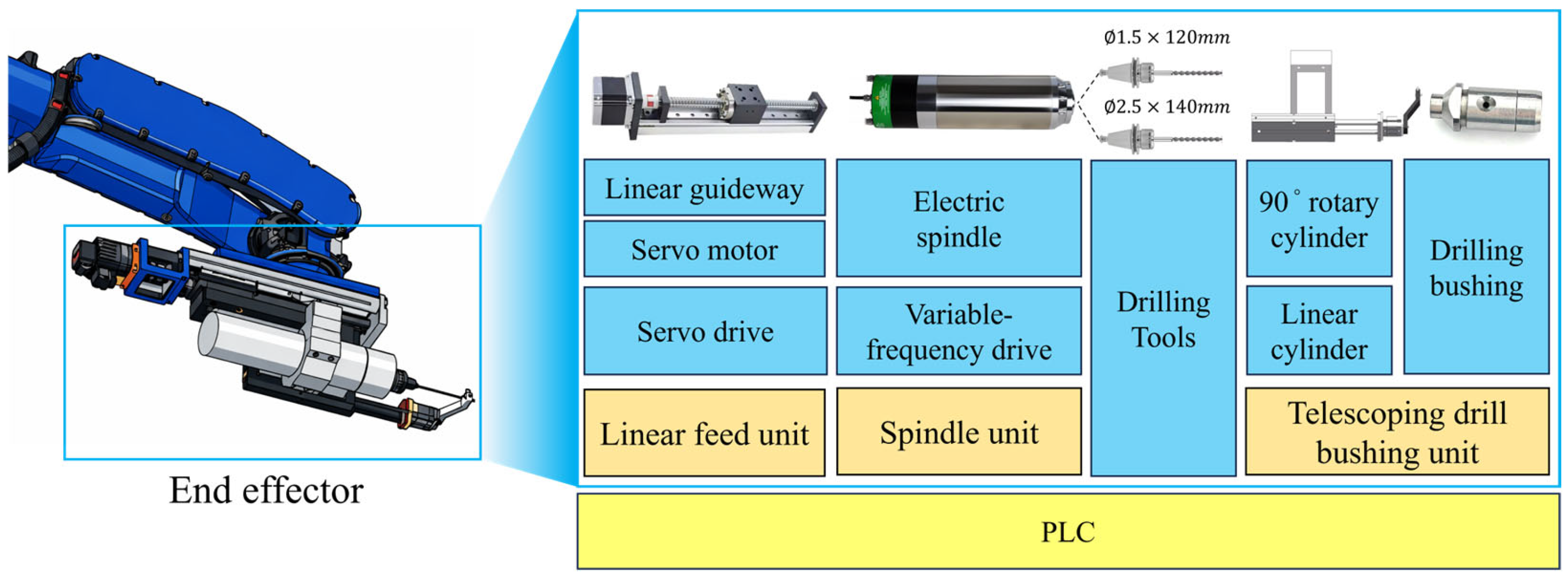
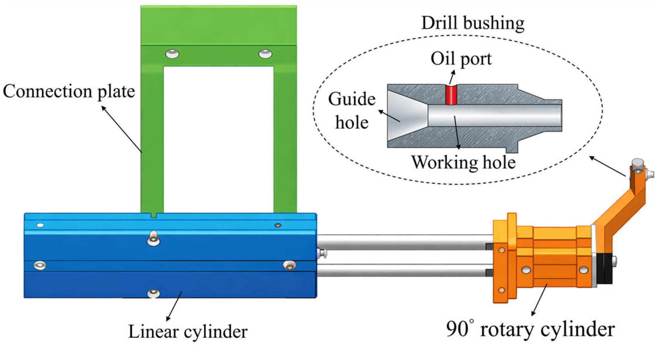
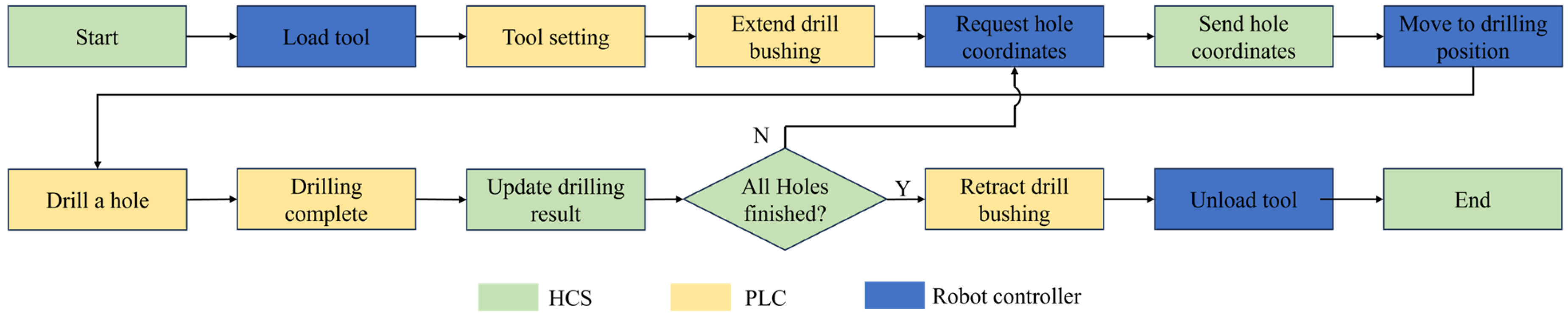
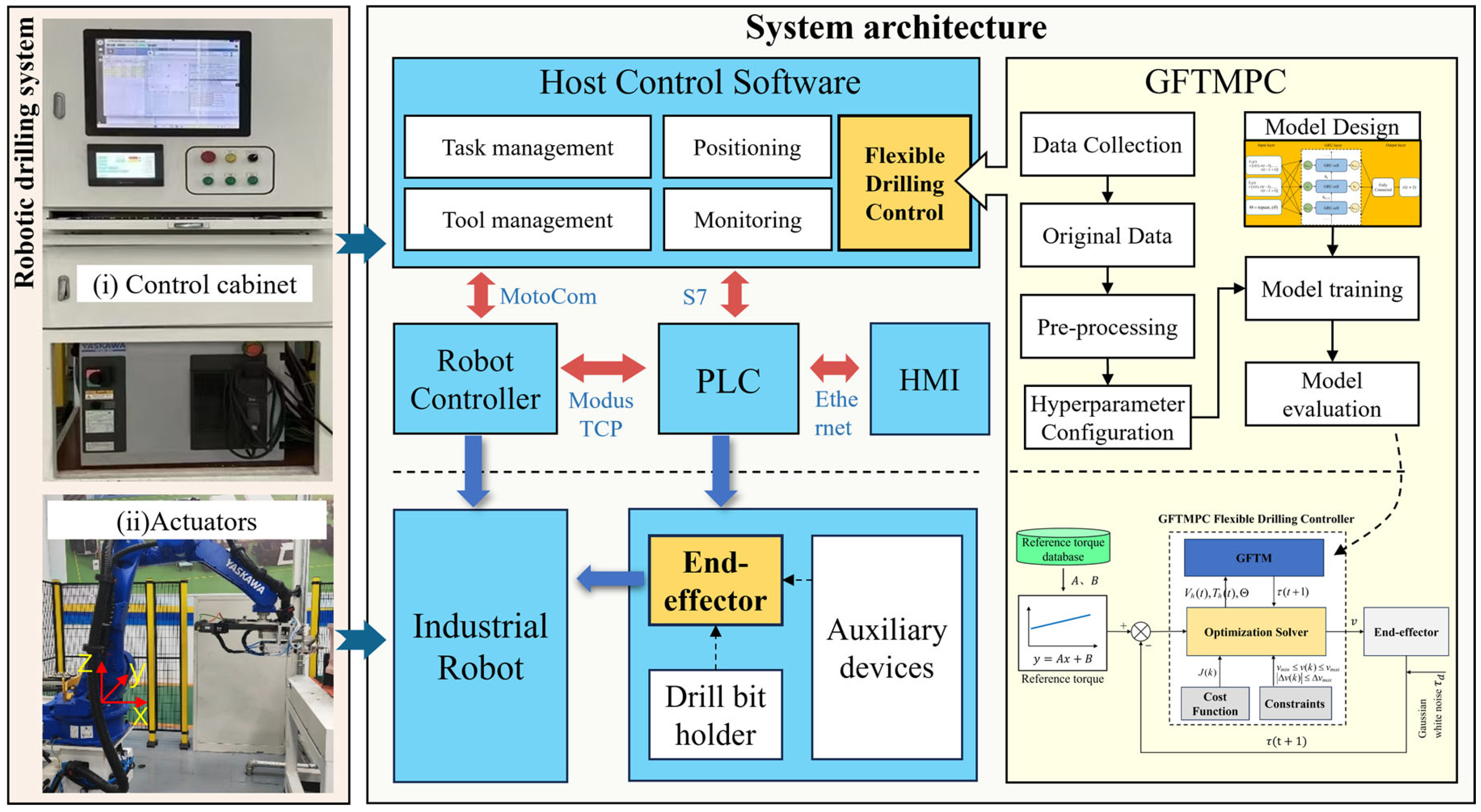
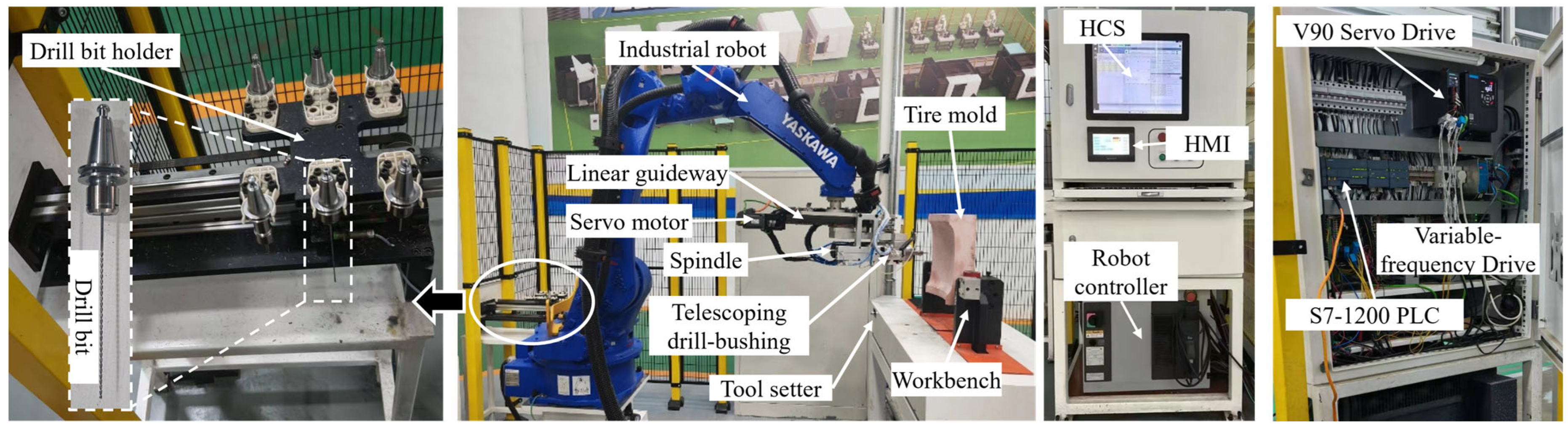
A robotic drilling system was developed for small-diameter deep-hole drilling in tire molds. The system integrates a dedicated drilling end effector with an industrial robot and adopts a hierarchical control architecture to coordinate robot motion, drilling execution, and control-algorithm deployment. It enables automatic drilling, tool setting, and tool changing, thereby supporting flexible and cost-effective vent-hole drilling.
A GFTMPC-based flexible drilling control method was proposed for multi-angle small-diameter deep-hole drilling. The method first formulates the drilling process as a feed-torque-regulated control problem and then constructs an angle-aware GRU feed-torque model using drilling angle, feed rate, and feed torque. On the basis of reference torque trajectories constructed from normal drilling data, the predicted feed torque is embedded in an MPC framework. Feed-rate and feed-rate-increment constraints are incorporated to achieve constrained online feed-rate optimization.
The proposed system and control method were validated through comparative simulations and engineering experiments. A PID baseline was introduced under identical disturbance conditions to evaluate the advantages of GFTMPC in terms of feed-rate smoothness and feed-rate-increment constraint handling. Tool-life comparison experiments and quantitative hole-quality measurements further verified the engineering applicability of the proposed robotic drilling system.
The remainder of this paper is organized as follows.
Section 2 presents the architecture of the robotic drilling system and the design of the end effector.
Section 3 describes the proposed GFTMPC-based flexible control method.
Section 4 presents simulation and experimental results for validating the proposed method.
Section 5 concludes the paper.
3. GFTMPC Flexible Drilling Control
3.1. Analysis of Flexible Robotic Drilling
3.1.1. Comparison of Two Drilling Schemes for Flexible Control Design
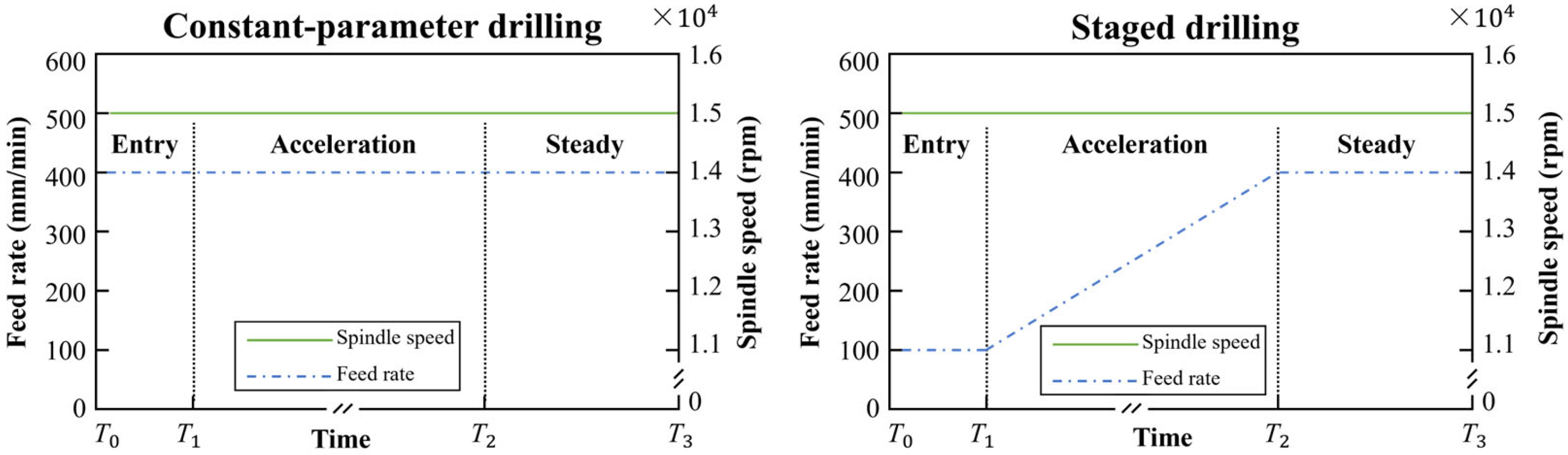
Based on the robotic automatic drilling system developed in this study, a comparative experiment was conducted between constant-parameter drilling and staged drilling, as shown in
Figure 7. The parameters of both drilling modes were selected on the basis of preliminary process tuning and practical production experience so as to provide favorable stability and repeatability. In the constant-parameter drilling mode, the drilling parameters were maintained throughout the entire process, with a spindle speed of 15,000 rpm and a feed rate of 400 mm/min. In contrast, the staged drilling mode divided the drilling process into three stages. In the entry stage, the tool penetrated 3 mm into the workpiece at a feed rate of 100 mm/min. In the acceleration stage, the feed rate was gradually increased at an acceleration of
av = 25 mm/(min·s). In the steady stage, drilling continued at the preset maximum feed rate until the workpiece was fully penetrated.
A total of 100 drilling tests were conducted for each drilling scheme. The drilling angle was fixed at 0°, the drilling depth was 75 mm, and a Φ1.8 × 130 mm drill bit was used. Drill-bushing support and lubrication were applied in all tests. The test results are summarized in
Table 2.
Across the 100 trials, the staged drilling scheme increased the drilling success rate from 81% to 92% and effectively prevented tool breakage during the entry stage. Although the average drilling time increased from 11.2 s to 19.4 s, the improvement in success rate was achieved at a relatively small additional time cost. Overall, the staged drilling scheme performed better than the constant-parameter drilling scheme.
3.1.2. Analysis of Tool Breakage Mechanisms
Although the staged drilling scheme reduced the risk of tool breakage, breakage still occurred during the acceleration and steady stages. Considering both feasibility and cost-effectiveness, the chips generated during drilling and the torque of the feed motor were collected, and the causes of tool breakage were analyzed by comparing chip morphology and feed torque under normal drilling and tool-breakage conditions.
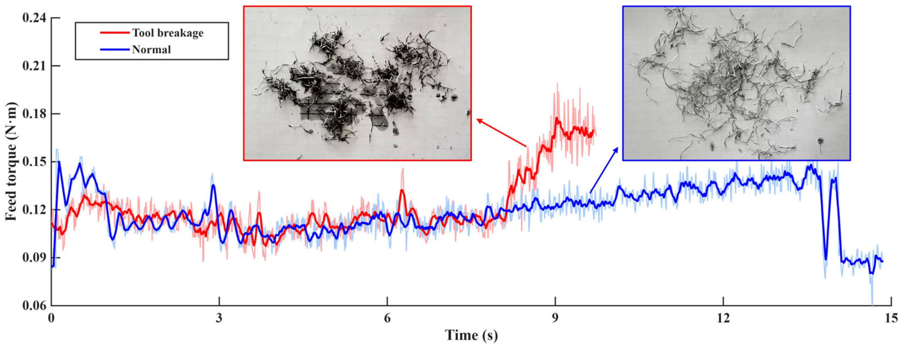
As shown in
Figure 8, the chip morphology observed under normal drilling conditions is relatively uniform, slender, and well dispersed, indicating smooth chip evacuation. In contrast, under tool-breakage conditions, the chips become disordered, curled, and even agglomerated, with obvious accumulation, suggesting obstruction of the chip-evacuation path. During normal drilling, except for the moment when the drill bit initially contacts the workpiece, during which the feed torque fluctuates significantly, the feed torque remains generally stable with only minor fluctuations throughout the remainder of the process. However, prior to tool breakage, the feed torque exhibits a continuous upward trend accompanied by large fluctuations.
The analysis of chip morphology and feed-torque characteristics indicates that tool breakage is primarily caused by poor chip evacuation. Insufficient chip evacuation leads to a continuous increase in feed torque, thereby increasing the tool load and ultimately causing tool breakage. Because tool breakage rarely occurs during the entry stage despite relatively large torque fluctuations, flexible control is applied during the acceleration and steady stages to further reduce the risk of tool breakage.
3.1.3. Problem Formulation for Flexible Drilling Control
The core of flexible drilling control is the adaptive adjustment of the feed rate according to drill-bit load. The feed rate is selected as the control variable and acts directly on the feed motor. Because feed torque reflects both tool load and chip-evacuation conditions, it is used as the feedback variable. This design integrates control and feedback within the feed-drive system, thereby improving system integration while reducing complexity and implementation cost. When chip evacuation is obstructed, the feed torque increases with the tool load. Reducing the feed rate can then decrease the chip-generation rate, alleviate blockage, and prevent further load increase. After chip evacuation recovers, the feed rate is gradually increased to balance drilling efficiency and process stability.
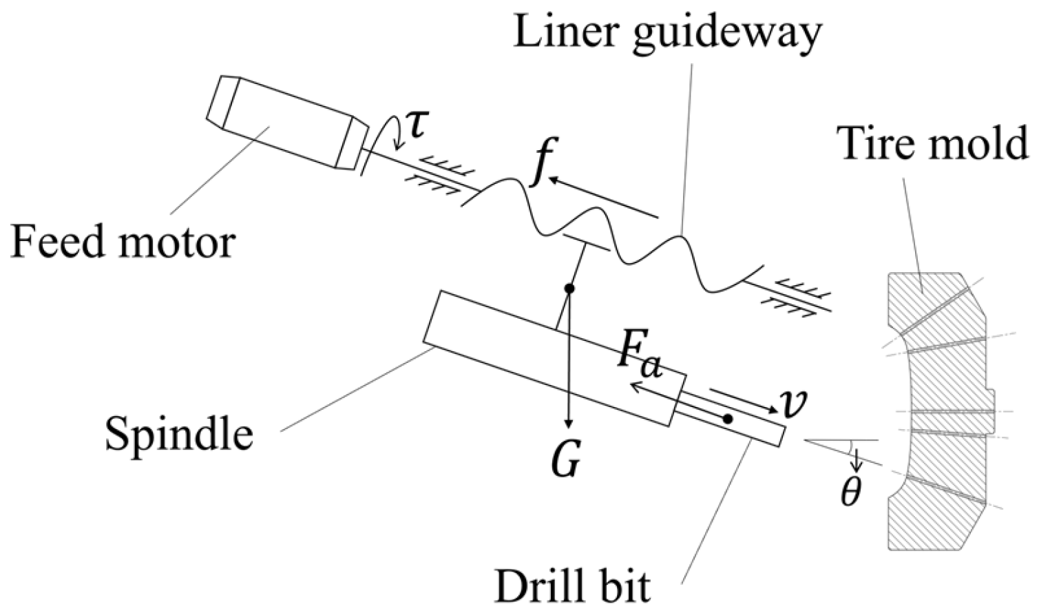
As shown in
Figure 9, when the end effector drills a vent hole at a drilling angle of
θ and a feed rate of
v, the feed torque can be expressed as follows:
where
denotes the mapping relationship among
,
,
and
. Here,
is the equivalent friction force in the linear feed system, including the friction between the slider and the guide rail, as well as the friction within the ball-screw assembly.
is the gravitational component along the feed direction,
is the drilling angle, and
is the axial force acting on the drill bit during drilling, which can be calculated as follows:
This equation consists of two components. The first component represents the empirical axial-force model for shallow-hole drilling [
35], where
is the axial-force coefficient determined by the workpiece material, drill geometry, and lubrication conditions;
is the drill diameter;
is the feed rate;
and
are empirical exponents; and
is a correction factor. The second component,
, represents the additional axial force acting on the drill during deep-hole drilling. This component is mainly influenced by chip-evacuation conditions. Because these factors cannot be fully measured or explicitly characterized,
is difficult to describe using a deterministic model.
3.2. GRU-Based Feed Torque Prediction Model (GFTM)
Because the drilling process is highly nonlinear and time-varying, it is difficult to establish an accurate mechanistic model. Therefore, this paper proposes a GRU-based feed-torque prediction model (GFTM). The proposed model exploits the ability of the GRU network to capture nonlinear temporal features and characterize the dynamic relationships among feed rate, drilling angle, and feed torque, thereby enabling prediction of the feed torque at the next time step. Compared with LSTM, GRU uses a simpler network structure, relying only on an update gate and a reset gate rather than the input, forget, and output gates and the separate memory cell used in LSTM. This reduces the number of trainable parameters and the computational complexity while maintaining the ability to capture temporal dependencies [
36]. Since the prediction model is embedded in the MPC controller and used for online optimization, GRU was selected to balance prediction accuracy, calculation speed, and real-time computational efficiency.
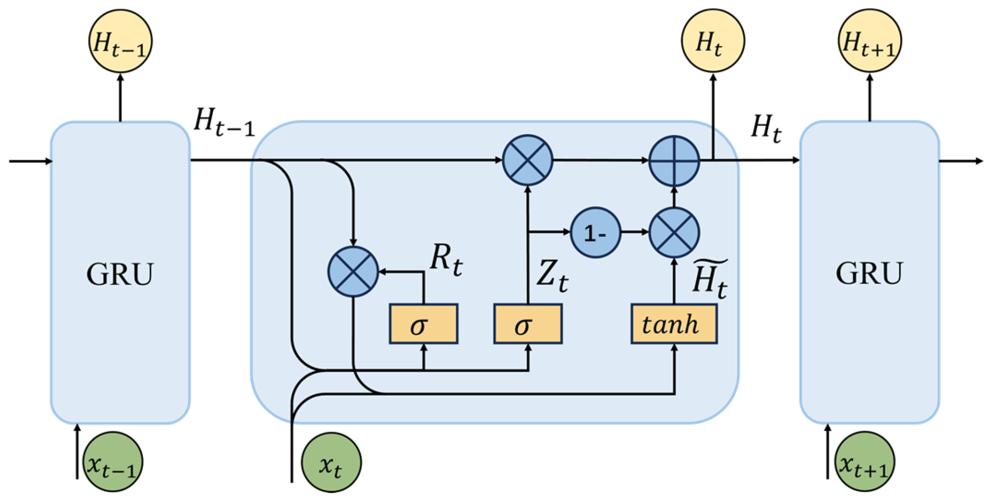
Figure 10 illustrates the architecture of the GRU network.
The internal working mechanism of the GRU can be described as follows. At time step
, given input
and the previous hidden state
, the reset gate
modulates the contribution of historical information by performing an element-wise operation on
, thereby controlling how much past information is used when computing the candidate hidden state. Subsequently, the update gate
determines the balance between preserving the previous hidden state
and adopting the new candidate information
. Specifically, the filtered historical component
, together with the current input
, is used to compute
. As a result, the current hidden state
is obtained by interpolating between
and
under the regulation of the update gate
. Through these gated operations, the GRU adaptively regulates information flow across control steps, enabling it to capture both short-term patterns and long-term dependencies. The corresponding update equations of the GRU unit are expressed as follows:
In these equations, denotes the sigmoid activation function applied to the reset gate and the update gate, while represents the hyperbolic tangent activation function. The term denotes the candidate hidden state, and is the hidden state output of the GRU unit at time step . The parameters , , , , , and the bias terms , , are trainable weight matrices and biases of the GRU network.
According to the analysis in
Section 3.1, the data-driven predictive relationship of the drilling system can be expressed as follows:
where
,
, and
, where
represents the length of input sequence. On this basis, the GFTM is constructed to predict the feed torque at the next time step,
.
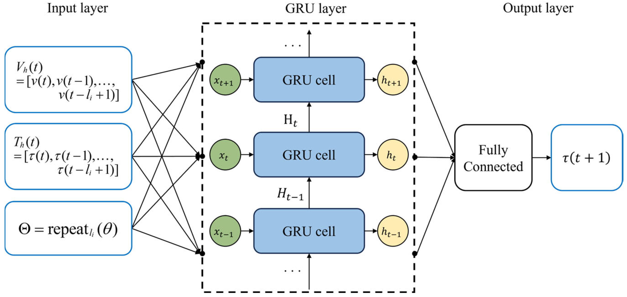
The architecture of the proposed model is illustrated in
Figure 11. This model consists of an input layer, a GRU layer, and an output layer. The input layer receives historical drilling data, including the feed rate sequence
, feed torque sequence
, and the corresponding drilling angle value
. The GRU layer is employed to extract temporal dynamic features from the input data. Finally, a fully connected layer is used as the output layer to map the features learned by the GRU layer to the feed torque
at the next time step.
During training, the mean squared error (MSE) is used as the loss function to quantify the discrepancy between the predicted and measured feed torque. The MSE provides a global indicator of prediction accuracy and imposes a heavier penalty on large deviations. The MSE loss is minimized through backpropagation to iteratively update the GRU parameters, thereby promoting stable convergence and reliable prediction. The loss function is defined in Equation (5).
To provide a comprehensive and objective assessment of the proposed GRU-based feed-torque predictor, the model performance is evaluated using multiple complementary metrics rather than a single criterion. Specifically, four widely used measures are adopted: mean absolute error (
MAE), root mean square error (
RMSE), mean absolute percentage error (
MAPE), and the coefficient of determination,
R2.
MAE,
RMSE, and
MAPE quantify the magnitude of prediction errors, with smaller values indicating higher prediction accuracy. In contrast,
R2 measures the goodness of fit between the predicted and measured torque values, with values closer to 1 indicating stronger agreement and greater explanatory capability. Together, these metrics enable a more rigorous evaluation of both the accuracy and reliability of the prediction model. The corresponding definitions are expressed as follows:
3.3. GFTMPC Flexible Drilling Controller
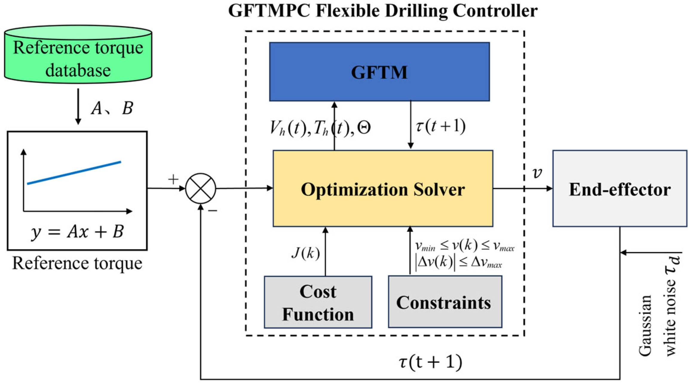
Based on the GFTM and MPC, a GFTMPC-based flexible drilling controller is developed, as shown in
Figure 12. The GFTM is embedded in the MPC framework as the prediction model, predicting future feed torque at each sampling instant. The predicted torque is then used in rolling-horizon optimization to determine the optimal feed rate under feed-rate and feed-rate-increment constraints.
Unlike a generic MPC implementation, the proposed controller is tailored to robotic small-diameter deep-hole drilling by coupling angle-aware feed-torque prediction, reference-torque trajectory tracking, and constrained feed-rate optimization. This formulation enables smooth online feed-rate regulation and suppresses abrupt torque and feed-rate fluctuations during drilling.
Specifically, the objective of GFTMPC is to determine the optimal feed rate through rolling-horizon optimization so that the system output tracks the reference trajectory
r(
t) as closely as possible. In this paper, given prediction and control horizons
and
, the optimization problem is formulated as the following cost function:
In the above formulation, a and b are weight parameters. The historical input and output are and , respectively. The reference output is defined as , while the predicted output over the prediction horizon is expressed by . The optimal feed rate sequence is expressed as and the corresponding feed rate increment sequence is . The feed rate is subject to upper and lower bounds and , and the control increment is constrained by . The first term of the cost function penalizes the deviation between the predicted feed torque and the reference torque over the prediction horizon , thereby enhancing tracking performance. The second term penalizes excessive variations in the control input over the control horizon , thereby promoting smooth feed-rate regulation. From a physical perspective, these two terms correspond to minimizing the deviation between the end-effector feed torque and the reference torque, and minimizing variations in the feed rate during drilling to reduce adverse effects on the drill bit.
Since the torque prediction value
in Equation (10) is obtained via a deep learning model, the nonlinear mapping function
cannot be directly solved, which makes
difficult to solve. To address this issue, the adaptive gradient descent combined with numerical differentiation [
37] is employed to solve the optimization problem and handle the associated constraints. Therefore, the following formula can be obtained:
In the formula,
represents the learning rate and
is the number of iterations. Therefore, the objective function
and
can be rewritten as:
Constraints can be handled using the projected gradient method. Since the constraints involved in the formulated optimization problem are linear constraints, Equations (11) and (12) can be reformulated as follows:
where
and
are projection functions of the vector
and
, respectively. They can be defined as follows
By solving the optimization problem, the optimal feed rate sequence can be obtained. Then, the first element of is used as the control signal in the system to ensure that the system output can accurately track the reference feed torque.
4. Simulation and Experimental Validation
4.1. Data Collection and Analysis
4.1.1. Data Collection
Based on the developed robotic drilling system, data were collected during the acceleration and steady stages of the staged drilling process described in
Section 3.1.1.
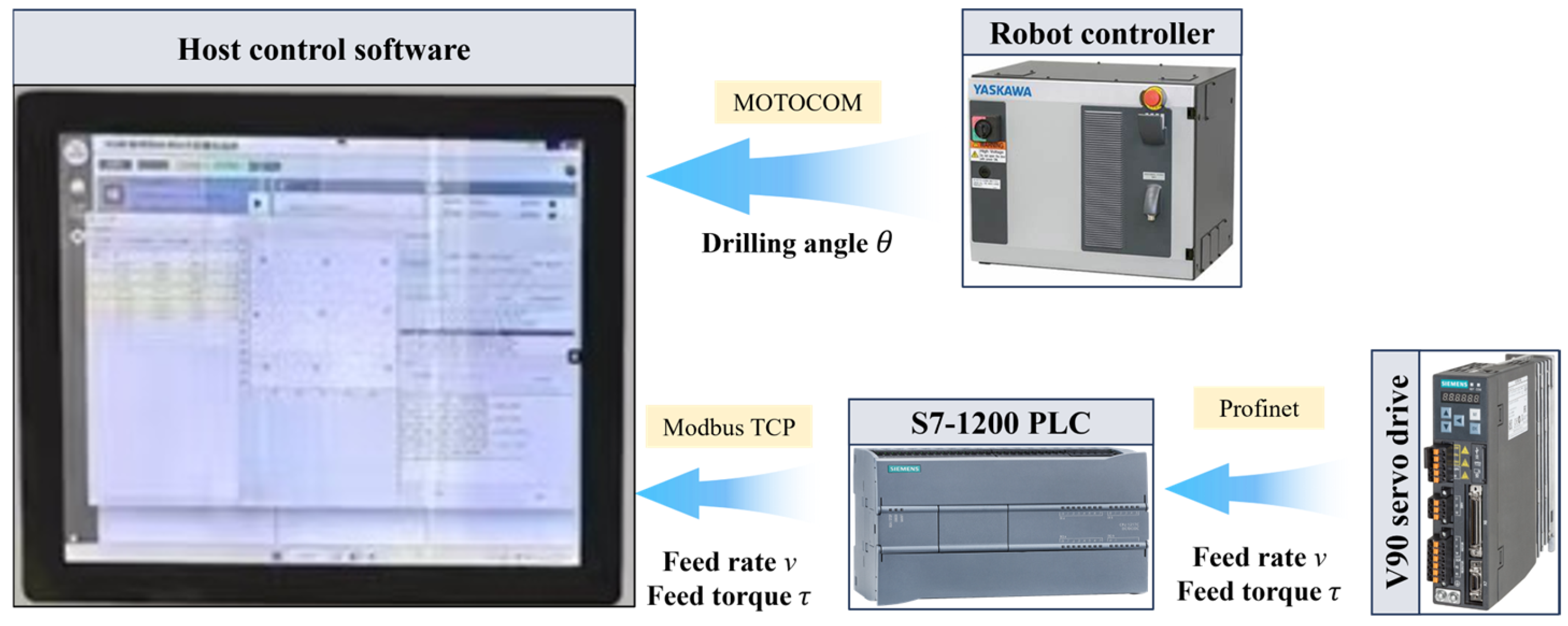
As shown in
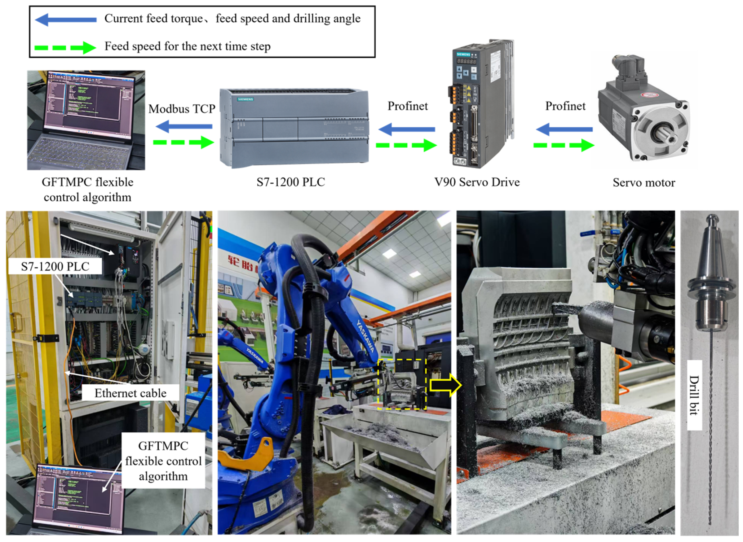
Figure 13, the data-acquisition system consists of host control software, a robot controller, an S7-1200 PLC (Siemens AG, Munich, Germany), and a SINAMICS V90 servo drive (Siemens AG, Munich, Germany). For each drilling process, once drilling begins, the host control software acquires the current drilling angle from the robot control cabinet via the MotoCom interface. When the drilling process enters the acceleration stage, the system starts collecting the feed rate and feed torque and continues recording these data until the drilling operation is completed. Because data from the Siemens V90 servo drive cannot be accessed directly by the host control software, an S7-1200 PLC is used as an intermediate node. The PLC acquires the feed rate and feed torque from the servo drive in real time through the Profinet protocol and then transmits the data to the host control software through Modbus TCP. This process is repeated throughout multi-hole drilling, thereby enabling continuous acquisition and centralized storage of drilling data from multiple holes.
The sampling period was set to 0.3 s, and drilling data were collected from 459 holes drilled at different angles. For each hole, the dataset included a feed-rate sequence, a feed-torque sequence, and the corresponding drilling angle. The detailed data structure is presented in
Table 3.
4.1.2. Data Analysis
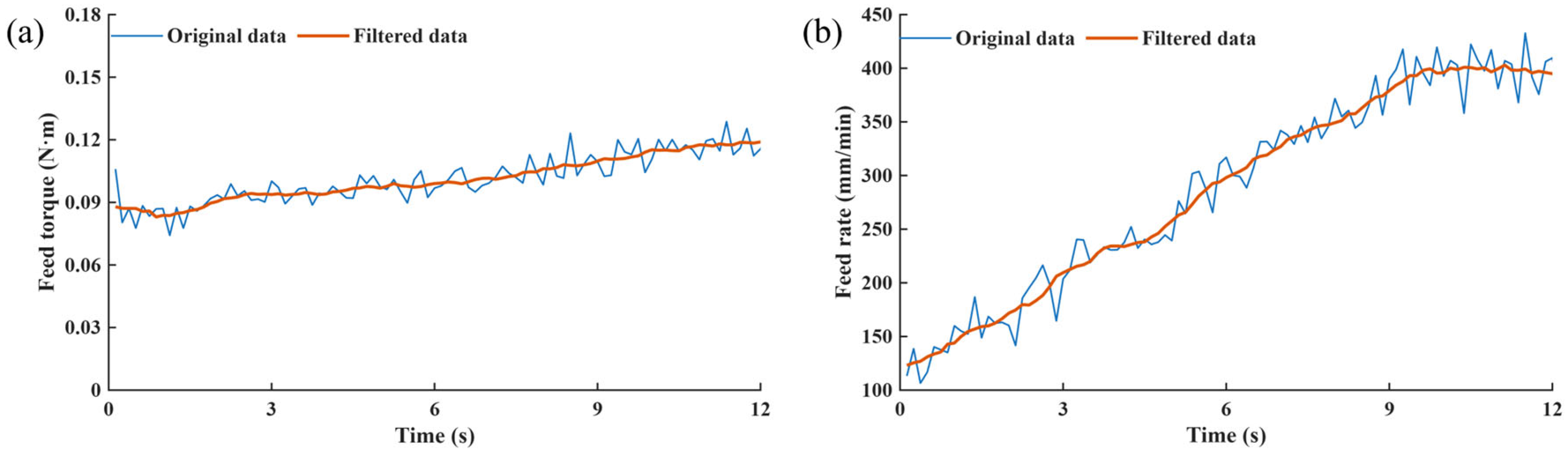
To improve data quality, suppress noise, and better capture the key temporal characteristics of the drilling process, a moving-average filter with a window size of 10 was applied to preprocess the feed-rate and feed torque signals, as shown in
Figure 14.
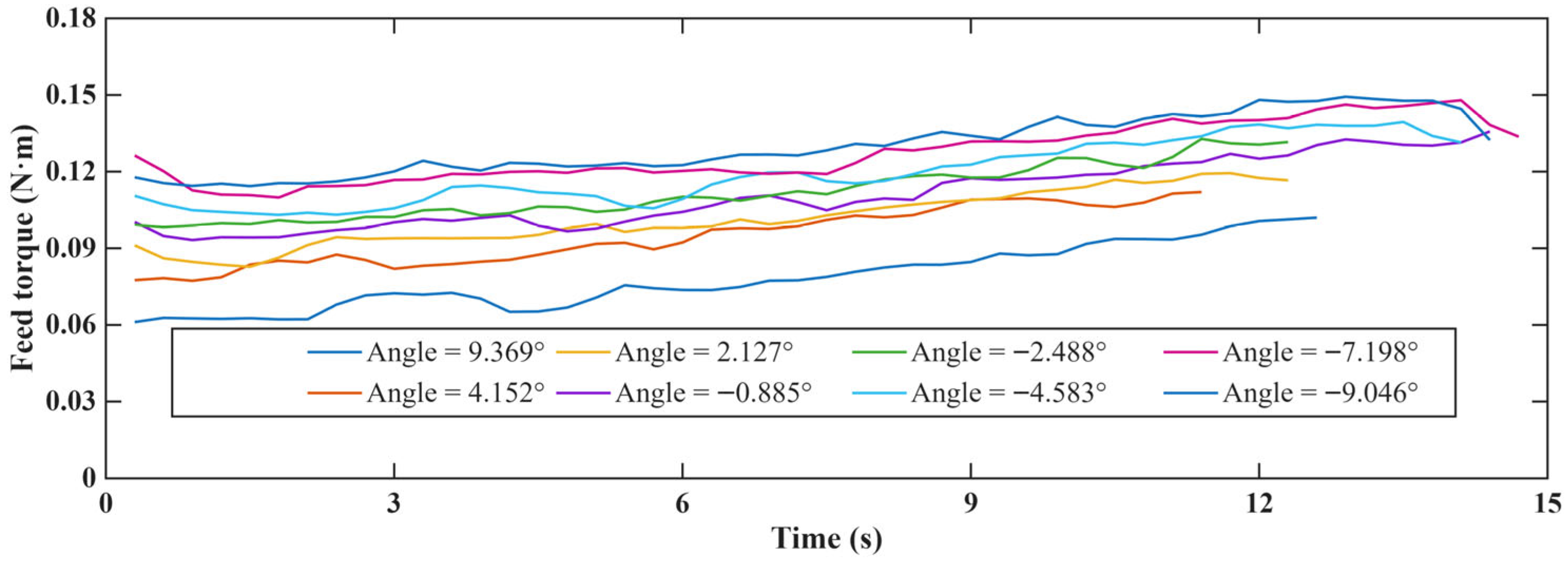
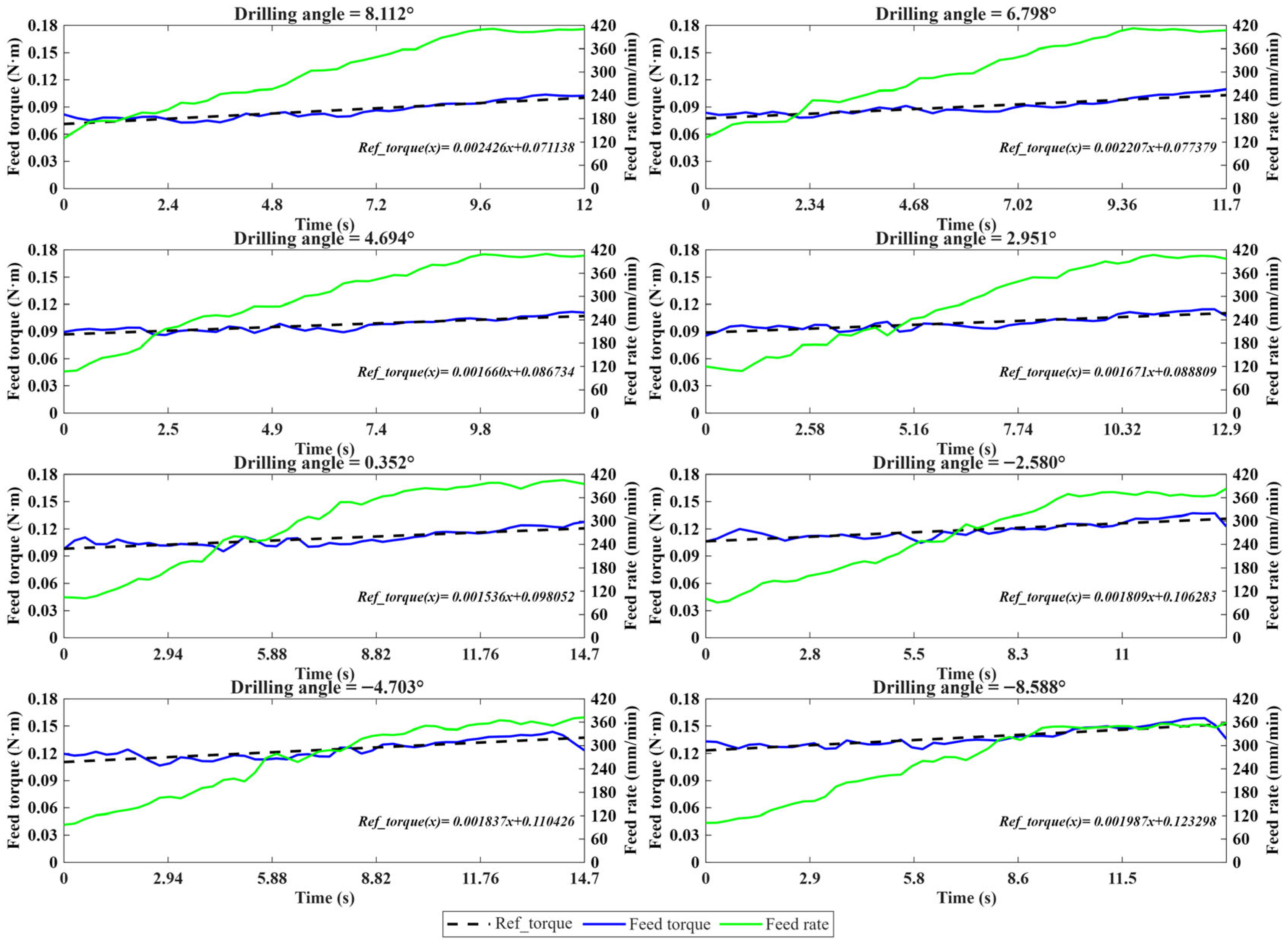
Because feed torque is strongly correlated with the drilling angle, a comparative analysis was further conducted to examine the variation in feed torque during the acceleration and steady stages of the staged drilling process under different drilling-angle conditions.
As shown in
Figure 15, the feed torque generally increases gradually over time under different drilling angles. Meanwhile, the drilling angle has a significant influence on the feed-torque level: as the drilling angle decreases, the magnitude of the feed torque increases progressively. This trend can be mainly attributed to the fact that, during upward inclined drilling, the feed motor is affected by spindle gravity and other factors and therefore must bear a greater load and overcome higher resistance, resulting in a higher feed-torque level. These results are consistent with the actual load characteristics and basic physical principles.
Because variations in drilling angle significantly affect the feed-torque level, it is difficult to adopt a unified reference trajectory for all drilling angles. Within the MPC framework, the reference trajectory does not need to be an exact physical model of feed-torque evolution; rather, it serves as the desired control target for the predicted output. Therefore, its form can be designed according to the specific control objective. In small-diameter deep-hole drilling, a stable and gradually increasing feed-torque target is preferred in order to avoid abrupt torque changes and excessive feed-rate fluctuations. To address this issue, a reference-torque database was constructed from acceleration-stage and steady-stage data collected in
Section 4.1, thereby providing targeted reference-torque profiles for drilling processes under different drilling angles.
The reference torque database was constructed as follows. First, feed-torque data were extracted from the 459 collected datasets. Next, the linear parametric equation (
y = At + B) was fitted using the least-squares method, and the corresponding coefficients
A and
B were identified. Finally, these coefficients were used to establish an empirical reference torque database. Representative empirical reference-torque parameters are listed in
Table 4.
4.2. Simulation Validation of GFTMPC
4.2.1. GFTM Training and Evaluation
- (1)
Dataset construction: Based on the filtered data described in
Section 4.1, Z-score normalization was applied to eliminate scale differences among the features. The data were then randomly divided on a per-hole basis into training, validation, and test sets at ratios of 70%, 20%, and 10%, respectively. Finally, a sliding-window method was used to construct the training samples, resulting in 13,154 training samples, 3686 validation samples, and 1930 test samples.
- (2)
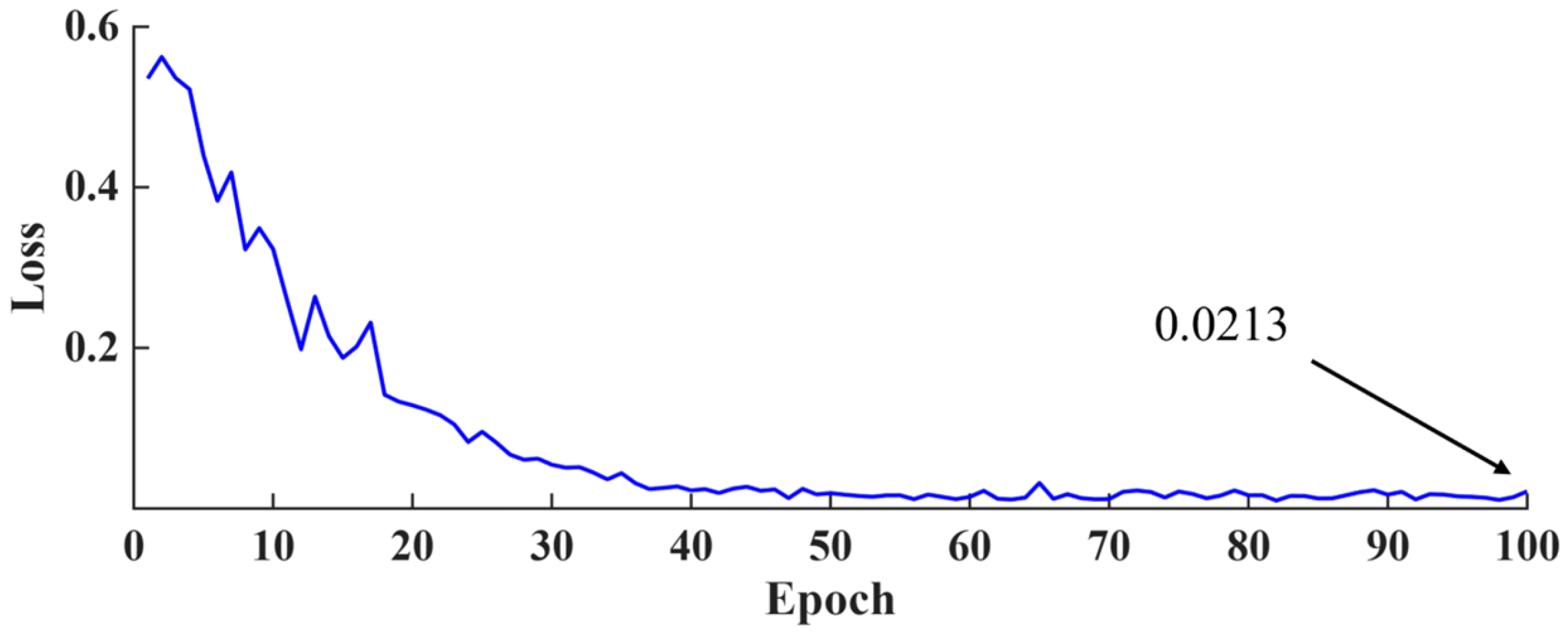
Hyperparameter configuration and training: The Adam algorithm was employed to optimize the GRU model parameters during training. The hyperparameters were set as follows: the input-sequence length was set to 2 in order to balance prediction accuracy and online computational efficiency, and the output-sequence length was set to 1; the network contained 128 hidden nodes; the learning rate was set to 1 × 10
−4; the batch size was 128; and the model was trained for a maximum of 100 epochs. As shown in
Figure 16, the training loss converged to 0.0213 within 100 epochs, indicating that the network reached a stable convergence state.
- (3)
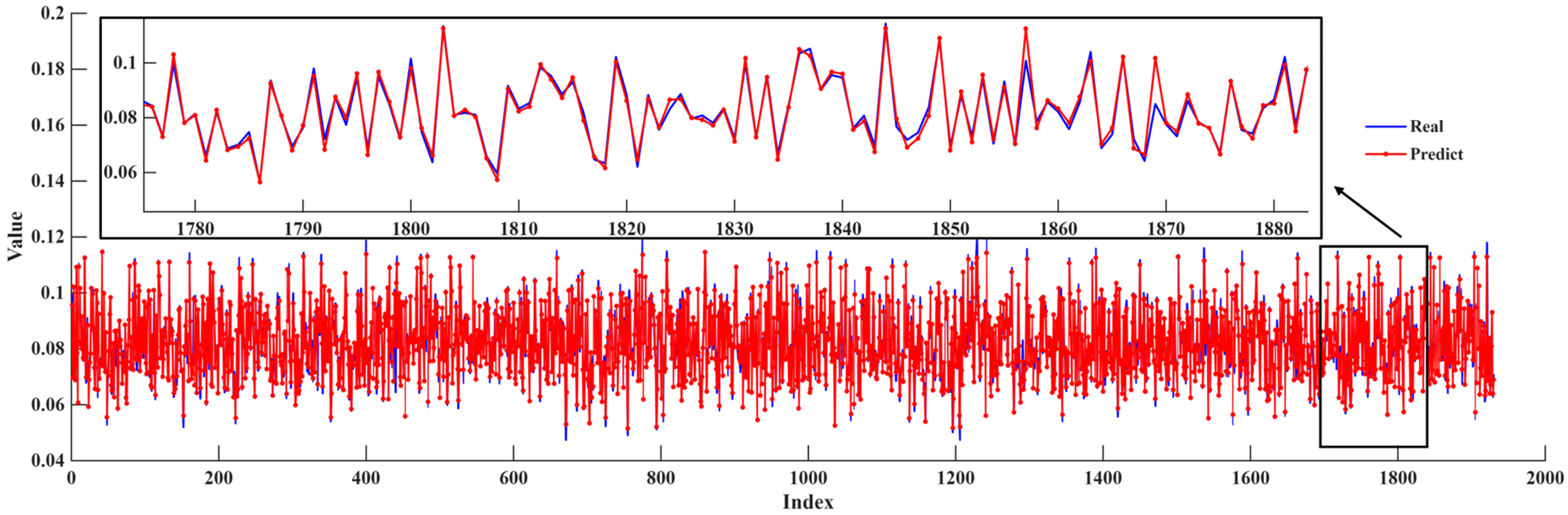
Model evaluation: Because the predictive model constitutes the core component of MPC, its accuracy is critically important. To evaluate its predictive performance, the trained GFTM was tested on the test dataset. The prediction results are shown in
Figure 17, and the corresponding evaluation metrics are summarized in
Table 5.
The GFTM achieves an R2 value of 0.9682, indicating excellent agreement between the predicted and measured feed torque. Moreover, the MAE and RMSE are as low as 0.0016 and 0.0022, respectively, while the MAPE is only 1.9914%. These results demonstrate that the proposed model exhibits high prediction accuracy and reliability.
Collectively, these evaluation results confirm that the GFTM can effectively capture the dynamic relationships among drilling angle, feed rate, and feed torque. In addition to its high prediction accuracy, the model also demonstrates adequate predictive performance under the tested conditions, thereby fully meeting the requirements for subsequent MPC implementation.
4.2.2. GFTMPC Flexible Control Simulations
- (1)
PID baseline controller: To provide a baseline for comparison, a constrained PID-controlled staged drilling method was introduced. PID control was selected as a representative conventional feedback-control method because of its simple structure, widespread use in drilling applications, and ease of implementation. The PID controller adjusts the feed rate according to the feed-torque tracking error, which is defined as follows
where
is the reference feed torque and
is the simulated feed torque at the
-th control step. The PID correction term is calculated as follows
where
,
, and
are the proportional, integral, and derivative gains, respectively. To reduce integral windup under saturation, the integral term is updated as follows
where
is the anti-windup coefficient,
is the unconstrained feed-rate command, and
is the constrained feed-rate command. The derivative term is filtered as follows
where
is the derivative filtering coefficient. The feed-rate command is obtained by adding the PID correction to the nominal staged-feed profile:
where
is the nominal staged-feed rate.
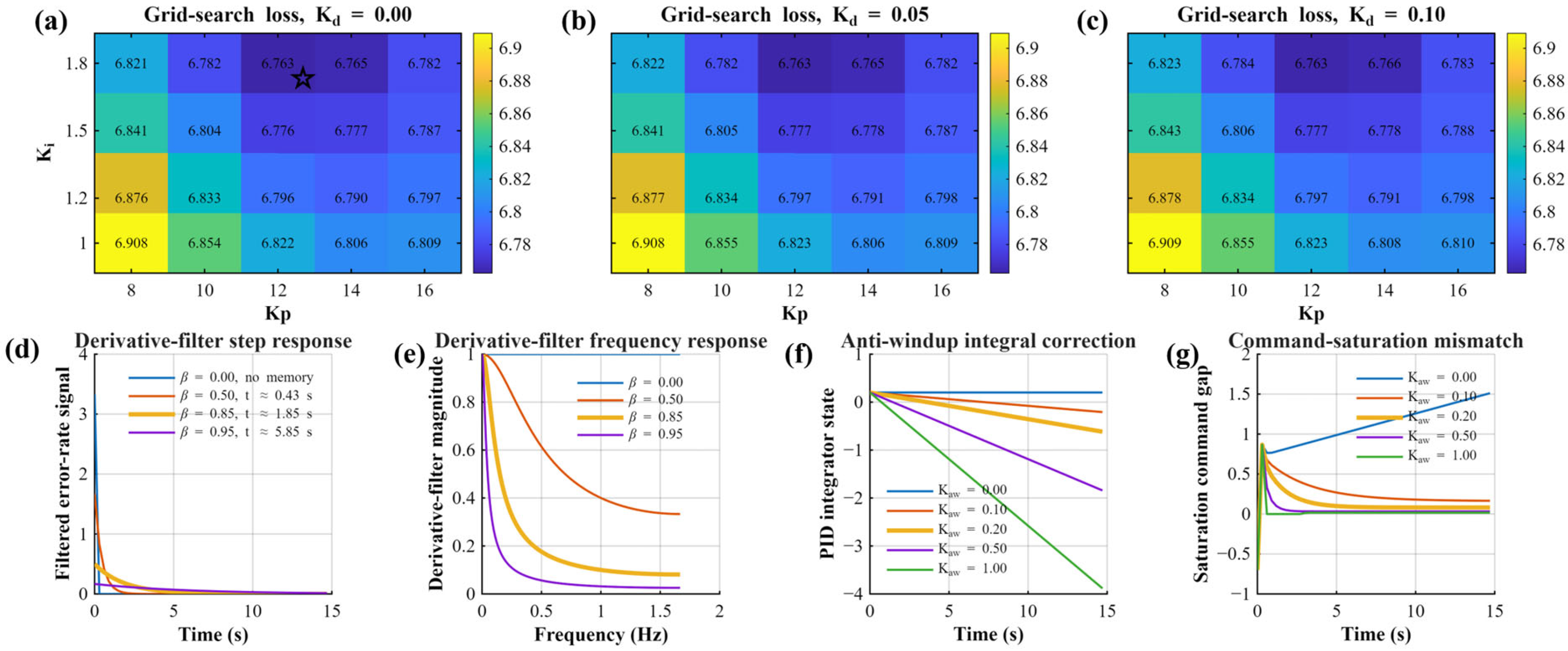
In the simulation, a single fixed gain set was used for all drilling angles and disturbance conditions. The PID parameters were determined through grid search using representative normal and disturbed cases, and the final values were set as
Kp = 12,
Ki = 1.8,
Kd = 0, β = 0.85, and
Kaw = 0.20. Details are provided in
Appendix A.1.
- (2)
Simulation settings: During the simulation, the trained GFTM was used as the simulated end-effector model for both GFTMPC and the PID baseline controller. Gaussian white noise with zero mean and a standard deviation of 0.001 was added to the model output to simulate noise in signal transmission and measurement. Meanwhile, an external disturbance term was added to the system output to simulate sudden changes in feed torque during the drilling process.
The GFTMPC and PID used the same initial drilling data, drilling angles, reference torque trajectories, disturbance amplitudes, disturbance occurrence times, feed-rate constraints, feed-rate-increment constraints, sampling period, and simulation duration. Specifically, the feed-rate constraints were defined as
mm/min and
mm/min, and the maximum feed-rate increment was limited to
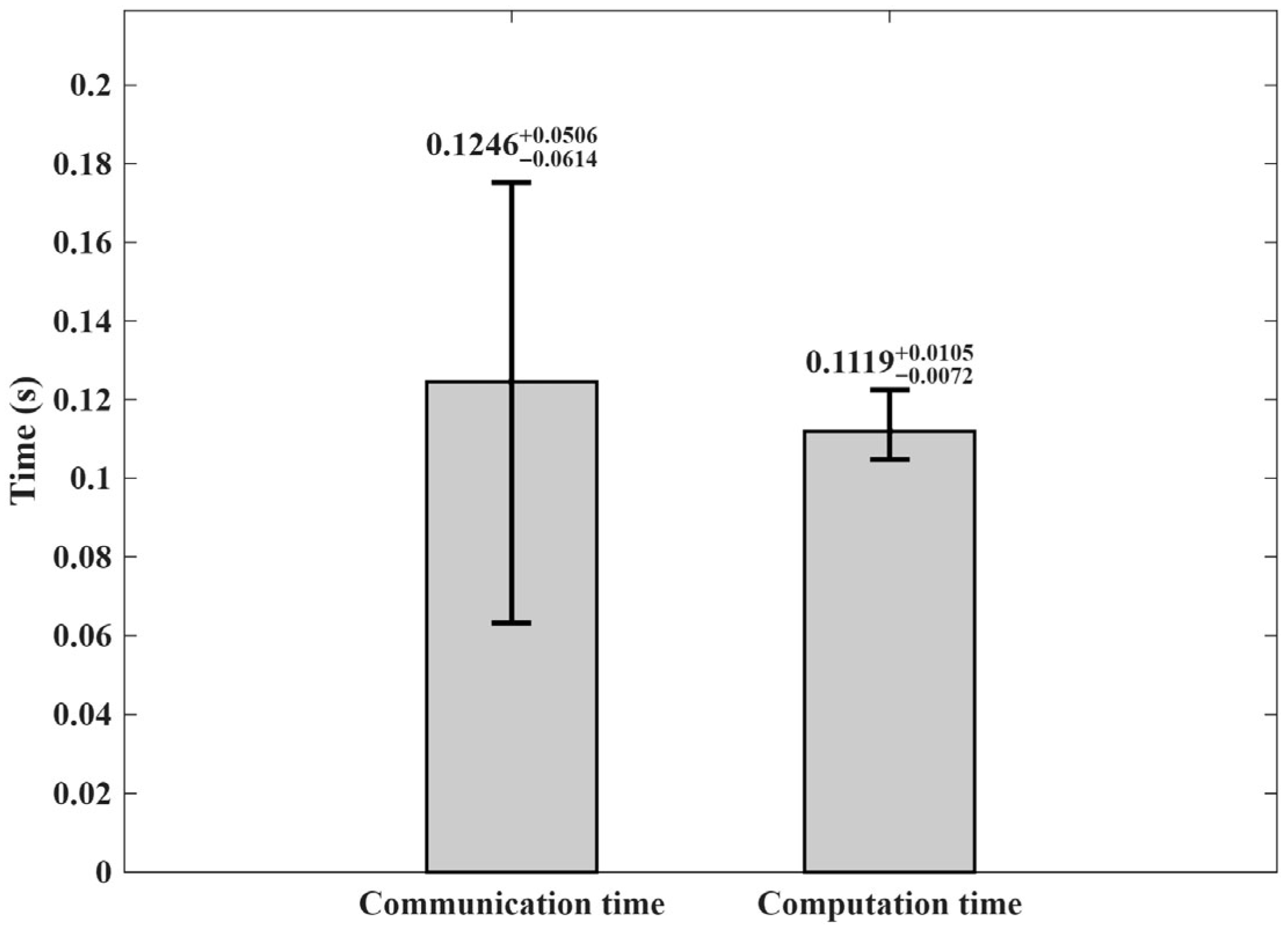
mm/min. The control period was set to 0.3 s based on the time-consumption analysis in
Appendix A.3, and each simulation was conducted over 50 time steps, corresponding to a total duration of 15 s.
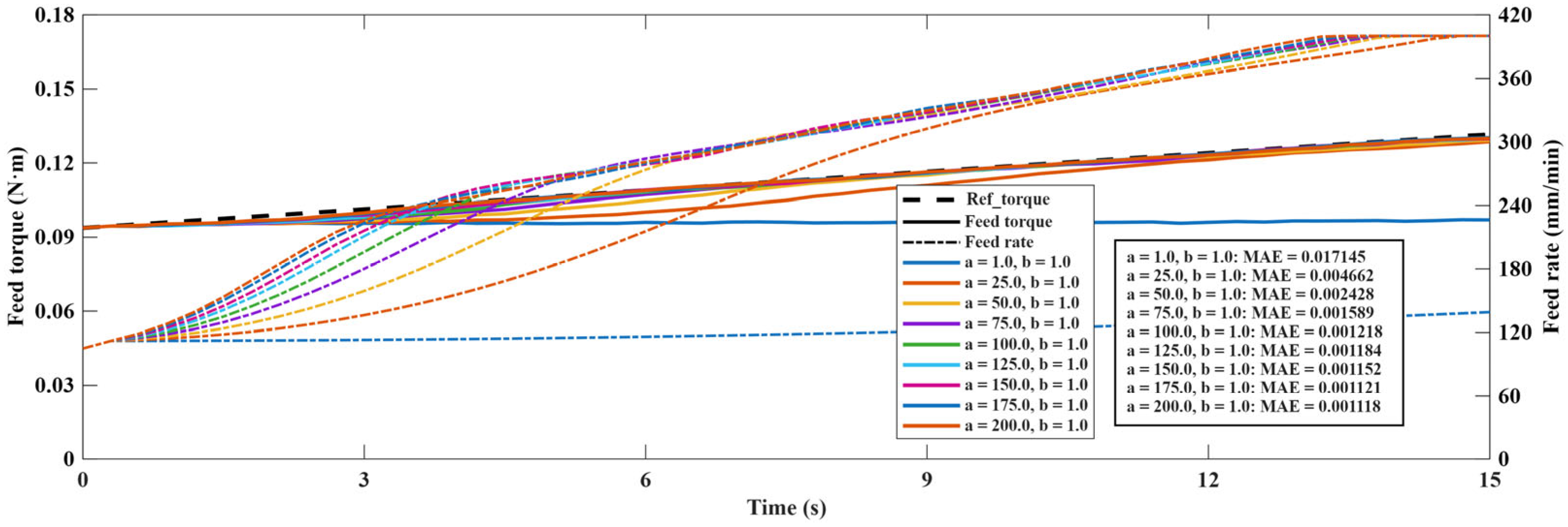
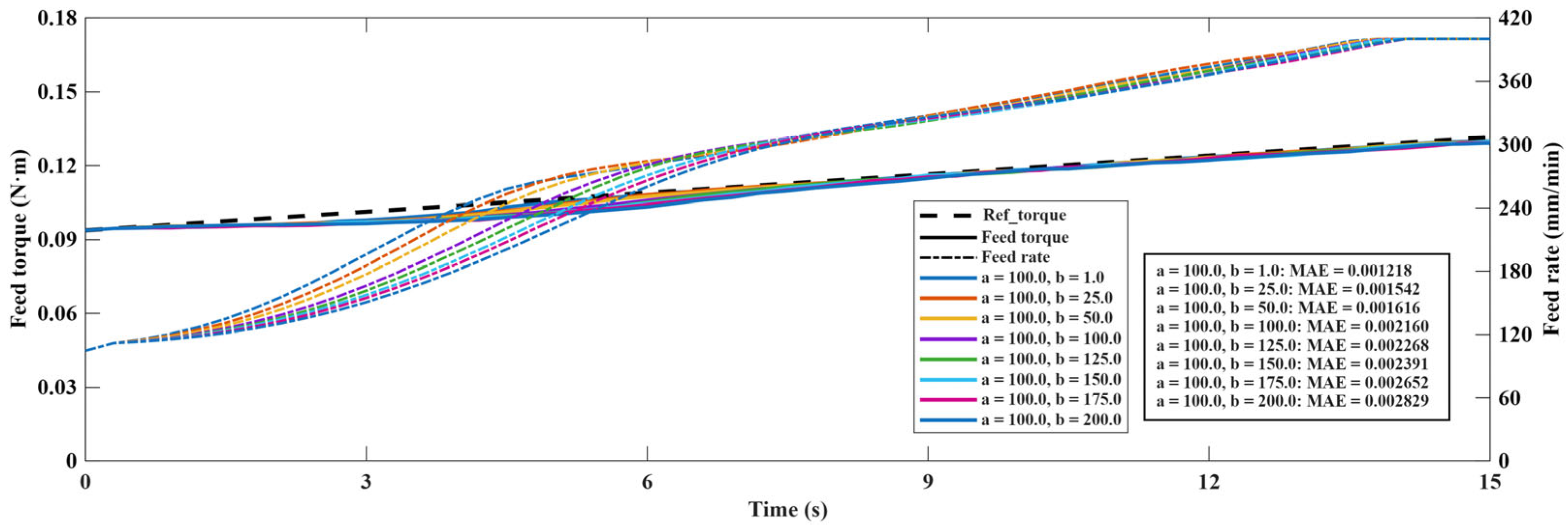
For GFTMPC, the GFTM was embedded into the MPC framework to predict future feed torque and optimize the feed-rate sequence under constraints. The weight parameters were selected based on the sensitivity analysis in
Appendix A.2, with
a = 100 and
b = 1. The prediction horizon and control horizon were set to
and
, respectively.
The disturbance levels of feed torque are listed in
Table 6. Owing to the effects of spindle gravity, linear-guideway friction, and other angle-dependent factors, the feed-torque range varies with drilling angle. Therefore, it is difficult to describe the disturbance level using a fixed absolute value. In this study, the disturbance level was classified as normal, slight disturbance, or severe disturbance relative to the reference torque amplitude corresponding to each drilling angle.
Four simulation conditions were considered: normal drilling under different drilling angles, drilling under different disturbance amplitudes, drilling with disturbances applied at different time instants, and composite conditions combining different drilling angles and disturbance amplitudes. The specific parameters for each condition are listed in
Table 7.
- (3)
Simulation scheme and result analysis.
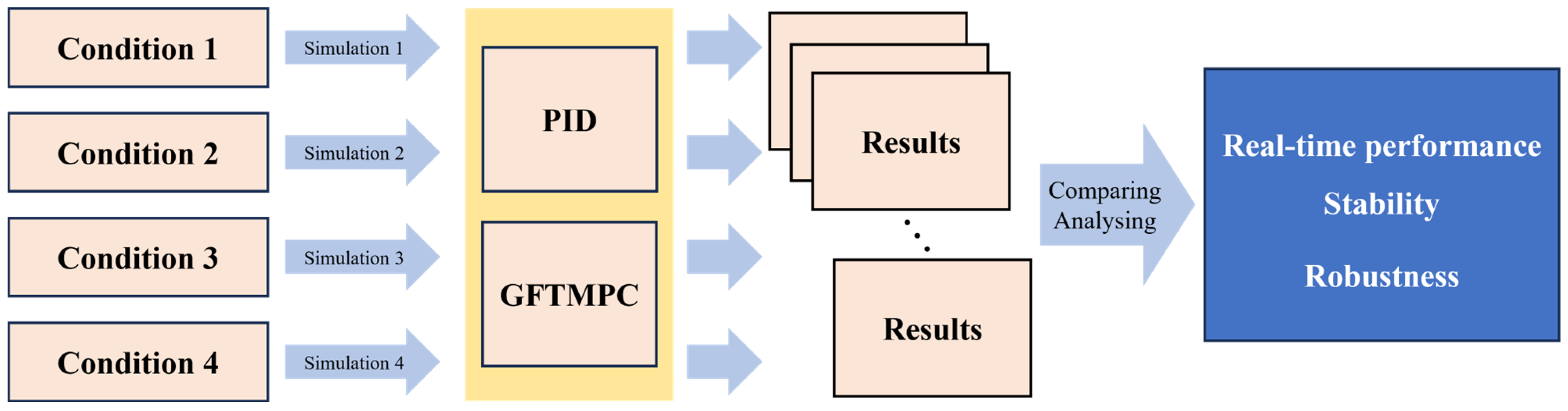
Figure 18 illustrates the simulation scheme used to evaluate the PID baseline and the proposed GFTMPC method. Independent simulations were conducted under each of the four simulation conditions described above. The corresponding results were then compared and analyzed in order to assess the real-time performance, stability, and robustness of the GFTMPC controller.
To quantitatively evaluate the control performance, three metrics were calculated, as summarized in
Table 8. The maximum torque deviation was used to evaluate the suppression of peak torque deviation during the drilling process. The
RMSE of feed-rate increment was used to evaluate the smoothness of feed-rate regulation. The saturation ratio of feed-rate increment represented the proportion of control steps in which the feed-rate increment reached its imposed constraint. In
Table 8, Imp. denotes the improvement per-centage of GFTMPC relative to PID. The results are compared and analyzed together with the simulation curves.
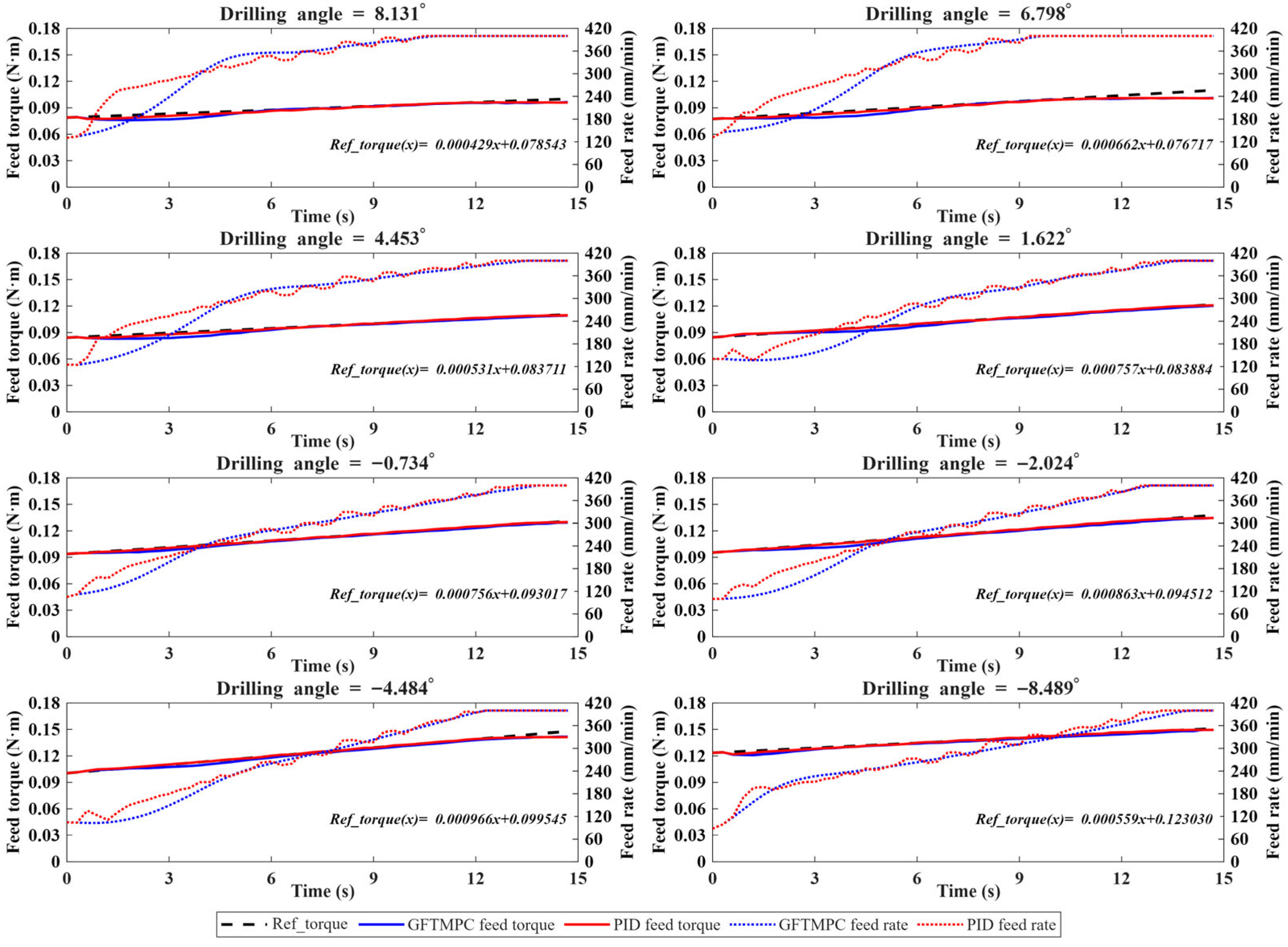
As shown in
Figure 19, under normal drilling conditions with different drilling angles, both PID and GFTMPC can track the reference torque trajectory. In terms of maximum torque deviation, PID achieves a smaller value than GFTMPC under normal conditions. However, the feed-rate regulation of GFTMPC is smoother. Specifically, the RMSE of feed-rate increment decreases from 11.6792 mm/min for PID to 7.5328 mm/min for GFTMPC, corresponding to a reduction of 35.50%. In addition, the saturation ratio of feed-rate increment is reduced from 0.005 to 0, indicating that GFTMPC avoids feed-rate-increment constraint activation during normal drilling. These results show that GFTMPC produces smoother feed-rate commands and more stable control actions under normal operating conditions.
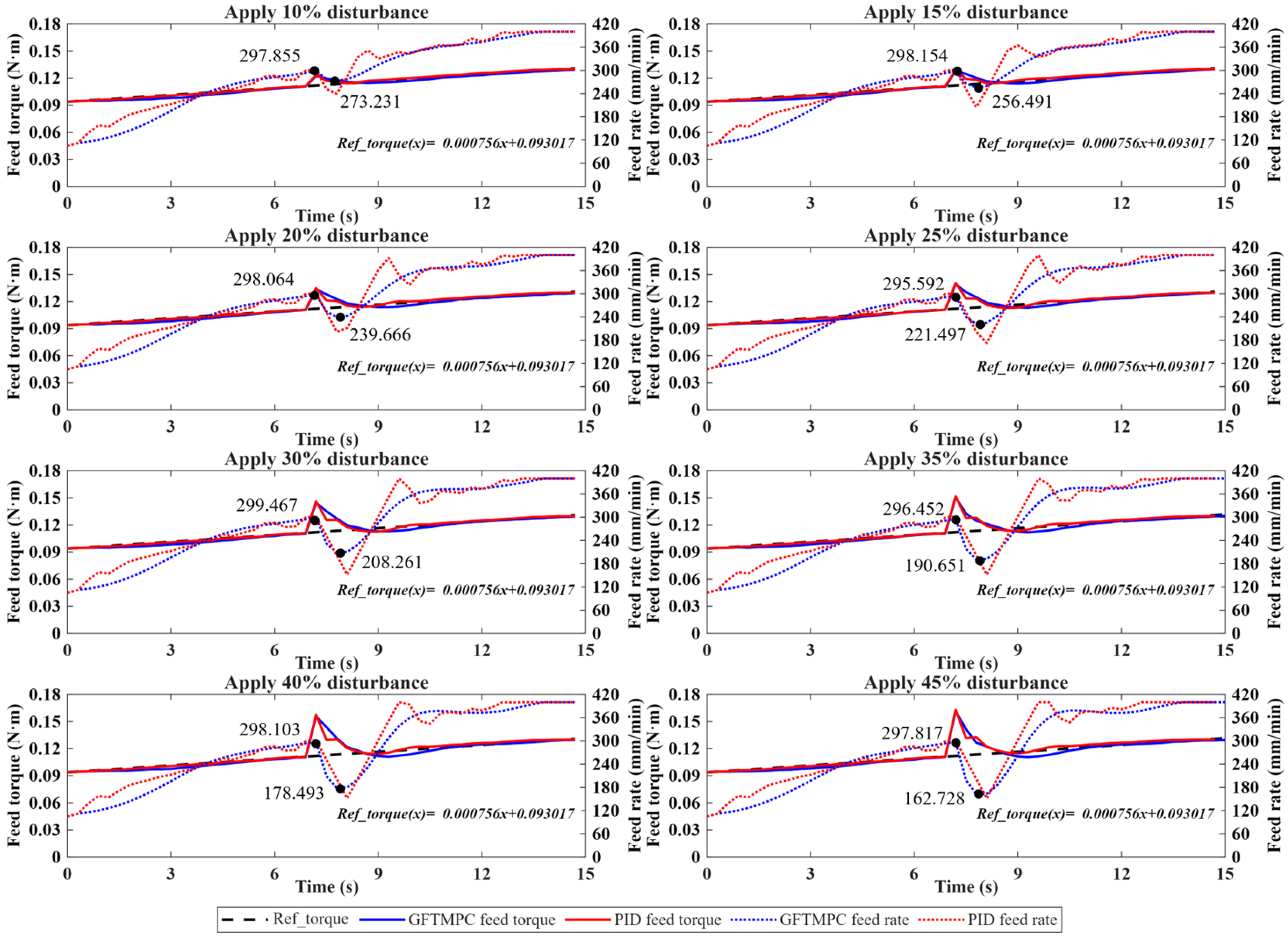
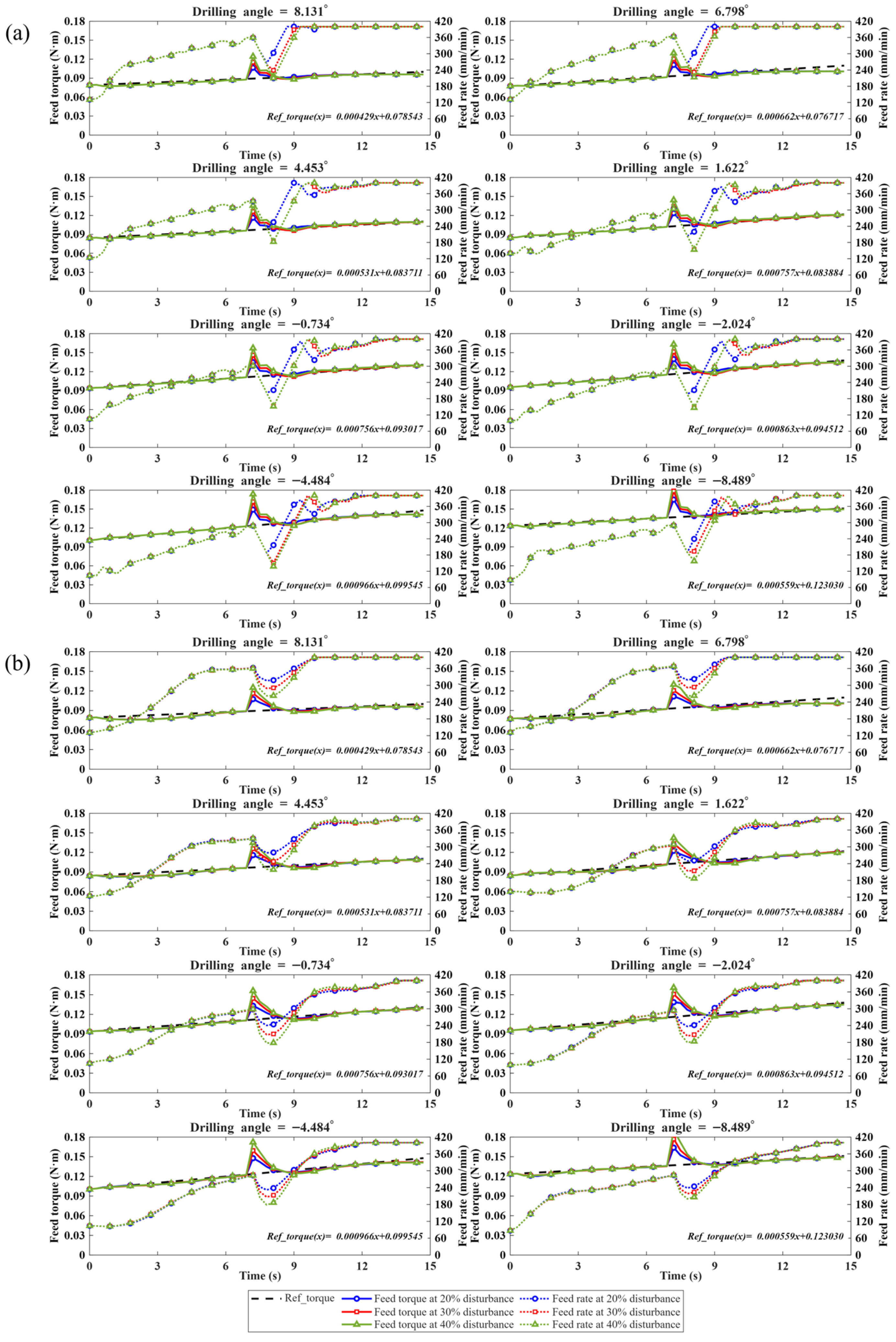
As shown in
Figure 20, when disturbances with different amplitudes are introduced, GFTMPC exhibits better peak-torque suppression, smoother feed-rate regulation, and fewer feed-rate-increment constraint activations than PID. Specifically, the average maximum torque deviation decreases from 0.0314 to 0.0301, corresponding to an improvement of 4.16%. Meanwhile, the RMSE of feed-rate increment decreases from 21.2934 mm/min to 14.1220 mm/min, and the saturation ratio of feed-rate increment decreases from 0.1125 to 0.0125. After disturbances occurred, the controller adaptively reduced the feed rate as the disturbance magnitude increased, with the maximum reduction rising from 24.624 to 135.089 mm/min. The feed torque returned to the vicinity of the reference trajectory within 2 s, indicating effective disturbance suppression and smooth control behavior.
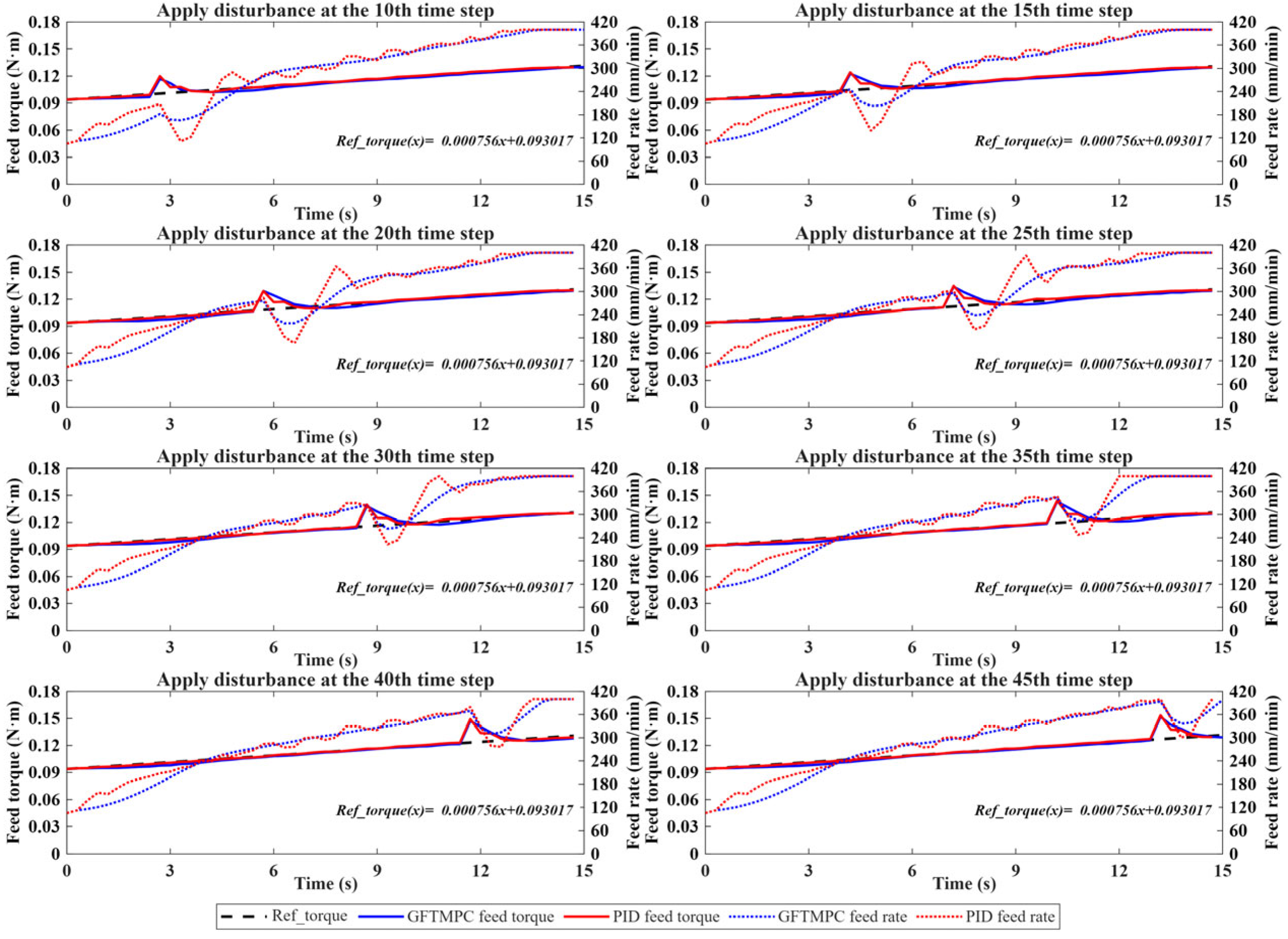
As shown in
Figure 21, when disturbances are introduced at different time instants, the response characteristics of GFTMPC remain generally consistent, indicating low sensitivity to disturbance timing. Compared with PID, GFTMPC reduces the maximum torque deviation from 0.0230 to 0.0215, corresponding to an improvement of 6.69%. Meanwhile, the RMSE of feed-rate increment decreases from 19.3718 mm/min to 10.6339 mm/min, and the saturation ratio of feed-rate increment decreases from 0.0900 to 0. In all cases, the feed torque returns to a stable state within 2 s without sustained oscillation or obvious instability. These results indicate that the proposed GFTMPC method can maintain smoother feed-rate regulation, avoid feed-rate-increment constraint activation, and exhibit strong temporal robustness under disturbances occurring at different time instants.
Figure 22 further compares PID and GFTMPC under composite conditions involving different drilling angles and disturbance amplitudes, which more closely represent practical robotic drilling conditions. Under these conditions, the feed-torque response is affected simultaneously by angle-dependent drilling dynamics and sudden torque disturbances. The results show that GFTMPC reduces the average maximum torque deviation from 0.0329 to 0.0320, corresponding to an improvement of 2.70%. Meanwhile, the RMSE of feed-rate increment decreases from 21.4844 mm/min to 14.1275 mm/min, and the saturation ratio of feed-rate increment decreases from 0.1217 to 0.0133. Although the peak deviation and recovery process vary with drilling angle, the overall response trend remains consistent, and the feed torque can be restored to the normal range within approximately 3 s through real-time feed-rate regulation.
Overall, across all 48 simulation cases for the two methods, GFTMPC reduces the overall RMSE of feed-rate increment by 34.82% and the saturation ratio of feed-rate increment by 90.78% compared with PID. These results indicate that the main advantage of GFTMPC lies in smoother feed-rate regulation, better constrained control behavior, and fewer abrupt feed-rate-increment constraint activations under varying drilling angles and disturbance conditions. These characteristics are particularly important for small-diameter deep-hole drilling, where sudden feed-rate changes may aggravate torque fluctuation, unstable chip evacuation, tool deflection, and drill-bit breakage. Therefore, the simulation results demonstrate that the proposed GFTMPC method provides a stable and robust feed-regulation strategy for robotic small-diameter deep-hole drilling, thereby establishing a solid control basis for subsequent drilling experiments and engineering applications.
4.3. Experimental Validation in Industrial Drilling
To validate the effectiveness of the GFTMPC-based flexible drilling control method in practical small-diameter deep-hole drilling, experiments were conducted using the proposed robotic drilling system, as shown in
Figure 23.
- (1)
Experimental setup: The devices used are listed in
Table 1. A Φ1.8 × 130 mm parabolic deep-hole drill bit was used. The proposed GFTMPC-based flexible drilling control algorithm was implemented on a laptop computer, which communicated with the PLC via Modbus TCP to achieve real-time closed-loop control of the drilling process. During the experiments, the feed rate and feed torque required by the prediction model were obtained from the servo drives, whereas the drilling angle was acquired from the robot controller. Using these inputs, the optimal feed rate for the next control step was calculated online, thereby enabling flexible regulation of the drilling process. The prediction model and control parameters used in the experiments were the same as those adopted in the simulation studies.
- (2)
Experimental results and analysis.
Based on the above experimental setup, drilling experiments were conducted on three tire-mold tread blocks, involving a total of 1038 holes with an average depth of 73.6 mm. No tool breakage occurred during the experiments. The actual drilling results are summarized in
Table 9. In terms of drilling conditions, holes drilled under normal and slight disturbance conditions accounted for a combined 94.9%, indicating that most drilling processes remained stable or were affected only by minor disturbances. In contrast, holes drilled under severe-disturbance conditions accounted for 5.1%, suggesting that strong disturbances occurred relatively infrequently during the actual drilling process.
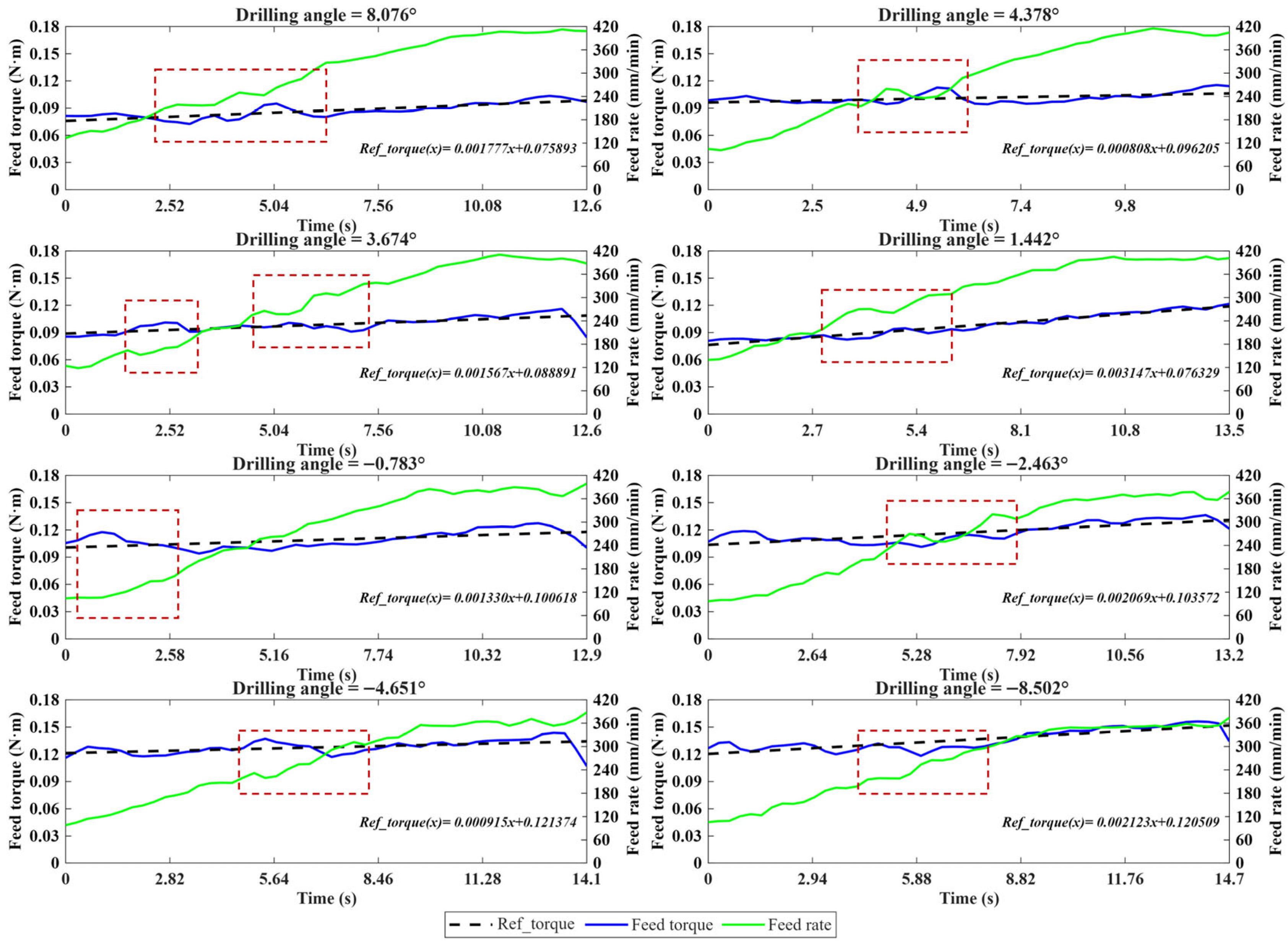
Normal drilling data at different drilling angles are shown in
Figure 24. Under normal conditions, the system output torque at all drilling angles tracks the reference torque well, with only small fluctuations and without obvious abrupt changes or sustained deviations, indicating that the proposed control method exhibits stable control performance. As the drilling process proceeds, the feed rate varies smoothly under the action of the controller and can be adaptively adjusted according to different drilling angles.
Figure 25 presents the experimental drilling results under slight-disturbance conditions. Compared with the normal condition, the feed torque exhibits slight deviations and fluctuations under certain disturbed conditions; however, the overall variation remains within a controllable range and does not induce sustained oscillations. Correspondingly, the feed rate can be adjusted in a timely manner to suppress further deviation of the torque from the reference trajectory, and the actual torque can return to the vicinity of the reference value within a short time. These results indicate that the proposed method exhibits strong real-time capability, stability, and robustness under slight disturbances.
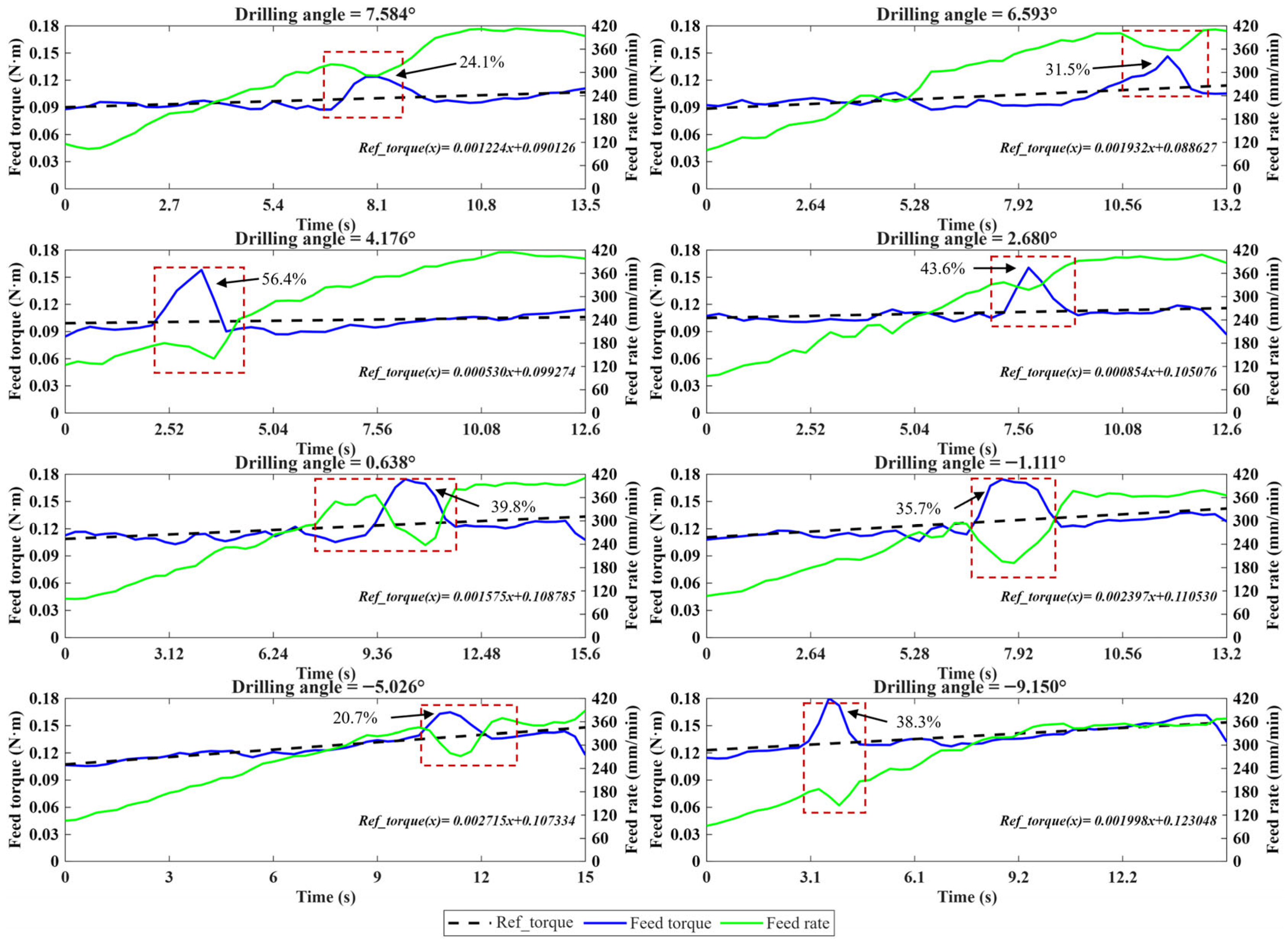
The drilling experimental results under severe disturbance conditions exhibit more pronounced dynamic characteristics. As shown in
Figure 26, the feed-torque curves at different drilling angles display substantial fluctuations, with variation ranges from 20.7% to 56.4%; in some cases, sharp peak responses or transient oscillations can also be observed. These results indicate that strong disturbances have a significant effect on drilling-process stability.
Nevertheless, once a disturbance occurs, the controller is able to respond in a timely manner and perform active regulation, thereby demonstrating satisfactory real-time performance. Moreover, after a brief transient response, the feed torque can return to the vicinity of the reference trajectory within 3 s, without sustained instability or loss of control. This indicates that the overall system remains controllable and retains satisfactory real-time performance.
Compared with the simulation results, the recovery process observed in the experiments is relatively slower, and the fluctuation patterns are more complex. This can be attributed to the fact that, in the actual drilling system, factors such as robot structural flexibility, tool wear, and material inhomogeneity further influence control performance. Nevertheless, even under these complex conditions, the controller can still maintain the basic stable operation of the system, demonstrating the robustness of the proposed method under practical drilling conditions.
In summary, the experimental results agree well with the simulation analysis, thereby validating the engineering applicability of the proposed GFTMPC-based flexible control method. Under normal, slight-disturbance, and severe-disturbance conditions, the controller maintained stable feed-torque regulation by adaptively adjusting the feed rate, demonstrating practical robustness under variable drilling conditions.
4.4. Engineering Validation and Application
- (1)
Tool life: To compare the tool-life performance of manual drilling, robotic drilling, and different robotic drilling configurations, comparative experiments with five test groups were conducted. The experiment was designed to distinguish the individual effects of drill-bushing support, lubrication, and GFTMPC, as well as to evaluate the overall improvement of the proposed robotic drilling system compared with manual drilling. The number of holes drilled by each drill bit was analyzed using the Mean and coefficient of variation (CV), and the corresponding equations are expressed as follows:
The results are summarized in
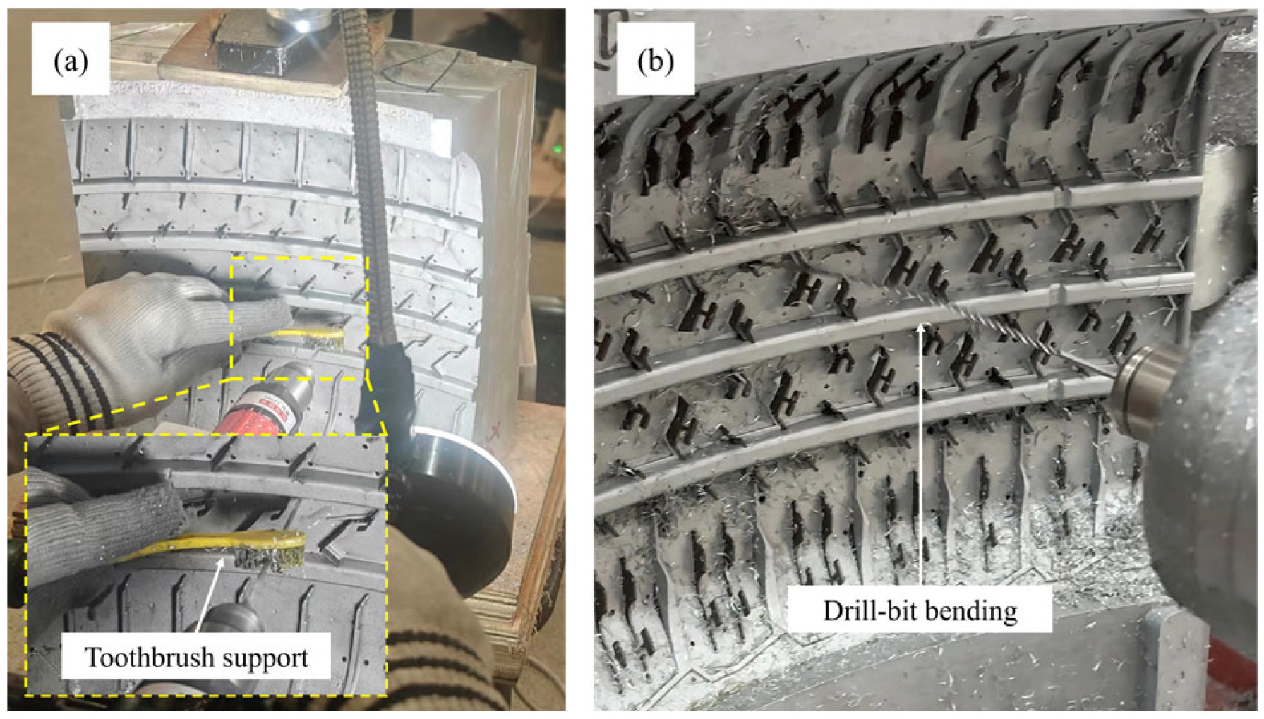
Table 10. Group M represents practical manual-drilling, in which the operator used a toothbrush to support the drill bit (
Figure A5 in
Appendix B) and removed chips after each hole; no lubrication was applied, and 50 drill bits were counted. In manual drilling, operators can regulate the feed rate in real time based on experience. The average tool life was 301.56 holes per drill bit, with a
CV of 6.69%. Group R1 was a failure-case experiment without drill-bushing support, lubrication, or GFTMPC; severe drill-bit bending occurred upon contact with the workpiece (
Figure A5); so, drilling could not be completed and no quantitative tool-life data were obtained. Group R2 used drill-bushing support only, with 10 drill bits counted, resulting in a
Mean of 9.0 and a
CV of 19.88%. Group R3 used drill-bushing support and lubrication but no GFTMPC, and adopted the same staged-drilling strategy as that shown in
Figure 7. Ten drill bits were counted, and the
Mean was 12.5, with a
CV of 18.33%. The smaller sample size in Groups R2 and R3 was adopted because these tests were used only to identify the effects of drill-bushing support and lubrication while reducing unnecessary tool consumption. Group R4 represents the proposed robotic drilling configuration with drill-bushing support, lubrication, and GFTMPC; 50 drill bits were counted, the
Mean increased to 1016.62, while the
CV decreased to 2.68%.
Overall, under the tested configurations, the results show that drill-bushing support is necessary to avoid bending failure of the drill bit, lubrication provides an additional but limited improvement in tool life, and the GFTMPC strategy substantially enhances tool-life performance and consistency by enabling adaptive feed-rate regulation.
- (2)
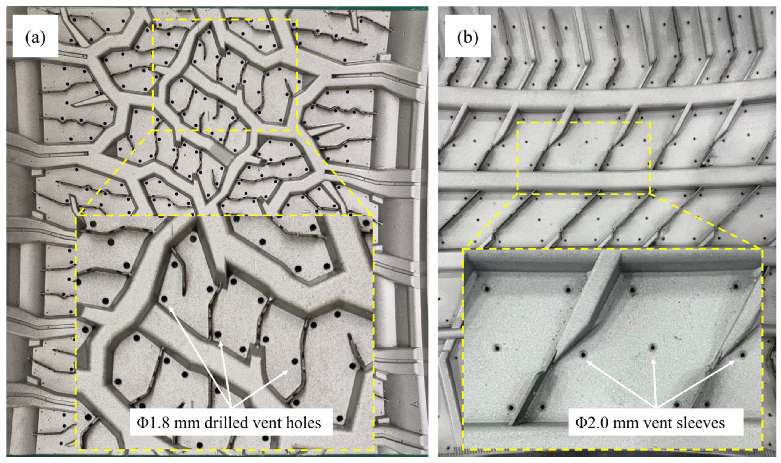
Quality of drilling: As shown in
Figure 27, the drilling results indicate that the vent holes exhibit satisfactory overall drilling quality. The holes have well-defined contours and no visible macroscopic surface defects, such as tearing, chipping, or burr formation. Unlike precision positioning or final assembly holes, tire-mold vent holes mainly serve as gas-venting channels; therefore, hole-axis deviation, hole-wall roughness, and exit burr size are not the primary quality indicators for the initial drilling process. In production, durable vent sleeves with a diameter of 2.0 mm are inserted after the holes are enlarged and reamed. Therefore, the final dimensional accuracy and surface condition are mainly governed by the subsequent finishing process.
However, the hole diameter after drilling may affect the stability of the subsequent sleeve-insertion process. Therefore, in this study, hole-diameter error was selected as the main quantitative indicator for evaluating drilling quality. A total of 50 drilled vent holes were measured using an inner diameter dial gauge, and the results showed that the diameter deviation from the nominal 1.80 mm was within +0.03 mm to +0.11 mm. This indicates that the measured hole-diameter accuracy meets the requirements of this application and provides a suitable basis for subsequent counterboring, reaming, and vent-sleeve insertion.
- (3)
Daily throughput: Each tire-mold workpiece contains, on average, approximately 200 vent holes, with an average drilling depth of 65 mm. When the total drilling cycle is considered, including hole-to-hole positioning and tool retraction for both methods, as well as oil-supply lubrication for robotic drilling, manual drilling requires approximately 20 s per hole, whereas the proposed robotic drilling system requires approximately 35 s per hole. The daily throughput was calculated based on an 8 h working day. For manual drilling, one worker can operate one drilling device; for robotic drilling, one worker can simultaneously supervise three automated robotic drilling systems. As summarized in
Table 11, the daily throughput of manual drilling is 7.2 workpieces, whereas that of the proposed system is approximately 12.34 workpieces. These results indicate that the proposed robotic drilling mode improves the daily throughput per worker by 71.38%.