1. Introduction
Recent advances in servo-actuator technology have made electro-hydrostatic servo-actuators increasingly attractive for the flight control systems of commercial aircraft. Their advantages have been widely recognized by the scientific and engineering communities, and since the 1990s, intensive research has been devoted to this field. As a result, these actuators are now being investigated not only for aeronautical applications, but also for use in many other domains.
Their operating principle is now well established and consists of replacing the centrally supplied onboard hydraulic circuit with a local hydraulic circuit in which a pump directly transfers fluid between the chambers of a hydraulic cylinder. Naturally, the hydraulic circuit also includes other auxiliary components.
Several solutions are available for transferring the fluid between the chambers of the hydraulic cylinder. One option is to use a constant-displacement pump, usually a gear pump, driven by a variable-speed motor (the Fixed Pump Variable Motor (FPVM) configuration). In this case, the hydraulic circuit is simpler, but the motor and its power converter are subjected to high electrical and thermal stress. A second option is to use a constant-speed motor and a variable-displacement pump, usually an axial-piston pump (the Variable Pump Fixed Motor (VPFM) configuration). In this case, since the motor operates at constant speed, it is subjected to lower stress, and a faster actuator response can be obtained through rapid variation in pump displacement. However, continuous motor operation at constant speed also leads to continuous energy consumption, even when the servo-actuator receives no command. A third configuration currently under development is the Variable Pump Variable Motor (VPVM) configuration. This arrangement is usually implemented as a variable-speed motor driving a variable-displacement axial-piston pump. In this case, the pump displacement is not adjusted according to the piston speed of the hydraulic cylinder, but according to the pressure in the hydraulic cylinder, and therefore to the actuator load, in order to reduce the torque at the motor shaft and, consequently, the electrical stress peaks in the motor. However, this control strategy reduces actuator responsiveness when high force is required. In some situations, both high actuation speed and high actuation force may be required simultaneously. Under such conditions, the servo-actuator no longer performs equally well.
A large number of studies in the literature address electro-hydrostatic servo-actuators for applications in both aviation and other fields. A general overview of the issues related to aircraft servo-actuators, including electro-hydrostatic ones, can be found in [
1]. The use of a linear pump to supply an electro-hydrostatic servo-actuator is presented in [
2]. The control of an electro-hydrostatic servo-actuator for submersible applications is discussed in [
3]. Mathematical modeling, dynamic performance analysis, and control of different EHS design variants can be found in [
4,
5,
6]. Various operational aspects of EHS systems have also been examined in the literature. Reference [
7] addresses the electrical insulation of the motors used in EHS servo-actuators, ref. [
8] investigates the optimal design of the hydraulic accumulator, ref. [
9] studies heat transfer in EHS systems, and ref. [
10] focuses on fault detection. Digital control technologies for EHS servo-actuators are discussed in [
11].
In the current context of the energy crisis, the energy efficiency of EHS servo-actuators has become a particularly important issue. EHS solutions with energy recovery capability have been developed, such as those presented in [
12,
13,
14]. Energy consumption in EHS servo-actuators is also analyzed in [
15]. Reference [
16] establishes a link between energy consumption and the control techniques used for EHS servo-actuators, while [
17] proposes an innovative method for improving EHS energy efficiency. Control strategies for EHS servo-actuators used in aviation as well as in other fields have also evolved significantly. Reference [
18] presents a remote-control method, ref. [
19] addresses control in the presence of fluid leakage, and ref. [
20] discusses control methods for EHS servo-actuators used in robotics. Backstepping, state-estimation, and RISE-based control techniques are presented in [
21,
22,
23]. The problem of redundant EHS servo-actuators, which is especially important in aviation, is addressed in [
24]. Control under complex variations in external loads is investigated in [
25], while [
26] examines the use of observers and neural control in EHS systems. The studies presented in [
18,
19,
20,
21,
22,
23,
24,
25,
26] deal predominantly with FPVM configurations. Studies on the control of EHS servo-actuators in VPVM configuration can be found in [
27,
28,
29,
30]. As mentioned earlier, these studies use pump displacement control primarily to reduce motor shaft torque during peak load conditions.
The study presented in this paper builds on the VPFM configurations introduced in [
31], which were compared there with an FPVM configuration. In the VPFM configurations investigated in [
31], pump displacement variation was used to control the motion of the cylinder piston, rather than to limit the torque at the electric motor shaft, as in the VPVM approaches mentioned above. This method ensures good dynamic performance while significantly reducing the stress imposed on the motor and on the drive converter compared with the FPVM configuration. However, it also implies continuous energy consumption during periods in which the servo-actuator remains idle. During long-haul flights, especially under calm atmospheric conditions, flight control servo-actuators may experience long inactive periods during which a considerable amount of energy is wasted.
In this paper, a start-stop system is proposed to switch the servo-actuator off during long idle periods and restart it when a command is received. The main difficulty lies in the high current absorbed by the motor during startup and, consequently, in the severe stress imposed on both the motor and the converter during this phase. If restarts occur relatively frequently, the main advantage of the VPFM configuration, namely the reduced stress on the motor and converter, may be compromised. To overcome this drawback, the use of a hydraulic accelerator device is proposed to assist motor startup. Once the electric motor of the servo-actuator has started, the accelerator device is recharged and then disconnected from operation, remaining on standby until the next startup is required.
The start current peaks appear in any kind of electric motor. In this work, we considered a DC electric motor. It is true that the start current peaks can be limited using electronic devices, but these peak limitations lead to a slower motor start and a very long time response to a command that appears after an idle period. This situation is not permitted in aviation. Command delays of tenths of seconds can lead to dangerous flight situations. So, we try to find a solution to reduce the start current peaks and keep the servo dynamic undecayed as much as possible.
In addition to the studies presented in [
13,
14] that address the energy recovery for FPVM configurations, this work tries to reduce energy consumption for a VPFM configuration. Studies in [
13,
14] use the four-quadrant approach to restore the hydraulic energy in the EHS’s hydro-accumulator when it works in the one and three quadrants. FPVM configuration stops the electric motor in the idle regime, so it does not need to use a start-stop system, but the electric motor and the feeding converter are subject to great demands during the EHS functioning. VPVM versions are studied in the literature [
27,
28,
29,
30] in order to reduce the necessary torque when the EHS encounters hard regimes—there are load-sensing EHSs, but they do not address the problem of the energy lost in the idle regime when the electric motor keeps working. This work tries to make a trade-off between the good dynamic performances of the VPFM configuration, excellent for flight control systems and energy saving during the idle regimes. This approach, also very simple, was not yet considered in the literature. The proposed configuration uses two hydro-accumulators that charge and discharge alternatively. This work studies only the start-stop application of this device, but the configuration has the potential to be used also as an energy recovery device, as in [
13,
14], but for a VPFM configuration. In [
13], it is mentioned that high inverse currents appear when the electric motor of the EHS is forced to work in a generator regime when the speed and force of the EHS are in opposition. These currents will be observed in the simulations presented in this work. The inverse currents mean high inverse power that could damage the feeding converter. In the absence of an energy-recovering device, this inverse power is dissipated on a high-power resistor that weighs about 2 kg [
13]. The proposed configuration has the potential to solve the inverse power problem along with the lost power in the idle regime. But as we stated before, it will be studied in future work.
The effectiveness of using a start-stop system assisted by a hydraulic accelerator is investigated in this paper by means of numerical simulation in SIMCENTER AMESIM, version 2304, for the VPFM-type EHS servo-actuator configurations studied in [
31]. The mathematical models used in the simulations are those implemented in SIMCENTER AMESIM and can be found in [
32]. There are mathematical models widely used in the scientific world that have been proven very efficient and offer good precision. Regarding the physical parameters used in the simulations, found in [
31], we will not introduce them again here.
This work presents the effect of the start-stop system with accelerator along a control block that synchronizes the functioning of the system. For the simulations, a control scheme that generates the command signals for the distributor and the electric motor is implemented in AMESIM. For experimental tests, this scheme has to be implemented as an electronic control block.
2. Operating Principle of the Acceleration System
The proposed improvement of VPFM-type Electro-Hydrostatic (EHS) servo-actuators aims to reduce the energy losses occurring during idle periods, when the servo-actuator remains inactive while the main pump motor continues to operate. The solution consists of implementing a start–stop strategy, in which the main pump motor is switched off as long as the servo-actuator is in an idle state.
In this way, the advantages of FPVM servo-actuators, characterized by zero energy consumption during idle operation, are combined with the advantages of VPFM servo-actuators, which provide improved control performance and reduced electrical stress on the motor of the EHS system. Ideally, a VPVM-type control would be preferred; however, such a solution is difficult to implement in order to control the servo-actuator movement both by motor speed and pump displacement variation, not only for electric motor torque limitation. The proposed approach can therefore be considered a semi-VPVM solution.
The idea of stopping the main pump motor is not, in itself, complex, but it introduces the issue of increased stress on both the motor and the power converter during start-up phases. Although start-up events occur less frequently than in FPVM servo-actuators, resulting in lower overall stress levels, rapid activation from an idle state still imposes significant loads on both the motor and the converter, potentially reducing their service life.
To reduce motor stress during start-up, a hydraulic acceleration device is introduced, designed to assist the motor in this phase and to limit the current peaks that typically occur. In this way, on the one hand, the energy consumed by the motor during idle periods is reduced, and on the other hand, the lifetime of the main pump motor and the converter is increased due to the reduction in peak operating stresses.
In the case of commercial aircraft, during long-duration flights in stable atmospheric conditions, where control inputs remain in neutral position for extended periods, the energy savings achieved through this solution become significant, while maintaining the advantages of VPFM-type servo-actuators.
The operating principle of the system can be summarized as follows:
- -
the control system automatically stops the main pump motor after a predefined inactivity period (e.g., 2 s);
- -
when a command is received after an idle period, the hydraulic accelerator is activated first, accelerating the main pump to a predefined rotational speed;
- -
after the pump reaches a suitable speed, the electric motor of the main pump is engaged, ensuring the continued operation of the servo-actuator. In this way, a significant reduction in current peaks occurring during motor start-up under load is achieved.
The acceleration device must ensure rapid start-up of the main pump in order to guarantee prompt execution of the command received by the servo-actuator. At the same time, it must allow an effectively unlimited number of start cycles.
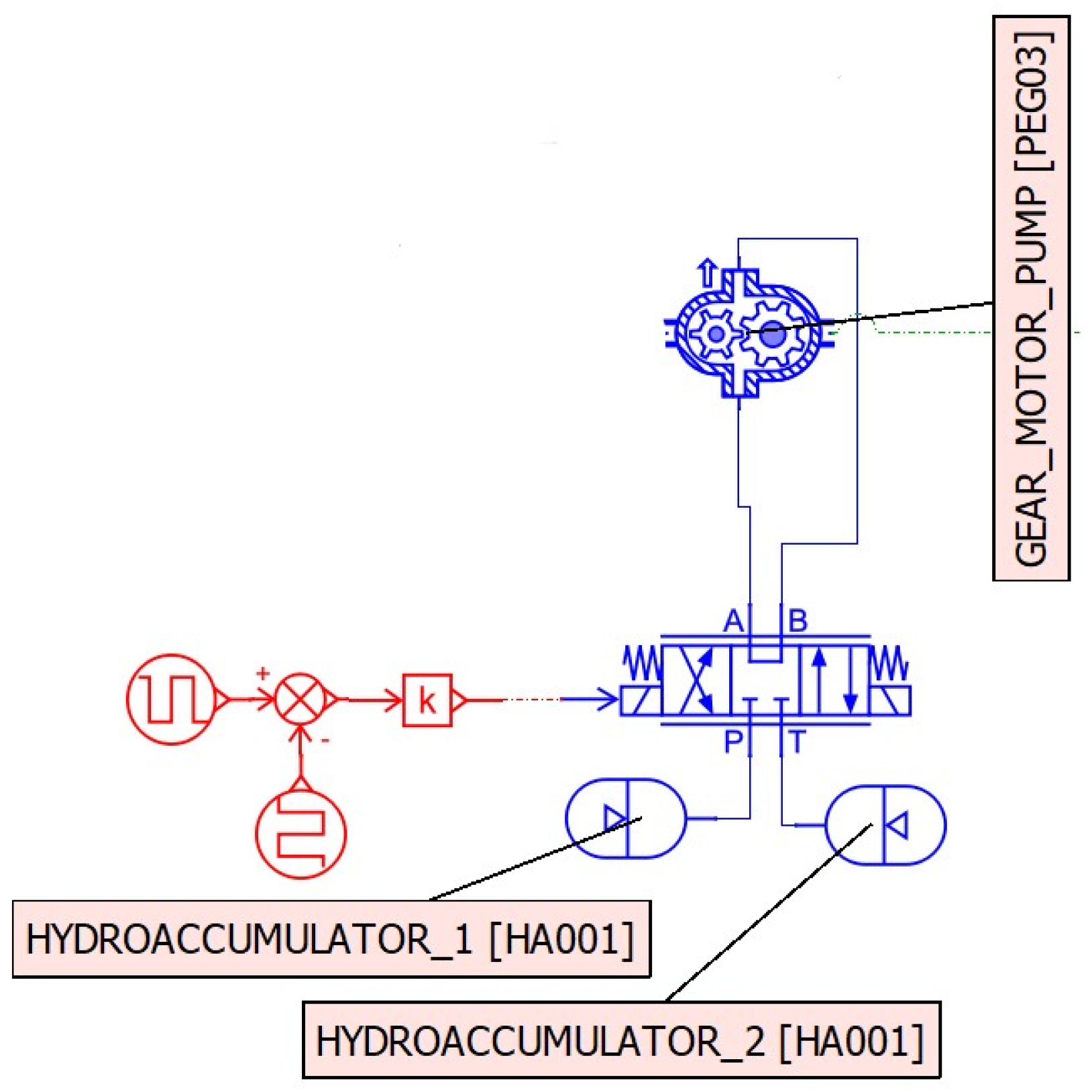
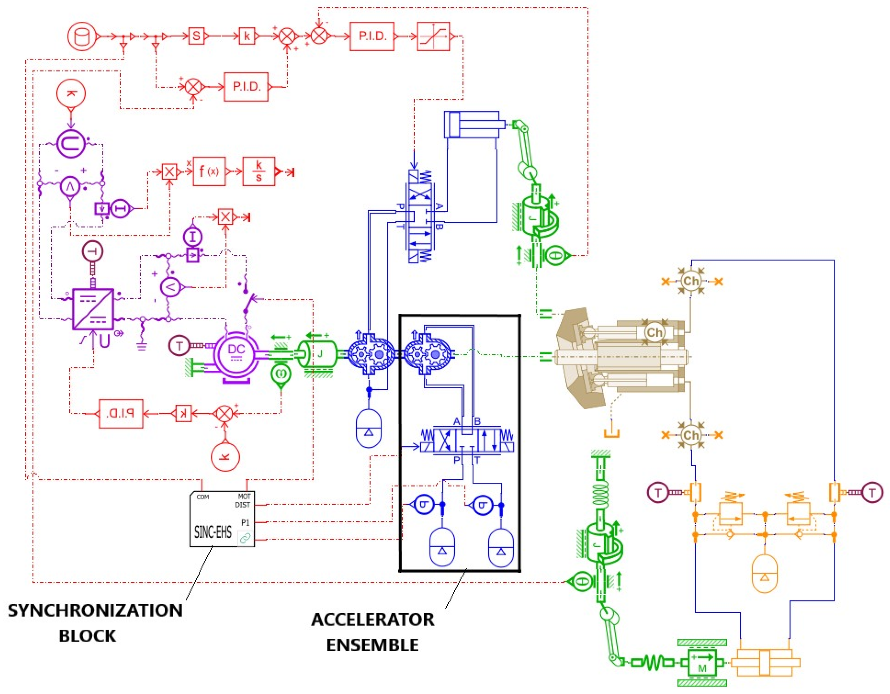
For this purpose, the acceleration device consists of two hydraulic accumulators, a directional control valve, and a gear-type hydraulic machine, which operates either as a hydraulic motor or as a pump, depending on the operating mode (see
Figure 1).
In the initial state, when the servo-actuator is at rest, one of the hydraulic accumulators is discharged (for example, at a pressure of 30 bar), while the other is charged to the maximum pressure (for example, 250 bar).
When a command is received for the servo-actuator, the directional control valve supplies the hydraulic motor in the acceleration direction, using fluid from the charged accumulator. The gear-type hydraulic motor is mounted on the same shaft as the main pump of the servo-actuator, thus ensuring the acceleration of the main pump.
Once the motor reaches a sufficient rotational speed, the electric motor is engaged, which then ensures the continued operation of the servo-actuator.
The directional control valve remains in the same position for a certain period, until the gear-type hydraulic machine, now operating in pump mode, charges the initially discharged accumulator up to 250 bar, after which it returns to the neutral position. The control valve considered in the simulations in this work was a spool valve for simpler modeling in SIMCENTER AMESIM. This valve works in a commutation regime, only on–off. Because the spool valve generally has higher liquid losses than other valve types, it is possible that the charged hydro-accumulator may be discharged through liquid losses. In order to avoid the hydro-accumulator discharge, control valves with very low liquid losses could be used for experimental implementation. One kind of valve with very low losses is the poppet valve. The overall performance of the system will not be influenced in this case, and the uncontrolled hydro-accumulator discharge will be avoided.
The gear-type hydraulic machine will then continue to operate under no-load conditions, with minimal hydraulic resistance.
The accumulator that was initially charged becomes discharged, while the one that was initially discharged is now charged. The acceleration device is thus prepared for a new start from a subsequent idle condition. At the next start, the control valve will be actuated in the opposite direction compared to the initial one, ensuring that the fluid from the accumulators provides the correct direction of rotation for the main hydraulic pump.
The shutdown of the electric motor of the main pump can only be performed if two conditions are simultaneously fulfilled: the servo-actuator has not received any command for a period longer than the predefined threshold (in this example, 2 s), and the accumulator that was initially discharged has reached the pressure of 250 bar, ensuring the capability for the next start. As will be shown in the simulations, the charging process of the initially discharged accumulator occurs in a very short time and does not require additional operation of the main motor beyond what is necessary to execute a command.
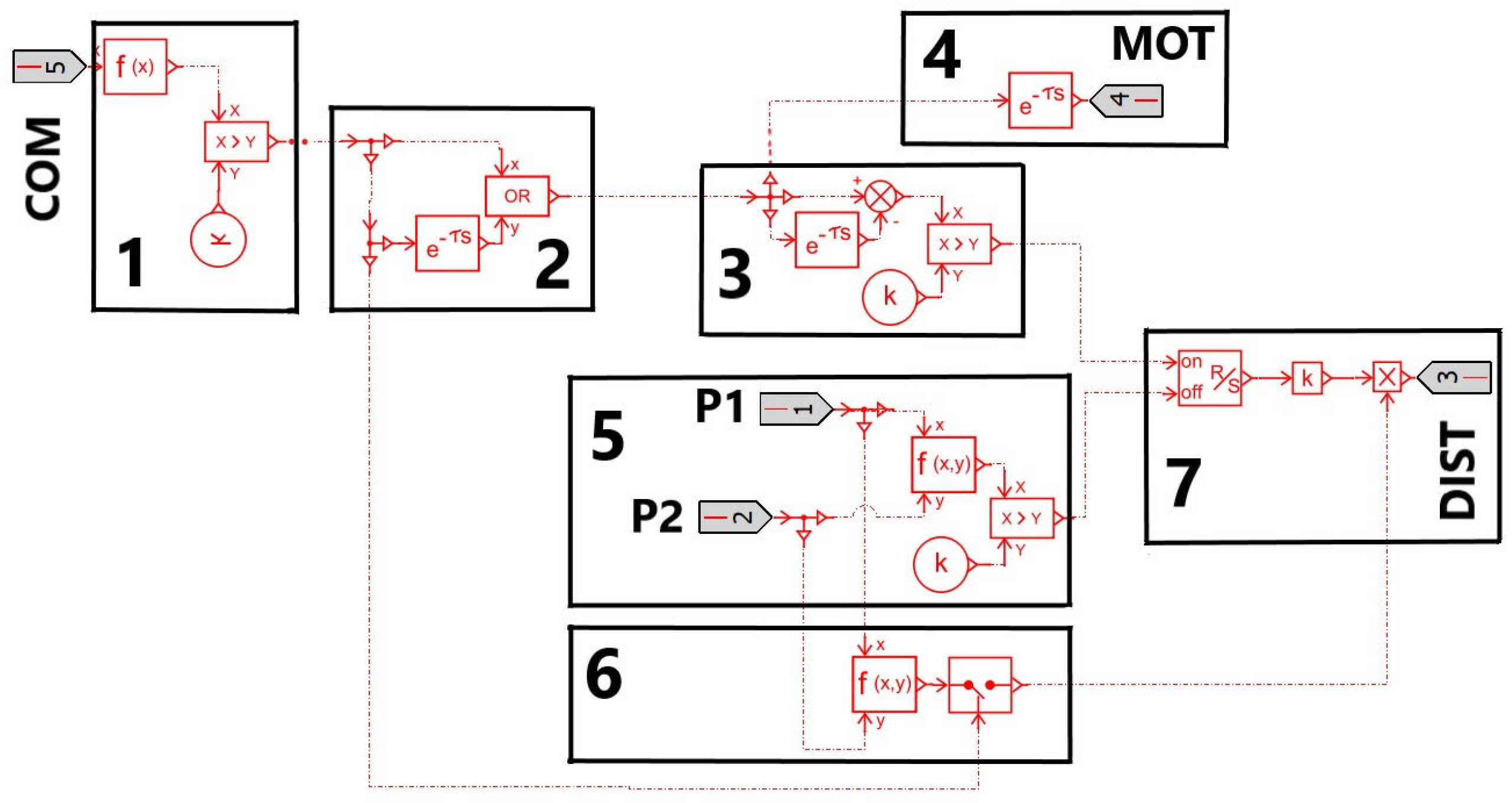
The scheme of the control block is presented in
Figure 2, and the corresponding signals are presented in
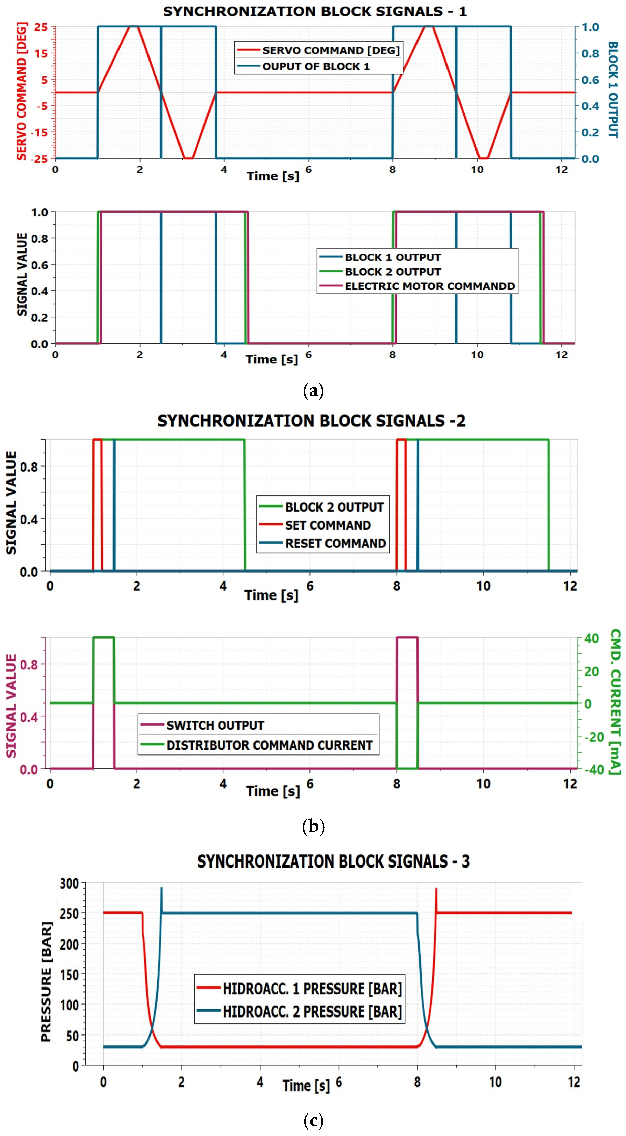
Figure 3.
The command received from the stick (red line in
Figure 3a) is passed through an abs(x) function, and after that, compared with a threshold level in order to reject the possible low-level parasitic signals (sub-block 1). It results in a signal that indicates the period of EHS activity, but when the command passes through zero, there are some discontinuities (line blue in
Figure 3a). In order to eliminate these discontinuities and to ensure a period for the motor functioning after the command rests at idle, in sub-block 2, the output signal from sub-block 1 is delayed and then applied to an OR logical function with the original signal. The delay period is equal to the period desired to keep the electric motor in function after the command rests to idle.
The output of sub-block 2 represents the activity period of the EHS (green line in
Figure 3a). As we mentioned in the presentation of the accelerator functioning sequence, the electric motor starts only after a delay period. In this period, the main pump is accelerated by the energy in hydro-accumulators. So, a delay of 0.07 s is applied in the sub-block 4, and after that, the electric motor is fed (magenta line in
Figure 3a).
In sub-block 3, the output of sub-block 2 (line green in
Figure 3b) generates an impulse that switches on the command of the distributor (line red in
Figure 3b). The switch output is amplified to the level required by the distributor output, and the command signal polarity is selected. In sub-block 6, a sampler reads the relation between the pressures in the hydro-accumulators. In fact, it samples the output of the function
sign(
p1 −
p2). The output of the sampler is multiplied by the amplified signal from the switch, resulting in the “on” command signal for the distributor (line red in
Figure 3b). The sampling moment is the EHS command moment received from the stick.
In this manner, the distributor is opened, and the electric motor is accelerated to a convenient speed during the delay period generated in sub-block 4. After this period, the electric motor is fed and enters the normal functioning regime. Now the electric motor sustains the EHS functioning, the hydro-accumulator 1 is discharged, but the distributor remains open, and the hydro-accumulator 2 is charged.
In sub-block 5, the maximum between
p1 and
p2 is compared with the threshold for hydro-accumulator charging. When this threshold is reached, the “off” signal for the switch is generated, and the distributor closes (line blue in
Figure 3b). The switch output is the green line in
Figure 3b, and the command signal for the distributor is the magenta line in
Figure 3b. The accelerator device is now prepared for a new start.
As will be further demonstrated through simulations, the charging of the initially discharged accumulator leads to the occurrence of current peaks; however, these are significantly lower than those associated with starting the main motor without the acceleration device. By adopting an appropriate servo-actuator configuration, these peaks can be reduced by approximately three times compared to the case without acceleration.
Furthermore, the proposed solution was validated through numerical simulations for three VPFM-type EHS servo-actuator configurations presented in [
31]. The configuration names, as well as the servo-actuator parameters, were adopted directly from [
31]. The implementation of the acceleration device was investigated for all three configurations.
3. VPFM-Type Servo-Actuator–HR Configuration with Accelerator
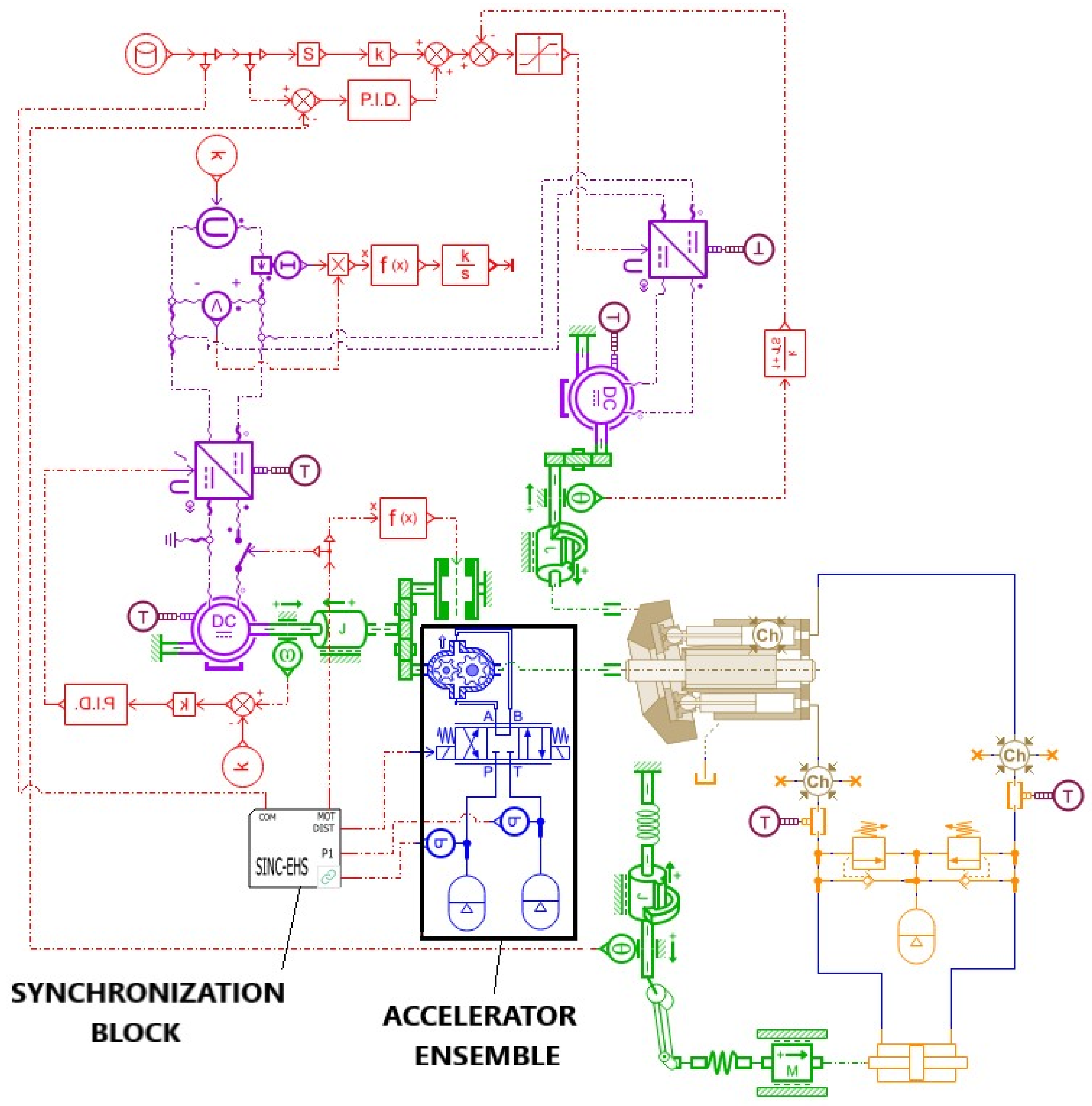
The VPFM–HR configuration consists of an EHS servo-actuator equipped with a variable displacement pump and a constant-speed motor, in which the control of the pump swashplate is achieved by means of an auxiliary electric motor and a mechanical device with a high transmission ratio between the motor and the pump swashplate. Such a device, considered in [
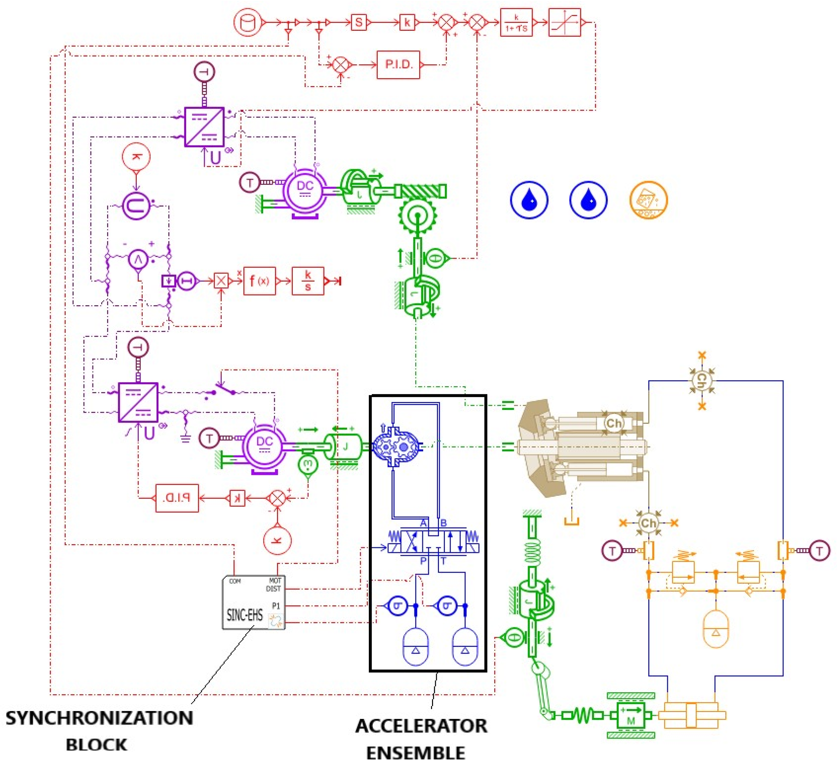
31], is the worm gear mechanism. The simulation scheme for this type of servo-actuator is presented in
Figure 4.
All system parameters are identical to those used in [
31], with the only addition being the acceleration device. The high transmission ratio between the auxiliary motor and the swashplate of the main pump ensures a very low reverse transmission of forces acting on the swashplate, originating from the motion of the pistons.
As will be shown in the following, this results in the operation of the main pump having no significant influence on the overall behavior of the servo-actuator, while the movement of the pump swashplate remains smooth, without significant vibrations.
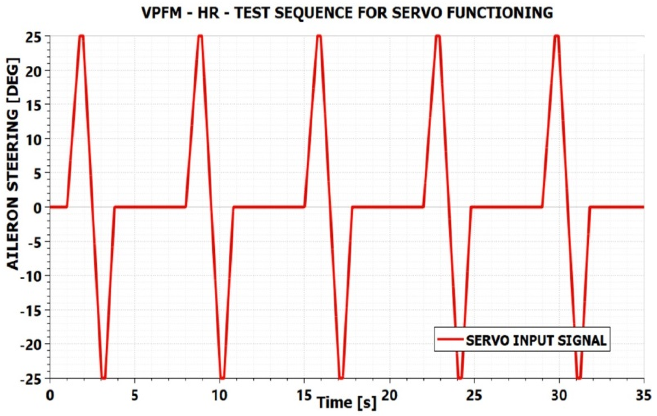
The test sequence for the operation of the servo-actuator with start–stop functionality and acceleration device is presented in
Figure 5.
The test sequence consists of deflections at maximum speed from the neutral position to the maximum position, followed by a return, also at maximum speed, to the minimum position, and then back to the neutral position, again at maximum deflection speed. These sequences are separated by intervals of approximately 4 s, during which the servo-actuator remains in the neutral position, in idle mode.
The maximum deflection speed for which the considered servo-actuator was designed is 35 deg/s. The servo-actuator starts operating immediately upon detection of the command, in accordance with the sequence specified in
Section 3. Although it was initially proposed that the operation of the main pump motor be interrupted after 2 s of inactivity, in order to reduce the simulation time, it was assumed here that the shutdown occurs after 0.7 s of inactivity. The sequence is repeated five times, with a period of 7 s.
The delay between the moment of servo-actuator activation, defined by the command of the accelerator directional valve, and the moment of engagement of the main motor supply was determined iteratively based on the performed simulations. For the servo-actuator analyzed in this study, a convenient delay of 0.07 s was obtained. This delay was used consistently throughout all simulations presented in this paper.
For the sizing of the accelerator components, the number of teeth, width, and module of the gear wheels were taken into consideration, and consequently, the displacement of the gear-type hydraulic machine was used as an accelerator. The volume of the hydraulic accumulators was also considered.
A pressure of 250 bar was assumed for the accumulators when fully charged, and a gas precharge pressure of 30 bar was considered. The objective was to obtain the lowest possible current peaks during the start-up of the main motor of the VPFM–HR EHS servo-actuator, but also to obtain a configuration as compact as possible.
In order to determine an accelerator configuration as good as possible, several variants were analyzed, with parameters presented in
Table 1. The last two columns of
Table 1 show the values of the current peaks and rotational speed obtained for each accelerator configuration.
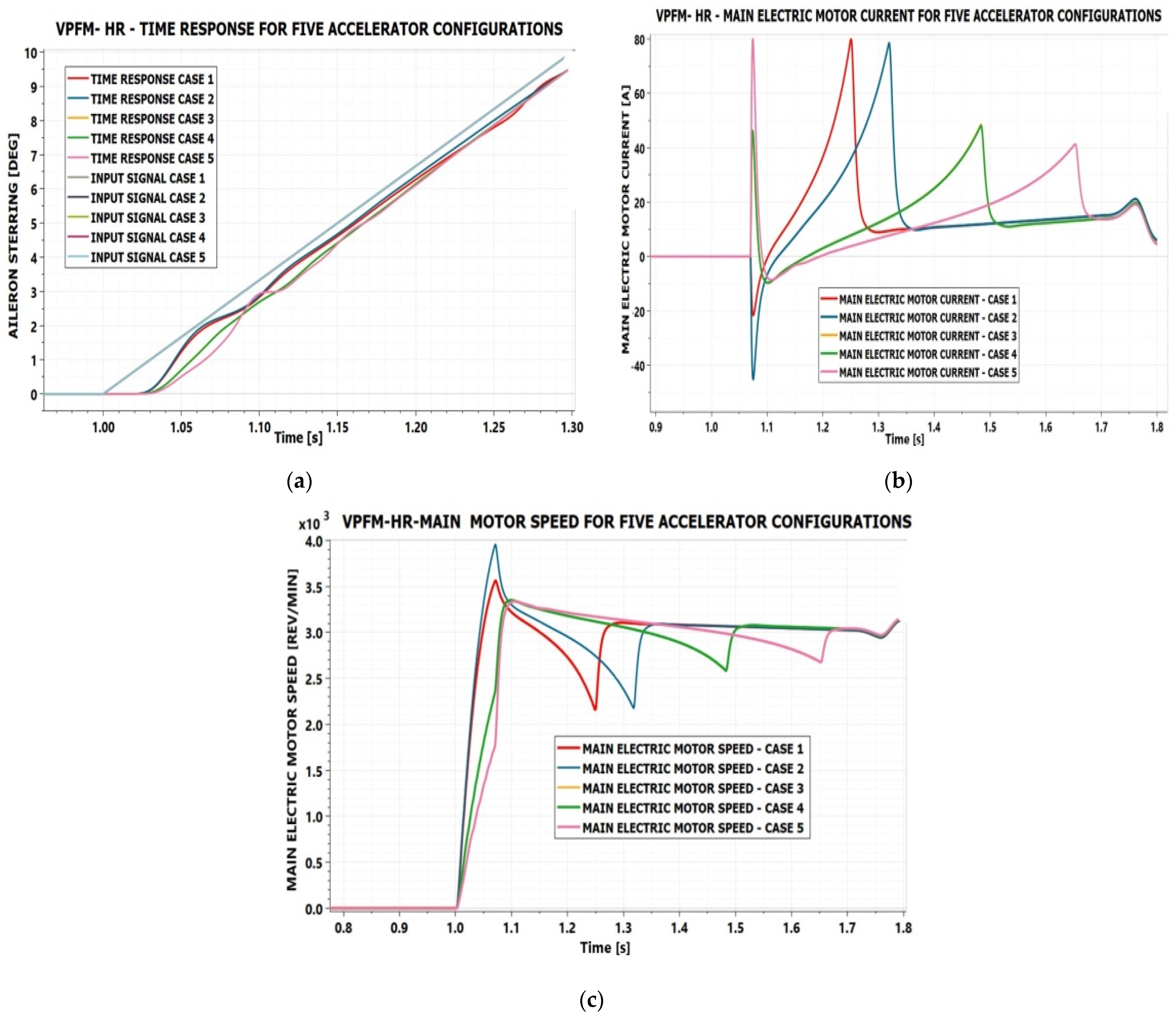
The behavior of the servo-actuator with start–stop functionality and different acceleration device configurations is presented in
Figure 6.
From
Figure 6a, it can be observed that the use of a gear-type hydraulic machine with a larger displacement (approximately 16 cm
3, cases 1 and 2) leads to a faster acceleration of the servo-actuator, reducing the delay in the time response during the start-up phase. The maximum speed reached by the main motor, accelerated in this way, exceeds the nominal value of 3000 rev/min considered in the design of the servo-actuator (
Figure 6c).
For these cases, the current peak that typically occurs at the moment of supplying the main electric motor completely disappears. At first glance, this appears to be a very good solution.
However, as the second accumulator begins to charge in preparation for a new start, current peaks similar in magnitude to those obtained when using a gear-type hydraulic machine with small displacement (case 5) are observed. The torque required at the shaft of the hydraulic machine to charge the accumulator to 250 bar increases with the displacement of the hydraulic machine. This explains the large current peak that occurs when the pressure of 250 bar is reached in the second accumulator.
The difference between cases 1 and 2 lies in the volume of the accumulators. In case 1, a volume of 0.3 L was considered, while in case 2, a volume of 0.4 L was used. Due to the larger accumulator volume in case 2, a higher acceleration of the main motor is obtained during start-up, but the pressure peaks reached when the second accumulator is fully charged remain the same. These peaks are only shifted in time, since the 0.4 L accumulator charges more slowly than the 0.3 L one.
Cases 3 and 4 consider gear-type hydraulic machines with approximately the same displacement (around 8 cm
3), but with different gear widths and numbers of teeth, while maintaining the same module. The resulting curves for these cases overlap in
Figure 6a–c, making them indistinguishable. This leads to the conclusion that, for the operation of the servo-actuator, the displacement of the gear-type hydraulic machine is the determining parameter, rather than the number of teeth, gear width, or module considered individually.
In these two cases, the first current peak appears at the moment of supplying the main motor, since the acceleration does not reach the nominal speed. The motor continues to accelerate to the nominal speed through the starting current. A second current peak occurs when the pressure in the second accumulator reaches 250 bar. These two peaks are approximately equal, but smaller than those obtained in cases 1, 2, and 5.
Case 5 considers a gear-type hydraulic machine with a smaller displacement (approximately 5 cm3). In this case, the main electric motor is not sufficiently accelerated, and a large current peak occurs when it is connected to the power supply. After reaching the nominal speed, the current decreases, and when the pressure in the second accumulator reaches 250 bar, a second current peak appears, but with a lower value than in the other cases. However, the first current peak is comparable to those observed in cases 1 and 2 when the pressure of 250 bar is reached in the second accumulator.
The reduction in the first current peak in case 5 can be achieved by considering accumulators with larger volumes and by increasing the delay between the command of the directional valve and the connection of the electric motor to the power supply. This would allow a stronger acceleration of the electric motor during start-up and a reduction in the current peak. However, this leads to an increase in the size and weight of the acceleration device, which is not desirable. Although the gear-type hydraulic machine would be smaller, the dimensions of the two accumulators would increase.
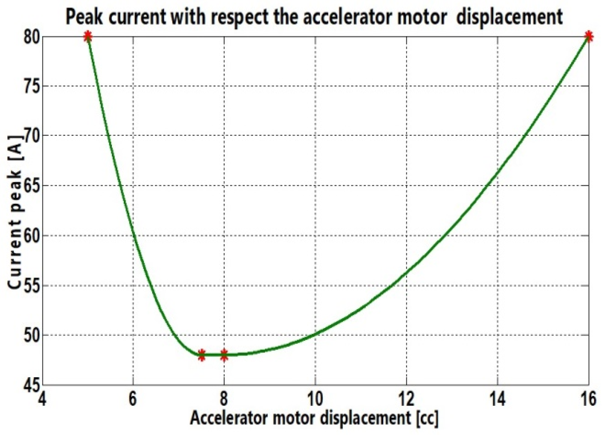
A variation estimated based on the obtained data, of the maximum current peak value as a function of the displacement of the hydraulic machine, is presented in
Figure 7.
A conclusion that can be drawn from the above analysis is that a too small displacement of the accelerator motor results in insufficient acceleration of the motor and a high current peak due to the start-up of the electric motor, while a too large displacement leads to a high current peak during the charging of the second accumulator. There exists an optimal displacement that minimizes the current peaks. Such a displacement results in current peaks of comparable magnitude, both due to the start-up of the electric motor and the charging of the second accumulator. However, these peaks are lower than those obtained for the other configurations.
Regarding the volume of the hydraulic accumulators, it is observed that accumulators with a volume of 0.3 L are sufficient to ensure the proper operation of the start–stop system with the acceleration device. As the accumulator volume increases, the motor is accelerated to a higher speed during start-up, leading to a reduction in the current peak. However, larger accumulators result in increased size and weight of the overall EHS servo-actuator. Based on the results obtained, configurations 3 and 4 can be considered the most suitable for the analyzed servo-actuator.
Between these two variants, configuration 4 uses a gear machine with a smaller number of teeth, even though the gear width is 2 mm larger. Such a hydraulic machine is considered more compact and lighter; therefore, the best solution corresponds to case 4 in
Table 1. In the simulations presented further for the VPFM–HR servo-actuator, the accelerator parameters corresponding to this configuration were used.
Further,
Figure 8 presents the behavior of the VPFM–HR servo-actuator over the entire test sequence defined in
Figure 5. Three cases were considered: the basic VPFM–HR configuration studied in [
31], the VPFM–HR configuration with start–stop functionality but without an acceleration device, and the VPFM–HR configuration with both start–stop functionality and an acceleration device.
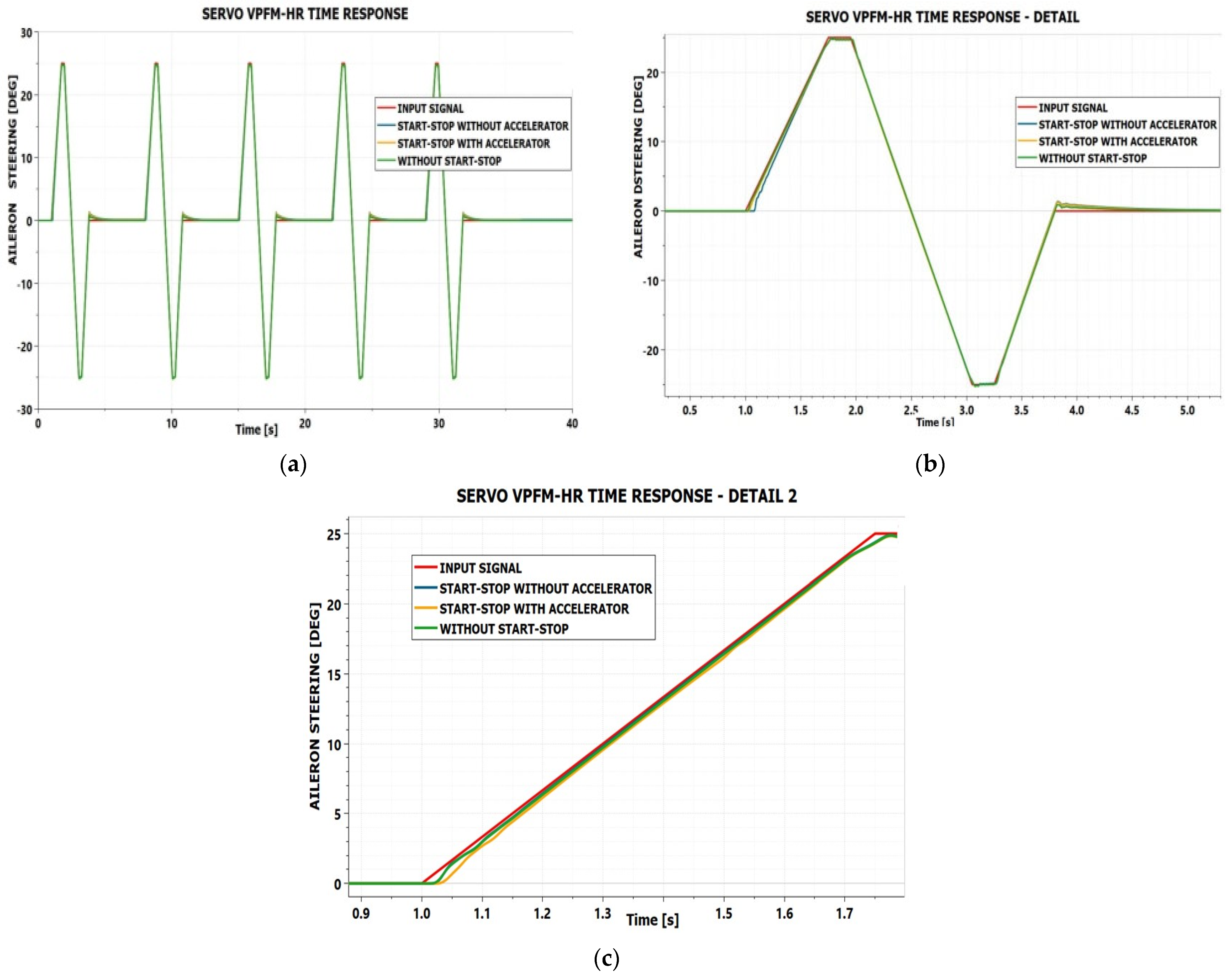
From
Figure 8a–c, it can be observed that the time responses are practically identical for the three cases, except for very small differences during the acceleration phase of the electric motor. The best response is obtained in the case without the start–stop system, as the electric motor is already operating at nominal speed and the servo-actuator can respond promptly to the command. The case with the start–stop system, without acceleration, behaves practically identically with the case without start-stop. The response curves are overlapping in
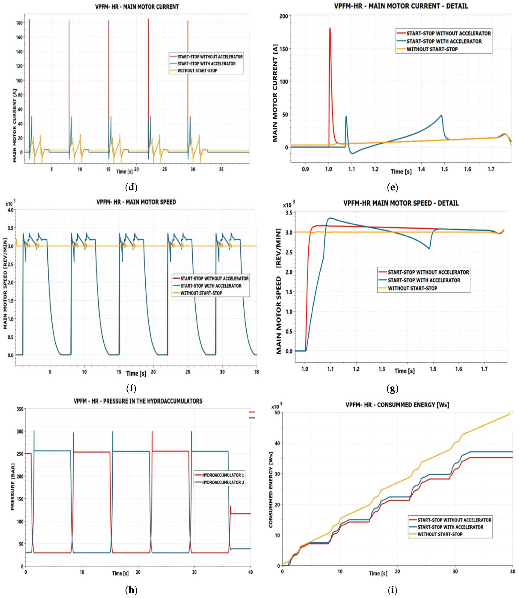
Figure 8c, but the current peak presented in
Figure 8e is 180 A. The case with the start–stop and acceleration device exhibits a slightly larger delay during the start-up phase, but afterward tends toward the same behavior as the other two cases.
Figure 8d,e highlight one of the main advantages of the start–stop system with an acceleration device. In the case without start–stop, the variation in the main motor current follows only the load variations in the servo-actuator. In the case of a start–stop without an acceleration device, a current peak of approximately 180 A appears during start-up. In the case of a start–stop and acceleration device, two current peaks occur, each with a value of approximately 50 A. A reduction of about 3.6 times in the start-up current peak can thus be observed.
Such behavior results in significantly reduced stress on the main motor during start-up and ensures reliable operation of the servo-actuator when subjected to a large number of start cycles during flight. It is thus demonstrated that the servo-actuator can be operated in a start–stop regime without being excessively stressed by repeated start-ups. This stress level is also considerably lower compared to that of an FPVM-type EHS servo-actuator, where control is achieved by varying the speed of the main pump motor.
Stopping the main motor during idle phases allows significant energy savings, especially during long-duration flights in stable atmospheric conditions, where autopilot interventions are minimal. The percentage of energy saved depends on the duration of the idle periods of the servo-actuator.
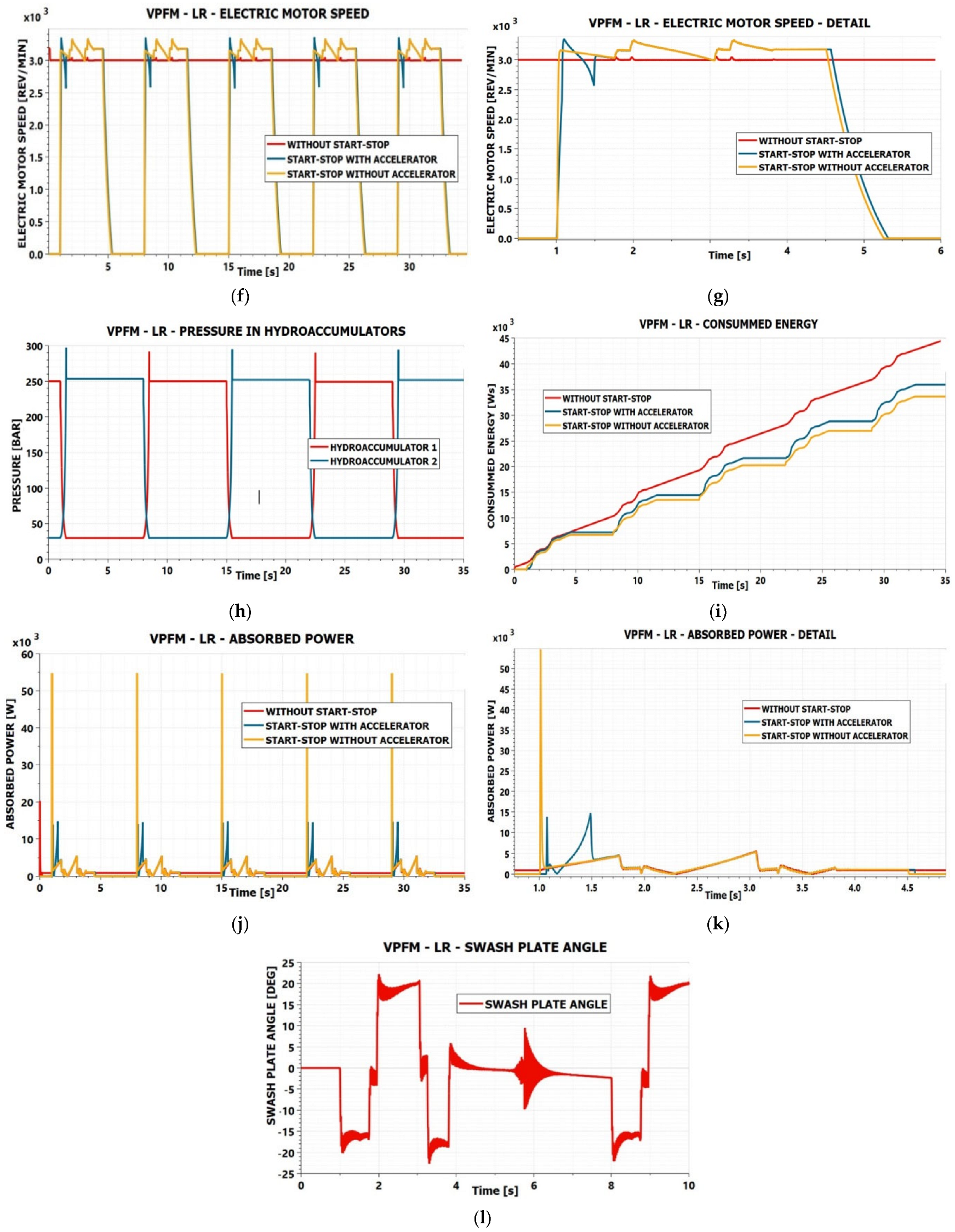
Figure 8f,g present the variation in the main motor speed. In the case without start–stop, only small speed variations occur at load peaks. In the case of a start–stop without an acceleration device, speed variation appears during start-up, in addition to the same small variations at load peaks. In the case of a start–stop and acceleration device, larger speed variations occur during start-up, due to the acceleration of the motor and the subsequent charging of the accumulator. During the accumulator charging phase, a significant speed drop is observed, as this represents an additional load on the main motor.
Figure 8h presents the variation in the pressure in the two hydraulic accumulators for the start–stop system with an acceleration device. The correct operation of the system can be observed, with the two accumulators charging and discharging alternately up to the considered pressure of 250 bar.
Figure 8i presents the energy consumed in the three considered cases. The highest energy consumption occurs in the case without start–stop, as the continuous operation of the main pump during idle periods leads to significant energy losses.
The case with start–stop but without an acceleration device results in the lowest energy consumption; however, the current peaks during start-up are very high, placing considerable stress on both the motor and the power converter. In the case of a start–stop and acceleration device, an additional energy consumption appears compared to the case without an acceleration device, due to the energy required for charging the accumulator. Part of this energy is recovered during the next start-up, but due to system losses, the overall consumption remains higher.
Even under these conditions, for the analyzed case, an energy saving of approximately 25% is achieved. This percentage varies significantly depending on the duration of the idle periods.
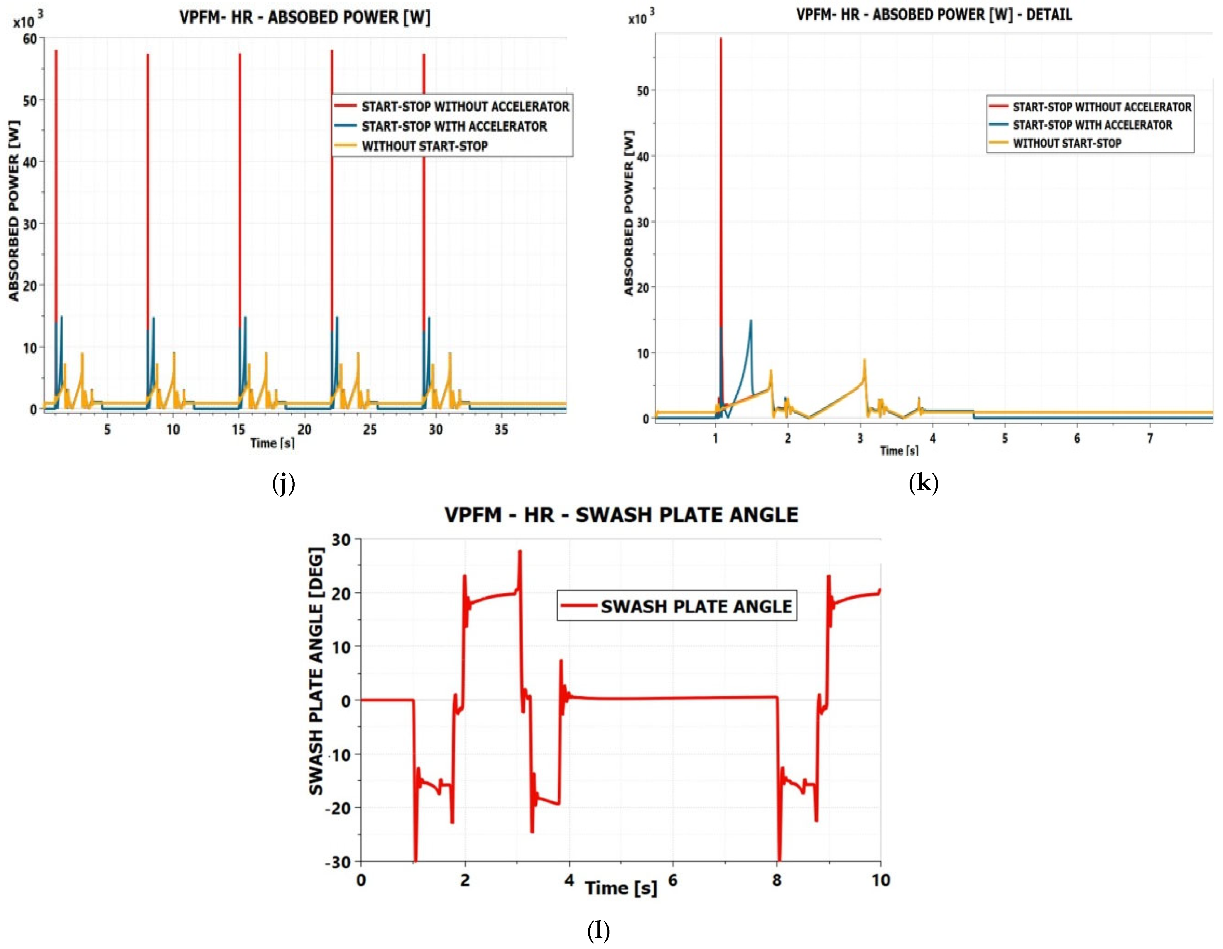
Figure 8j,k highlight the power peaks absorbed by the servo-actuator. These peaks follow the current peaks during operation. In the case without start–stop, power peaks are small and are caused only by load variations. In the case of the start–stop and acceleration device, power peaks are higher than those caused by load variations, but only by approximately a factor of two. In contrast, in the case without an acceleration device, power peaks are approximately six times higher than those associated with load variations. It should be noted that both the absorbed power and the consumed energy were calculated for the entire servo-actuator, not only for the main motor.
Figure 8l presents an aspect less relevant from an energy perspective, but important from the control standpoint. The variation in the swashplate angle follows the motion of the control surface without significant self-oscillation. This favorable behavior is due to the fact that the transmission system between the control motor and the swashplate does not transmit significant forces back from the swashplate to the motor, thus not disturbing its operation.
In fact, the worm gear transmission does not transmit any load back from the swashplate to the motor, being a self-locking transmission system. This aspect is highlighted here, as in the following case, the unfavorable influence transmitted from the swashplate to the control motor will become evident.
4. VPFM-Type Servo-Actuator–LR Configuration with Accelerator
The VPFM–LR servo-actuator is similar to the VPFM–HR configuration, the only difference being that the motion transmission from the auxiliary motor controlling the main pump to its swashplate is achieved through a mechanism with a low transmission ratio.
In [
31], a gear transmission with a transmission ratio equal to three was considered. The same servo-actuator is analyzed in this paper, with the addition of the start–stop system and acceleration device. The simulation scheme is presented in
Figure 9.
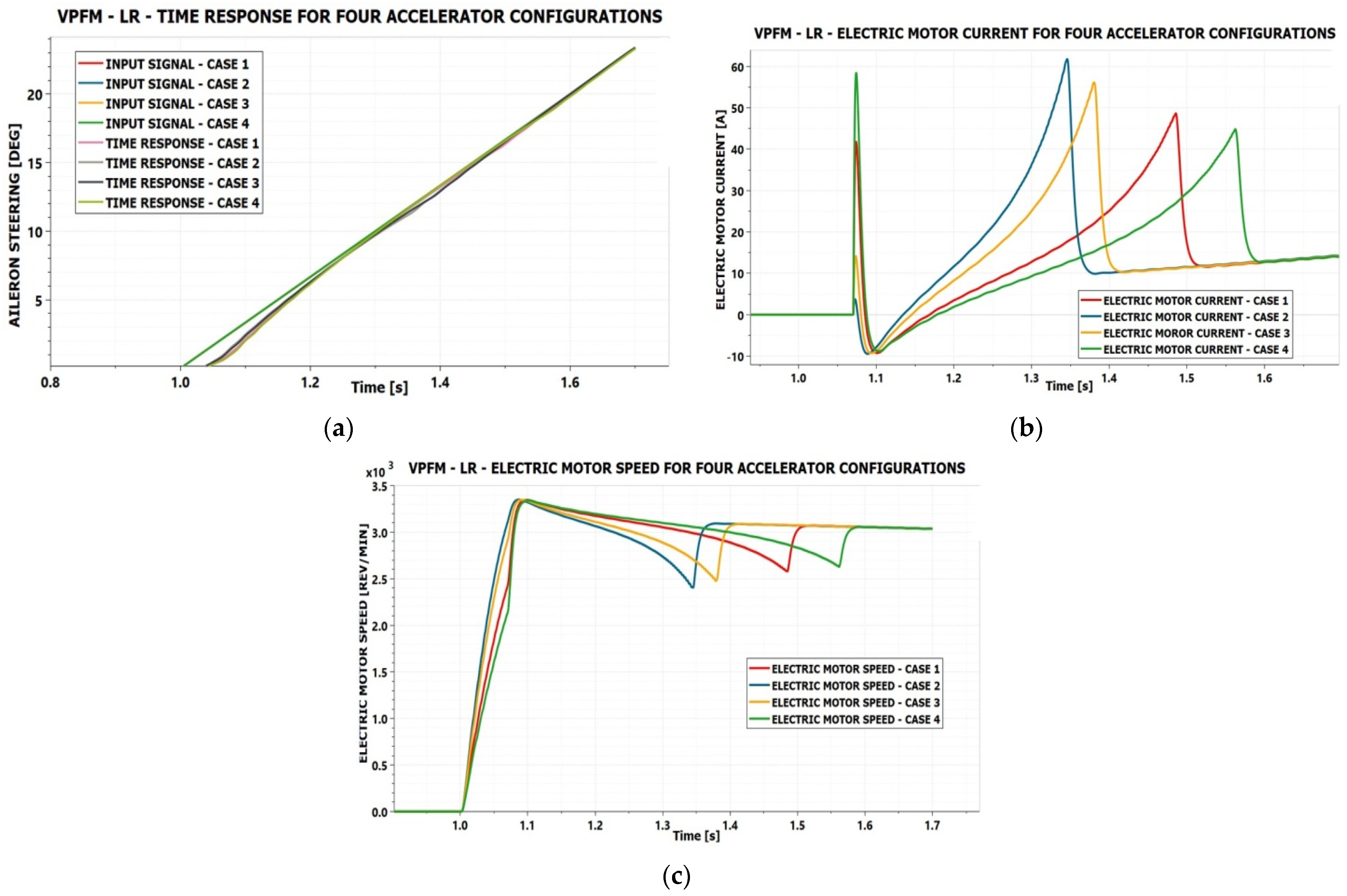
Since the actuation parameters were kept the same as in the previous case, only four configurations were selected for the estimation of the best parameters of the acceleration device components, as presented in
Table 2.
Based on the experience gained in the previous case, the displacement range for which simulations were performed was reduced to between 6.5 cm
3/rev and 11 cm
3/rev. From
Figure 10a, it can be noticed that the differences between the time responses for the four analyzed configurations are negligible.
By analyzing
Figure 10b, it can be seen that the most advantageous configuration corresponds to case 1, with a displacement of the gear-type hydraulic machine of 7.5 cm
3/rev, similarly to the VPFM–HR case. This result was expected, given that the constructive differences between the two servo-actuator configurations are minor.
The differences between the obtained speed peaks, as shown in
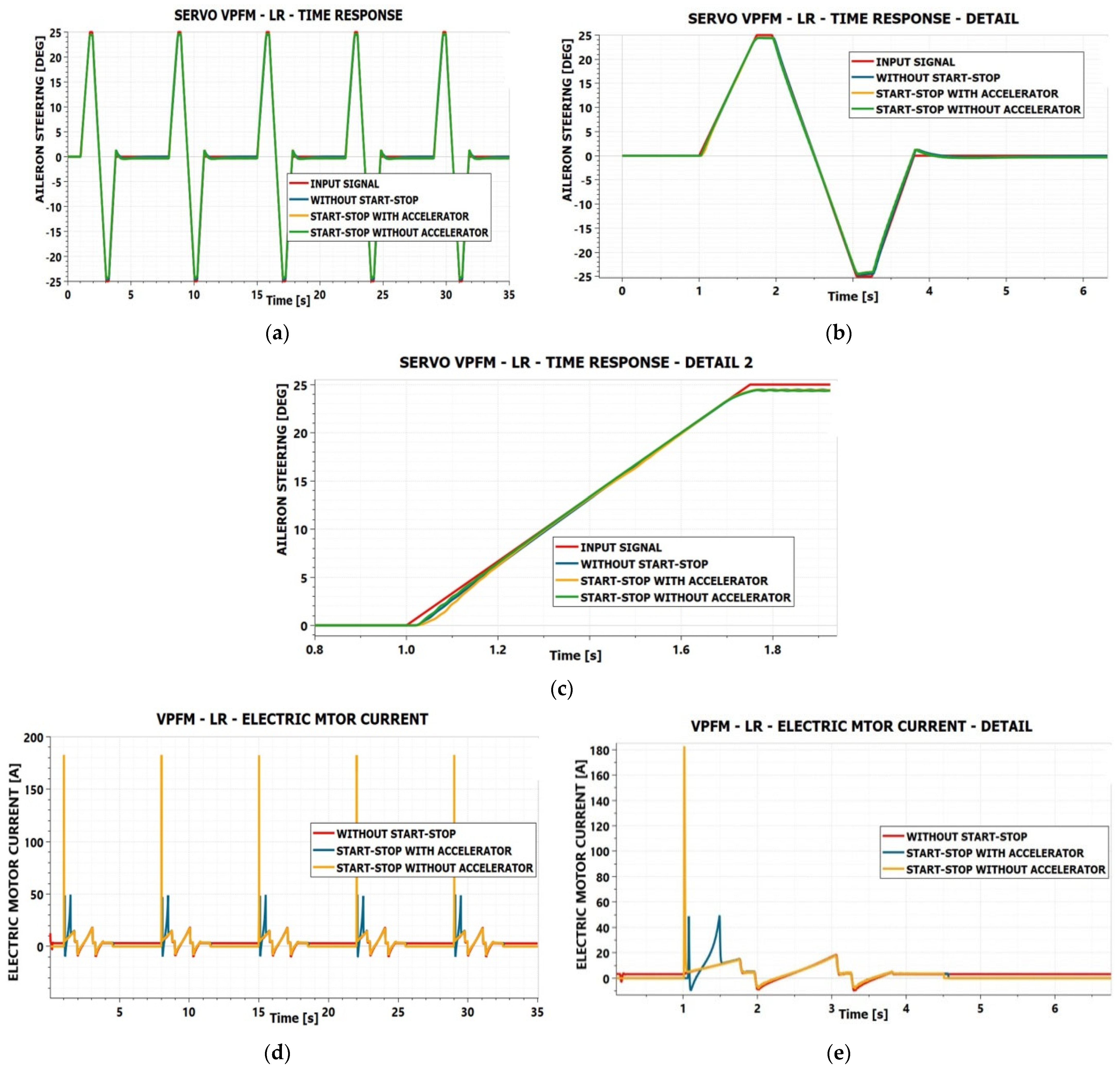
Figure 10c, are also negligible. Consequently, the configuration corresponding to case 1 was selected, and simulations were repeated for the three variants: without a start–stop system, with a start–stop system without an acceleration device, and with a start–stop system with an acceleration device using the selected configuration. The results of these simulations are presented in
Figure 10.
By analyzing the results presented in
Figure 11, it can be observed that they are very similar to those obtained for the VPFM–HR servo-actuator. The differences between the time responses in the cases without start–stop, with start–stop without an acceleration device, and with start–stop with an acceleration device are negligible.
The acceleration device reduces the current peaks during start-up by approximately 3.6 times when the start–stop system is used. The behavior of the main motor speed is similar to that observed in the VPFM–HR case. The power peaks are of the same order of magnitude, and the achieved energy savings are comparable to those obtained for the VPFM–HR configuration.
Therefore, from the overall operational perspective, the VPFM–LR servo-actuator also performs well when the start–stop system with an acceleration device is implemented, benefiting from the advantages of this solution.
However, an important difference appears in the variation in the swashplate angle of the main pump, as shown in
Figure 11. The low transmission ratio mechanism between the auxiliary motor and the pump swashplate transmits strong feedback impulses to the motor, originating from the pump pistons. As a result, significant oscillations of the swashplate angle occur both at load peaks and during the deceleration phase when the main motor is being stopped.
During the shutdown phase of the main motor, the variation in frequency of these piston-induced impulses leads to instability in the operation of the servo-actuator. To mitigate this phenomenon and to ensure a rapid transition through the deceleration phase, it was necessary to introduce a brake on the shaft of the main motor, as shown in
Figure 8.
By comparing
Figure 8f with
Figure 11f, a faster decrease in speed can be observed in the latter case, due to the presence of the brake mounted on the motor shaft.
Due to these vibrations transmitted from the pump swashplate to the auxiliary control motor, this configuration is less advantageous than the VPFM–HR variant, as it may lead to instabilities in the servo-actuator operation.
An alternative solution could be the use of a stepper motor for controlling the swashplate of the main pump, as it provides higher stiffness and is less sensitive to external torques. A more detailed study is required to confirm the feasibility of implementing such a solution.
5. VPFM-Type Servo-Actuator–HYD Configuration with Accelerator
Unlike the VPFM–HR and VPFM–LR servo-actuators, the VPFM–HYD configuration uses an auxiliary hydraulic system to control the swashplate of the main pump. This configuration is also detailed in [
31] and is extended in this paper with a start–stop system with an acceleration device. The simulation scheme for this case is presented in
Figure 12.
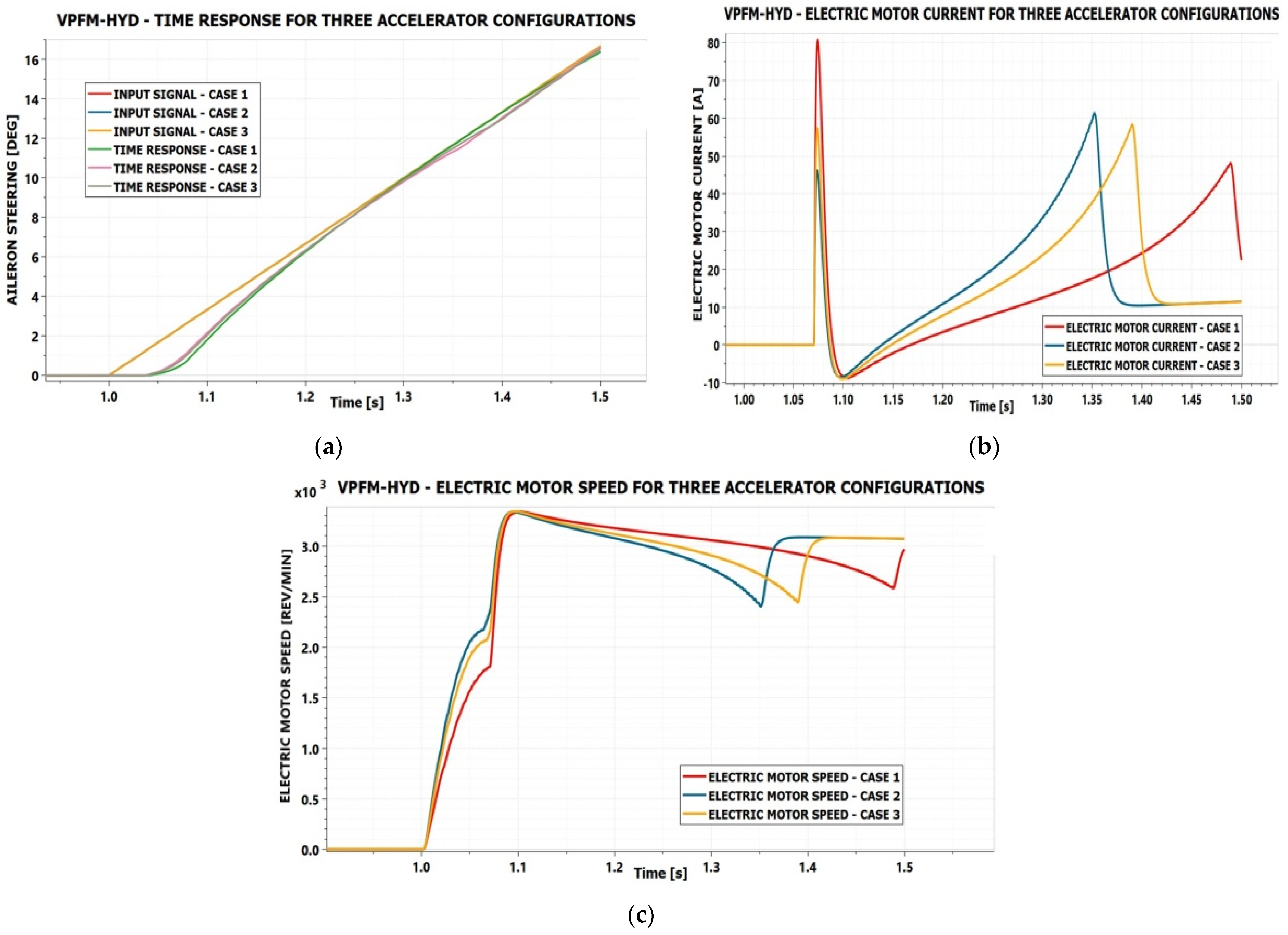
Based on the data obtained in the previous cases, the configurations presented in
Table 3 were selected for testing in order to determine the best configuration of the acceleration system.
The simulation results for the three cases are presented in
Figure 13.
As in the case of the other two analyzed servo-actuators, the differences in the response time are negligible. From the perspective of current peaks, the most suitable configuration corresponds to case 3 in
Table 3. It can be observed that, in this case, a hydraulic machine with a slightly larger displacement is required compared to the previously analyzed servo-actuators.
This can be explained by the fact that the main motor now also drives the pump of the auxiliary hydraulic system used for controlling the swashplate of the main pump, and is therefore subjected to higher loads, requiring higher torque during acceleration. For this reason, an increase in the current peaks can also be observed, from values of 42 and 49 A to 57.5 and, respectively, 59 A.
However, from the point of view of the accumulator volume, maintaining the value at 0.3 L still leads to satisfactory results.
Using the accelerator configuration corresponding to case 3 in
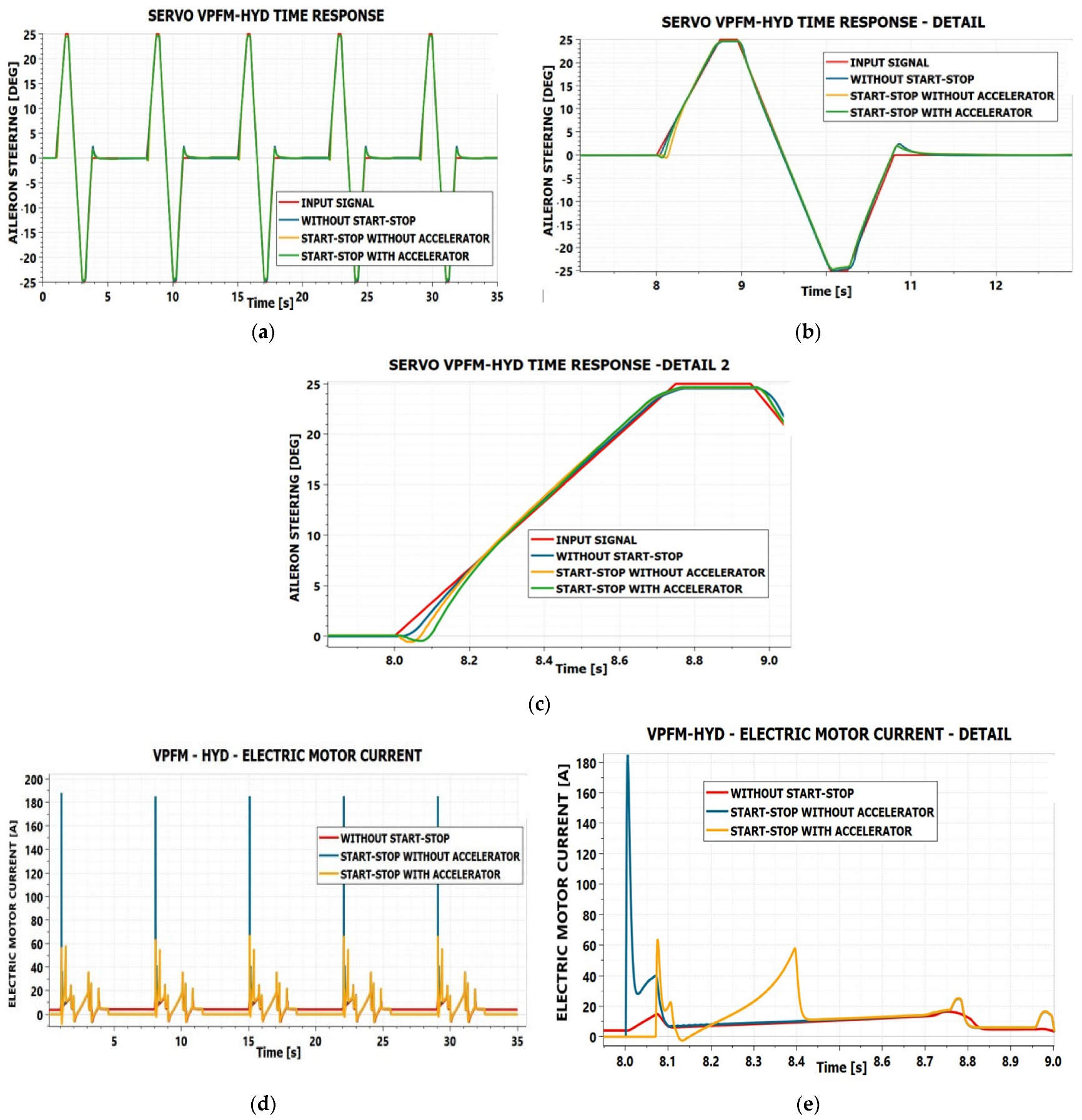
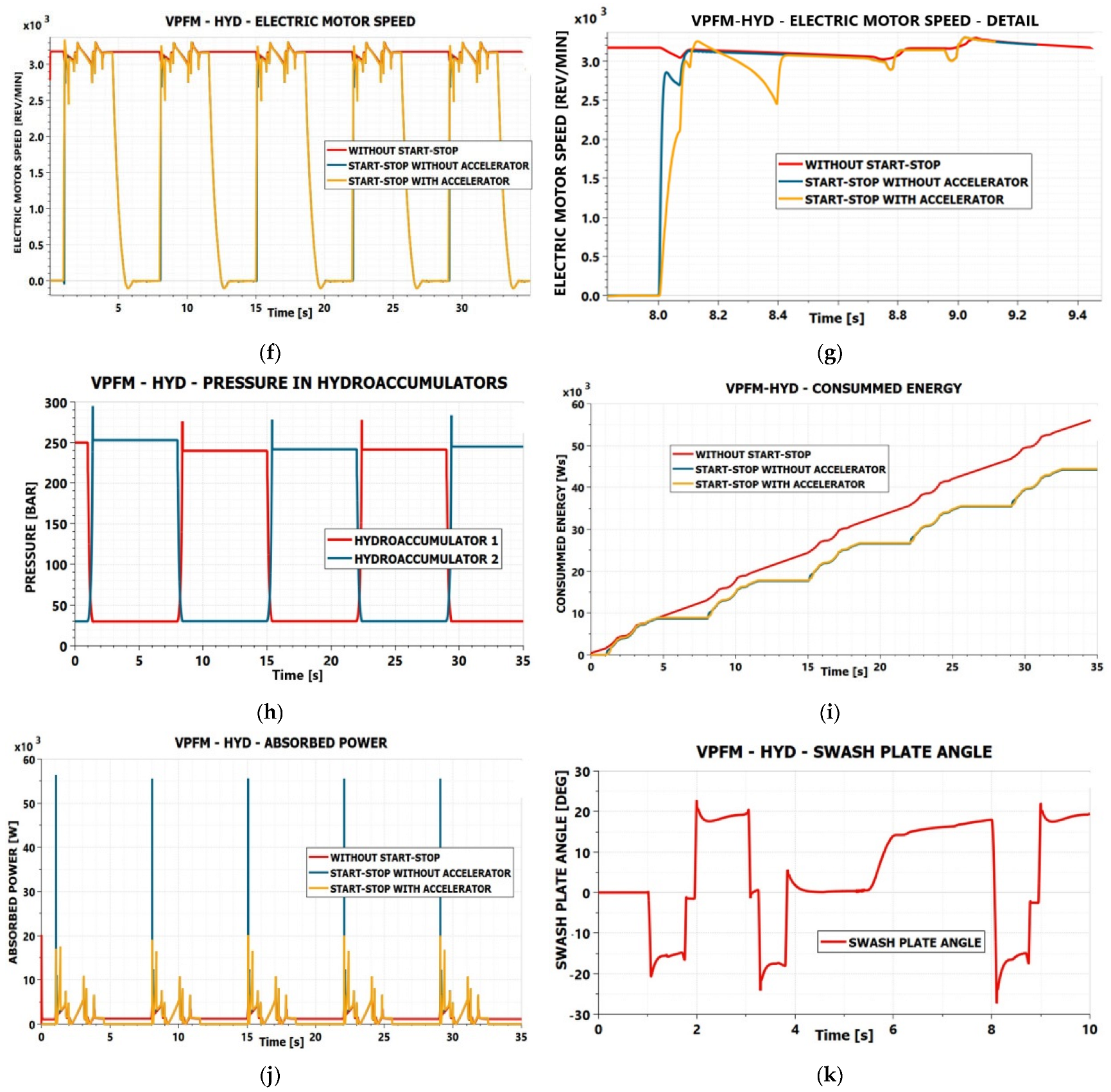
Table 3, simulations were also performed for the VPFM–HYD servo-actuator for the three variants: without start–stop system, with start–stop system without acceleration device, and with start–stop system with acceleration device. The results are presented in
Figure 14.
By analyzing the results presented in
Figure 14, it can be noticed that this servo-actuator also exhibits good performance when the start–stop system with an acceleration device is implemented. The time responses for the configurations without start–stop, with start–stop without an acceleration device, and with start–stop with an acceleration device are nearly identical.
Differences of approximately 2–3 deg occur during the start-up phase over a period of about 0.2 s, after which the behavior becomes practically identical. The acceleration device reduces the start-up current peaks by approximately three times, which is considered sufficient to allow the implementation of the start–stop system.
The pressure variation in the hydraulic accumulators shows proper behavior, ensuring successive start-ups of the servo-actuator. An energy saving of approximately 20% is also observed for the considered test sequence, compared to the case without start–stop.
Regarding the variation in the swashplate angle of the main pump, a favorable behavior is observed, without significant oscillations. This is due to the high stiffness of the hydraulic actuation system of the swashplate.
It can be concluded that the VPFM–HYD configuration presents both advantages and disadvantages compared to the other two variants. It provides more rigid and reliable control of the pump swashplate, and, with further refinement of the automatic control system, an improved servo-actuator response can be achieved. However, it also leads to higher energy consumption, increased system complexity, and consequently higher cost.
We presented in this work three constructive versions of the VPFM EHS with start-stop devices because, in practice, there are many possibilities to implement the same functional principle, but each implementation raises specific difficulties. The VPFM-HR version offers good dynamic response, but needs a worm-gear transmission, which is more expensive. It ensures a smaller energy consumption than the VPFM-HYD.
The VPFM-LR version appears to be quite good, offering similar dynamic performances with the VPFM-HR version, but as was noticed in the simulations, it presents the danger of instability regimes. Variable motor speed leads to force pulses with variable frequency, transmitted from the swashplate to its control system. When the pulse frequency overlaps with the control system eigenfrequencies, the EHS enters unstable regimes. Obviously, this situation is not permitted in the flight control systems. The low rigidity of the transmission from the control motor to the swashplate is responsible for these unstable regimes. It is a question whether a stepper motor that is known to have higher rigidity would be enough to surpass this difficulty. It would be a simpler and cheaper solution, but it has to be proven. It could be the subject of future work or experimental tests that could not be achieved in this work. If enough funds are obtained, it is possible to perform these tests.
The VPFM-HYD version is the most performant from a dynamics point of view in the nominal regime. However, because the electric motor has to drive three hydraulic machines—the swash plate pump, the pump of the secondary hydraulic circuit driving the swashplate, and the accelerator hydraulic machine—the start regime after an idle period is a little bit longer than the VPFM-HR version, and a slightly longer delay appears in the start process. Furthermore, the power absorbed by this version is higher than the power absorbed by the other two versions. For this reason, the start-stop system would be more desirable for this version.
From the weight point of view, a comparison between the presented versions was achieved in [
31]. All the versions presented in this work are improved with the same accelerator device with respect to the versions presented in [
31], so the conclusions will be the same.
6. Conclusions
The use of a start–stop system with an acceleration device for VPFM-type EHS servo-actuators allows a significant reduction in energy consumption, while the time response of the servo-actuator is only minimally affected, and the current peaks during the start-up of the main pump motor are reduced by approximately three times.
This reduction in start-up current peaks results in significantly lower stress on both the electric motor and the power converter, allowing a large number of start cycles without risking overheating or other forms of overloading that could affect the proper operation of the servo-actuator. Considering that FPVM-type servo-actuators impose much higher stress on the electric motor and its control converter, it can be stated that VPFM servo-actuators equipped with a start–stop system and acceleration device represent a promising alternative for aircraft flight control applications.
Concerning the efficiency of the EHS, we can say it has not decayed in a significant manner. The extra energy consumed to charge one hydro-accumulator is recovered at the next start. In the nominal regime, it appears that a small extra power is consumed due to the accelerator gear motor working in zero load conditions, but this energy is much smaller than the energy saved in the idle regime.
The numerical simulations performed in this study demonstrate a good overall behavior of the servo-actuator with start–stop system and acceleration device, confirming the feasibility of implementing such a system in aircraft flight control actuators. The energy savings achieved can be particularly significant during long-duration flights, where in cruise conditions, flight control surfaces are only rarely actuated.
The simulation results show that the time response of the servo-actuator during start-up is only slightly affected and does not compromise the control performance of the aircraft. As an operational option, if the presence of the start–stop system is perceived as undesirable by the pilot during certain flight phases, it can be deactivated. For example, during phases with frequent and large control inputs, such as takeoff and landing, the system can be turned off and reactivated during cruise conditions, when control inputs are minimal.
The reduction in stress on the electric motor and power converter, compared to FPVM servo-actuators, allows a potential decrease in their size and weight. However, this reduction is partially offset by the additional components of the acceleration device—namely, two hydraulic accumulators, a gear-type hydraulic machine, and an electrohydraulic directional valve, together with the associated electronic control system.
Based on the dimensions of the components used in the numerical simulations, the total mass of the acceleration assembly can be estimated at approximately 2.5 kg, assuming a compact design with all components integrated into a single unit. This introduces an additional onboard weight, which translates into increased fuel consumption. A more detailed study is required to determine whether the energy savings achieved by the start–stop system with an acceleration device are offset by the additional fuel consumption due to this weight increase.
As a first approximation, it can be stated that the mass of the servo-actuators represents a very small fraction of the total mass of a commercial aircraft; therefore, the additional fuel consumption associated with the presence of the acceleration system in VPFM servo-actuators is practically negligible, and the energy saving is prevalent.
We have to mention that this is a primary study concerning the idea of using a start-stop device with an accelerator for EHS. The obtained results offer a promising perspective but are not sufficient to define a verdict concerning the value of this idea. Future work will follow to investigate other aspects of the problem, and if enough funds are gained, an experimental laboratory model will be developed.





 ,
,