Article

Generalized High-Order LADRC Tracking Control for VICTS Hollow Annular Direct-Drive Motor Considering Non-Stationary Disturbances

1
Tsinghua Shenzhen International Graduate School, Shenzhen 518055, China
2
Googol Paradox (DG) Intelligent Technology Co., Ltd., Dongguan 523808, China
3
School of Mechanical Engineering and Automation, Wuhan Textile University, Wuhan 430073, China
4
The 29th Research Institute of China Electronics Technology Group Corporation, Chengdu 610036, China
5
School of Transportation and Electrical Engineering, Hunan University of Technology, Zhuzhou 412007, China
*
Author to whom correspondence should be addressed.
Actuators 2026, 15(5), 254; https://doi.org/10.3390/act15050254
Submission received: 12 April 2026 / Revised: 24 April 2026 / Accepted: 27 April 2026 / Published: 1 May 2026
(This article belongs to the Section Aerospace Actuators)

Abstract

This paper proposes a generalized high-order linear active disturbance rejection control (GHO-LADRC) method to suppress non-stationary disturbances in VICTS antenna direct-drive motors during high-dynamic scanning. First, a fourth-order generalized extended state observer is constructed, in which the derivative of the total disturbance is explicitly modeled as an extended state. This configuration enables real-time observation of the disturbance rate of change and suppresses the phase lag inherent in traditional ADRC during rapid disturbance variations through disturbance feedforward compensation. Secondly, drawing on singular perturbation theory and the motor’s dual-time-scale characteristics, this work precisely decouples and explicitly extracts the nonlinear friction and electromagnetic damping terms during the modeling stage. By integrating the extracted electromagnetic damping terms and the disturbance variation rate, an improved model-assisted control law is formulated, enabling active compensation for intense dynamic interference. Theoretical analysis and experimental results demonstrate that the proposed method significantly enhances disturbance rejection capability and satellite communication accuracy. As the first application of GHO-LADRC in the field of direct-drive VICTS antenna control, this work validates its effectiveness in improving system robustness within complex dynamic environments.

1. Introduction

The development of aerospace information integration technology is advancing rapidly. Variable Inclination Continuous Transverse Stub (VICTS) antennas, with their unique direct-drive multi-layer structure, achieve efficient beam scanning through mechanical rotation [1,2,3]. As shown in Figure 1a, the VICTS antenna adopts a multilayer structure, which includes an upper polarization layer, a lower polarization layer, a radiation layer and a feed layer. Its built-in antenna structure is equipped with a large-diameter hollow annular direct-drive motor (HADDM). The layers can move freely to complete satellite tracking and communication work [4]. In order to adapt to future satellite Internet applications, it is required that the maximum speed of each layer movement is not less than 400°/s, the acceleration is not less than 800°/s2, and the working condition requirements of airborne shock and vibration are met [5].
Taking a typical airborne Ka-band 2517 on-the-move (OTM) communication antenna as an example, its receiving antenna has a diameter of 25 inches, the transmitting antenna has a diameter of 17 inches, and the thickness of each layer is about 10 mm. This large-diameter, thin-walled hollow structure is susceptible to the influence of carrier motion and turbulence, which easily triggers low-frequency flexible modes, causing the overall structure to produce elastic waves, as shown in Figure 1b. These mechanical waves propagate along thin-walled structures, causing dynamic changes in local normal forces and relative displacements, resulting in rapidly changing non-stationary disturbances. At the same time, environmental factors such as increased damping during low-temperature operation have a significant impact on the dynamic performance of HADDM, which in turn affects the communication quality of the antenna [6]. Therefore, researching control algorithms with good robustness is a key technology to ensure the quality of satellite communication in high-dynamic environments.
To address the effects of disturbances and uncertainties in the system on permanent magnet motors, researchers have proposed various methods, such as adaptive control [7], H∞ control [8], sliding mode control [9], and model predictive control [10]. Linear active disturbance rejection control (LADRC), with its advantages of not relying on an accurate model of the controlled object and strong robustness, has become one of the important schemes in the field of high-precision servo control [11]. Xu et al., targeting the issues of large observer delay and strong noise caused by periodic disturbances at low motor speeds, proposed an improved LADRC incorporating error proportional feedback and a high-pass filter, achieving enhanced disturbance observation capability and suppression of speed pulsation [12]. Wang et al., to address the single-degree-of-freedom characteristic and insufficient disturbance rejection capability of traditional LADRC, proposed an enhanced LADRC method with a compensation function observer, achieving system decoupling, improved disturbance rejection, and robustness [13]. Wang et al., aiming at the coupling between dynamic response and disturbance rejection in LADRC and its poor suppression of nonlinear disturbances, proposed a two-degree-of-freedom LADRC strategy, achieving decoupling of system performance, enhanced robustness, and simplified parameter tuning [14]. Slimani, to address overshoot and parameter uncertainty in Permanent Magnet Synchronous Motor (PMSM) speed regulation, proposed a finite control set model predictive current control, eliminating speed overshoot, accelerating response speed, and significantly enhancing robustness [15]. Under the existing active disturbance rejection control framework, the traditional linear extended state observer (LESO) is suitable for handling constant or extremely slowly varying disturbances.
However, during actual operation, especially when performing high-dynamic scanning tasks, the nonlinear friction in the HADDM exhibits significant non-stationary characteristics, and its change rate shows clear acceleration features—that is, both the first-order and second-order derivatives of the disturbance are strictly non-zero [16]. The traditional LESO suffers from unavoidable phase lag and limited estimation bandwidth when dealing with such non-stationary disturbances. To address this issue, researchers have conducted extensive studies on observer structure design. Fully decoupled active disturbance rejection control employs a high-order structure to achieve complete decoupling of tracking and disturbance rejection performance, greatly simplifying the parameter tuning process of the motor [17]. Time-delay-aware reduced-order observers, through optimization using intelligent algorithms, effectively compensate for the impact of signal transmission delay on the stability of time-delay systems [18,19]. Furthermore, by embedding a phase compensation link or a repetitive control module into the observer, novel enhanced active disturbance rejection architectures effectively suppress high-frequency measurement noise and periodic current harmonics in motors [20,21]. Nevertheless, when facing disturbances with strongly non-stationary characteristics and strictly non-zero higher-order derivatives in the HADDM, the design of the observer must take into account both wideband disturbance rejection and high-order dynamic evolution prediction.
On the other hand, for non-minimum phase, communication delay, and underactuated characteristics in servo systems, Model-Assisted Active Disturbance Rejection Control (Model-Assisted ADRC) has become a research focus because it can alleviate the burden on the observer by incorporating known model information, allowing the observer to focus on unknown disturbances [22]. Jin K., Korompili, Srikanth and colleagues embedded minimal plant knowledge into the extended state observer design and proposed model-assisted reduced-order ADRC and model-assisted extended observation schemes, respectively, effectively solving the estimation bias problem in disturbance compensation [23,24,25]. Meanwhile, Korompili, Jin C., and others utilized the physical structure information of DC-DC converters to construct a generalized model-assisted ADRC framework. By introducing Kalman filtering and sliding mode observers, they enhanced the physical significance of state estimation, solved the control accuracy problem of non-minimum phase converters under matched and mismatched disturbances, and significantly improved system robustness under extreme operating conditions [26,27]. For the HADDM, fully exploiting the dual-time-scale physical prior information of motor velocity and current to perform refined dynamic decoupling is of positive significance for improving observer performance.
To address the non-stationary disturbances of HADDM, this paper proposes a generalized high-order linear active disturbance rejection control (GHO-LADRC) method. This method constructs a generalized high-order linear extended state observer (GHO-LESO), which explicitly models the second-order derivative of the total disturbance as an extended state, thereby enabling observation of the rate of change in non-stationary disturbances. Through disturbance feedforward, the phase lag caused by rapid disturbance variations is eliminated. On this basis, this paper makes full use of physical prior information and introduces singular perturbation theory (SPT) during the motor modeling stage. Leveraging the dual-time-scale characteristics of HADDM, the nonlinear friction and electromagnetic damping terms are accurately decoupled and explicitly extracted. By integrating the extracted electromagnetic damping terms and the disturbance variation rate, an improved model-assisted control law is synthesized. This law enables active compensation before strong dynamic disturbances exert significant influence, thereby theoretically ensuring good satellite tracking accuracy for the VICTS antenna under highly dynamic scanning conditions.
The main contributions of this paper are as follows: (1) By explicitly modeling and capturing the derivative information of the total disturbance, the inherent phase lag of traditional active disturbance rejection control under non-stationary disturbance conditions is mathematically mitigated. (2) By leveraging the dual-time-scale physical characteristics revealed by singular perturbation theory, this work achieves the precise decoupling of nonlinear friction and electromagnetic damping terms. Through the integration of electromagnetic damping terms and the disturbance variation rate, the robustness boundary of the system under highly dynamic scanning is significantly enhanced. (3) As the first exploration to introduce the GHO-LADRC framework into the field of VICTS antennas control, this paper validates the application effects of the proposed strategy through experiments. The remainder of this paper is organized as follows: Section 2 introduces the dynamic modeling of HADDM; Section 3 presents the design and analysis of the generalized high-order observer for the HADDM; Section 4 describes the design of the improved LADRC for the HADDM based on GHO-LESO and provides the stability proof; Section 5 presents simulation and experimental analysis; Section 6 summarizes the full paper.

2. Dynamic Modeling of HADDM

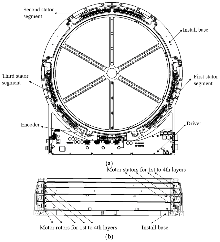
As shown in Figure 2, the HADDM studied in this paper adopts a multi-layer disk structure. Through optimized stator phasing and end treatment, each rotating layer can be equivalently, in terms of torque mechanism, to an independent surface-mounted PMSM, where the rotating parts and integrated windings correspond to the rotor and stator, respectively. After parameter conversion, the dynamic characteristics of each direct-drive mechanism can be fully described by the standard PMSM mathematical model. To achieve high-performance control of the HADDM, the voltage equations in the rotating coordinate system are established as follows [14]:
{ U d = R s i d + L s d i d d t ω e L s i q U q = R s i q + L s d i q d t + ω e ( L s i d + ψ f )
The corresponding motor mechanical motion equation is:
{ J d ω m d t = T e T L B ω m θ ˙ m = ω m T e = 3 2 P n ψ f i q = K t i q
where  U d U q  and  i d i q  are the stator voltage and current components on the  d  and  q axis, respectively;  R s  is the stator resistance,  L s  is the stator inductance,  ψ f  is the permanent magnet flux linkage,  θ m  is the mechanical angle,  ω m  is the mechanical angular velocity,  J  is the moment of inertia,  T e  is the electromagnetic torque,  T L  is the load torque,  B  is the viscous friction coefficient,  P n  is the number of pole pairs, and  K t  is the torque coefficient.  T L  includes not only the mechanical load but also the coupling torque caused by relative rotation between layers and its dynamic variations.
The electromagnetic subsystem of the HADDM responds much faster than the mechanical subsystem, exhibiting a significant dual-time-scale characteristic. By reconstructing the dynamic equations of the HADDM using singular perturbation theory (SPT) [28], the electromagnetic damping term can be separated from the multi-dimensional disturbances, thereby reducing the computational burden on the observer and achieving accurate compensation for time-varying disturbances. The nominal model of the reconstructed second-order system is as follows:
θ ¨ m = ω ˙ m = b 0 i q r e f + f ( ω m ) + d t
where  i q r e f  is the control input, and  b 0 = 3 P n ψ f 2 J  is the nominal control gain.
f ( ω m ) = 3 P n 2 ψ f 2 2 J R s ω m = c 0 ω m  is the explicit electromagnetic damping term caused by the back electromotive force effect, which is the electromagnetic torque generated by the current induced by the back electromotive force. Using this term as known physical prior information for feedforward compensation can significantly reduce the observation burden on the observer.  c 0  is the electromagnetic damping coefficient. Since it characterizes the ratio of torque to angular velocity, its unit is proportional to s−1 d t = B J ω m 1 J T L + Δ ( t )  is the generalized lumped disturbance, which includes unknown friction, non-uniform load, etc. And  Δ ( t )  represents external time-varying disturbances.

3. Design and Analysis of Generalized High-Order Observer for HADDM

3.1. Extended State Space Modeling and Disturbance Description of HADDM

To achieve accurate observation of the full-dimensional non-stationary disturbance acceleration, the state vector is defined as  x = [ x 1 , x 2 , x 3 , x 4 ] T = [ θ m , ω m , d t , d ˙ t ] T , combined with the reconstructed model in Equation (3), the following fourth-order extended state space model is established:
{ x ˙ 1 = x 2 x ˙ 2 = x 3 + b 0 i q r e f + f ( x 2 ) x ˙ 3 = x 4 x ˙ 4 = h ( t )
where  x 4  is the newly added extended state, used to extract the acceleration of the total disturbance  d ˙ t  in real time,  f ( x 2 ) = f ( ω m )  is the explicit electromagnetic damping term, and  h ( t ) = d ¨ t  is the higher-order term of the disturbance.
Assumption 1. 
d ¨ t  is bounded, i.e.,  | h ( t ) | H , where  H = s u p t [ 0 , )   [ | B J ω ¨ m | + | 1 J T ¨ L | + | Δ ¨ ( t ) | ] .

3.2. Construction and Parametric Tuning of Generalized High-Order Observer

To observe the non-uniform disturbance and its derivative in real time, the following fourth-order GHO-LESO is designed:
{ z ˙ 1 = z 2 l 1 ( z 1 x 1 ) z ˙ 2 = z 3 + b 0 i q r e f + f ( z 2 ) l 2 ( z 1 x 1 ) z ˙ 3 = z 4 l 3 ( z 1 x 1 ) z ˙ 4 = l 4 ( z 1 x 1 )
where  z = [ z 1 , z 2 , z 3 , z 4 ] T = [ θ ^ m , ω ^ m , d ^ t , d ˙ ^ t ] T . The gain matrix  L = [ l 1 , l 2 , l 3 , l 4 ] T  is determined using the bandwidth parameterization method,  l 1 = 4 ω 0 l 2 = 6 ω 0 2 l 3 = 4 ω 0 3 l 4 = ω 0 4 , where  ω 0  is the observer bandwidth, which directly determines the sensitivity of the system to capture non-stationary disturbances and their derivatives.

3.3. Proof of Observer Convergence

Define the state observation error vector  e = [ e 1 , e 2 , e 3 , e 4 ] T = x z . Then, from (4) and (5), the differential equation of the observer error can be expanded as follows:
{ e ˙ 1 = e 2 l 1 e 1 e ˙ 2 = e 3 + [ f ( x 2 ) f ( z 2 ) ] l 2 e 1 e ˙ 3 = e 4 l 3 e 1 e ˙ 4 = h ( t ) l 4 e 1
To simplify the equation, (6) can be written in the following matrix form:
e ˙ = A e e + B e h ( t ) + Δ f  
where  A e = [ l 1 1 0 0 l 2 0 1 0 l 3 0 0 1 l 4 0 0 0 ] . All eigenvalues of matrix  A e  are placed in the left half-plane, so  A e  is a strictly Hurwitz matrix.  B e = [ 0,0 , 0,1 ] T , and the residual of the electromagnetic damping term is  Δ f = [ 0 , f ( x 2 ) f ( z 2 ) , 0,0 ] T .
Theorem 1. 
For the observation error dynamics described by Equation (7), if the disturbance acceleration satisfies   | h ( t ) | H , and the observer bandwidth  ω o  is chosen sufficiently large such that the convergence factor  η = λ m i n ( Q e ) 2 L f λ m a x ( P e ) > 0 , then the state observation error vector  e  is uniformly ultimately bounded. The steady-state observation accuracy is jointly determined by the upper bound  H  of the disturbance acceleration and the observer bandwidth  ω o .
Choose the positive definite quadratic function  V o = e T P e e , where  P e  is the unique positive definite solution matrix satisfying the Lyapunov equation  A e T P e + P e A e = Q e , and  Q e  is a preselected positive definite matrix.
Taking the derivative of  V o :
V ˙ o = e ˙ T P e e + e T P e e ˙
Substituting (7) into (8) yields:
V ˙ o = ( A e e + B e h ( t ) + Δ f ) T P e e + e T P e ( A e e + B e h ( t ) + Δ f ) = e T ( A e T P e + P e A e ) e + 2 e T P e B e h ( t ) + 2 e T P e Δ f = e T Q e e + 2 e T P e B e h ( t ) + 2 e T P e Δ f
According to the properties of quadratic forms:
e T Q e e λ m i n ( Q e ) e 2
According to the Cauchy–Schwarz inequality:
2 e T P e B e h ( t ) 2 e P e B e H = 2 λ m a x ( P e ) H e
Considering that the electromagnetic damping term  f ( x 2 )  is a linear function of the rotational speed  x 2 , its slope is determined only by the nominal parameters of the motor. Therefore, within the normal operating range of the HADDM,  f ( x 2 )  satisfies the Lipschitz continuity condition with respect to the state estimation error  e 2 ; that is, there exists a Lipschitz constant  L f > 0 , such that  | f ( x 2 ) f ( z 2 ) | L f | e 2 |  holds. Hence:
2 e T P e Δ f 2 e λ m a x ( P e ) Δ f 2 L f λ m a x ( P e ) e 2
Substituting (10)–(12) into (9):
V ˙ o λ m i n ( Q e ) e 2 + 2 L f λ m a x ( P e ) e 2 + 2 λ m a x ( P e ) H e
Define the convergence factor  η = λ m i n ( Q e ) 2 L f λ m a x ( P e ) :
V ˙ o η e 2 + 2 λ m a x ( P e ) H e
According to Young’s inequality  a b ε 2 a 2 + 1 2 ε b 2 , let  ε = 1 a = e b = 2 λ m a x ( P e ) H :
2 λ m a x ( P e ) H e γ e 2 + ( λ m a x ( P e ) H ) 2 γ
where  γ  is an adjustable positive coefficient. If the bandwidth  ω o  is chosen to be sufficiently large such that  η > γ , then:
V ˙ o ( η γ ) e 2 + ( λ m a x ( P e ) H ) 2 γ
In summary, when the error norm satisfies  e > ( λ m a x ( P e ) H ) 2 γ ( η γ ) V ˙ o < 0 , and the observation error  e  is uniformly ultimately bounded. Thus, Theorem 1 is proved. Since  η  in the denominator grows with a high order as the observer bandwidth  ω o  increases, this provides a theoretical basis for achieving high-precision observation by increasing the bandwidth.

4. Design and Stability Proof of Improved LADRC for HADDM Based on GHO-LESO

4.1. Design of Model-Assisted Control Law Incorporating Physical Priors

To achieve high-precision pointing of the antenna, the disturbance state and its evolution trend captured in real time by the GHO-LESO, together with the physical terms decoupled by SPT, are utilized to design the following improved control law:
Define the system tracking error vector  ε = [ ε 1 , ε 2 ] T , where:
{ ε 1 = θ m θ r ε 2 = ω m ω r
where  θ r  is the reference position command, and  ω r = θ ˙ r  is the reference velocity.
To obtain accurate physical prior information of the controlled plant, this paper first performs frequency-domain identification of the nominal parameters of the HADDM using the least squares method. The observed control gain  b 0  and electromagnetic damping coefficient are directly used to initialize the controller and observer, which significantly alleviates the estimation burden of the GHO-LESO for static uncertainties. Based on the identified nominal model, the current control command  i q r e f  is designed as follows:
i q r e f = 1 b 0 [ k p ε 1 k d ε 2 z 3 f ( x 2 ) + ω ˙ r ]
where:
k p ε 1 k d ε 2  is the proportional-derivative feedback term;
z 3  is the observer-based real-time compensation term for the total disturbance;
f ( x 2 )  is the physical-prior-based electromagnetic damping cancelation term;
ω ˙ r  is the acceleration feedforward term, used to reduce dynamic tracking lag.

4.2. Global Stability and Robustness Analysis of the Closed-Loop Control System

In this section, the overall system stability under the coupling of the controller and the observer is proved by constructing a composite Lyapunov function.
Theorem 2. 
Consider the HADDM closed-loop control system consisting of the extended model in Equation (4), the GHO-LESO in Equation (7), and the improved LADRC in Equation (18). Under the premise that Theorem 1 holds, if suitable control gains   k p ,   k d  are chosen such that the matrix  A c  is strictly Hurwitz, then the composite system consisting of the system tracking error vector  ε  and the observation error vector  e  is uniformly ultimately bounded.
Closed-loop error dynamics description:
Substituting the control law (18) into the system dynamics Equation (4) yields the closed-loop tracking error equation:
ε . = A c ε + B c e 3
where the system matrix  A c = [ 0 1 k p k d ] . By selecting appropriate gains and  k d A c  can be made a strictly Hurwitz matrix.
The disturbance input matrix  B c = [ 0,1 ] T .
The residual disturbance error  e 3 = d t z 3  satisfies  | e 3 | | e .
Select the global Lyapunov function  V :
V = ε T P c ε + σ V o
where  P c  is the positive definite solution matrix satisfying the controller Lyapunov equation  A c T P c + P c A c = Q c , and  σ > 0  is the adjustment weight coefficient.
Differentiating (20) and substituting into the error Equation (19):
V ˙ = ε T ( A c T P c + P c A c ) ε + 2 ε T P c B c e 3 + σ V ˙ o
According to the Cauchy–Schwarz inequality and  | e 3 | | e :
V ˙ c λ m i n ( Q c ) ε 2 + 2 λ m a x ( P c ) ε e
Substituting (14) into (22):
V ˙ λ m i n ( Q c ) ε 2 + 2 λ m a x ( P c ) ε e σ η e 2 + 2 σ λ m a x ( P e ) H e
Define the composite error norm vector  Ω = [ ε , e ] T . Then the first three terms in (23) can be written in the following standard matrix form:
λ m i n ( Q c ) ε 2 + 2 λ m a x ( P c ) ε e σ η e 2 = [ ε , e ] [ λ m i n ( Q c ) λ m a x ( P c ) λ m a x ( P c ) σ η ] [ ε e ] = Ω T M Ω
where the composite system matrix  M  is defined as:
M = [ λ m i n ( Q c ) λ m a x ( P c ) λ m a x ( P c ) σ η ]
To ensure system stability,  M  should be a positive definite matrix, and then  Ω T M Ω < 0 . Therefore, according to the positive definiteness criterion for matrices, the value of the weight coefficient  σ  must satisfy  det ( M ) > 0 , i.e., choose  σ  such that:
σ > λ m a x 2 ( P c ) η λ m i n ( Q c )
From the matrix property  Ω T M Ω λ m i n ( M ) Ω 2 , Equation (23) can be written as:
V ˙ Ω ( λ m i n ( M ) Ω 2 σ λ m a x ( P e ) H )
Thus, it can be seen that when the system error norm satisfies the following condition,  V ˙ < 0
Ω > 2 σ λ m a x ( P e ) H λ m i n ( M ) = R
From the above derivation, it can be seen that the system error vector  Ω  will eventually converge into a compact set of radii  R ; i.e., the closed-loop system is uniformly ultimately bounded. Since the convergence radius  R  decreases as the observer bandwidth  ω o  increases, Theorem 2 is proved. This provides a complete theoretical guarantee for the HADDM to achieve high-precision control performance under complex operating conditions.

5. Analysis of Simulation and Experimental Results

5.1. Simulation Analysis

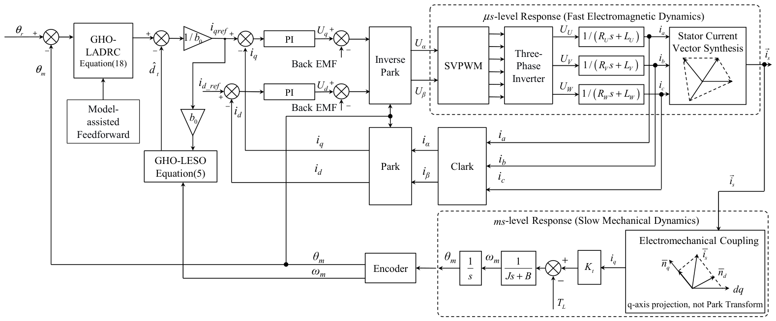
In this section, the effectiveness of the controller is verified through simulation. Figure 3 shows the simulation block diagram of the proposed method. The parameters of the motor are listed in Table 1.
In this simulation diagram, the current loop includes vector transformation. In practical engineering, the bandwidth of the current loop is usually several thousand hertz. By contrast, the highlight block of this figure is the mechanical response, whose actual bandwidth is only tens to hundreds of hertz. For this reason, most engineers simplify the current loop to 1 in simulation modeling. In practical engineering applications, the friction damping coefficient B is a highly uncertain parameter. Therefore, as shown in Equation (3), it is treated as a lumped generalized disturbance together with external disturbances.
The desired position is  θ r = sin ( π t ) rad . Combined with the generation mechanism of time-varying disturbances in the HADDM, three types of disturbance torque are designed:
d ( t ) { 20 + 50 sin ( 20 π t ) rad / s 2 0 t < 1.5 80 rad / s 2 1.5 t < 3.0 80 + 500 ( t 3.0 ) rad / s 2 t 3.0 ,   The   unit   is   rad/s 2 .
In the simulation, the GHO-LADRC algorithm proposed in this paper adopts the observer given by (5) and the controller given by (18). The comparison algorithms are PID and LADRC. To ensure fairness, the controller of LADRC is kept consistent with the controller designed in this paper, i.e.,  i q r e f = 1 b 0 [ k p ε 1 k d ε 2 z 3 f ( x 2 ) + ω ˙ r ] , and the same controller bandwidth  ω c  and observer bandwidth  ω o  are set. The difference is that the LESO in LADRC is of third order, observing only  d t , but not  d ˙ t .
Parameter design principle: To ensure that the convergence speed of the observer is faster than the response speed of the controller, the gain matrix  L  is designed by placing all observer poles at  ω c . To achieve the desired dynamic response of the closed-loop system, the controller gains  k p  and  k d  are tuned using the bandwidth parameterization method, placing the closed-loop poles at  ω c , i.e.,  k p = ω c 2 k d = 2 ω c . The parameters of the PID algorithm are repeatedly tuned to achieve its optimal control performance. The parameters of the observer and controller are shown in Table 1.
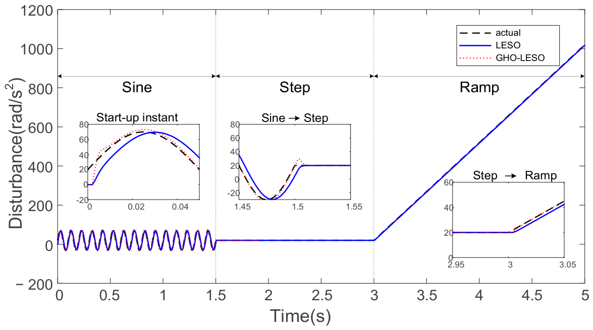
As shown in Figure 4, the observer’s capability to observe the composite disturbance throughout the entire process is demonstrated. Both GHO and LADRC can achieve observation of three types of disturbances. The first partial enlargement shows that the convergence time of GHO is 0.01 s, indicating that GHO has good observation performance for high-frequency time-varying disturbances, while the observed values of LESO exhibit a significant phase deviation. The second partial enlargement shows that when the sinusoidal high-frequency disturbance switches to a step disturbance, the observed value curve of GHO exhibits a spike phenomenon, which results from the GHO observer’s ability to observe the differential term of the disturbance. The third partial enlargement shows that GHO can quickly track a ramp disturbance, whereas LESO has a significant steady-state observation error for the ramp disturbance.
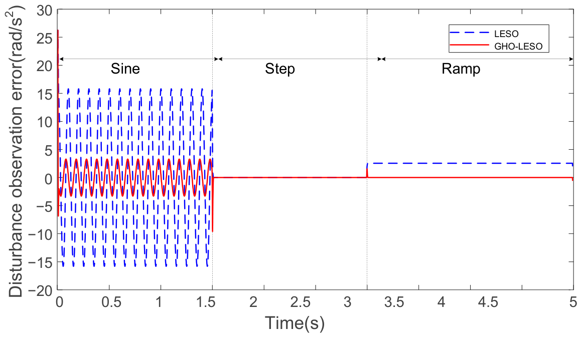
Figure 5 compares the observation errors of the two observers. Under sinusoidal disturbance, the steady-state amplitude of LESO is approximately 15 rad/s2, while that of GHO is approximately 4 rad/s2. In the steady-state phase of step disturbance, both observers achieve good tracking. In the steady-state phase of ramp disturbance, the LESO exhibits a significant observation error with an amplitude of approximately 2.5 rad/s2. The reason is that as long as the derivative of the disturbance is non-zero, the LESO has a constant steady-state error proportional to the slope and inversely proportional to the bandwidth, whereas GHO compensates for this shortcoming by observing the derivative of the disturbance. This result confirms the theoretical prediction of uniform ultimate boundedness of the error in Theorem 1.
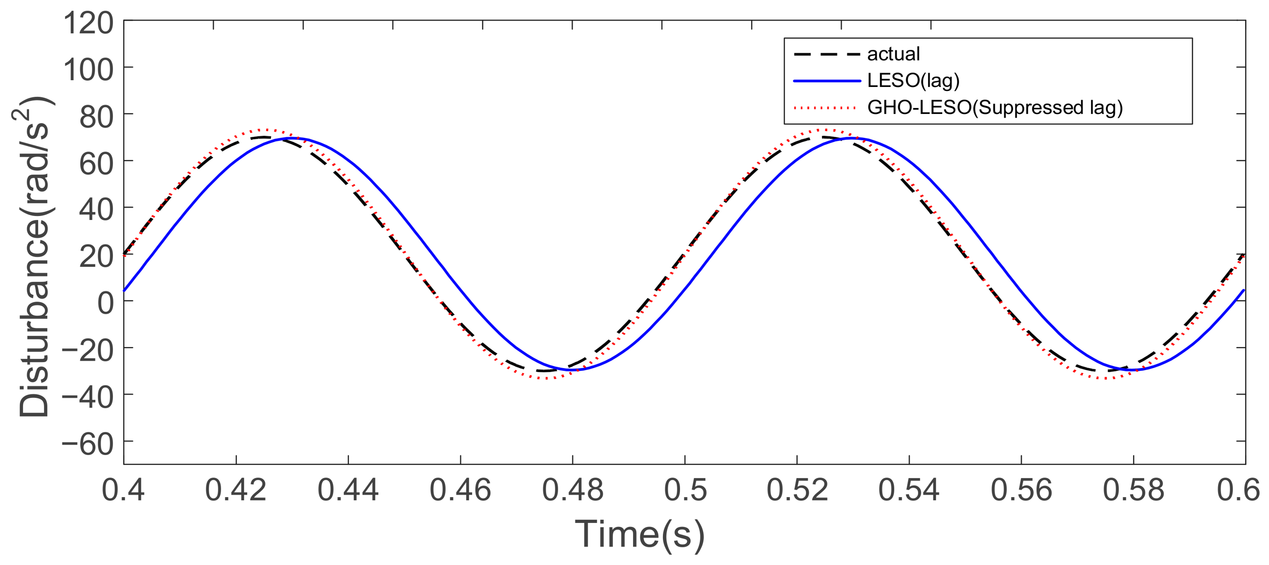
Figure 6 demonstrates GHO’s accurate tracking of the phase of a high-frequency sinusoidal disturbance. The LESO corrects its estimate based on the current measurement error, resulting in an unavoidable lag for time-varying errors, approximately 5–8 ms. By observing the derivative of the disturbance, GHO reduces the phase lag of the observer and achieves accurate observation of fast time-varying disturbances, laying the foundation for improving the accuracy of the controller.
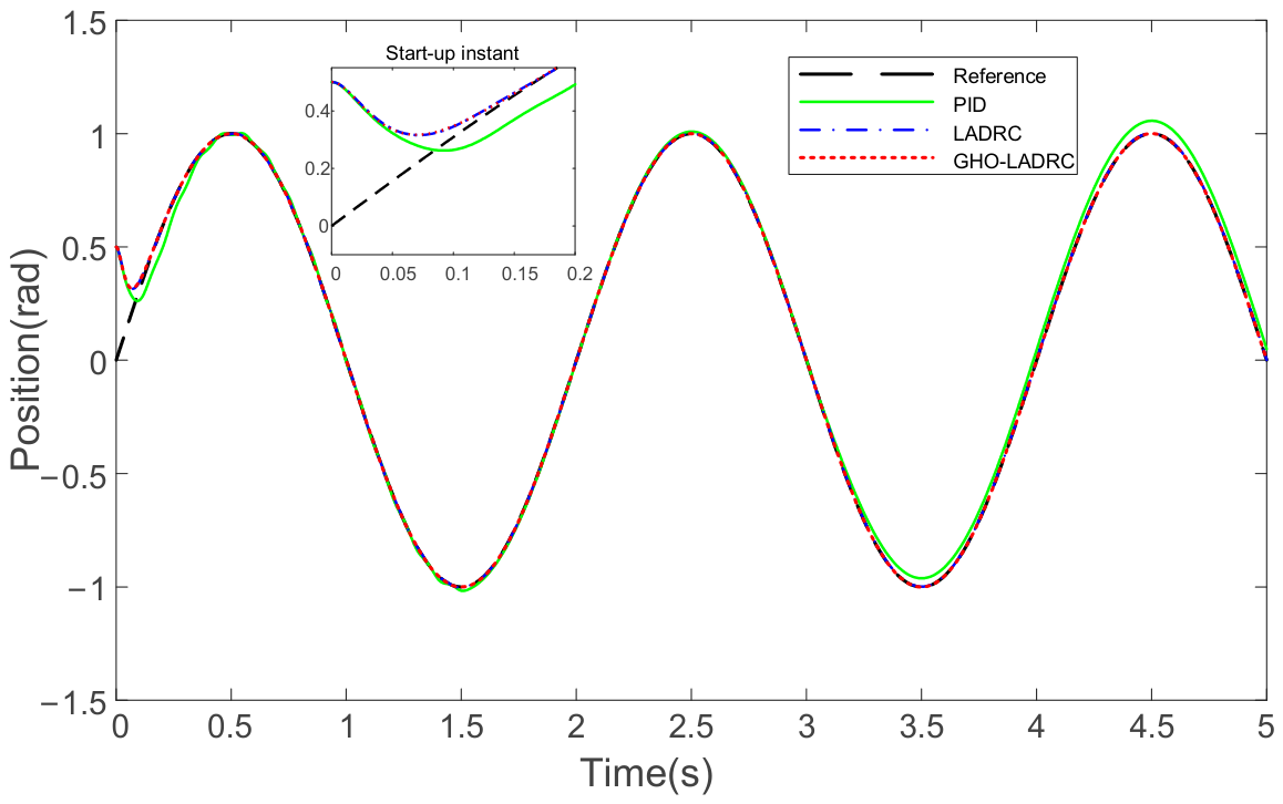
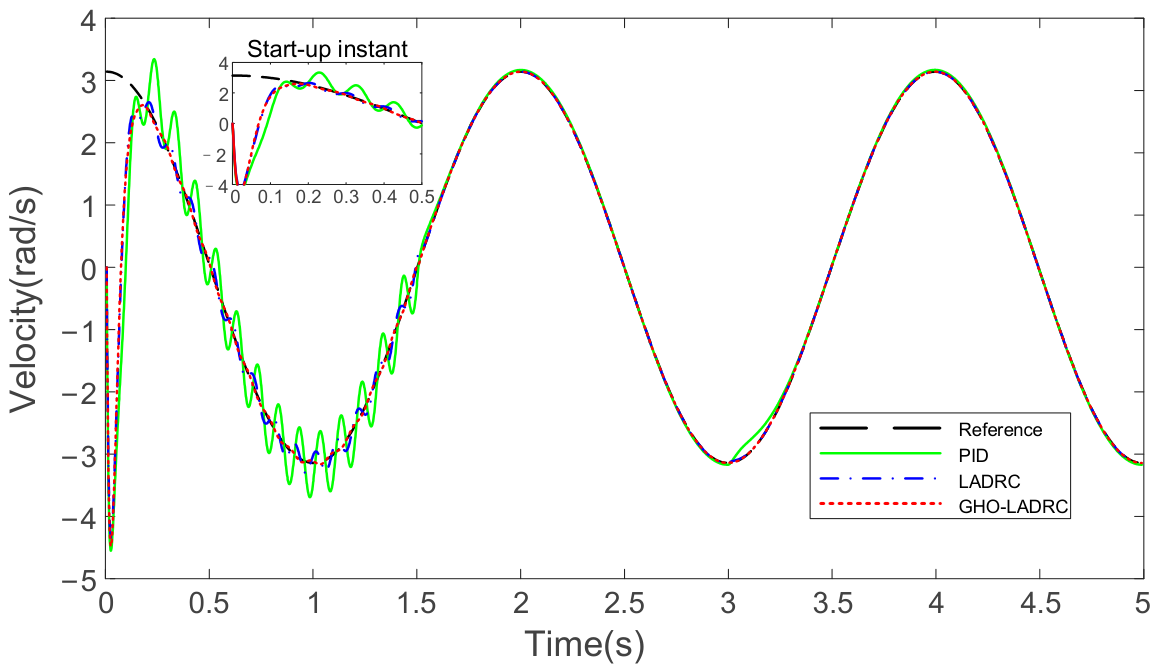
Based on the analysis of observer performance, the position control performance of the GHO-LADRC designed in this paper is further evaluated. Figure 7 shows the tracking performance of different algorithms for a sinusoidal command. The amplitude of the sinusoidal signal is 1 rad. For a fair comparison of tracking performance, the initial positions of all algorithms are set to 0.5 rad, while the initial value of the desired command is 0. From the trajectories, all three algorithms can constrain the actual position of the HADDM to track the desired position, but there are significant differences in convergence speed and steady-state error.
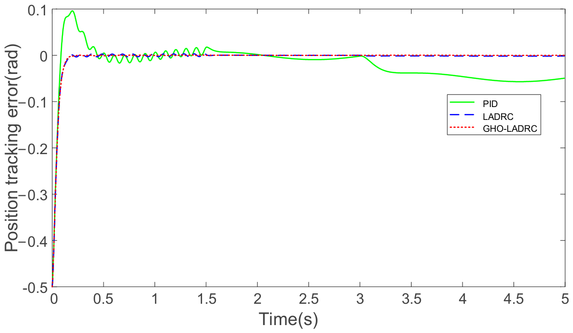
The performance of the controllers can be further compared through the position tracking error plot in Figure 8. PID exhibits an overshoot of approximately 0.1 rad at the initial stage, while LADRC and the proposed GHO-LADRC achieve fast convergence by virtue of disturbance observation and feedforward compensation. Under the action of the three types of disturbances, the steady-state error amplitude of PID is about 0.5 rad, that of LADRC is about 2.8 × 10⁻³ rad, and that of GHO-LADRC is about 0.5 × 10⁻³ rad. This fully demonstrates that the real-time observation of the derivative of time-varying disturbances by the generalized high-order observer plays a crucial role in eliminating dynamic steady-state errors in the HADDM system. The data strongly support the conclusion of uniform ultimate boundedness of the system in Theorem 2.
Figure 9 illustrates the tracking performance of the system for the desired velocity signal under composite disturbances. It can be seen from the figure that when dealing with sinusoidal disturbances, the PID method has a convergence time of approximately 0.25 s, and the velocity curve exhibits significant continuous oscillations with a fluctuation amplitude of about ±0.5 rad/s. Both LADRC and the proposed GHO-LADRC achieve a convergence time of approximately 0.15 s. In particular, the GHO-LADRC method shows no obvious overshoot and maintains high smoothness throughout the entire operation period, indicating that GHO-LADRC can suppress transient shocks caused by abrupt disturbance changes earlier, thereby ensuring robust operation of the system’s velocity loop.
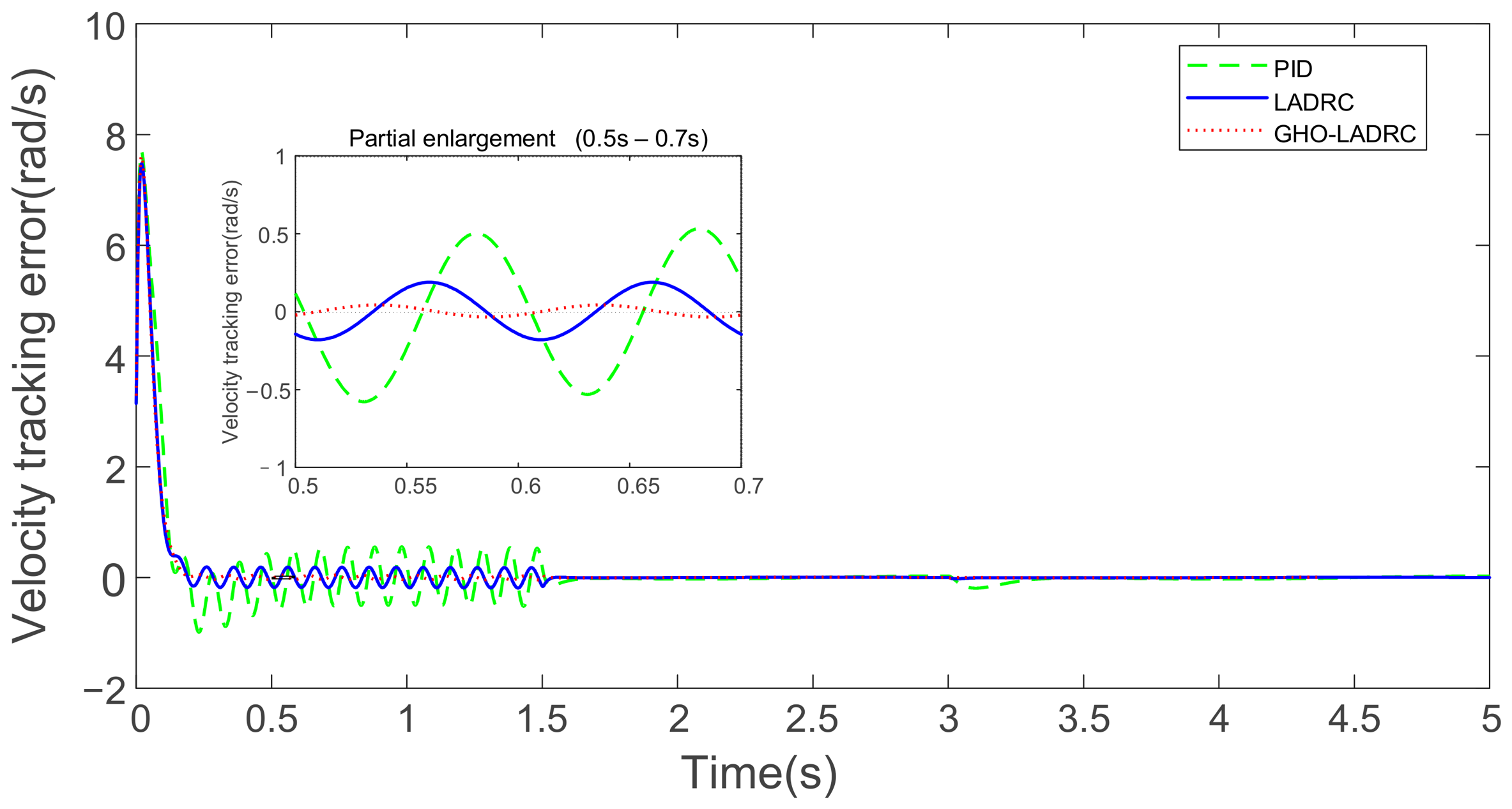
Figure 10 presents a partial enlargement showing the microscopic characteristics of the velocity tracking error. During the high-frequency disturbance test segment from 0.5 s to 0.7 s, the periodic error of LADRC is approximately 0.18 rad/s, while GHO-LADRC successfully limits this error to within 0.02 rad/s, achieving an accuracy improvement of up to 88.9%. In the ramp disturbance phase after 3.0 s, the conventional PID produces an error of about −0.4 rad/s, whereas the tracking error of GHO-LADRC remains consistently near zero. This fully verifies that the generalized high-order observer accurately estimates non-stationary disturbances and their derivatives, significantly enhancing the velocity regulation accuracy of the system under time-varying conditions.

5.2. Experimental Results

5.2.1. Experimental Verification of Motion Performance and Disturbance Rejection Capability of HADDM

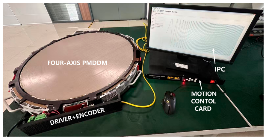
The HADDM device used in the experiment is a self-developed Ku-band receiving antenna motor with an equivalent aperture of 0.6 m. It specifically includes a permanent magnet direct-drive motor, a driver, an encoder, a Googol Technology GSN control card, and host computer software, as shown in Figure 11. The device internally contains four layers of annular permanent magnet direct-drive motors, which are coupled together using integrated thin-walled rolling bearings. Without loss of generality, the second-layer motor is selected as the test object.
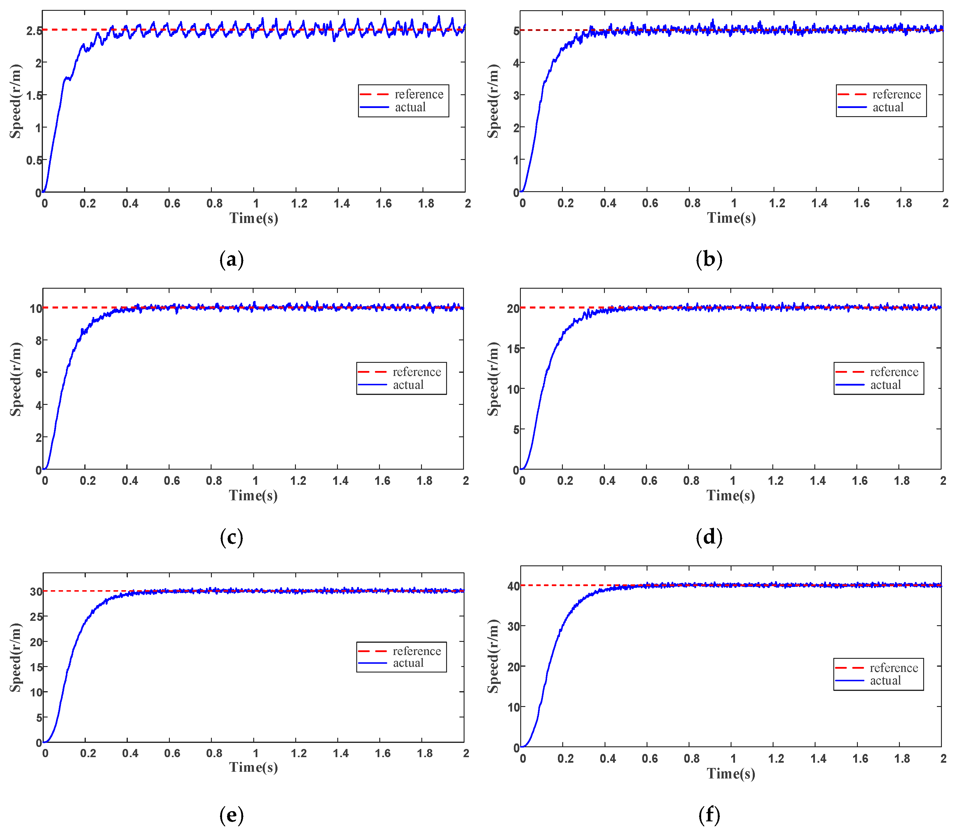
Case 1: The first-, third-, and fourth-layer motors are all powered off. In this case, the motion of the second-layer motor must overcome the random disturbances introduced by the first- and third-layer motors. The maximum design speed of each layer motor of the antenna is 40 rpm. In the experiment, the desired motor speed signal is set as a step signal with amplitudes of 2.5, 5, 10, 20, 30, and 40 rpm, respectively, to verify the dynamic performance of the proposed control method under low-speed, medium-speed, and high-speed conditions. Among these, 5 rpm is the typical speed for system homing and steady-state satellite signal tracking, and 30 rpm is the typical speed for antenna satellite signal tracking and attitude adjustment during vehicle motion and bumpy conditions.
Figure 12 shows the step response of the motor speed at different commanded speeds. It can be observed from the figure that under the proposed controller, the system exhibits good fast response capability at all speeds, with a rapid and smooth dynamic adjustment process. Specifically: (1) At the low speed of 2.5 rpm, friction between the motor and adjacent motors accounts for a large proportion of disturbances, resulting in slower regulation; in the medium-to-high speed range of 20–40 rpm, the system demonstrates good dynamic response, converging within approximately 0.4 s. (2) The speed curves at all speeds exhibit an underdamped behavior with no significant overshoot, indicating that the system parameters are properly tuned and the algorithm has good robustness, avoiding large oscillations. (3) Under different operating conditions, the speed exhibits a certain amplitude of high-frequency pulsation. From the average value perspective, the steady-state error is nearly zero, indicating that the controller has good integral action, ensuring smooth system operation.
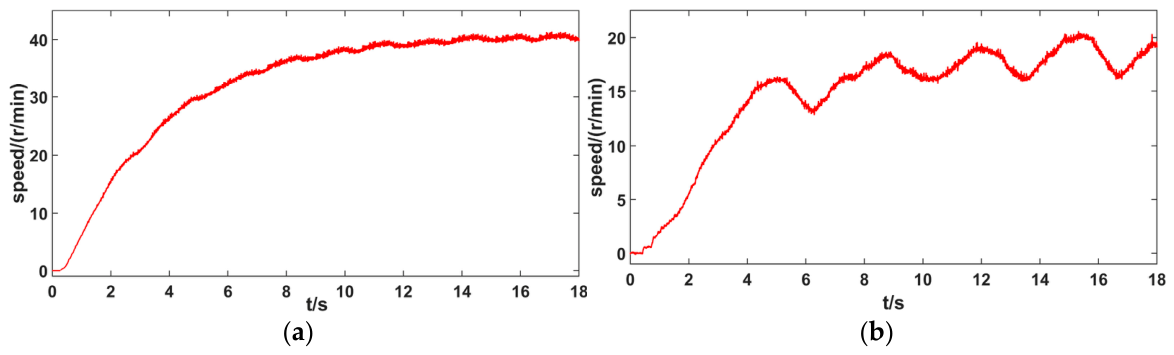
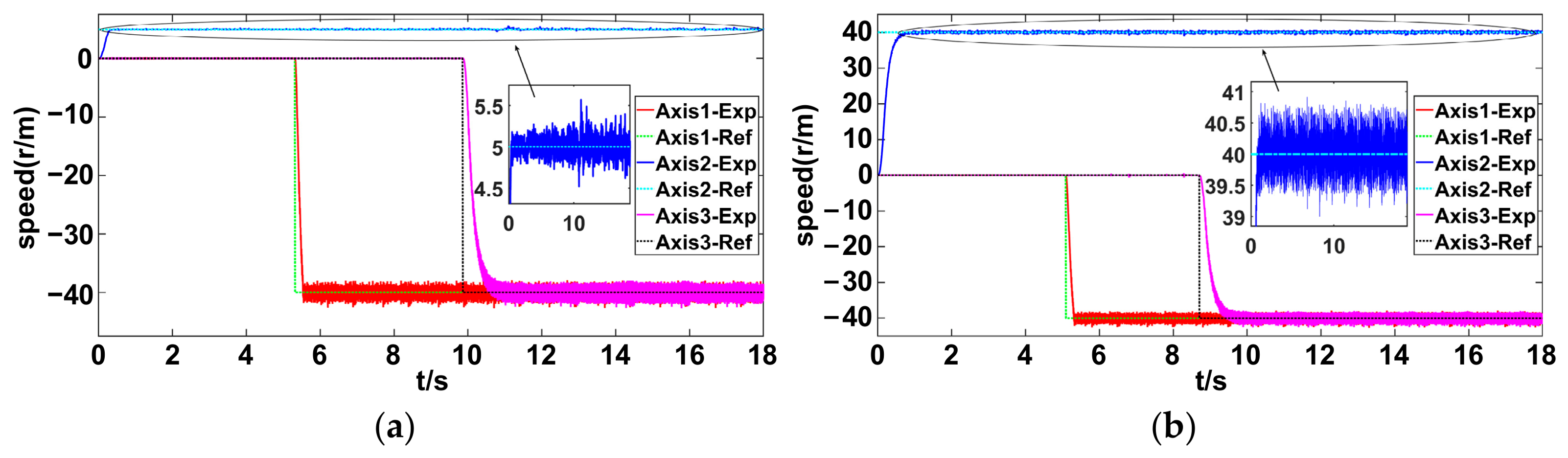
Case 2: Considering that in the actual operation, the disturbance on each layer motor of the antenna mainly comes from the random motion of adjacent motors; to further verify the disturbance rejection capability of the proposed method, the second-layer motor is still taken as the test object. Meanwhile, the first- and third-layer motors are powered on and both run in reverse at the maximum design speed of 40 rpm, generating significant dynamic disturbances that affect the second-layer motor. The main cause of these disturbances is that the geometric errors such as flatness and roundness of the mechanical transmission led to large and varying random resistance when adjacent motors rotate, and the thin-walled bearings undergo unavoidable deformation modes during motion. Under this operating condition, open-loop speed experiments and closed-loop speed experiments are conducted. The commanded speeds for the closed-loop experiments are 5 rpm and 40 rpm.
As shown in Figure 13, in the open-loop speed experiment, the presence of disturbances significantly interferes with the speed response of the tested motor. As shown in Figure 14, in the closed-loop speed experiment, under the action of the controller, the second-layer motor exhibits fast convergence capability at both low and high speeds. Even under disturbances caused by the reverse rotation of the first- and third-layer motors, it still maintains good speed tracking performance. Experiments show that the proposed algorithm possesses good disturbance rejection capability.
With identical experimental conditions and procedures, the comparative experimental results of PID, LADRC and the proposed GHO-LADRC are presented in Table 2. It is verified that the proposed GHO-LADRC achieves superior transient response and disturbance rejection performance compared with conventional LADRC under variable speed conditions. In fact, experiments were carried out on each layer of the motor, and consistent results were observed.

5.2.2. Experimental Verification of Antenna Communication Capability Under Carrier Disturbance

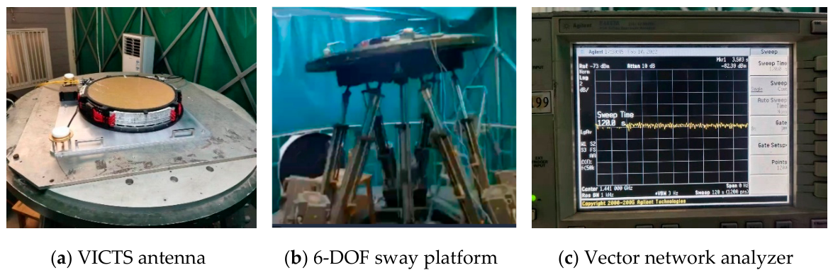
To further verify the effectiveness of the proposed method, based on the motion performance experiments of the HADDM, experiments on antenna communication capability under carrier disturbance are carried out. In the experiments, the VICTS antenna is placed on a parallel six-degree-of-freedom (6-DOF) sway platform. The platform motion is used to simulate the disturbance on the VICTS antenna caused by carrier motion. Meanwhile, the VICTS antenna is connected to the APSTAR-6D satellite to test the antenna’s communication performance under carrier disturbance. The experimental setup is shown in Figure 15. Figure 15a,b show the tested VICTS antenna and the parallel 6-DOF sway platform, respectively. Figure 15c shows the vector network analyzer, which is used to display the attenuation strength of the satellite signal received by the antenna.
In the tests, three categories and six different carrier motion states were set. According to the principle of the VICTS antenna, pitch motion has a significant impact on communication performance, so three different pitch motions were included. Table 3 shows the root mean square (RMS) of the signal strength attenuation of the satellite signal. The comparison algorithm is the conventional PID method used on the same antennas. Under azimuth deflection conditions, the signal strength attenuation of the two methods is consistent. Under roll conditions, the RMS of signal strength attenuation of the GHO-LADRC method is <0.5 dB, which is a 50% reduction in signal attenuation compared to the PID method. Under the three pitch conditions, the RMS of signal strength attenuation of the GHO-LADRC method is <1.0 dB, which is a 60% reduction in signal attenuation compared to the PID method.

6. Conclusions

This paper proposes a GHO-LADRC method to address the non-stationary disturbance problem of the VICTS antenna’s hollow annular direct-drive motor under highly dynamic scanning conditions. To eliminate the phase lag induced by time-varying disturbances, a high-order state observer is constructed, and its stability is theoretically proven. Furthermore, by integrating singular perturbation theory and exploiting the dual-time-scale characteristics of the HADDM, the nonlinear friction and electromagnetic damping terms are accurately decoupled and explicitly extracted. Then, the closed-loop control law is derived, and its stability is verified theoretically, enabling active compensation for intense dynamic disturbances. Experimental results show that the proposed method significantly enhances the system’s disturbance rejection capability. Compared with conventional LADRC, the proposed method improves the transient response under speed changes and suppresses disturbed speed fluctuations by over 20%, with zero overshoot. And satellite communication accuracy under dynamic scanning conditions is significantly improved.
The research findings provide an important guarantee for the airborne application of VICTS antennas to maintain stable communication performance against aircraft attitude changes and turbulence caused by harsh weather conditions. However, restricted by objective conditions, the experiments in this paper have not been carried out under airborne vibration environments. In future work, we will conduct long-distance vehicle road tests with the antenna prototype to verify communication stability under diverse operating conditions, so as to accumulate sufficient experimental data for subsequent airborne applications.

Author Contributions

X.Y.: Conceptualization, methodology, formal analysis and project administration; J.L.: methodology, data curation, and writing—original draft preparation; P.G.: validation and resources; P.F.: conceptualization and guidance; L.J.: validation and writing—review and editing. All authors have read and agreed to the published version of the manuscript.

Funding

This work was supported by the National Natural Science Foundation of China (Grant No. 62303178) and Googol Paradox (DG) Intelligent Technology Co., Ltd.

Institutional Review Board Statement

Not applicable.

Informed Consent Statement

Not applicable.

Data Availability Statement

Data are available upon request from the authors.

Acknowledgments

This research project received financial support from Googol Paradox (DG) Intelligent Technology Co., Ltd.

Conflicts of Interest

Authors Xinlu Yu and Jiacheng Lu were employed by the company Googol Paradox (DG) Intelligent Technology Co., Ltd. Author Ping Gao was employed by the company The 29th Research Institute of China Electronics Technology Group Corporation. The remaining authors declare that the research was conducted in the absence of any commercial or financial relationships that could be construed as a potential conflict of interest. The funding sponsors had no role in the design of the study; in the collection, analyses, or interpretation of data; in the writing of the manuscript, and in the decision to publish the results.

References

  1. Lu, Y.; You, Y.; You, Q.; Wang, Y.; Huang, J. Dual-band shared-aperture variable inclination continuous transverse stub antenna. IEEE Trans. Antennas Propag. 2023, 71, 463–472. [Google Scholar] [CrossRef] [Scilit]
  2. Li, W.-A.; Wang, K.; Jin, L.-K.; Ma, S.; Mei, L.; Wang, Y. A Shared-Aperture Antenna Based on Variable Inclination Continuous Transverse Stub Antenna and Reflectarray for Satellite Communication. IEEE Antennas Wirel. Propag. Lett. 2025, 24, 2307–2311. [Google Scholar] [CrossRef] [Scilit]
  3. You, Y.; Lu, Y.; Xu, J.; Huang, J. High gain monopulse variable inclination continuous transverse stub antenna for satellite-aided vehicular communications. IEEE Internet Things J. 2022, 9, 24346–24356. [Google Scholar] [CrossRef] [Scilit]
  4. Yu, X.L.; Yan, Y.L.; Chen, Z.Q.; Li, Z.Y.; Ma, Z.Y.; Ma, J.Y. A Coaxial Multi-Layer Direct Drive Motor and Its Transmission Control System. CN202110938550.8, 6 May 2022. [Google Scholar]
  5. Liu, S.Y.; Zhou, C.F.; Liu, J.; Fu, J.H.; Wu, Q.; Ding, X.M. Variable inclination continuous transverse stub array-based beam steering antenna system for vehicle-to-satellite communication. IEEE Open J. Antennas Propag. 2022, 3, 1218–1226. [Google Scholar] [CrossRef] [Scilit]
  6. Hao, R.S.; Cheng, Y.J. Wideband and wide-scan-angle circularly polarized VICTS-like antenna with polarization converting radiator for Ka-band SatCom. IEEE Trans. Antennas Propag. 2023, 71, 9674–9684. [Google Scholar] [CrossRef] [Scilit]
  7. Xia, H.; Li, S.; Xiang, Z.; Chen, D.; Li, Z. Adaptive parameter estimation based nonlinear active disturbance rejection controller for a PMSM system. IEEE Trans. Ind. Inform. 2025, 21, 7311–7321. [Google Scholar] [CrossRef] [Scilit]
  8. Guan, Q.; Yao, X.; Lin, Z.; Wang, J.; Iu, H.H.C.; Fernando, T.; Zhang, X. A robust control scheme for PMSM based on integral reinforcement learning. IEEE Trans. Transp. Electrif. 2025, 11, 4214–4223. [Google Scholar] [CrossRef] [Scilit]
  9. Zhang, N.; Guo, K.; Guo, Y. Research on low speed operation of PMSM based on improved non-singular fast terminal SMC. IEEE Trans. Appl. Supercond. 2024, 34, 5209705. [Google Scholar] [CrossRef] [Scilit]
  10. Pang, S.; Zhang, Y.; Huangfu, Y.; Li, X.; Tan, B.; Li, P.; Tian, C.; Quan, S. A virtual MPC-based artificial neural network controller for PMSM drives in aircraft electric propulsion system. IEEE Trans. Ind. Appl. 2024, 60, 3603–3612. [Google Scholar] [CrossRef] [Scilit]
  11. Lin, P.; Wu, Z.; Fei, Z.; Sun, X.-M. A generalized PID interpretation for high-order LADRC and cascade LADRC for servo systems. IEEE Trans. Ind. Electron. 2022, 69, 5207–5214. [Google Scholar] [CrossRef] [Scilit]
  12. Xu, Q.; Fang, S.; Wan, P.; Wang, Y.; Huang, D. Low-speed LADRC for permanent magnet synchronous motor with high-pass speed compensator. IEEE J. Emerg. Sel. Top. Power Electron. 2023, 11, 6016–6027. [Google Scholar] [CrossRef] [Scilit]
  13. Wang, C.; Yan, J.; Heng, P.; Shan, L.; Zhou, X. Enhanced LADRC for permanent magnet synchronous motor with compensation function observer. IEEE J. Emerg. Sel. Top. Power Electron. 2023, 11, 3424–3434. [Google Scholar] [CrossRef] [Scilit]
  14. Wang, C.; Yan, J.; Li, W.; Shan, L.; Sun, L. Disturbances rejection optimization based on improved two-degree-of-freedom LADRC for permanent magnet synchronous motor systems. Def. Technol. 2024, 33, 518–531. [Google Scholar] [CrossRef] [Scilit]
  15. Slimani, A.; Bourek, A.; Ammar, A.; Kakouche, K.; Benrabah, A.; Hattab, W.; Ziane, D. Performance Enhancement of an LADRC Controller Using LDOB-Based Observers for PMSMs in Electric Vehicles: An Experimental Validation. Electr. Eng. 2025, 107, 12369–12390. [Google Scholar] [CrossRef] [Scilit]
  16. Wang, S.; Huang, P.; Luo, Y.; Wang, X.; Luo, X. A fractional-order ADRC with improved robustness to plant gain variations. IEEE Trans. Ind. Electron. 2025, 72, 10749–10759. [Google Scholar] [CrossRef] [Scilit]
  17. Zhang, Y.; Huang, X.; Yu, W.; Xu, J. A General Formulation of Full-Decoupled Two-Degree-of-Freedom Position Controller for PMSLM Based on ADRC. IEEE Trans. Ind. Appl. 2026, 62, 1019–1028. [Google Scholar] [CrossRef] [Scilit]
  18. Latif, A.; Al-Durra, A.; Hussain, S.M.S. Delay-interactive hierarchical ADRC for robust frequency regulation in intertied microgrids. IEEE Trans. Ind. Appl. 2026, 62, 207–221. [Google Scholar] [CrossRef] [Scilit]
  19. Srikanth, M.V.; Varma, S.D.K.; Duvvuri, S.S. Design and implementation of model-assisted reduced-order ADRC for power system load frequency control problem with communication delay. ISA Trans. 2026, 169, 487–507. [Google Scholar] [CrossRef] [Scilit]
  20. Guo, Y.; Su, T.; Sheng, C.; Lu, X.; Wang, H.; Su, X. Enhanced ADRC Using Tracking Differentiator with Phase Compensation to Strengthen the Ability of Measurement Noise Suppression. IEEE Trans. Instrum. Meas. 2025, 74, 3004613. [Google Scholar] [CrossRef] [Scilit]
  21. Zhao, Q.; Wang, Q.; Zhang, H.; Xia, Y.; Ye, Y. A novel RC-ESO-ADRC for harmonics suppression and robustness improvement of grid-tied inverters in a weak and distorted grid. IEEE Trans. Power Electron. 2025, 40, 12581–12593. [Google Scholar] [CrossRef] [Scilit]
  22. Choe, H.; Jang, K.; Ham, K.; Kang, C. A cascade control scheme with TS fuzzy model-assisted linear active disturbance rejection controller for position tracking of cart inverted pendulum. Int. J. Dyn. Control 2025, 13, 97. [Google Scholar] [CrossRef] [Scilit]
  23. Jin, K.; Zhang, S.; Hu, X.; Chen, X.; Fan, B. A hybrid model-assisted LADRC framework for underactuated non-minimum-phase control: Implementation on a single-link inverted pendulum. Automatika 2026, 67, 23–40. [Google Scholar] [CrossRef] [Scilit]
  24. Li, Z.; Wang, J.; Yang, H.; Zhou, L. Fast and robust current controller for long-cable-fed PMSM drive using cascaded model-assisted active disturbance rejection control. IEEE J. Emerg. Sel. Top. Power Electron. 2025, 13, 480–491. [Google Scholar] [CrossRef] [Scilit]
  25. Korompili, A.; Ekin, O.; Stevic, M.; Hagenmeyer, V.; Monti, A. Linear active disturbance rejection control-based voltage controller for buck and boost DC/DC converters in DC distribution grids. IEEE Access 2025, 13, 19085–19109. [Google Scholar] [CrossRef] [Scilit]
  26. Korompili, A.; Ekin, O.; Hagenmeyer, V.; Monti, A. Nonlinear active disturbance rejection control for buck and boost DC/DC converters. IEEE J. Emerg. Sel. Top. Power Electron. 2025, 13, 6161–6177. [Google Scholar] [CrossRef] [Scilit]
  27. Jin, C.; Hong, Z.; Cui, G.; Zhou, J.; Zhang, W. Adaptive Smith predictive active disturbance rejection control of magnetic suspended rotor system considering time delay. IEEE Trans. Ind. Electron. 2025, 72, 9645–9655. [Google Scholar] [CrossRef] [Scilit]
  28. Ni, S.; Chen, W.; Wei, Z.; Luo, C.; Chen, T. Optimal trajectory planning of space flexible-link manipulator based on singular perturbation theory. J. Sound Vib. 2025, 617, 119242. [Google Scholar] [CrossRef] [Scilit]
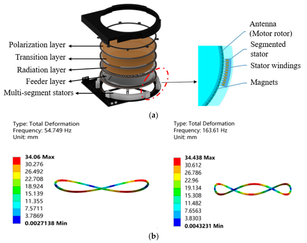
Figure 1. Schematic diagram of the functional layer of the HADDM: (a) Multi-layer structure of a VICTS antenna. (b) Deformation mode of the motor rotor in each antenna layer.
Actuators 15 00254 g001
Figure 2. Model of a multi-layer coaxial direct-drive servo mechanism: (a) top view; (b) front view.
Actuators 15 00254 g002
Figure 3. Simulation block diagram of the GHO-LADRC.
Actuators 15 00254 g003
Figure 4. Observation of composite disturbance.
Actuators 15 00254 g004
Figure 5. Comparison of disturbance observation errors.
Actuators 15 00254 g005
Figure 6. Partial enlarged view of the observed phase difference under high-frequency sinusoidal disturbance.
Actuators 15 00254 g006
Figure 7. Position tracking.
Actuators 15 00254 g007
Figure 8. Position tracking error.
Actuators 15 00254 g008
Figure 9. Velocity tracking.
Actuators 15 00254 g009
Figure 10. Velocity tracking error.
Actuators 15 00254 g010
Figure 11. Experimental setup of VICTS-HADDM.
Actuators 15 00254 g011
Figure 12. Dynamic response of HADDM at different speeds: (a) 2.5 rpm; (b) 5 rpm; (c) 10 rpm; (d) 20 rpm; (e) 30 rpm; (f) 40 rpm.
Actuators 15 00254 g012
Figure 13. Results of the open-loop speed response experiment: (a) Open-loop speed response without disturbance. (b) Open-loop speed response under disturbance.
Actuators 15 00254 g013
Figure 14. Disturbance rejection capability of closed-loop speed control: (a) Response of motor 2 at a target speed of 5 rpm under disturbance from motor 1 and 3. (b) Response of motor 2 at a target speed of 40 rpm under disturbance from motor 1 and 3.
Actuators 15 00254 g014
Figure 15. Communication performance testing under simulated carrier motion.
Actuators 15 00254 g015
Table 1. Controller parameters.
ParameterPIDLADRCGHO-LADRC
Stator phase resistance  R s     2.05   Ω   2.05   Ω   2.05   Ω
Stator phase inductance  R s  6.2 mH6.2 mH6.2 mH
Number of pole pairs      P n  125125125
Permanent magnet flux linkage    ψ f     0.01131   Wb   0.01131 Wb   0.01131 Wb
Electromagnetic damping coefficient  c 0     9.90   s 1   9.90   s 1   9.90   s 1
Moment of inertia      J     0.147768   kg m 2   0.147768   kg m 2   0.147768   kg m 2
Control gain  b 0  /   14.35   rad / ( A s 2 )   14.35   rad / ( A s 2 )
Observer bandwidth  ω o  /250 rad/s250 rad/s
Error feedback gain  l 1  /   3 ω o = 750   4 ω o = 1000
Error feedback gain  l 2  /   3 ω 0 2 = 187,500   6 ω 0 2 = 375,000
Error feedback gain  l 3  /   ω 0 3 = 15,625,000   4 ω 0 3 = 62,500,000
Error feedback gain  l 4  //   ω 0 4 = 3,906,250,000
Controller bandwidth  ω c  /40 rad/s40 rad/s
Proportional coefficient  k p  250   ω c 2 = 1600   ω c 2 = 1600
Integral coefficient  k i  1500//
Derivative coefficient  k d  12   2 ω c = 80   2 ω c = 80
Table 2. Comparison of experimental results with different control strategies.
PIDLADRCGHO—LADRC
Speed step response time0.6 s0.4–0.6 s according to different speeds≤0.4 s
Speed step overshoot5%00
Speed steady-state error000
Speed fluctuation under adjacent-layer disturbance±2 rpm±1.5–2 rpm according to different speeds≤±1 rpm
Table 3. Satellite signal strength attenuation under different motion states of the carrier.
Carrier Motion StatusGHO-LADRCPID
Roll: amplitude 10°, period 8 s<0.5 dB<1.0 dB
Azimuth: amplitude 15°, period 8 s<0.5 dB<0.5 dB
Azimuth: amplitude 15°, period 4 s<0.5 dB<0.5 dB
Pitch: amplitude 10°, period 8 s<1.0 dB<2.5 dB
Pitch: amplitude 5°, period 2.5 s<1.0 dB<2.5 dB
Pitch: amplitude 15°, period 25 s<1.0 dB<2.5 dB
Disclaimer/Publisher’s Note: The statements, opinions and data contained in all publications are solely those of the individual author(s) and contributor(s) and not of MDPI and/or the editor(s). MDPI and/or the editor(s) disclaim responsibility for any injury to people or property resulting from any ideas, methods, instructions or products referred to in the content.