Article

Active Piezoelectric Control of Three-Dimensional Vibration in a Flexible Circular Shaft via a Fuzzy Adaptive PID Algorithm

Key Laboratory of Structural Dynamics of Liaoning Province, College of Sciences, Northeastern University, Shenyang 110819, China
*
Author to whom correspondence should be addressed.
These authors contributed equally to this work.
Actuators 2026, 15(4), 226; https://doi.org/10.3390/act15040226
Submission received: 9 March 2026 / Revised: 7 April 2026 / Accepted: 14 April 2026 / Published: 17 April 2026
(This article belongs to the Special Issue Vibration Control Based on Intelligent Actuators and Sensors)

Abstract

Flexible circular shafts are critical components for power transmission in engineering systems. However, they are susceptible to complex three-dimensional coupled vibrations under multidirectional excitations, which can compromise operational stability and lead to structural fatigue. To address this issue, this paper presents an active control method for the three-dimensional vibration of a piezoelectrically driven flexible circular shaft via a fuzzy adaptive PID algorithm. The study begins by establishing a dynamic model of the system based on the Euler–Bernoulli beam theory and Lagrange equation. This model forms the foundation for the design of a fuzzy adaptive PID controller. The accuracy of the developed model is then validated through simulations and experiments. Subsequently, active vibration control (AVC) experiments are carried out to evaluate the vibration attenuation effectiveness of various control strategies (including a conventional PID controller as the benchmark for comparison) under different types of excitations applied at the shaft root. The results demonstrate that the proposed active control method has superior control performance, and exhibits excellent vibration suppression performance, especially under bidirectional excitation at the natural frequency, where the vibration suppression ratios in the two orthogonal directions reach 93.03% and 92.09%, respectively.

1. Introduction

Flexible circular shafts are structural components capable of undergoing significant elastic deformation. Owing to their lightweight characteristics, deformability, and high adaptability, they have been widely employed in various engineering fields, such as remote actuators for robot joints [1], medical devices [2,3], and support shaft system in unmanned underwater vehicle [4]. However, excessive vibration caused by external disturbances and internal dynamic coupling can lead to system instability [5], thereby degrading the service life and operational accuracy of the equipment [6]. Therefore, developing effective control strategies to suppress vibration in such structures is of great importance, as it not only prolongs system lifespan and enhances structural performance but also reduces potential accidents caused by excessive vibration.
Piezoelectric actuators are devices that utilize the inverse piezoelectric effect of piezoelectric materials to achieve mechanical braking or driving. They offer advantages such as rapid response speed, high precision and controllability, compact and lightweight structure, high output force and energy efficiency, and long service life and low maintenance requirements. As a result, numerous studies employ piezoelectric elements to suppress two-dimensional vibration in beams. Zhang et al. [7] proposed a novel two-dimensional electromechanical coupling model based on the transfer matrix method for accurately analyzing the out-of-plane bending vibration characteristics of cross-type piezoelectric beams. Wu and Deng [8] proposed a robust nonlinear control method based on operator theory, integrated with an “online Discrete Wavelet Transform (DWT)” for real-time signal processing and load estimation. This approach was designed to address the nonlinear vibration control problem of an L-shaped flexible robotic arm with unknown loads. Sun et al. [9,10,11] validated the effectiveness of the Linear Active Disturbance Rejection Control (LADRC) algorithm in suppressing vibrations in piezoelectric-driven beams under fixed harmonic excitation, variable harmonic excitation, and fixed harmonic excitation with measurement noise through numerical simulations and experiments. Thus, it is evident that piezoelectric actuators exhibit significant benefits in suppressing two-dimensional vibrations in beams. However, current research on the application of piezoelectric actuators to suppress three-dimensional vibration in flexible beams, rods, or shafts remains limited. Zehetner and Krommer [12] utilized piezoelectric layers to study the dynamic and control characteristics of a slender rod subjected to torsional vibration. It was demonstrated that piezoelectric control can significantly reduce the amplitudes of the first and second torsional modes.
To date, some schemes have been designed internationally for three-dimensional vibration reduction in flexible circular shafts. Song et al. [13] adjusted the stiffness and vibration characteristics of a thin-walled circular cross-section beam model by changing the fiber layup angles of composite materials (e.g., CUS layout) and utilized piezoelectric materials to act simultaneously as sensors and actuators to regulate the dynamic response of the model through proportional feedback control. Shen et al. [14] proposed the use of Active Constrained Layer (ACL) damping technology to control torsional vibration in circular cross-section rotating shafts, where the ACL structure consists of a piezoelectric constraining layer and a viscoelastic shear layer. Jiang et al. [15] achieved vibration suppression in a single-degree-of-freedom structure by utilizing damping generated from friction between an active flange ball bearing and a fixed shaft. This bearing–shaft assembly was integrated with a tuned mass damper to form a Friction Tuned Mass Damper (FTMD). Yan et al. [16] designed an Integrated Damping Bearing (IDB) that combines a ball bearing with an integrated damper, utilizing oil film damping and elastic support to reduce shaft vibration. Dong et al. [17] experimentally validated the effectiveness of nitrile rubber as a support material in improving the dynamic stability of shaft systems and noted that radial nitrile rubber supports provide better vibration reduction effects.
Most of these designs isolate vibration transmission from the shaft to other components by modifying the bearing structure, which adds complexity. Moreover, they do not fundamentally reduce shaft vibration and instead introduce additional stiffness to the overall system. The direct application of active control forces to the shaft body for suppressing three-dimensional vibration induced by multidirectional excitation remains an open challenge in the existing literature. Therefore, developing a structurally simple and highly efficient active vibration suppression device for flexible cylindrical shafts holds significant engineering value.
To fill this research gap, this paper proposes an active control method based on piezoelectric actuators, aiming to achieve effective suppression of three-dimensional vibration in flexible circular shafts under various excitation conditions. The main innovations of this study are as follows: (i) The piezoelectric actuator system is applied for the first time to the active three-dimensional vibration control of flexible circular shafts. Through control forces directly acting on the shaft body, multi-directional coupled vibrations are synergistically suppressed, providing a new approach for the multidimensional vibration control of continuum structures. (ii) For the first time, the performance of the fuzzy adaptive PID control algorithm is successfully verified for managing three-dimensional vibrational responses of a flexible shaft. This algorithm significantly reduces vibration amplitude while maintaining control accuracy, providing reliable algorithmic support for vibration control under complex operating conditions.
The structure of this paper is as follows: Section 2 establishes a dynamic model of a flexible circular shaft and designs a fuzzy adaptive PID controller. Section 3 validates the model accuracy through simulations and modal experiments. Section 4 presents active vibration control (AVC) experiments under three typical excitation conditions, systematically evaluating the vibration suppression effects of three control strategies. Section 5 summarizes the research conclusions, discusses the limitations of this work, and outlines future research directions.

2. Theoretical Model Derivation

2.1. Model Description

Figure 1 illustrates the schematic model of three-dimensional vibration control for a flexible shaft. A Cartesian coordinate system Oxyz is established at the lower fixed end of the shaft. The displacement functions u s , t , v ( s , t ) and w ( s , t ) describe the motion of the shaft along the x-, y-, and z-axes, respectively. Here, s represents the z-coordinate of points, and t represents time.
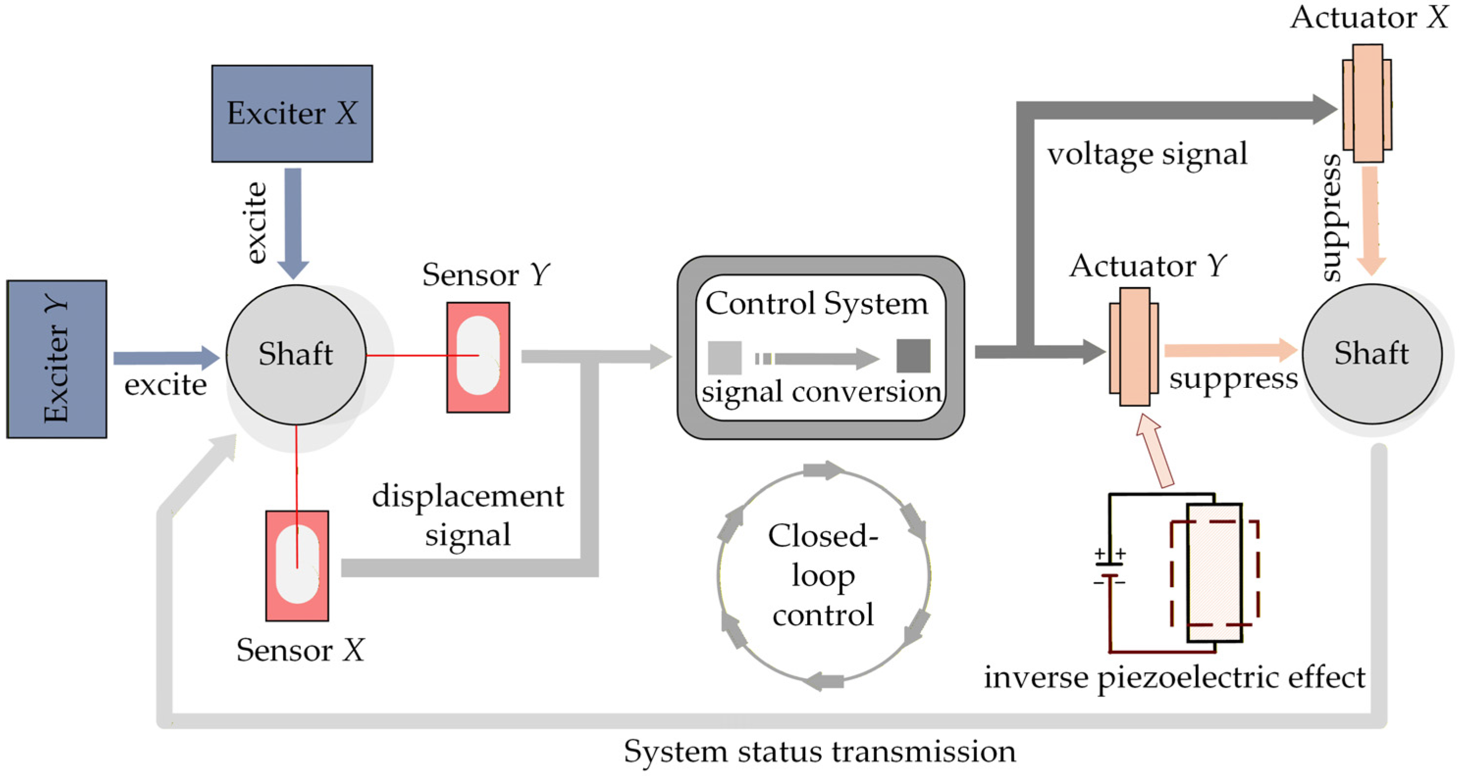
Figure 2 shows the workflow of three-dimensional vibration control. Firstly, exciters X and Y apply external excitation along the x and y directions, respectively, introducing three-dimensional vibration in multiple directions. Laser displacement sensor X and laser displacement sensor Y subsequently measure the corresponding displacements and transmit the measurements to the control system. Utilizing the acquired measurement signals, the system generates and issues real-time commands to drive the piezoelectric actuators. Ultimately, actuator X and actuator Y implement closed-loop control of the entire system through the inverse piezoelectric effect.
To facilitate subsequent theoretical modeling, the following notations and structural description are introduced. The flexible shaft is clamped at both ends by rigid supports. Its length and diameter are denoted by L s and d , respectively. Piezoelectric actuator X and piezoelectric actuator Y share identical dimensions (length L a , width b a , and thickness h a ) and are bonded to the adjacent surfaces of the shaft along the x and y directions. Their installation coordinate at the lowermost point is denoted as s a . Laser displacement sensors X and Y are mounted along the x and y directions to acquire vibration signals, with the measurement location denoted as s d . Exciter X and exciter Y, both operating in force control mode, are also arranged along the x and y directions and are connected to the shaft through a connector. Since the rods of the exciters impose additional constraints on the flexible shaft, these constraints are modeled as springs with stiffness coefficients k u and k v . The mass of the connector is represented by m , and its geometric center coincides with the excitation point of the exciter rod, located at s e .

2.1.1. The Total Kinetic Energy Equation of the System

The total kinetic energy of the structure consists of three components and is expressed as:
T = T s + T c + T a
where T s , T c , and T a denote the kinetic energies of the flexible shaft, connector, and piezoelectric actuators, respectively.
The kinetic energy of the flexible shaft is given by:
T s = 1 2 ρ s A s 0 L s u ( s , t ) t 2 + v ( s , t ) t 2 + w ( s , t ) t 2 d s
in which ρ s and A s denote the density and cross-sectional area of the shaft.
The kinetic energy of the connector is:
T c = 1 2 m u ( s e , t ) t 2 + v ( s e , t ) t 2 + w ( s e , t ) t 2
Since piezoelectric actuator X and piezoelectric actuator Y are identical, the kinetic energy of the piezoelectric actuators is expressed as:
T a = 1 2 ρ a A a s a s a + L a u t 2 + v t 2 d s
where ρ a denote the density and A a denote the cross-sectional area of the piezoelectric actuators.
Substituting Equations (2)–(4) into Equation (1) yields the total kinetic energy equation:
T = 1 2 ρ s A s 0 L s u ( s , t ) t 2 + v ( s , t ) t 2 + w ( s , t ) t 2 d s + 1 2 m u ( s e , t ) t 2 + v ( s e , t ) t 2 + w ( s e , t ) t 2 + 1 2 ρ a A a s a s a + L a u t 2 + v t 2 d s

2.1.2. The Total Potential Energy Equation of the System

The total potential energy of the structure consists of four components (the piezoelectric actuators are negligible due to their light weight) and can be expressed as follows:
U = U g + U s p + U s + U a
where U g , U s p , U s , and U a represent the gravitational potential energy of the connecter and the flexible shaft, the elastic potential energy of the spring, the bending strain energy of the flexible shaft, and the strain energy of the piezoelectric actuators, respectively.
The gravitational potential energy of the connector and the flexible shaft are written as:
U g = m g w ( s e , t ) + ρ s A s g 0 L s w ( s , t ) d s
The elastic potential energy of the spring can be expressed as follows:
U s p = 1 2 k u u ( s e , t ) 2 + k v v ( s e , t ) 2
The bending strain energy of the flexible shaft is written as follows:
U s = 1 2 E s I s 0 L s 2 u ( s , t ) s 2 2 + 2 v ( s , t ) s 2 2 + 2 w ( s , t ) s 2 2 d s
where E s represents Young’s modulus and I s = π d 4 / 64 represents the moment of inertia of the shaft.
The constitutive equation for piezoelectric materials is defined as [18]:
σ = c 11 E ε e 31 E D = e 31 ε + ϵ 33 S E
in which σ and ε denote the stress and strain along the z-axis, respectively; c 11 E represents the elastic modulus of the piezoelectric material; D denotes electric displacement;   E represents electric field strength, expressed as E = V ( t ) / h a , where V t denotes the applied voltage; e 31 = c 11 E d 31 represents the piezoelectric stress constant, in which d 31 is piezoelectric strain coefficient; and ϵ 33 S represents relative permittivity.
The electrical enthalpy density of piezoelectric materials can be defined as [19]:
H = 1 2 σ ε 1 2 D E
Substituting Equation (10) into Equation (11) yields:
H = 1 2 c 11 E ε 2 e 31 E ε 1 2 ϵ 33 S E 2
The strain energy of the actuators is expressed as follows:
U a = i = X , Y V i H d V i = i = X , Y V i 1 2 c 11 E ε 2 e 31 E ε 1 2 ϵ 33 S E z 2 d V i = 1 2 c 11 E I a s a s a + L a 2 u s 2 2 + 2 v s 2 2 d s 1 2 ϵ 33 S b a L a h a ( V 1 ( t ) 2 + V 2 ( t ) 2 )         + 1 2 c 11 E d 31 b a ( d + h a ) V 1 ( t ) s a s a + L a 2 u s 2 d s + V 2 ( t ) s a s a + L a 2 v s 2 d s
where I a represents the cross-sectional moment of inertia of the piezoelectric actuators, and V 1 t and V 2 t represent the driving voltages for piezoelectric actuators X and Y, respectively.
Substituting Equations (7)–(9) and (13) into Equation (6) yields the total potential energy equation of the system:
U = 1 2 E s I s 0 L s 2 u ( s , t ) s 2 2 + 2 v ( s , t ) s 2 2 + 2 w ( s , t ) s 2 2 d s + m g w ( s e , t ) + ρ s A s g 0 L s w ( s , t ) d s + 1 2 k u u ( s e , t ) 2 + k v v ( s e , t ) 2 + 1 2 c 11 E I a s a s a + L a 2 u s 2 2 + 2 v s 2 2 d s 1 2 ϵ 33 S b a L a h a ( V 1 ( t ) 2 + V 2 ( t ) 2 )   + 1 2 c 11 E d 31 b a ( d + h a ) V 1 ( t ) s a s a + L a 2 u s 2 d s + V 2 ( t ) s a s a + L a 2 v s 2 d s

2.1.3. System Dynamics Equation

The flexible shaft transverse displacements are defined by:
u ( s , t ) = i = 1 N Φ i ( s ) p i ( t ) = Φ T ( s ) p ( t ) v ( s , t ) = i = 1 N Ψ i ( s ) q i ( t ) = Ψ T ( s ) q ( t )
where N represents the count of truncated modes, p t and q t denote modal coordinates, and Φ T ( s ) and Ψ T ( s ) denote modal functions.
According to the non-scaling condition, it can be shown that [20]
u ( s , t ) s 2 + v ( s , t ) s 2 + w ( s , t ) s + 1 2 = 1
Expanding Equation (16) and neglecting higher-order terms yields:
w ( s , t ) s 1 2 u ( s , t ) s 2 + v ( s , t ) s 2
Integrating both sides of Equation (17) and substituting the axial boundary condition w 0 , t = 0 yields:
w ( s , t ) = 0 s 1 2 u ( ξ , t ) ξ 2 + v ( ξ , t ) ξ 2 d ξ
where ξ is used as the integration variable to distinguish the upper limit of integration from the integrand. This equation, derived strictly from the inextensibility condition of the Euler–Bernoulli slender beam, demonstrates that the longitudinal (z-direction) displacement of the shaft is fully and uniquely determined by the lateral bending displacements in the x and y directions, with no independent dynamic degree of freedom. In other words, by regulating the x- and y-directional displacements of the system, we can synchronously suppress the coupled axial displacement, thereby achieving effective control of the three-dimensional coupled vibrations of the flexible circular shaft. This deterministic mapping between transverse and axial vibrations is the core theoretical basis and key premise of the three-dimensional active vibration control strategy developed in this work.
The lateral boundary conditions for the structure are as follows:
u ( 0 , t ) = u ( L s , t ) = 0 , u ( 0 , t ) s = u ( L s , t ) s = 0 v ( 0 , t ) = v ( L s , t ) = 0 , v ( 0 , t ) s = v ( L s , t ) s = 0
Substituting this into Equation (15) yields:
Φ i ( 0 ) = Φ i ( L s ) = 0 , Φ i ( 0 ) s = Φ i ( L s ) s = 0 Ψ i ( 0 ) = Ψ i ( L s ) = 0 , Ψ i ( 0 ) s = Ψ i ( L s ) s = 0
The general solution for the free-vibration equation is as follows [21]:
Φ i ( s ) = Ψ i ( s ) = C 1 cos ( β s ) + C 2 sin ( β s ) + C 3 cosh ( β s ) + C 4 sinh ( β s )
Substituting the boundary conditions into Equation (20) yields:
Φ i ( s ) = Ψ i ( s ) = cosh ( β i s ) cos ( β i s ) cosh ( β i l s ) cos ( β i l s ) sinh ( β i l s ) sin ( β i l s ) [ sinh ( β i s ) sin ( β i s ) ]
where β i 4 = ρ S ω i 2 / E I , and ω i is the i-th natural frequency of the system. The value of β i l s is determined by the characteristic equation cos ( β i l s ) cosh ( β i l s ) = 1 .
By first inserting Equation (22) into Equation (15) and then substituting the resulting expression into both Equations (5) and (14), the final form is derived by substituting all of these into the Lagrange equation:
d d t T r ˙ T r + U r = W r
where r = [ p ( t ) , q ( t ) ] T .
Solving this yields the system dynamical equations:
M u p ¨ ( t ) + C u p ˙ ( t ) + K u p ( t ) + N u p ( t ) = F u + K X V 1 ( t ) M v q ¨ ( t ) + C v q ˙ ( t ) + K v q ( t ) + N v q ( t ) = F v + K Y V 2 ( t )
where M u and M v ; C u and C v ; K u and K v ; N u and N v ; F u and F v ; and K X and K Y represent the mass matrices, damping matrices, linear stiffness matrices, nonlinear stiffness matrices, force vectors along the x and y directions, and electromechanical coupling vectors, respectively. Detailed expressions of the matrices and vectors can be found in Appendix A.
Under structural damping conditions [22], Equation (24) can be simplified to:
M u p ¨ ( t ) + ( α 1 M u + α 2 K u ) p ˙ ( t ) + K u p ( t ) + N u p ( t ) = F u + K X V 1 ( t ) M v q ¨ ( t ) + ( α 1 M v + α 2 K v ) q ˙ ( t ) + K v q ( t ) + N v q ( t ) = F v + K Y V 2 ( t )
in which α 1 and α 2 denote Rayleigh proportionality constants.

2.2. Fuzzy Adaptive PID Controller Design

Multiplying the two sides of the two equations in Equation (25) by M u 1 and M v 1 respectively yields the following form:
p ¨ ( t ) = ( α 1 + α 2 M u 1 K u ) p ˙ ( t ) M u 1 K u p ( t ) M u 1 N u p ( t ) + M u 1 F u + M u 1 K X V 1 ( t ) q ¨ ( t ) = ( α 1 + α 2 M v 1 K v ) q ˙ ( t ) M v 1 K v q ( t ) M v 1 N v q ( t ) + M v 1 F v + M v 1 K Y V 2 ( t )
We unify nonlinearities and external disturbances as total disturbance, as shown in the following equation:
d u ( t ) = M u 1 N u p ( t ) + M u 1 F u d v ( t ) = M v 1 N v q ( t ) + M v 1 F v
The standard controlled second-order equation is obtained:
p ¨ ( t ) = ( α 1 + α 2 M u 1 K L v ) p ˙ ( t ) M u 1 K u p ( t ) + M u 1 K X V 1 ( t ) + d u ( t ) q ¨ ( t ) = ( α 1 + α 2 M v 1 K L v ) q ˙ ( t ) M v 1 K v q ( t ) + M v 1 K Y V 2 ( t ) + d v ( t )
We select the displacement at the shaft measurement point as the control input:
  • x-direction measured displacement:
u ( t ) = u ( s d , t ) = i = 1 N Φ i ( s d ) p i ( t ) = Φ T ( s d ) p ( t )
  • y-direction displacement at the measurement point:
v ( t ) = v ( s d , t ) = i = 1 N Ψ i ( s d ) q i ( t ) = Ψ T ( s d ) q ( t )
Since the excitation amplitude applied in our experiments is maintained at a low level, the nonlinear effects of the system do not play a dominant role, and the system response is dominated by low-order vibration modes. We therefore retain the first two vibration modes in the reduced-order model, that is, N = 2.
The active suppression target is to minimize the displacement measurement toward zero. The reference signal is taken as u r ( t ) = 0 , v r ( t ) = 0 . Thus, the error signal is:
e u ( t ) = u r ( t ) u ( t ) = Φ T ( s d ) p ( t ) , e v ( t ) = v r ( t ) v ( t ) = Ψ T ( s d ) q ( t )
We apply fuzzy adaptive PID control to the output voltage of piezoelectric actuator X:
V 1 ( t ) = K p u ( t ) e u ( t ) + K i u ( t ) 0 t e u ( τ ) d τ + K d u ( t ) e u ( t )
For the output voltage of piezoelectric actuator Y,
V 2 ( t ) = K p v ( t ) e v ( t ) + K i v ( t ) 0 t e v ( τ ) d τ + K d v ( t ) e v ( t )
To enhance the system’s adaptability to d u and d v , the fuzzy adaptive PID gains are updated online based on the error state:
K p ( t ) = K p + Δ K p ( t ) , K i ( t ) = K i + Δ K i ( t ) , K d ( t ) = K d + Δ K d ( t )
Selecting the error e(t) and the error rate ec(t) as control inputs, the output increments ΔKp(t), ΔKi(t), and ΔKd(t) follow the following damping rules: (i) When e(t) increases, increase Kp(t) to enhance rapid damping capability. (ii) When e(t) is small but residual error persists, increase Ki(t) to improve steady-state suppression. (iii) When ec(t) is large, increase Kd(t) to enhance equivalent damping and suppress overshoot.
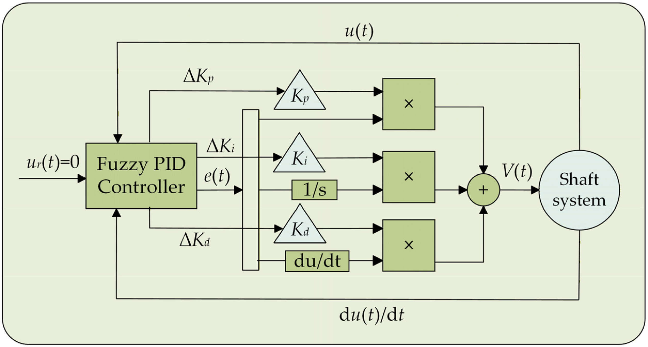
The core design details of the controller are as follows: The fuzzy subsets of all input and output variables are defined as {NB, NM, NS, ZO, PS, PM, PB}, with the standard universe of discourse for fuzzy inference uniformly set to [−3, 3] for all variables. Triangular membership functions are adopted for all variables, the Mamdani max-min method is used for fuzzy inference, and the center-of-gravity method is applied for defuzzification. The quantization factors for inputs e and ec are set to 5 and 5; the scaling factors mapping the normalized fuzzy output to actual physical increments are set to 20 for ΔKp(t), 10 for ΔKi(t), and 1400 for ΔKd(t), which correspond to a ±30% stable adjustment range relative to the initial PID parameters. The complete fuzzy control rules are listed in Table A1 in Appendix B, and the initial PID parameters are preliminarily tuned by the Ziegler–Nichols method based on system identification, then optimized via experimental debugging. Figure 3 illustrates the workflow of the fuzzy adaptive PID controller.
Substituting Equation (32) into Equation (28) yields the closed-loop modal control equation in the x direction:
p ¨ ( t ) = ( α 1 + α 2 M u 1 K u ) p ˙ ( t ) M u 1 K u p ( t ) + M u 1 K X K p u ( t ) e u ( t ) + K i u ( t ) 0 t e u ( τ ) d τ + K d u ( t ) e u ( t ) + d u ( t )
Similarly, the closed-loop modal control equation for the y direction is:
q ¨ ( t ) = ( α 1 + α 2 M v 1 K v ) q ˙ ( t ) M v 1 K v q ( t ) + M v 1 K Y K p v ( t ) e v ( t ) + K i v ( t ) 0 t e v ( τ ) d τ + K d v ( t ) e v ( t ) + d v ( t )

3. Experimental SETUP and Model Validation

In the experiment, the shaft material is polymethyl methacrylate (PMMA) with the following properties: Young’s modulus E s is 2.98 × 10⁹ Pa, density ρ s is 1190 kg/m3, and Poisson’s ratio v is 0.36. The geometric dimensions of the shaft are as follows: length L s is 776 mm, and diameter d is 8 mm. The piezoelectric actuators use PZT-5H material. The material properties (provided by Riyue Piezoelectric Technology Co., Ltd., Shaoxing, China) are as follows: elastic modulus E a is 75 × 109 Pa, density ρ a is 7000 kg/m3, Poisson’s ratio v is 0.35, and piezoelectric strain constant d 31 is −180 × 10−12 C/N. Their geometric dimensions are as follows: length L a is 120 mm, width b a is 5 mm, and thickness h a is 1 mm. The connector is a cube with a side length of 25 mm and a mass of 80 g. The equivalent spring stiffness in two orthogonal directions is set to 2 × 10⁵ N/m, which is calibrated by the experimentally measured natural frequencies of the shaft system.
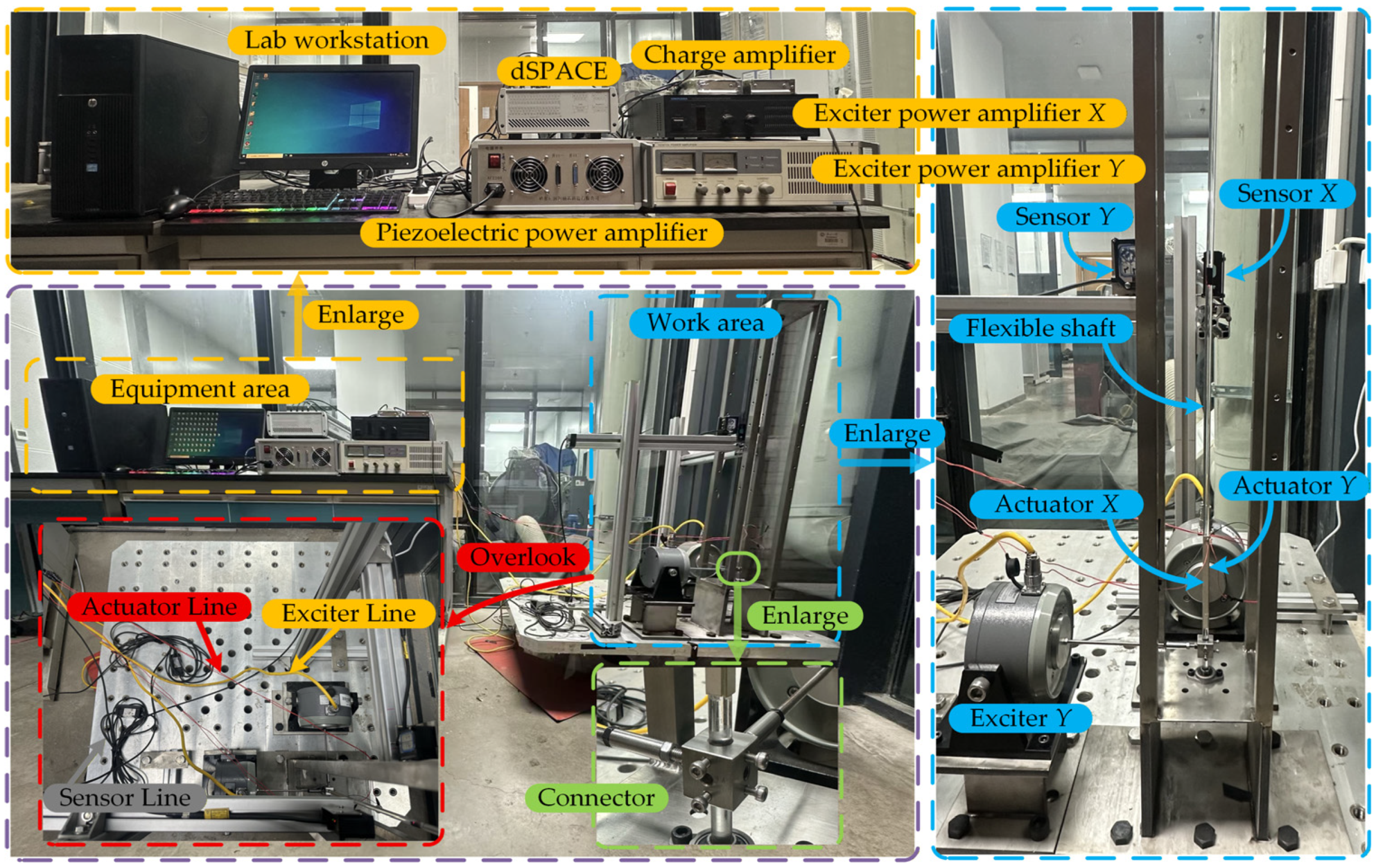
Figure 4 presents the overall structural layout of the three-dimensional vibration suppression experimental platform and its supporting equipment. Exciter X and exciter Y are horizontally arranged along the x and y directions on the experimental platform, respectively. They are connected to the flexible shaft fixed at both ends via a connector. The excitation centers and the connector positions are distributed at the same axial location, specifically 34 mm from the shaft’s lower fixed end. The piezoelectric actuators are mounted orthogonally along the corresponding shaft directions, with their bottom surfaces positioned 50 mm above the lower fixed end. For displacement measurement, laser sensors X and Y are mounted diametrically opposite along the x- and y-axes of the shaft, with their measurement points at a distance of 437 mm from the bottom end of the shaft.
To effectively suppress three-dimensional shaft vibration, the installation positions of piezoelectric actuators require optimized design to enhance vibration suppression efficacy. Research by Zheng et al. [23] indicates that positioning piezoelectric actuators in regions with maximum structural modal strain energy generates stronger modal control forces, thereby achieving superior vibration suppression. Given that the flexible shaft studied is modeled as an isotropic linear elastic body with uniform Young’s modulus and Poisson’s ratio in all directions, the O-x-z plane is selected as the representative analysis plane. Modal characteristics of the flexible shaft within this plane are simulated and analyzed via the finite element software ANSYS Workbench 2025 R1. The simulation adopts the same geometric dimensions and material parameters of the flexible shaft as the actual experimental setup, uses SOLID186 high-order 3D solid elements for meshing, applies fixed support constraint at the shaft roots consistent with the experimental boundary conditions, and completes modal calculation through the Modal module of the aforementioned software. Figure 5 presents the first-order modal shape of the flexible shaft in the O-x-z plane and its corresponding modal strain energy density distribution. Due to structural symmetry, its distribution characteristics in the O-y-z plane are identical. Analysis indicates that the maximum modal strain energy occurs near the root region of the flexible shaft, while the maximum modal displacement appears slightly above the midpoint of the shaft segment. These simulation results further validate the placement of the instrumentation in this study.
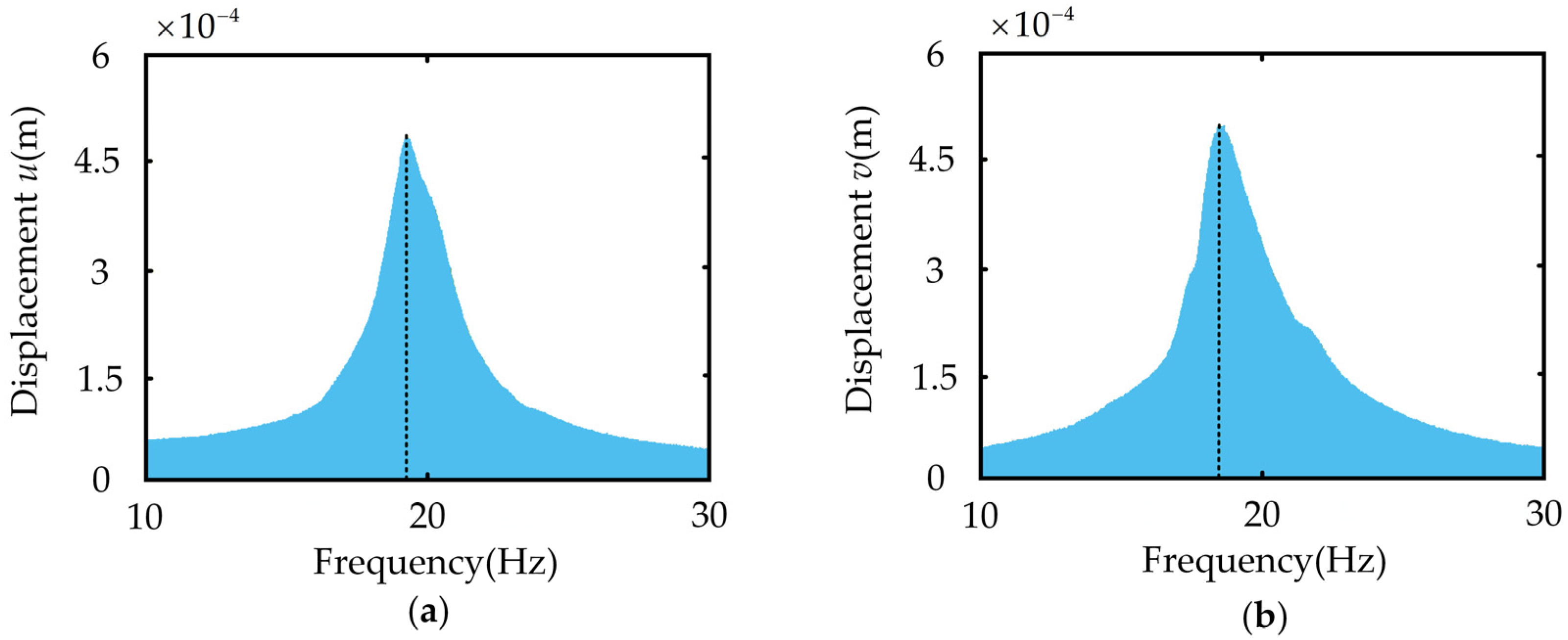
To validate the model’s effectiveness, external sweep frequency excitation ranging from 10 to 30 Hz is applied to the flexible shaft using the exciters. The actual first-order natural frequencies along the x and y directions are measured, with the results shown in Figure 6. Table 1 compares theoretical calculations with experimental measurements. The data in the table indicates that the theoretical values of the system’s first-order natural frequencies exhibit minimal deviation from the experimental values, demonstrating high consistency. This small error between the theoretical calculation and experimental measurement further verifies the rationality of the adopted modal truncation scheme and establishes a reliable foundation for subsequent experiments.
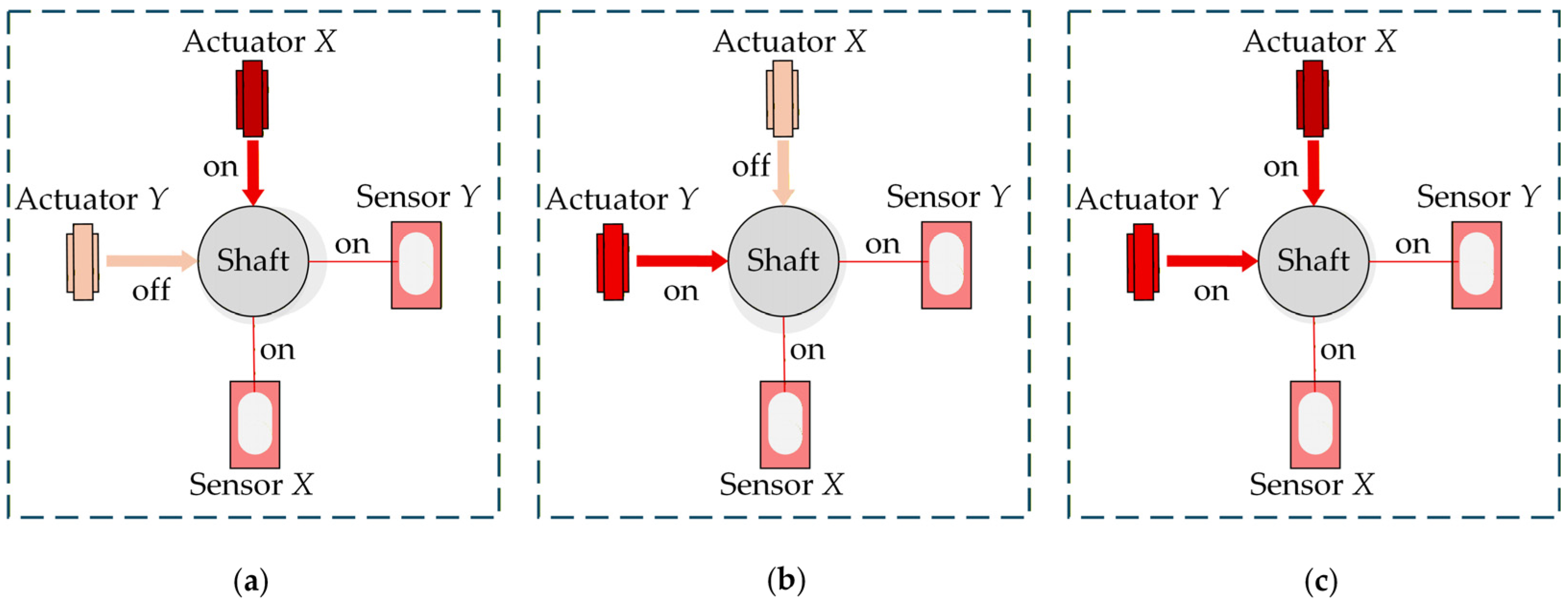
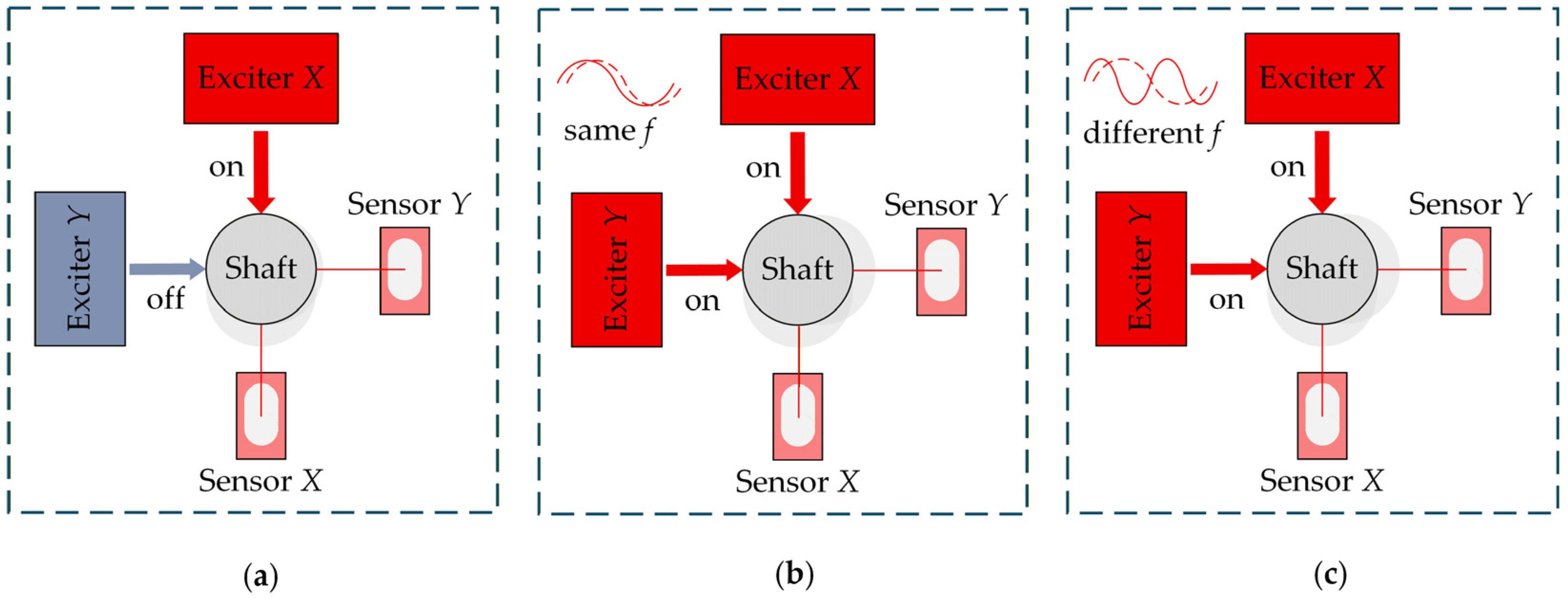
Subsequent active vibration control experiments in this study will be performed under three excitation types: unidirectional excitation, bidirectional excitation at the same frequency, and bidirectional excitation at the natural frequency. Unidirectional excitation refers to excitation applied only in the x direction or y direction. Since the vibrational behaviors of the flexible shaft are virtually identical in the x and y directions, this experiment focuses on excitation in the x direction as the representative case for study. Bidirectional excitation at the same frequency indicates simultaneous excitation at identical frequencies in both the x and y directions. Bidirectional excitation at the natural frequency refers to simultaneous excitation at different frequencies in the x and y directions. The specific implementation methods of various excitation types are shown in Figure 7. For the three distinct conditions described above, the suppression effectiveness of three control strategies is compared and analyzed: “Strategy-X” denotes that laser displacement sensor X provides feedback signals, with actuator X responsible for vibration suppression. At this time, laser displacement sensor Y is used solely for signal acquisition without participating in feedback, and actuator Y remains stationary. “Strategy-Y” denotes that laser displacement sensor Y provides feedback signals for actuator Y, which performs the vibration suppression. Laser sensor X is solely responsible for vibration signal acquisition without participating in feedback, and actuator X remains stationary. “Strategy-XY” describes an approach where both laser sensors provide coordinated feedback for monitoring, while actuators X and Y suppress vibrations in the x and y directions, respectively. Their corresponding implementations are shown schematically in Figure 8.

4. The AVC Experiment

To validate the effectiveness of the designed fuzzy adaptive PID algorithm in practical systems, this section evaluates the overall suppression performance of three control strategies under three distinct excitation types. Table 2 presents the control parameters for the three strategies under different excitation types.
To quantitatively evaluate the vibration control performance of all proposed control strategies, two core performance indicators are defined as follows.
The vibration suppression ratio η , applicable to all control strategies, is calculated as:
η = ( 1 A controlled A uncontrolled ) × 100 %
where Auncontrolled is the steady-state vibration amplitude of the target direction under the completely uncontrolled condition, Acontrolled is the steady-state amplitude of the same direction under the corresponding control strategy, and all test conditions remain consistent to ensure variable uniqueness.
The net vibration suppression ratio η n e t , exclusively applicable to Strategy-XY, is defined to quantify the pure additional vibration attenuation contribution of the target actuator, eliminating interference from cross-coupling suppression of the non-target actuator. Taking actuator X as an example, it is calculated as:
η net , X = ( 1 A X Y -control A Y -only -control ) × 100 %
where AY-only-control is the steady-state x-direction amplitude with only actuator Y activated, AXY-control is the amplitude of the same direction with both actuators X and Y synchronously activated, and the y-direction actuator’s net vibration suppression ratio follows the same logic.

4.1. Vibration Control Under Unidirectional Excitation

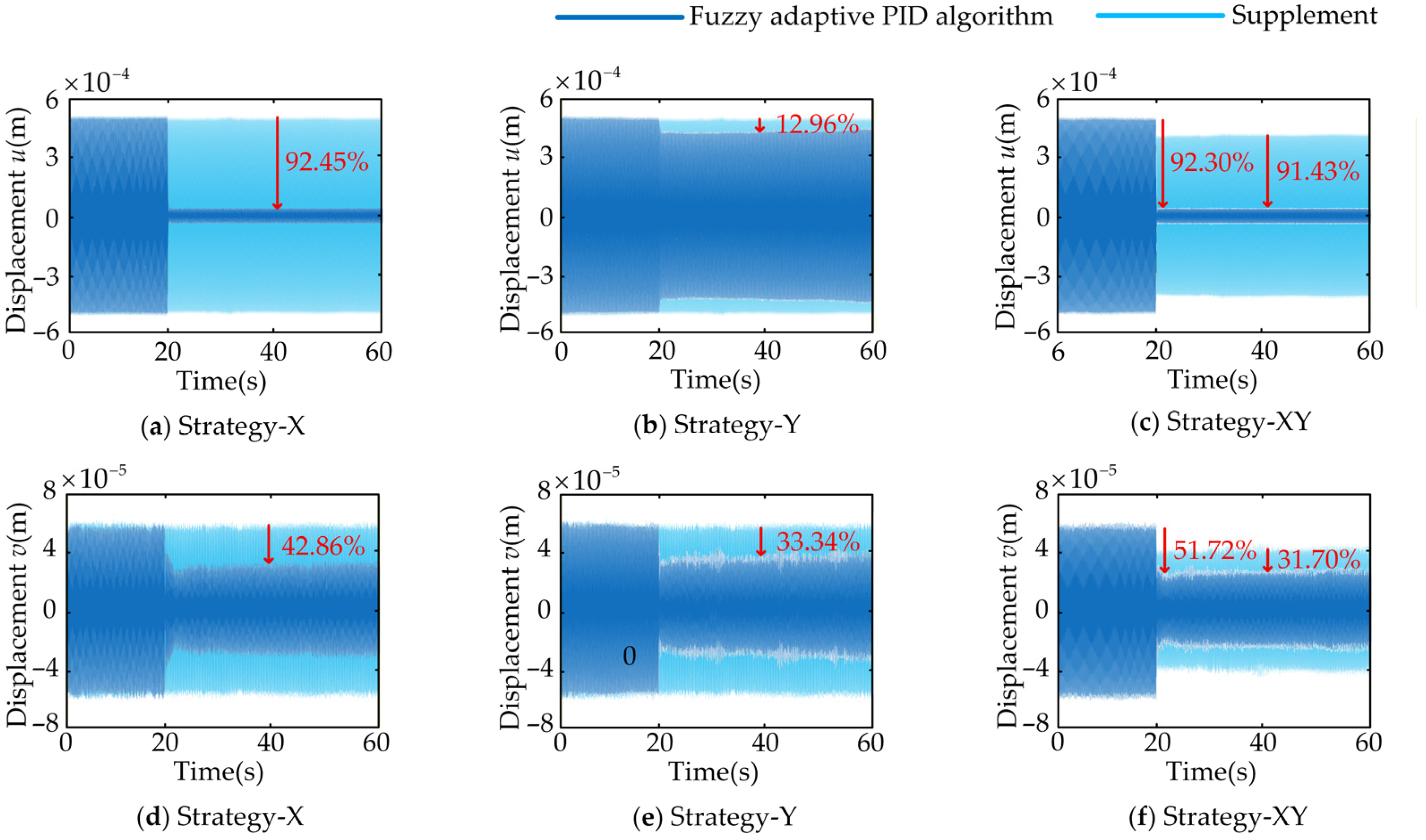
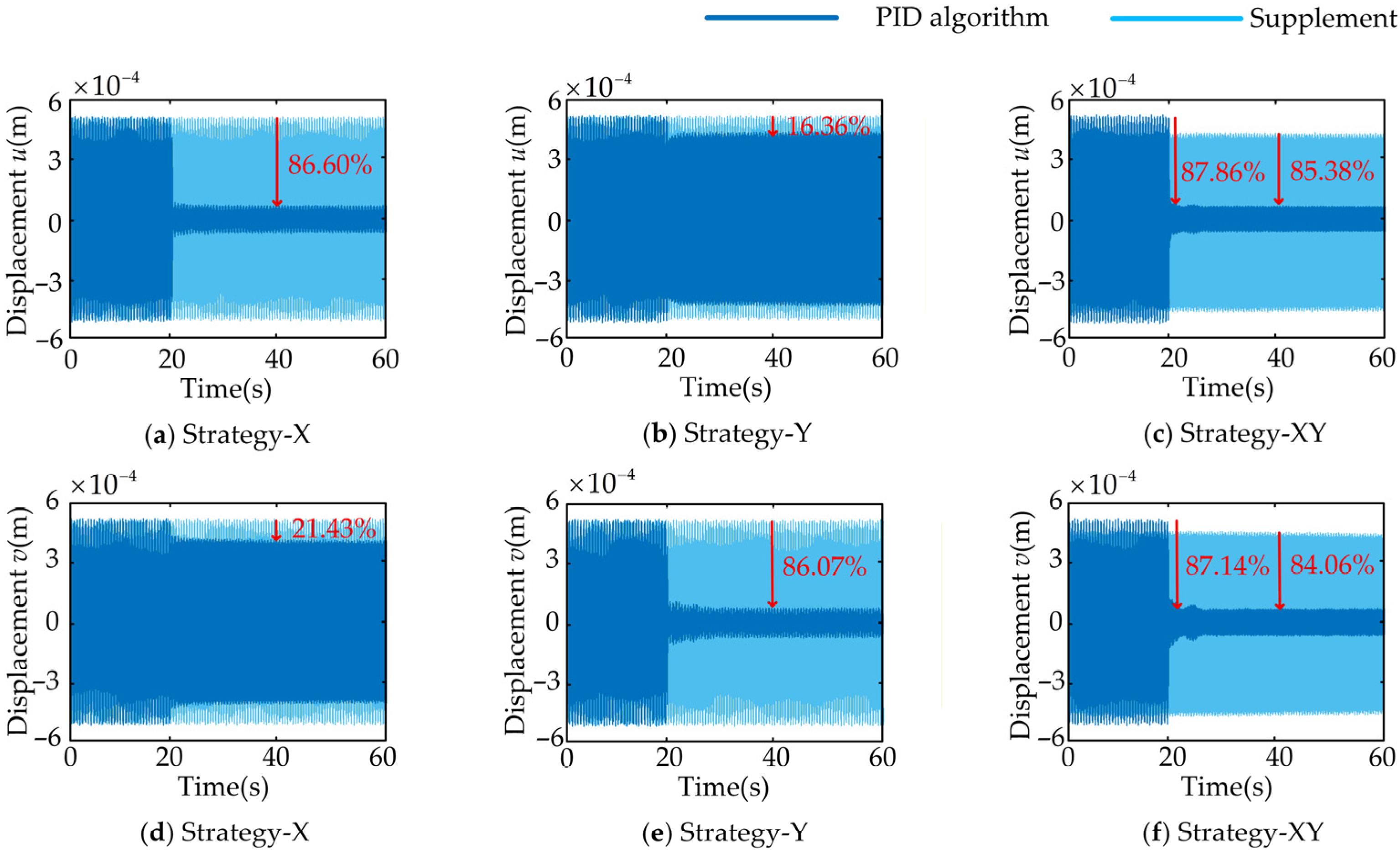
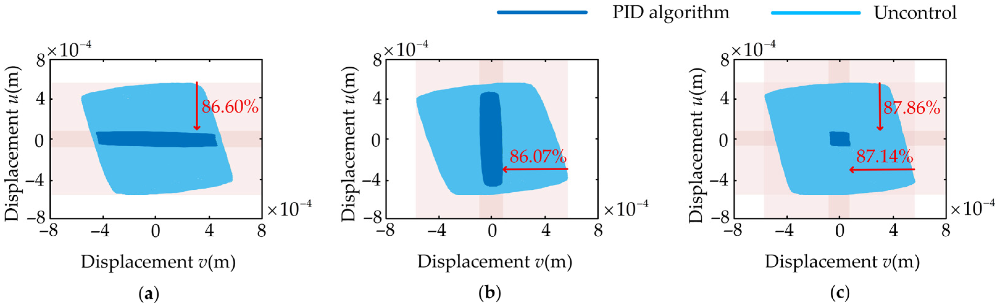
This section presents an investigation into the effectiveness of three distinct control strategies in suppressing vibrations of the flexible shaft induced by x-directional excitation. Figure 9 presents the displacement time-history curve of the flexible shaft with the control strategy activated. Figure 10 depicts the stationary path traced by the measured point on the flexible shaft. It should be emphasized that, for the light-blue curves in the result figures of this work, the legend label and physical meaning are clearly specified according to the core presentation purpose of each figure type: in all displacement time-history curves, the light-blue curve is labeled “Supplement”, which serves as the explicit calculation baseline for the corresponding performance indicators—representing the uncontrolled baseline vibration response (Auncontrolled) for vibration suppression ratio calculation under Strategy-X and Strategy-Y, and representing the vibration response under independent control of the non-target-direction actuator for net vibration suppression ratio calculation under Strategy-XY; in all stationary trajectories figures, the light-blue curve is labeled “Uncontrol”, which uniformly represents the uncontrolled steady-state motion trajectory of the structure with all piezoelectric actuators deactivated.
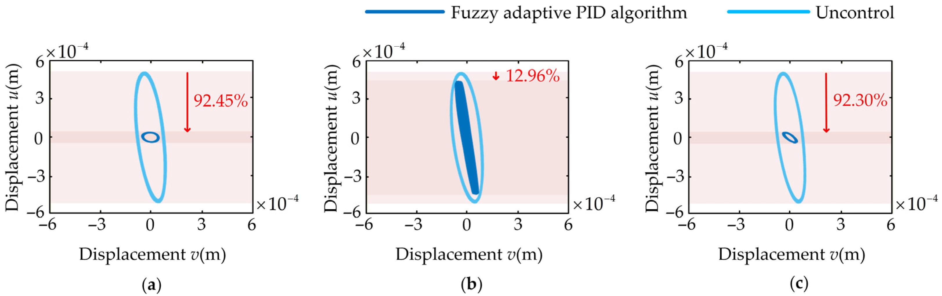
As shown in Figure 9, the input signal is a sinusoidal excitation along the x direction with the frequency of 19.2 Hz. This excitation frequency coincides with the natural frequency of the flexible shaft in the x direction. From the results, the x-direction excitation causes the expected primary response in the corresponding direction while also inducing a minor vibration in the y direction. The micro-vibrations exhibit an amplitude approximately one-tenth that of the primary vibrations. This phenomenon arises from coupling effects between vibrations along the x and y directions—vibrations in one direction excite vibrations in the other. After the shaft vibration has stabilized, the controller is activated at 20 s. The experimental data show that Strategy-X and Strategy-Y achieve vibration suppression ratios of 92.45% and 42.86%, and 12.96% and 33.34%, in the x and y directions, respectively. This indicates that Strategy-X and Strategy-Y both demonstrate superior control performance in their respective primary control directions, while exhibiting relatively weaker suppression capabilities in the opposite direction. It is noteworthy that Strategy-X achieves a suppression ratio as high as 92.45% for the primary vibration in the x direction. Interestingly, it also yields a 42.86% reduction in the coupled y-direction vibration. This value even surpasses the 33.34% suppression ratio attained by Strategy-Y in its corresponding y direction. This indicates that the direct control of the y-direction micro-vibration offers limited effectiveness, due to its inherently small amplitude. Strategy-X, however, effectively suppresses the amplitude of the primary vibration in the x direction, thereby reducing the vibrations transmitted to the y direction through coupling effects at the source. The Strategy-XY control strategy employs bidirectional piezoelectric actuators to achieve synergistic vibration suppression in orthogonal directions. To analyze its control mechanism in depth, the net vibration suppression ratio of each piezoelectric actuator in its corresponding direction was measured and recorded. Specifically, the contribution of the piezoelectric actuator X is measured along the x direction while piezoelectric actuator Y is active, and vice versa for the y direction, enabling a separate evaluation. The data show that the net suppression ratios contributed by actuators X and Y in their respective directions are 91.43% and 31.70%. This indicates that actuator Y has a minimal direct effect on the primary vibration in the x direction. Conversely, actuator X demonstrated a stronger capability to suppress the additional vibration along the y direction. This result aligns with the vibration coupling characteristics described previously. Regarding overall control performance, Strategy-XY achieves comprehensive vibration suppression ratios of 92.30% in the x direction and 51.72% in the y direction. Compared to the previous strategies, suppression performance in the x direction (maximum 92.45%) is largely maintained, while the suppression ratio for the micro-vibration in the y direction improves from 33.34% to 51.72%, further optimizing overall control effectiveness.
As shown in Figure 10, the stationary trajectories at the measurement point of the flexible shaft display a slightly inclined elliptical shape. This inclination is primarily attributed to a slight misalignment in the application of the external excitation, which deviates from the pure x direction due to assembly errors. After applying different control strategies, the stationary trajectories at the shaft measurement point show significant differences: appearing as a flattened ellipse, a coarse straight line, and an inclined ellipse, respectively. This phenomenon further confirms that Strategy-X and Strategy-Y can only effectively suppress vibrations in their target control direction, while performing poorly in the orthogonal direction. In contrast, Strategy-XY demonstrates excellent vibration suppression capabilities in both the x and y directions, significantly converging the composite motion trajectory of the flexible shaft and highlighting the superiority of its bidirectional cooperative control.
The experimental results reveal that in practical shaft systems, unidirectional excitation inevitably induces micro-vibrations in the orthogonal direction due to the coupling effect. Although a single actuator provides pronounced vibration suppression in the corresponding direction, its efficacy in the other direction remains markedly constrained. In contrast, a strategic configuration employing two orthogonally arranged actuators under cooperative control allows for the simultaneous attenuation of vibrations in both directions, achieving comprehensive vibration suppression. This approach significantly outperforms single-actuator control in overall vibration reduction performance.

4.2. Vibration Control Under Bidirectional Excitation at the Same Frequency

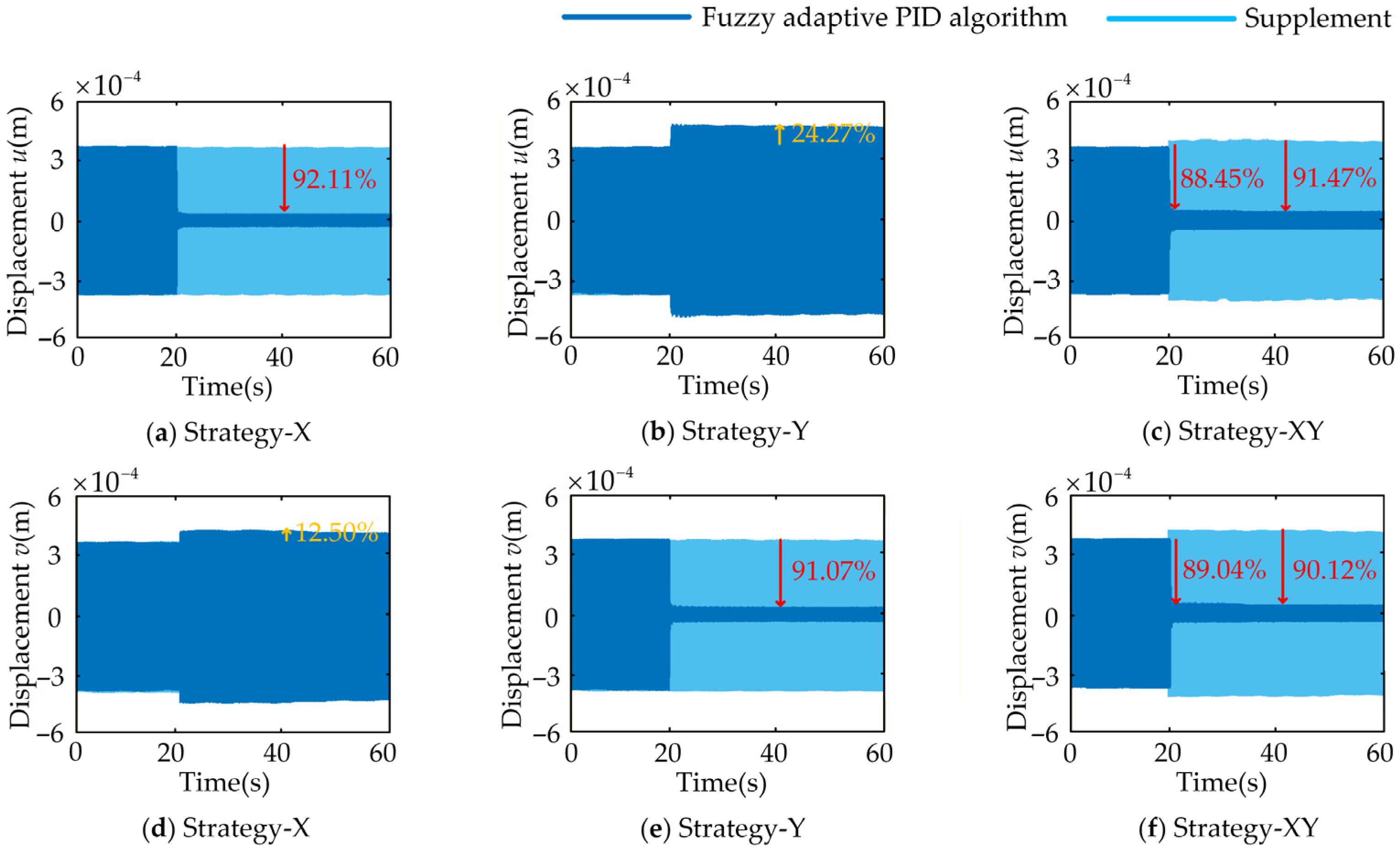
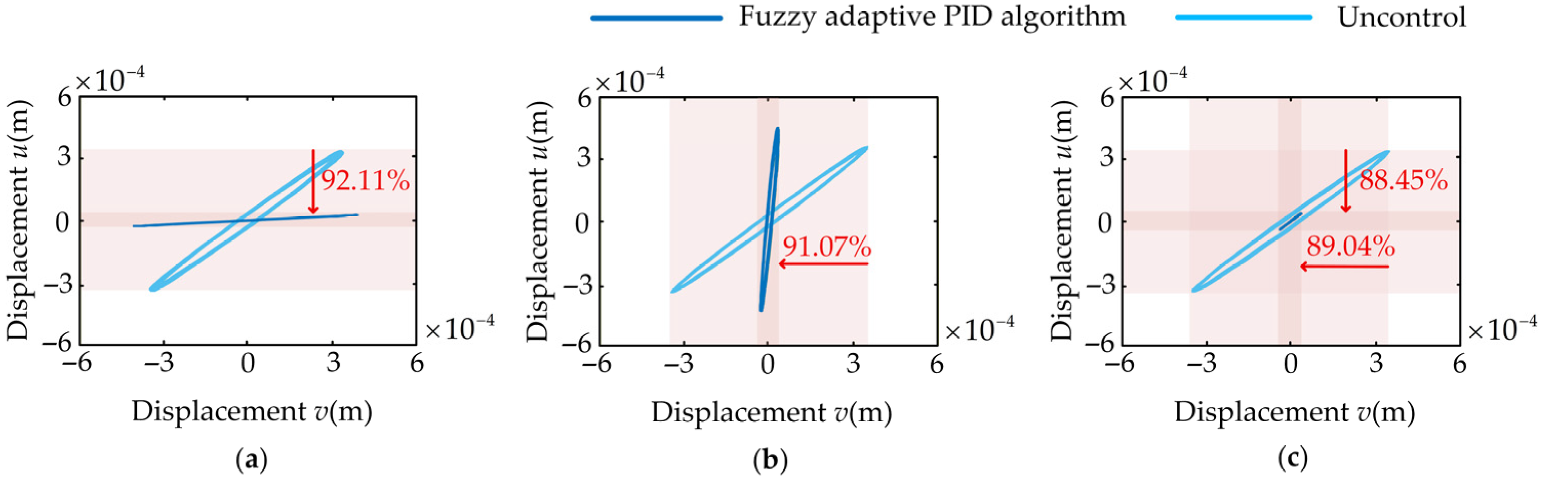
In practical engineering applications, structures often operate under complex multi-directional excitation environments, making the study of vibration control strategies under multi-directional excitation critically important. In this section, we analyze the vibration reduction performance of three strategies on a flexible shaft simultaneously subjected to excitation at the same frequency in both the x and y directions. Figure 11 and Figure 12 show the displacement time-history curves and stationary trajectories at the measurement points of the flexible shaft under this excitation type, respectively.
As shown in Figure 11, sinusoidal excitation at 18.8 Hz was simultaneously applied to the flexible shaft in the x and y directions. It can be observed that the bidirectional excitation at the same frequency caused vibrations with amplitudes of 0.35 mm and 0.36 mm at the measurement points in the x and y directions, respectively. After the shaft vibration stabilized, the controller was activated at the 20-s mark. The experimental data reveal that Strategy-X reduces the x-direction vibration amplitude by 92.11% but simultaneously increases the y-direction vibration amplitude by 12.50%. Strategy-Y reduces the y-direction vibration amplitude by 91.07% yet increases the x-direction vibration amplitude by 24.27%. This indicates that under bidirectional excitation at the same frequency, while Strategy-X and Strategy-Y effectively suppress vibrations in their target directions, they exacerbate vibrations in the orthogonal direction. Further analysis reveals that in Strategy-XY, the net vibration suppression ratios of piezoelectric actuators X and Y in their respective directions are 91.47% and 90.12%, comparable to the suppression effects of Strategy-X and Strategy-Y in their corresponding directions. This again confirms that single-direction actuators suppressing vibrations in the target direction adversely affect the orthogonal direction. Nevertheless, Strategy-XY achieves overall vibration suppression ratios of 88.45% and 89.04% in the x and y directions, respectively. Although the peak suppression ratios in the target directions are slightly lower than those of the single-direction strategies, the overall control performance shows a significant improvement. The reason for this, as concluded above, is that Strategy-XY enables both piezoelectric actuators X and Y to suppress vibrations in their respective directions. While these actuators reduce vibrations in their corresponding directions, they simultaneously exacerbate vibrations in the other direction.
As shown in Figure 12, the stationary trajectories of the measurement point under the three control strategies present an elongated oblique ellipse, an elongated oblique straight line, and a short straight line, respectively. This result further reveals that Strategy-X and Strategy-Y can suppress vibration in their target direction, but inevitably exacerbate vibration in the orthogonal direction. The underlying mechanism is that single-direction control ignores the inherent coupling between x- and y-directional vibrations under bidirectional co-frequency excitation: the control force applied only to the target direction breaks the system’s original vibration balance, causing vibration energy to transfer from the controlled direction to the uncontrolled orthogonal direction, which is directly reflected in the altered inclination angle of the steady-state trajectories. In contrast, Strategy-XY achieves simultaneous effective vibration suppression in both directions, making the steady-state trajectories of the measurement point converge significantly while maintaining the original inclination angle and approaching a stationary state.
The experimental results demonstrate that in actual multi-directional excitation environments, unidirectional vibration control strategies, while effectively suppressing vibrations in their target direction, exacerbate vibrations in orthogonal directions due to structural coupling. This confirms the limitations and potential adverse effects of single-direction control under multi-directional excitation. In contrast, the bidirectional cooperative control strategy coordinates piezoelectric actuators in both directions. It achieves net suppression effects approaching those of unidirectional strategies in each direction. Leveraging complementary bidirectional interactions, it systematically enhances overall vibration suppression. The strategy ultimately manifests in the motion trajectories: the slender oblique ellipse or oblique straight line observed under unidirectional control converges into a short straight line maintaining the original inclination angle, approaching a static state. This validates that bidirectional cooperative control exhibits superior comprehensive vibration suppression performance under multi-directional excitation conditions.

4.3. Vibration Control Under Bidirectional Excitation at the Natural Frequency

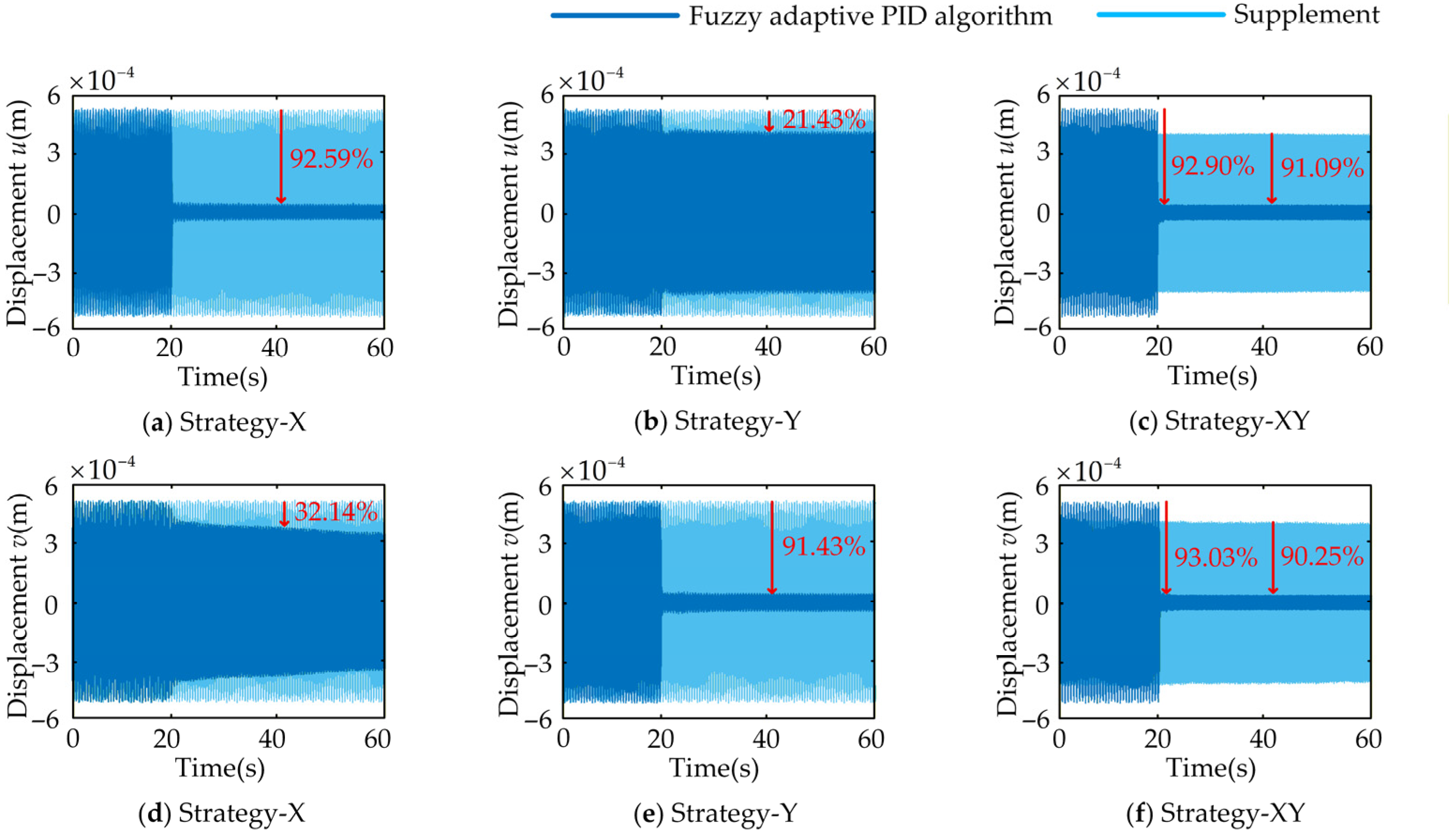
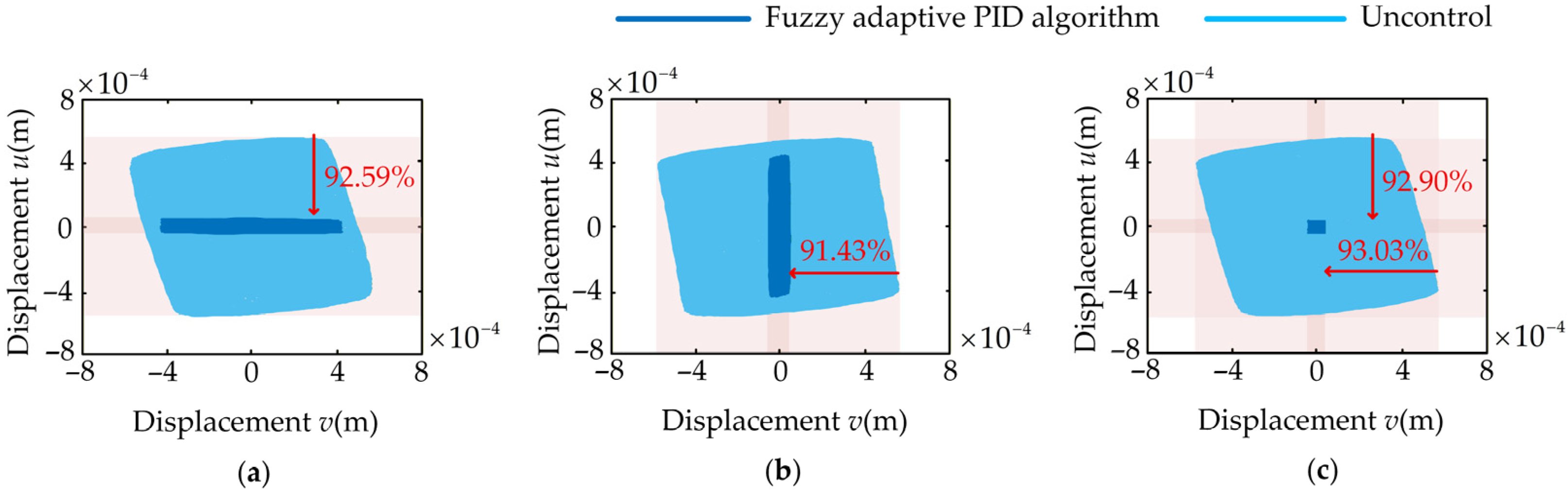
In engineering practice, resonance represents the most hazardous and destructive operating condition for structures. Therefore, investigating control strategies for three-dimensional vibration of flexible shafts under bidirectional excitation at the natural frequency holds significant engineering significance. This section evaluates the effectiveness of three control strategies in suppressing vibration when the system is excited at the respective natural frequencies of the x and y directions. Figure 13 and Figure 14 respectively present the displacement time-history curve and the stationary trajectories at the flexible shaft measurement points.
Sine excitations at the first-order natural frequency are applied to the flexible shaft in the x and y directions, respectively. Figure 13 shows that this excitation induced vibrations of 0.55 mm and 0.56 mm in the x and y directions, respectively, at the flexible shaft measurement points. The controller is activated at the 20-s mark, once the shaft vibration amplitude stabilizes. The data indicates that the vibration suppression ratios in the x and y directions for Strategy-X, Strategy-Y, and Strategy-XY are 92.59% and 32.14%, 21.43% and 91.43%, and 92.90% and 93.03%, respectively. In other words, under excitation at the natural frequency, Strategy-X and Strategy-Y effectively suppress vibrations in their respective directions but perform poorly in the opposite direction. However, Strategy-XY demonstrates superior performance by effectively suppressing vibrations in both directions, outperforming both Strategy-X and Strategy-Y. The net vibration suppression ratios of Strategy-XY in the x and y directions are 91.09% and 90.25%, respectively, slightly lower than the vibration suppression ratios of Strategy-X and Strategy-Y in their respective corresponding directions. This further demonstrates that Strategy-XY, by coordinating the dual piezoelectric actuators, significantly enhances the control effectiveness over the flexible shaft.
To more intuitively demonstrate the vibration reduction effects of each control strategy, Figure 14 shows the stationary trajectories of the shaft before and after control. Although sinusoidal excitations of different frequencies are applied to the flexible shaft in the x and y directions with a frequency ratio of 1.0378 (a rational number), theoretically resulting in closed trajectories, the extremely close frequencies produce a long closure period. Consequently, quasi-periodic trajectories are observed that do not close but eventually fill the entire quadrilateral region. As shown in Figure 14, under the three control strategies, the motion trajectories at the measurement points respectively form a horizontal rectangle, a vertical rectangle, and a near-square shape. This result indicates that under bidirectional excitation at the natural frequency, Strategy-XY achieves more comprehensive and balanced suppression of the flexible shaft’s three-dimensional vibration.
The experimental results demonstrate that under bidirectional excitation at the natural frequency, unidirectional control strategies Strategy-X and Strategy-Y achieve over 90% vibration suppression in their respective directions but exhibit limited effectiveness in the orthogonal direction. Unidirectional control shows clear limitations in resonant environments. In contrast, the bidirectional cooperative Strategy-XY achieves over 92% vibration suppression in both the x and y directions, delivering more balanced and comprehensive overall control performance. Regarding motion trajectories, unidirectional control produces compressed rectangular paths along the control direction, whereas Strategy-XY converges trajectories into near-square shapes. Bidirectional vibrations are synchronously suppressed, enabling system stability even under resonance conditions. This demonstrates the significant engineering value of bidirectional cooperative control, which greatly enhances the suppression of three-dimensional shaft vibrations under resonance, the most hazardous operating condition.

4.4. Comparison of PID and Fuzzy Adaptive PID Algorithms

To validate the control performance advantages of the fuzzy PID algorithm over the conventional PID algorithm, this section builds upon the research framework established in Section 4.3, focusing on a comparative analysis of the control effectiveness of both algorithms for the three-dimensional vibration of the flexible shaft. Figure 15 and Figure 16 respectively present the controlled response curves and steady-state motion trajectories at the measurement points when the flexible shaft is subjected to sinusoidal excitation at the natural frequencies under conventional PID algorithm control. The specific control parameter settings for the PID algorithm under this excitation method are detailed in Table 3.
As shown in Figure 15, under the PID algorithm control, sinusoidal excitation at the natural frequencies of both the x and y directions was applied to the flexible shaft. The experimental results indicate that the three control strategies employing the PID algorithm reduced the vibration amplitude of the flexible shaft in the x and y directions by 86.60% and 21.43%, 87.86% and 87.14%, and 16.36% and 86.07%, respectively. The steady-state motion trajectory of the flexible shaft measurement point shown in Figure 16 further demonstrates that the PID algorithm also achieves excellent vibration reduction effects.
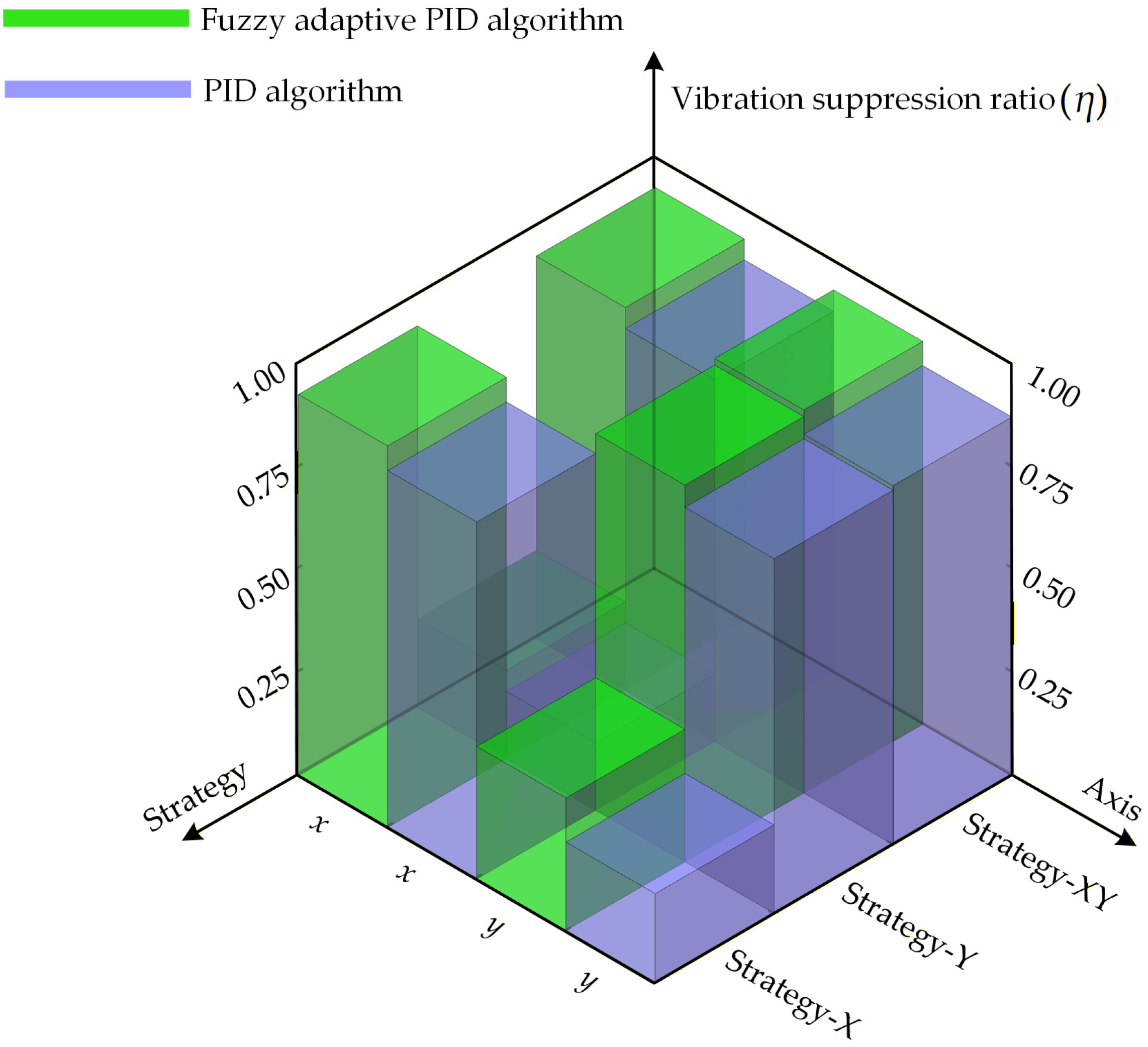
To compare the vibration suppression performance of the PID and fuzzy PID algorithms on the three-dimensional vibration of the flexible shaft in greater detail, Figure 17 presents the vibration suppression ratio of the piezoelectric actuator under both algorithms. It can be observed from Figure 17 that, across all three control strategies, the conventional PID algorithm exhibits inferior vibration suppression performance in both the x and y directions compared to the fuzzy PID algorithm. This result demonstrates that the fixed parameters of conventional PID struggle to adapt to system dynamics, whereas fuzzy PID demonstrates superior adaptability and control accuracy in time-varying and complex operating conditions through real-time parameter self-tuning.

5. Conclusions

This study innovatively applies piezoelectric actuators to the three-dimensional active vibration control of flexible shafts through theoretical analysis, simulation, and experimental validation. Focusing on three typical operating conditions, namely unidirectional excitation, bidirectional excitation at the same frequency, and bidirectional excitation at the natural frequency, the study systematically compares the vibration suppression performance of three control strategies: Strategy-X, Strategy-Y, and Strategy-XY. The key conclusions are summarized as follows:
(i) Under unidirectional excitation, the flexible shaft exhibits primary vibration in the excitation direction and secondary vibrations of smaller amplitude in the orthogonal direction due to structural coupling. While unidirectional control strategies effectively suppress vibrations in the target direction, their suppression capability in the orthogonal direction is limited. Single-direction control approaches struggle to eliminate the transmission of coupled vibrations.
(ii) Under bidirectional excitation, unidirectional control achieves high-efficiency vibration suppression in the corresponding direction but lacks sufficient control capability for the orthogonal directions, potentially exacerbating vibrations there. Bidirectional cooperative control, by leveraging the coordinated operation of two piezoelectric actuators, achieves high-level vibration suppression simultaneously in both the x and y directions. Particularly under resonance conditions, bidirectional cooperative control demonstrates superior overall vibration suppression performance and stability.
(iii) Compared with conventional PID control, the proposed fuzzy adaptive PID algorithm achieves better vibration suppression performance under all three control strategies. This result verifies its excellent online parameter adaptation capability, which can effectively improve the energy efficiency of the control system and the operational reliability of the actuators while maintaining high control accuracy.
In summary, the cooperative control strategy adopting bidirectional piezoelectric actuators mounted near the root of the flexible shaft and driven by a fuzzy PID algorithm achieves efficient and balanced three-dimensional vibration suppression under multi-directional and multi-frequency excitation. This method boasts a compact structure and superior control performance, thus exhibiting considerable potential for engineering applications in fields with stringent vibration control requirements, such as precision instruments and aerospace engineering.
Nevertheless, several limitations of the current work should be explicitly noted. First, the experimental validation is primarily concentrated on vibration control near the system’s first-order natural frequency, and the suppression performance for higher-order modal vibrations has not been fully explored. Second, the current experiments were conducted under fixed excitation conditions; the response characteristics of the sensors and actuators, as well as the stability of the control strategy, under varying excitation amplitudes, different phase differences between x- and y-direction excitations, and random external disturbances have not been tested.
Future research will focus on conducting control experiments under multi-modal, variable excitation, and random disturbance conditions to further explore the adaptability of the proposed control strategy in complex wide-band excitation environments. Special attention will be devoted to the suppression mechanism of high-order modal vibrations, the dynamic response of sensors and actuators under complex working conditions, and the global optimization of control parameters.

Author Contributions

Conceptualization, C.H. and W.C.; methodology, C.H.; software, C.H.; validation, C.H., Y.L. and J.Z.; formal analysis, C.H.; resources, W.C.; data curation, Y.L.; writing—original draft preparation, C.H. and Y.L.; writing—review and editing, X.S., J.Z. and W.C.; visualization, C.H.; supervision, W.C.; funding acquisition, W.C. All authors have read and agreed to the published version of the manuscript.

Funding

This research was supported by the Natural Science Foundation of Liaoning Province Project (Grant No. 2023-MSBA-056), and the Fundamental Research Funds for the Central Universities (Grant No. N2305011).

Institutional Review Board Statement

Not applicable.

Informed Consent Statement

Not applicable.

Data Availability Statement

The data presented in this study are available upon reasonable request from the corresponding author.

Conflicts of Interest

The authors declare no competing interests.

Appendix A

The matrices and vectors in Equation (24) are expressed as follows.
  • Mass matrix
M u = m Φ ( s e ) Φ ( s e ) T + ρ s A s 0 L s Φ ( s ) Φ ( s ) T d s + ρ a A a s a s a + L a Φ ( s ) Φ ( s ) T d s
M v = m Ψ ( s e ) Ψ ( s e ) T + ρ s A s 0 L s Ψ ( s ) Ψ ( s ) T d s + ρ a A a s a s a + L a Ψ ( s ) Ψ ( s ) T d s
  • Stiffness matrix
K u = E s I s 0 L s Φ ( s ) Φ ( s ) T d s + c 11 E I a s a s a + L a Φ ( s ) Φ ( s ) T d s + k u Φ ( s e ) Φ ( s e ) T ρ s A s g 0 L s 0 s Φ ( ξ ) Φ ( ξ ) T d ξ d s m g 0 s e Φ ( ξ ) Φ ( ξ ) T d ξ
K u = E s I s 0 L s Ψ ( s ) Ψ ( s ) T d s + c 11 E I a s a s a + L a Ψ ( s ) Ψ ( s ) T d s + k v Ψ ( s e ) Ψ ( s e ) T ρ s A s g 0 L s 0 s Ψ ( ξ ) Ψ ( ξ ) T d ξ d s m g 0 s e Ψ ( ξ ) Ψ ( ξ ) T d ξ
  • Nonlinear stiffness matrix
N u = ρ s A s 0 L s 0 s Φ ( ξ ) T p ˙ 2 + Φ ( ξ ) T p Φ ( ξ ) T p ¨ + Ψ ( ξ ) T q ˙ 2 + Ψ ( ξ ) T q Ψ ( ξ ) T q ¨ d ξ 0 s Ψ ( ξ ) Ψ ( ξ ) T d ξ d s + m 0 s e Φ ( s ) T p ˙ 2 + Φ ( s ) T p Φ ( s ) T p ¨ + Ψ ( s ) T q ˙ 2 + Ψ ( s ) T q Ψ ( s ) T q ¨ d s 0 s e Ψ ( s ) Ψ ( s ) T d s + E s I s 0 L s Φ ( s ) T p Φ ( s ) T p + Ψ ( s ) T q Ψ ( s ) T q Φ ( s ) Φ ( s ) T + Φ ( s ) Φ ( s ) T d s
N v = ρ s A s 0 L s 0 s Ψ ( ξ ) T q ˙ 2 + Ψ ( ξ ) T q Ψ ( ξ ) T q ¨ + Φ ( ξ ) T p ˙ 2 + Φ ( ξ ) T p Φ ( ξ ) T p ¨ d ξ 0 s Φ ( ξ ) Φ ( ξ ) T d ξ d s + m 0 s e Ψ ( s ) T q ˙ 2 + Ψ ( s ) T q Ψ ( s ) T q ¨ + Φ ( s ) T p ˙ 2 + Φ ( s ) T p Φ ( s ) T p ¨ d s 0 s e Φ ( s ) Φ ( s ) T d s + E s I s 0 L s Ψ ( s ) T q Ψ ( s ) T q + Φ ( s ) T p Φ ( s ) T p Ψ ( s ) Ψ ( s ) T + Ψ ( s ) Ψ ( s ) T d s
  • Electromechanical coupling vector
K X = 1 2 c 11 E d 31 b a d + h a s a s a + L a Φ ( s ) d s
K Y = 1 2 c 11 E d 31 b a d + h a s a s a + L a Ψ ( s ) d s
  • Force vector
F u = F u Φ ( s d )
F v = F v Ψ ( s d )

Appendix B

The complete fuzzy control rules are presented in Table A1 below.
Table A1. Fuzzy control rules for the adaptive adjustment of PID parameters.
ecNBNMNSZOPSPMPB
e
ΔKp
NBPBPBPMPMPSZOZO
NMPBPBPMPSPSZONS
NSPMPMPMPSZONSNS
ZOPMPMPSZONSNMNM
PSPSPSZONSNSNMNM
PMPSZONSNMNMNMNB
PBZOZONMNMNMNBNB
ΔKi
NBNBNBNMNMNSZOZO
NMNBNBNMNSNSZOZO
NSNBNMNSNSZOPSPS
ZONMNMNSZOPSPMPM
PSNMNSZOPSPSPMPB
PMZOZOPSPSPMPBPB
PBZOZOPSPMPMPBPB
ΔKd
NBPSNSNBNBNBNMPS
NMPSNSNBNMNMNSZO
NSZONSNMNMNSNSZO
ZOZONSNSNSNSNSZO
PSZOZOZOZOZOZOZO
PMPBNSPSPSPSPSPB
PBPBPMPMPMPSPSPB

References

  1. Usman, M.; Hubert, T.; Khorasani, A.; Furnémont, R.; Vanderborght, B.; Lefeber, D.; Van de Perre, G.; Verstraten, T. Design and Development of Highly Torque Dense Robot Joint Using Flexible Shaft Based Remote Actuation. In Proceedings of the 2024 IEEE International Conference on Advanced Intelligent Mechatronics (AIM), Boston, MA, USA, 15–19 July 2024; pp. 140–147. [Google Scholar]
  2. Liu, Q.; Kobayashi, Y.; Noguchi, T.; Inko, E.; Sekiguchi, Y.; Zhang, B.; Ye, J.; Toyoda, K.; Hashizume, M.; Fujie, M.G. In Development of a 6-dof manipulator driven by flexible shaft for minimally invasive surgical application. In Proceedings of the 2013 35th Annual International Conference of the IEEE Engineering in Medicine and Biology Society (EMBC), Osaka, Japan, 3–7 July 2013; pp. 6261–6264. [Google Scholar]
  3. Loeve, A.J.; Van De Ven, O.S.; Vogel, J.G.; Breedveld, P.; Dankelman, J. Vacuum packed particles as flexible endoscope guides with controllable rigidity. Granul. Matter 2010, 12, 543–554. [Google Scholar] [CrossRef]
  4. An, Y.; Liu, C.; Liu, J.; Pan, G. Multibody dynamic study and optimization for a flexible support shaft system in unmanned underwater vehicle. Proc. Inst. Mech. Eng. Part K J. Multi-Body Dyn. 2024, 238, 238–249. [Google Scholar] [CrossRef]
  5. Jiang, L.; Wang, L. Influence of double disk flexible rotor internal damping on dynamic stability. At. Energy Sci. Technol. 2022, 56, 163–170. [Google Scholar]
  6. Amy, R.A.; Aglietti, G.S.; Richardson, G. Reliability analysis of electronic equipment subjected to shock and vibration—A review. Shock. Vib. 2009, 16, 45–59. [Google Scholar] [CrossRef]
  7. Zhang, S.; Wang, L.; Zhao, Z.; Feng, H.; Zhao, C. Two-dimensional electromechanical-coupling modeling for out-of-plane bending vibration of cross-type beams. Int. J. Mech. Sci. 2024, 274, 109273. [Google Scholar] [CrossRef]
  8. Wu, Y.; Deng, M. Operator-based robust non-linear vibration control for an l-shaped arm with unknown load by using on-line wavelet transform. IET Control Theory Appl. 2018, 12, 770–777. [Google Scholar] [CrossRef]
  9. Sun, X.G.; Chi, W.C.; Wang, Y.Q. Linear active disturbance rejection control algorithm for active vibration control of piezo-actuated beams: Theoretical and experimental studies. Thin-Walled Struct. 2024, 199, 111782. [Google Scholar] [CrossRef]
  10. Sun, X.G.; Chi, W.C.; Wang, Y.Q. Theoretical and experimental research on multi-modal vibration control of flexible beams via the multiple-input multiple-output decoupling control strategy. Eur. J. Mech.-A/Solids 2024, 108, 105420. [Google Scholar] [CrossRef]
  11. Sun, X.G.; Chi, W.C.; Li, J.; Wang, Y.Q. Three-dimensional vibration suppression of flexible beams under multi-directional excitations via piezoelectric actuators: Theoretical and experimental investigations. Alex. Eng. J. 2025, 129, 1039–1060. [Google Scholar] [CrossRef]
  12. Zehetner, C.; Krommer, M. Control of torsional vibrations in piezolaminated rods. Struct. Control Health Monit. 2012, 19, 574–589. [Google Scholar] [CrossRef]
  13. Song, O.; Jeong, N.-H.; Librescu, L.I. Vibration and stability control of smart composite rotating shaft. In Smart Structures and Materials 2000: Mathematics and Control in Smart Structures; SPIE: Bellingham, WA, USA, 2000; pp. 437–448. [Google Scholar]
  14. Shen, I.; Guo, W.; Pao, Y. Torsional vibration control of a shaft through active constrained layer damping treatments. In Proceedings of the ASME 1994 International Mechanical Engineering Congress and Exposition, Dallas, TX, USA, 16–21 November 1997. [Google Scholar]
  15. Jiang, J.; Ho, S.C.M.; Markle, N.J.; Wang, N.; Song, G. Design and control performance of a frictional tuned mass damper with bearing–shaft assemblies. J. Vib. Control 2019, 25, 1812–1822. [Google Scholar] [CrossRef]
  16. Yan, W.; Wu, B.; Pan, J.; Ye, D.; Fuyang, C. Design and evaluation of integral damping bearing for vibration suppression in multi-disk rotor systems. Machines 2024, 12, 883. [Google Scholar] [CrossRef]
  17. Dong, J.; Wang, X.; Zhang, J.; Gu, J. Experimental investigation of dynamic behavior of rotor-bearing system with nitrile rubber support. Proc. Inst. Mech. Eng. Part J J. Eng. Tribol. 2018, 232, 1502–1513. [Google Scholar] [CrossRef]
  18. Odegard, G.M. Constitutive modeling of piezoelectric polymer composites. Acta Mater. 2004, 52, 5315–5330. [Google Scholar] [CrossRef]
  19. Xin, Y.; Li, Z.; Huang, D.; Lu, Y. An electromechanical coupling peridynamic model for piezoelectric solids with defects. Int. J. Mech. Sci. 2025, 304, 110679. [Google Scholar] [CrossRef]
  20. Hosseini, S.; Khadem, S. Free vibrations analysis of a rotating shaft with nonlinearities in curvature and inertia. Mech. Mach. Theory 2009, 44, 272–288. [Google Scholar] [CrossRef]
  21. Gómez-Silva, F.; Zaera, R.; Loya, J.A. Buckling and free vibration modes of a multi-cracked variable stiffness euler–bernoulli beam in a winkler foundation with piecewise constant stiffnesses. Eng. Struct. 2025, 340, 120717. [Google Scholar] [CrossRef]
  22. Chambreuil, C.; Giry, C.; Ragueneau, F.; Léger, P. Physic-based and locally updated nonlinear damping model for cracked reinforced concrete beams. Comput. Struct. 2025, 319, 107983. [Google Scholar] [CrossRef]
  23. Zheng, B.; Yang, J. In Optimal actuator placement for active vibration control of intelligent structure. In Proceedings of the ISTM/2005: 6th International Symposium on Test and Measurement, Dalian, China, 1–4 June 2005; pp. 2552–2555. [Google Scholar]
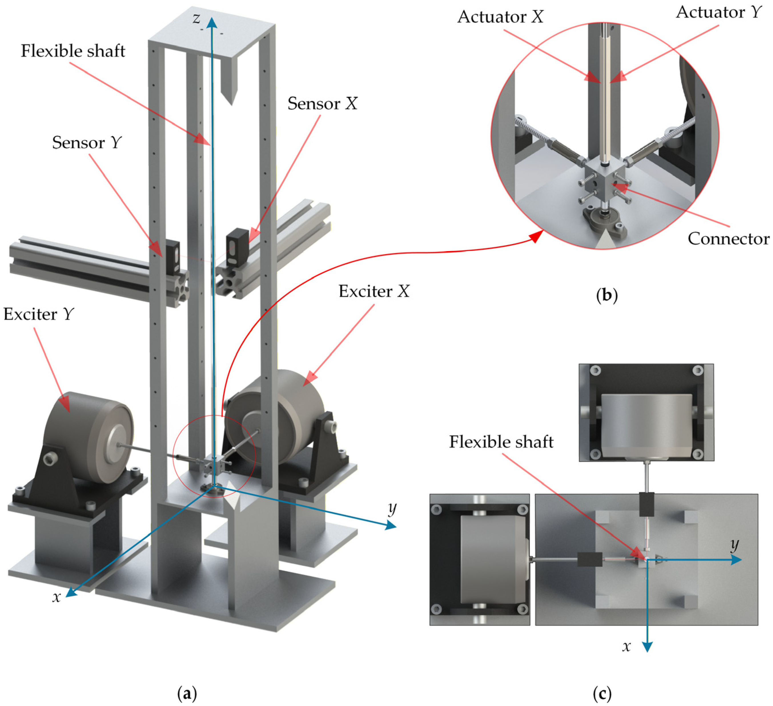
Figure 1. Modeling schematic for suppressing multidirectional vibrations in a flexible circular shaft: (a) three-dimensional view; (b) partial enlarged view; (c) top view.
Actuators 15 00226 g001
Figure 2. Schematic diagram of three-dimensional vibration control process.
Actuators 15 00226 g002
Figure 3. Schematic diagram of the fuzzy adaptive PID controller workflow.
Actuators 15 00226 g003
Figure 4. Experimental platform for active vibration control of the flexible shaft.
Actuators 15 00226 g004
Figure 5. Simulation results of modal characteristics for the flexible shaft: (a) first-order modal strain energy density distribution; (b) first-order mode shape.
Actuators 15 00226 g005
Figure 6. Schematic of amplitude–frequency response of the flexible shaft (a) in the x direction and (b) in the y direction.
Actuators 15 00226 g006
Figure 7. Schematic of various excitation types: (a) unidirectional excitation; (b) bidirectional excitation at the same frequency; (c) bidirectional excitation at the natural frequency.
Actuators 15 00226 g007
Figure 8. Schematic of different control strategies: (a) Strategy-X; (b) Strategy-Y; (c) Strategy-XY.
Actuators 15 00226 g008
Figure 9. Displacement time-history curve of the shaft under unidirectional excitation: (ac) in the x direction; (df) in the y direction.
Actuators 15 00226 g009
Figure 10. Stationary trajectories of the shaft under unidirectional excitation: (a) Strategy-X; (b) Strategy-Y; (c) Strategy-XY.
Actuators 15 00226 g010
Figure 11. Displacement time-history curve of the shaft under bidirectional excitation at the same frequency: (ac) in the x direction; (df) in the y direction.
Actuators 15 00226 g011
Figure 12. Stationary trajectories of the shaft under bidirectional excitation at the same frequency: (a) Strategy-X; (b) Strategy-Y; (c) Strategy-XY.
Actuators 15 00226 g012
Figure 13. Displacement time-history curve of the shaft under bidirectional excitation at the natural frequency: (ac) in the x direction; (df) in the y direction.
Actuators 15 00226 g013
Figure 14. Stationary trajectories of the shaft under bidirectional excitation at the natural frequency: (a) Strategy-X; (b) Strategy-Y; (c) Strategy-XY.
Actuators 15 00226 g014
Figure 15. Displacement time-history curve of the shaft under bidirectional excitation at the natural frequency under PID control: (ac) in the x direction; (df) in the y direction.
Actuators 15 00226 g015
Figure 16. Stationary trajectories of the shaft under bidirectional excitation at the natural frequency under PID control: (a) Strategy-X; (b) Strategy-Y; (c) Strategy-XY.
Actuators 15 00226 g016
Figure 17. Comparison of vibration suppression ratio between PID and fuzzy adaptive PID control.
Actuators 15 00226 g017
Table 1. First-order natural frequency of the flexible shaft in the x and y directions.
Theory (Hz)Experiment (Hz)Relative Error
x direction18.8019.202.13%
y direction18.8018.501.60%
Table 2. Control parameters for the three strategies under different excitation types.
StrategyExcitation TypeControl Parameters
KpuKiuKduKpvKivKdv
Strategy-Xunidirectional excitation20010014,000---
bidirectional excitation at the same frequency20010015,000---
bidirectional excitation at the natural frequency20010015,000---
Strategy-Yunidirectional excitation---20010014,000
bidirectional excitation at the same frequency---20010014,000
bidirectional excitation at the natural frequency---20010015,000
Strategy-XYunidirectional excitation20010016,00020010012,000
bidirectional excitation at the same frequency20010016,00020010016,000
bidirectional excitation at the natural frequency20010016,00020010016,000
Table 3. PID control parameters for the three strategies.
StrategyControl Parameters
KpuKiuKduKpvKivKdv
Strategy-X20010015,000---
Strategy-Y---20010015,000
Strategy-XY20010016,00020010016,000
Disclaimer/Publisher’s Note: The statements, opinions and data contained in all publications are solely those of the individual author(s) and contributor(s) and not of MDPI and/or the editor(s). MDPI and/or the editor(s) disclaim responsibility for any injury to people or property resulting from any ideas, methods, instructions or products referred to in the content.