1. Introduction
External gear pumps (EGPs) are based on a mechanically simple principle; however, the complex interactions among their internal components introduce significant challenges for design and optimization. Among these components, the lateral bushings exhibit dynamic behavior that is crucial for both the operational performance and the long- term durability of EGP. The lubrication gap between bushings and gears plays a key role in maintaining operational stability and pump efficiency. Achieving optimal performance therefore requires a detailed understanding of the lubrication phenomena, with particular emphasis on the mechanisms of pressure generation under transient and dynamic conditions. This includes investigating the combined effects of sliding and squeezing motions and bushing micromotion on the formation and stability of the lubricating film, which directly influence the load-carrying capacity.
Several studies have investigated the hydrodynamic behavior of lateral bushings, providing valuable insights into the complex interdependencies among surface kinematics, gap-height variations, and pressure development. Zardin et al. [
1] proposed a modeling approach to assess the hydromechanical efficiency of EGP by quantifying frictional losses in critical regions such as tooth tips, lateral clearances, and journal bearings, highlighting the significant impact of lateral and meshing losses on overall efficiency, particularly under low delivery pressures. Koç et al. [
2] performed an in-depth analysis of the lubrication mechanisms in bush type bearings of high-pressure gear pumps, focusing on the behavior of the bushings and the clearances between the gear end faces and the bushes. They showed that bush lubrication is strongly influenced by surface irregularities on the gears and by bush non-flatness, both of which affect hydrodynamic pressure generation and complicate the trade-off between sealing and lubrication. Cieślicki and Karpenko [
3] investigated the influence of pump deformation on which the circumferential clearance is presented; it presents a three-dimensional model of an external gear pump using the finite element method (FEM) under operating conditions—the simulation results indicate that the pump housing deforms under pressure, causing a significant increase in the circumferential gap height. Dhar and Vacca [
4] developed a fluid–structure interaction (FSI) model to simulate the lubricating gaps in external gear machines (EGMs), focusing on elasto-hydrodynamic effects. Their model, coupled with an axial balance formulation, predicts lubricant film thickness and lateral bushing position under various operating conditions, providing a powerful tool for optimizing the equilibrium of EGP components. Torrent et al. [
5] developed a comprehensive model to simulate and experimentally validate the movement of the floating bearing bushing in an EGP, relating it to pump parameterization and lubrication effects; their work, supported by laboratory and field tests, provided valuable insights into improving volumetric efficiency and bushing equilibrium. In a subsequent contribution, Torrent et al. [
6] introduced a bond graph-based modeling framework for floating bushings, offering a simple and fast tool to simulate the dynamic behavior of the bushing and analyze volumetric and mechanical efficiency variations over different operating conditions. Corvaglia et al. [
7] employed three-dimensional CFD simulations to evaluate tooth-space pressure and detect flow-rate reductions due to incomplete filling of the tooth spaces when inlet pressure is reduced, demonstrating that CFD models can accurately predict internal flow phenomena and quantify how manufacturing errors affect equilibrium conditions in the pump. Dhar and Vacca [
8] further advanced the study of lateral bushings by introducing a modeling approach that couples CFD with axial motion analysis to investigate axial balance and lubricating gaps in external gear machines, addressing the critical design challenge of simultaneously ensuring sealing, minimizing leakage-related power losses, and maintaining full-film lubrication to reduce wear. Thiagarajan et al. [
9] investigated the lubrication performance of EGP used in aerospace fuel delivery systems, focusing on frictional forces within the axial balance system; they showed that friction strongly affects the axial compensation behavior and, consequently, the equilibrium of the bushings, underlining the importance of improving the load bearing capacity and dynamic stability of lateral bushings in demanding applications.
Within this context, surface texturing has emerged as a powerful strategy to enhance hydrodynamic performance in lubricated interfaces. Early and recent work on textured sliders and thrust pads has shown that properly designed micro features can increase load-carrying capacity and reduce friction by locally modifying the pressure field and shear stress distribution [
10,
11,
12]. CFD-based thermohydrodynamic analyses of textured thrust bearings by Chalkiopoulos et al. [
13] and Fouflias et al. [
14] demonstrated that the optimal texture design depends sensitively on operating conditions, and that thermal and mechanical deformations can substantially alter the performance of nominally optimal geometries, reducing load capacity and increasing friction when deformations are not accounted for. Papadopoulos et al. [
15] extended this line of research by performing evolutionary optimization of trapezoidal micro texturing, showing that carefully tuned periodic dimple patterns can significantly increase load capacity for both parallel and mildly converging sliders.
Focusing on fluid power applications and on EGP, Casoli et al. [
16,
17,
18] examined the performance improvements obtained through surface texturing of bushings and lateral components by means of CFD simulations and bench tests. Their studies quantified how geometric characteristics of dimples, their distribution, and the onset of cavitation between micro features influence load-carrying capacity and hydromechanical efficiency, providing application-oriented guidelines for selecting texture parameters in gear pump bushings. These works establish surface texturing as a viable approach for tuning the hydrodynamic response of the lubrication film in EGP and provide a strong motivation to extend current analyses beyond static or quasi static performance metrics toward a full dynamic characterization.
From a dynamic perspective, hydrodynamically lubricated interfaces are often represented in terms of equivalent stiffness and damping coefficients, which govern the small amplitude response of rotor bearing systems and strongly influence stability. Classical rotodynamic formulations, such as those summarized by Childs [
19] and further developed by Jang and Lee [
20], show that fluid film bearings generate frequency-dependent stiffness and damping (including cross-coupled terms) that can either stabilize or destabilize the rotor depending on geometry and operating conditions. In parallel, Bao and Yang [
21] provided a comprehensive review of squeeze-film air damping in MEMS, clarifying the decomposition of the fluid film reaction into viscous (damping-like) and elastic (stiffness-like) components, and illustrating how film thickness, frequency, and gas compressibility jointly determine the dynamic response. For thrust bearings in turbomachinery, He and Byrne [
22] emphasized that accurate prediction of minimum film thickness, pad temperature and stiffness/damping characteristics is essential to avoid failure modes such as wear, overheating, excessive axial vibration, and loss of reliability.
Dynamic characteristics of journal and thrust bearings under hydrodynamic or hydrostatic lubrication have been extensively investigated. Storteig and White [
23] analyzed the dynamic behavior of fixed pad thrust bearings, quantifying stiffness, and damping from perturbed Reynolds equation solutions. Jang and Lee 20] determined coupled journal thrust dynamic coefficients via perturbation, revealing the importance of cross coupling in high-speed machinery. More recently, Tripkewitz et al. [
24] conducted an experimental and theoretical study on the dynamic stiffness of circular oil hydrostatic shallow recess thrust bearings, combining frequency response measurements with analytical modeling to show how recess depth, compressible volume and external capillaries affect dynamic stiffness and damping. Takenaka et al. [
25] applied CFD to evaluate static and dynamic characteristics of hydrodynamic journal bearings, demonstrating that dynamic coefficients can be extracted by simulating controlled oscillatory motions via mesh morphing and comparing results with experiments.
Several authors have directly targeted the identification of dynamic coefficients (stiffness, damping and, in some cases, added mass) using CFD-based strategies in seals and thrust bearings. Qin et al. [
26] proposed a three-dimensional CFD method, coupled with a structural model, to predict rotodynamic coefficients of oil thrust bearings by imposing harmonic perturbations and postprocessing the resulting unsteady reaction forces. Snyder and Braun [
27] compared perturbed Reynolds equation and full CFD models for sliding bearings, showing that CFD can capture effects beyond the scope of simplified formulations, especially in complex geometries. Building on this, Yamada et al. [
28] experimentally determined stiffness and damping coefficients of a squeeze film damper using a dilatant non-Newtonian fluid, highlighting the strong dependence of dynamic coefficients on excitation velocity and nonlinear rheological effects. Their work demonstrated the importance of accurately identifying frequency-dependent dynamic parameters for rotating machinery design.
While such studies provide valuable experimental insight at millimetric clearances and macro-scale damping devices, the extraction of dynamic coefficients in micrometric, textured thin-film interfaces typical of external gear pump bushings remains comparatively less explored, particularly using fully resolved CFD approaches under transient conditions.
The effect of surface texturing on dynamic coefficients has also begun to be quantified. Papadopoulos et al. [
29] characterized stiffness and damping in textured sector pad micro thrust bearings using CFD, considering both translational (squeeze) and tilting perturbations. They showed that appropriately designed texture patterns can simultaneously increase stiffness and reshape damping relative to smooth sliders, and that properly textured parallel pads can offer superior overall dynamic performance compared to conventional converging pads.
However, these studies primarily concern journal, hydrostatic, or thrust bearings with relatively simple geometries and boundary conditions and therefore do not directly address the highly asymmetric sector like lubrication gaps that form between the gear side face and the lateral bushings in external gear pumps. Moreover, although surface texturing has been shown to substantially affect both static and dynamic characteristics in thrust bearing configurations [
30,
31,
32,
33,
34], its influence on the dynamic response of the suction-side bushing gear lubrication film in EGP remains unexplored. There is a lack of quantitative information on how bushing micromotion, and micro dimples modify the effective stiffness and damping of the oil film under combined sliding and squeezing motions, low-pressure suction-side conditions, and the strongly transient gap evolution driven by tooth passage from the meshing zone to the inlet.
This paper addresses these gaps by focusing on the dynamic characteristics of the suction-side lubrication gap in EGP, through the calculation of effective stiffness and damping coefficients of the oil film between the gear side face and the lateral bushing. This research is focused on the suction side because in this application the minimum gap height is reached on this side because of the tilt of the bushing. Building on the CFD framework previously developed for textured lateral bushings in EGP [
35], the present study employs a three-dimensional sector model of the bushing gear interface to resolve local flow micromotion under realistic kinematics. A sequence of steady-state simulations at different gap heights is performed to construct the hydrodynamic force displacement relationship and to derive an effective stiffness. Transient simulations with a given approaching motion are then postprocessed, following concepts from CFD-based dynamic coefficient methodologies for sliding, journal, and thrust bearings [
30,
31,
32,
33,
34], to extract a physically consistent damping coefficient. In this way, this study provides a quantitative characterization of how bushing surface texturing modifies the stiffness and damping of the suction-side lubrication film in external gear pumps, offering design-oriented insights for improving axial stability, reducing wear, and enhancing overall pump performance.
2. Models
2.1. Bushing–Gear Interaction Model
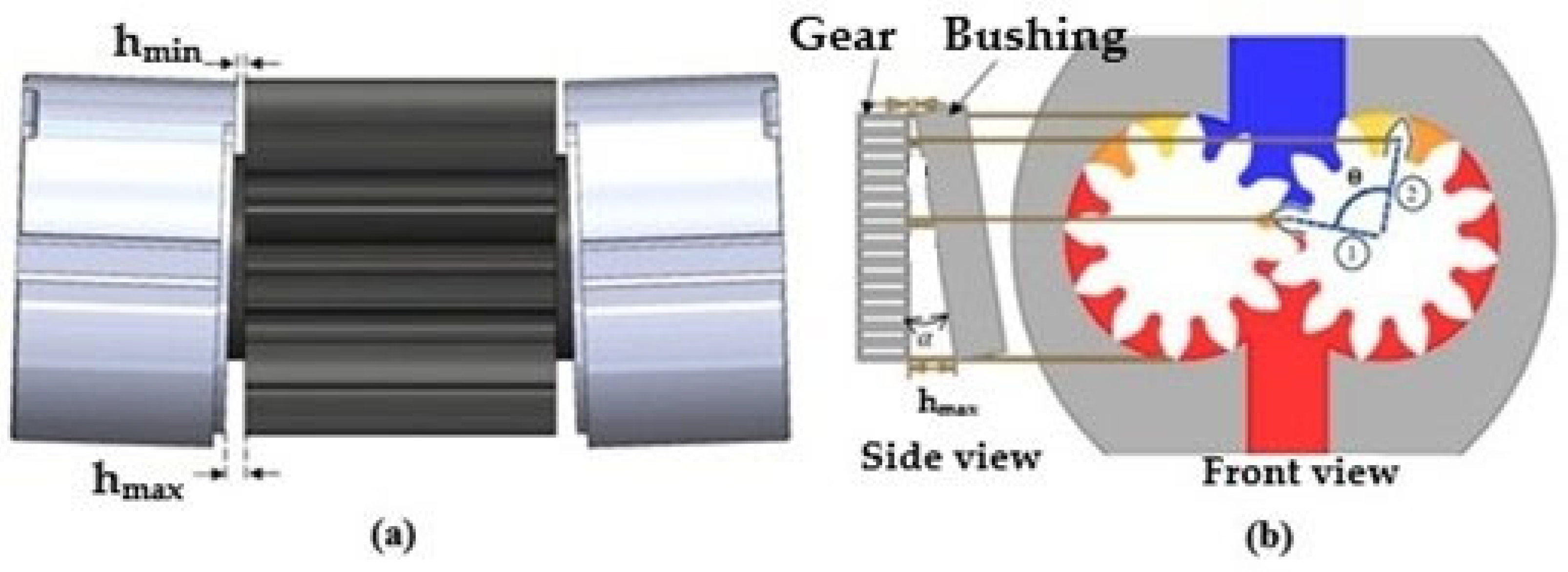
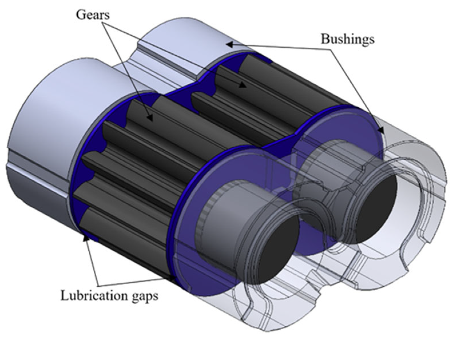
The lateral bushings of an external gear pump,
Figure 1, operate under strongly transient lubrication conditions, particularly on the suction side where the pressure is minimal, and the hydrodynamic film is most sensitive to variations in operating conditions. In this region, the floating bushing is moved toward the gear due to the combined effect of the hydrostatic force imbalance and the tilting moment generated by pressure differences across its surfaces. This motion produces a time-dependent lubrication gap.
As the gear tooth rotates from the meshing zone toward the suction side, covering approximately 90° of angular travel,
Figure 2, the axial clearance between the tooth face and the bushing decreases from its maximum value
hmax to its minimum value
hmin. This reduction occurs within a characteristic time determined by the rotational speed of the pump. The resulting axial convergence induces a squeeze-film effect, which contributes significantly to the hydrodynamic load within the thin film.
To analyze the dynamic behavior of the fluid film, both the sliding motion generated by the gear rotation and the squeezing motion associated with the bushing displacement must be considered. The total hydrodynamic load acting on the bushing can therefore be expressed as a combination of:
a stiffness-related contribution, associated with the sensitivity of the hydrodynamic force to gap height variations;
a damping-related contribution, associated with the fluid resistance to compression during the squeeze motion.
Understanding these dynamic components is essential to characterize the micromotion of the floating bushing and to predict axial stability under real operating conditions.
Figure 2 illustrates the characteristic shape of the lubrication gap and the notation adopted in this study.
2.2. Computational Model
To isolate the tribological behavior of the suction-side lubrication film, a three-dimensional numerical model was developed representing a single tooth and the corresponding portion of the lateral bushing. This approach allows the local flow mechanisms cross-sectional area variations, squeeze-film compression, and texture-induced hydrodynamic effects to be captured with high fidelity while maintaining reasonable computational cost.
As shown in
Figure 2b, the tooth travels from position 1 to position 2 over roughly 90°, during which the gap height decreases by approximately 6 μm. The corresponding time interval is governed by the pump rotational speed. The approaching motion of the bushing relative to the tooth was imposed directly as a boundary displacement, ensuring precise control of the gap-height evolution needed to extract the dynamic coefficients. The computational domain,
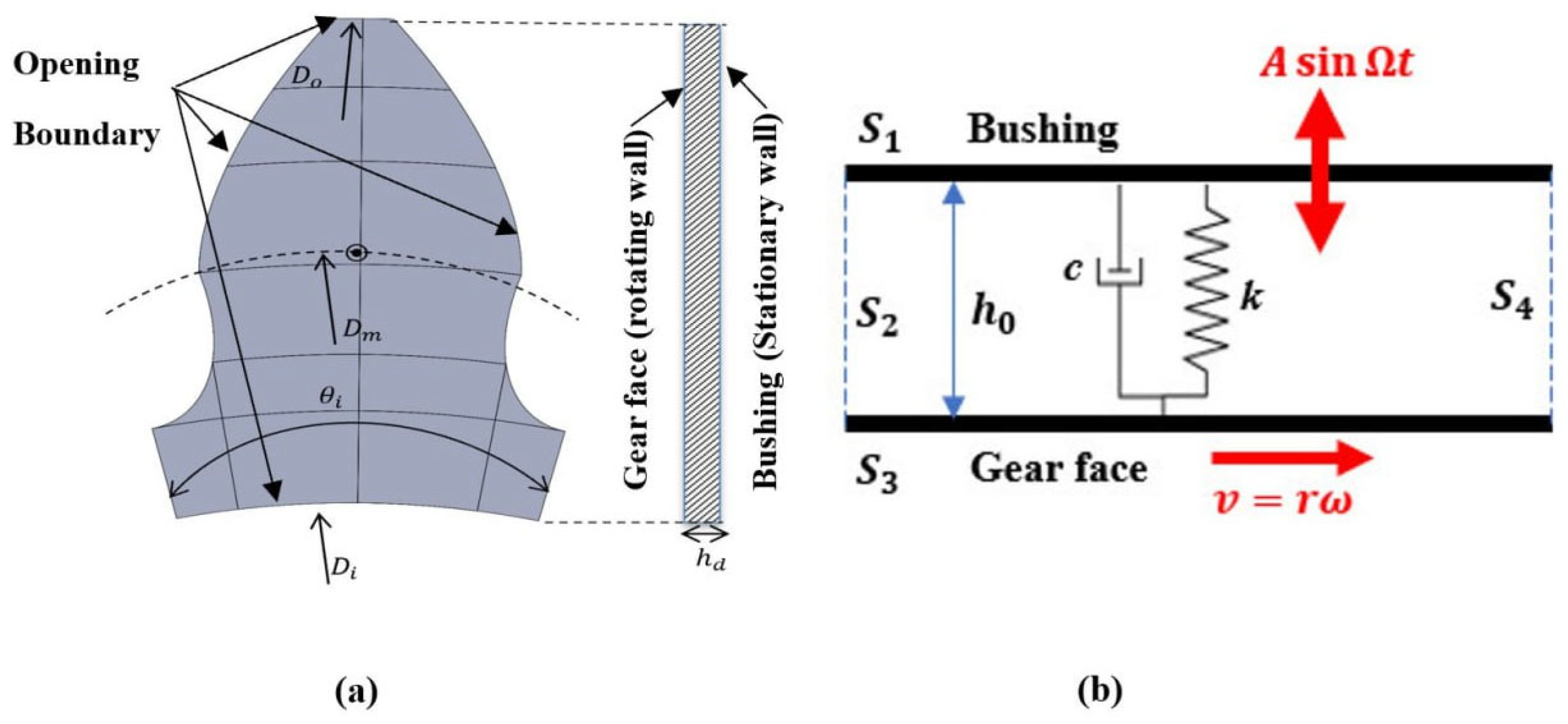
Figure 3a, includes the following:
the rotating gear surface;
the stationary textured (or smooth) bushing surface;
the surrounding fluid region.
The gear rotation generates the sliding velocity component. The bushing axial motion generates the squeezing component. The lubricating oil considered is an ISO VG46 with density ρ = 850 kg/m3 and a dynamic viscosity µ = 0.039 Pas at 50 °C.
Boundary conditions were applied as follows (
Figure 3b):
rotating surface: setting the angular velocity corresponding to the selected operating point ();
bushing surface: setting the time-dependent axial motion (;
side openings: pressure-outlet condition with 1 bar absolute pressure, appropriate for the suction side ().
This setup enables direct computation of the instantaneous hydrodynamic force, which is the key variable used to derive stiffness and damping coefficients.
The geometric and operating parameters of the simulation model are presented in
Table 1.
2.3. Governing Equations
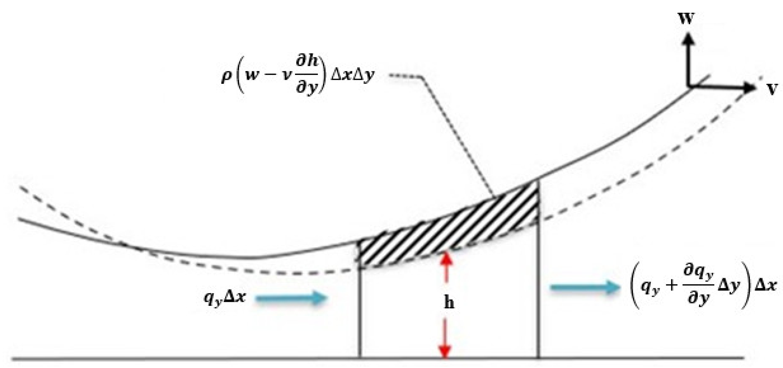
The lubrication behavior is governed by the three-dimensional incompressible Reynolds equation, which describes pressure generation in thin films subjected to sliding and squeezing motions. Referring to
Figure 4, the sliding velocity in the
y-direction is denoted by
v. The general form of the Reynolds equation is as follows:
Since density variations remain below 0.5% under the operating conditions of the suction side, the lubricant is treated as incompressible (
ρ = const); for rigid surfaces, the stretching terms vanish, leading to the simplified form:
The squeeze velocity in the
z-direction is as follows:
This equation is solved numerically using ANSYS CFX (2024), which computes the instantaneous pressure field and resulting hydrodynamic force W(t), by integrating the computed fluid gap pressure over the tooth surface.
2.4. Extraction of Stiffness and Damping Coefficients
This paper is focused on the evaluation of the stiffness and damping coefficients of the lubrication gap with reference to the bushing and the single tooth considered. The goal is to characterize the dynamic behavior of the textured design considered.
The total load comes from a linear superposition of a spring and a damper:
where
W0 is the static load, while the term
Wd is the dynamic load equal to:
where
w is the gap height variation versus time, the squeezing velocity defined in Equation (3). The static load
W0 is the static force at the beginning of the simulation and considered as zero.
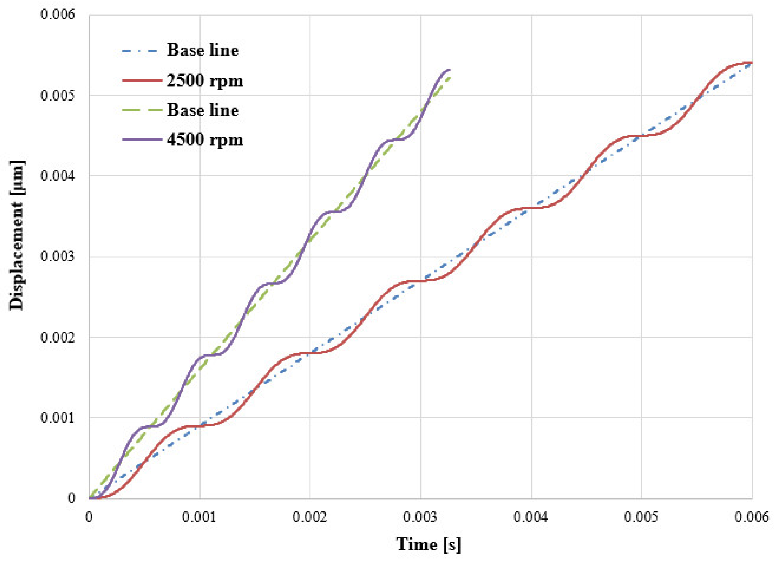
To reproduce the micromotion of the floating bushing caused by fluctuating pressure forces, a harmonic perturbation was added to the nominal approaching motion:
The approaching speed remains in the same direction; therefore, the gap height never increases but always decreases (
Figure 5); in other words, the first derivative of the speed with respect to time is always positive.
In Equation (6) the frequency
has been computed based on data in
Table 2.
Different simulations were carried out with different values of the micromotion frequency that are mainly associated with different rotational speeds of the pump (
Table 2).
The values reported in
Table 2 for the typical frequencies have been obtained considering the number of teeth of the two gears.
2.5. Stiffness Coefficient
The hydrodynamic stiffness represents the sensitivity of the load to variations in gap height:
To determine k(h), a series of steady-state CFD simulations were performed at fixed gap heights spanning from hmax to hmin, while maintaining the sliding velocity corresponding to the reference rotational speed.
The numerical procedure is based on the definition of the stiffness coefficient versus the gap height based on Equation (7):
To determine the consecutive values of the load in Equation (8), a gap-height step of 0.5 μm was considered.
It should be noted that, for the stiffness calculation, only the sliding velocity was considered.
2.6. Damping Coefficient
The damping coefficient quantifies the resistive force generated by fluid squeeze-film action versus approaching velocity:
The numerical procedure is based on the following Equation (10):
An average damping coefficient has also been computed based on this Equation (11):
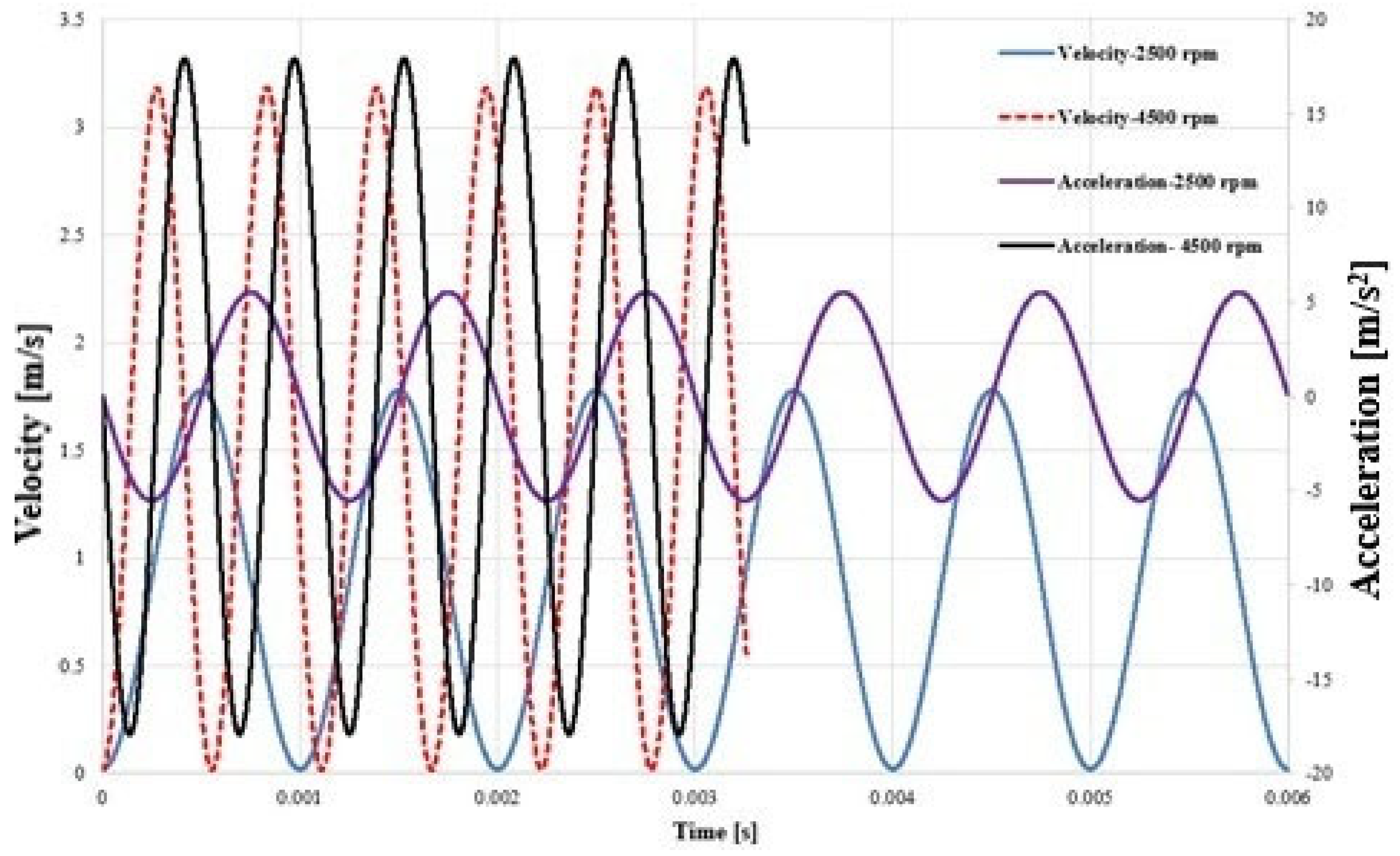
From Equation (6) the instantaneous velocity and acceleration of the floating bushing has been easily computed:
The imposed velocity and acceleration functions for two different rotational speeds are shown in
Figure 6.
In
Figure 6 the velocity can reach values close to zero, but it is always positive, and gap height continuously reduces its value, but obviously the acceleration is not constant because of the velocity variation versus time assumed.
It should be noted that the imposed displacement law corresponds to a continuously decreasing gap height, and the squeeze velocity remains strictly positive throughout the simulated interval. Therefore, no separating phase occurs, and the lubrication film remains in a full-film hydrodynamic regime. Under these conditions, local pressure does not drop below vapor pressure and cavitation is not triggered.
Filtering Condition
The instantaneous damping coefficient was evaluated from the CFD results using a finite-difference approximation, as reported in Equation (10); the computation results are a function of time, and Equation (10) can be rewritten as Equation (13):
This expression becomes ill-conditioned when the change in velocity is very small and close to zero (
Figure 6), and it amplifies numerical noise. To obtain a physically meaningful estimate of the film damping, the data were filtered by setting a threshold on the instantaneous acceleration
:
samples with were discarded;
the remaining samples were split into the following two sets: a () m/s2 (increasing squeeze velocity) and a () < − m/s2 (decreasing squeeze velocity).
The adopted threshold values of positive and negative accelerations have been obtained to avoid numerical overflow; as a matter of fact, when the acceleration is very low and approaches zero, the corresponding velocity variation between adjacent time steps becomes very small, making the evaluation of the damping coefficient not reliable (Equation (13)).
For each set, local negative values of D() could be found; as a matter of fact, when the velocity also decreases, the pressure and the load decrease, but this process presents a physical delay that generates a negative variation in the speed (denominator Equation (13)) while the load variation remains yet positive (numerator of Equation (13)). Negative values of damping coefficient have been avoided managing the numerical interval considered.
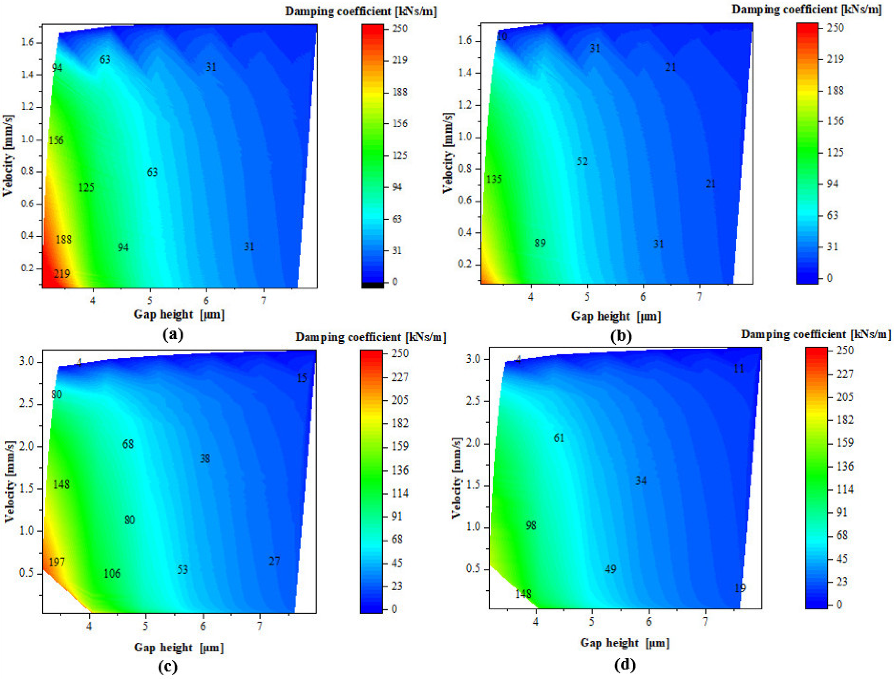
The damping coefficient has been computed as a function of instantaneous gap height and squeeze velocity; to present a clear scenario of its variation, contour maps have been generated for all the cases considered.
2.7. Grid Independence Study and Simulation Setup
To ensure that the CFD predictions are not influenced by the spatial discretization, a dedicated grid-independence analysis was carried out. The starting point was a structured mesh generated with a nominal element size of 0.02 mm in the lubrication gap region, which was identified as the most critical area for resolving pressure and velocity gradients. Particular attention was paid to the number of elements stacked across the film thickness, since this directly controls the resolution of the shear layer and the squeeze-induced pressure variations.
A sequence of meshes was constructed by varying the number of layers across the gap, while keeping the in-plane element size unchanged. Four configurations were examined, with 4, 7, 9 and 11 layers in the gap direction, respectively (
Table 3). Because the gap is compressed during the approaching motion, the layer count has a strong impact on how finely the film is sampled at the minimum clearance, and thus on the accuracy of the computed hydrodynamic force.
The resulting total reaction force on the gear was normalized with respect to the value obtained with the nine-layer mesh, which is taken as the reference case. Moving from 9 to 11 layers changes the normalized force by only about 2%, whereas the seven-layer mesh differs by roughly 5% from the reference and the coarse four-layer mesh underestimates the force by more than 25%. At the same time, the force and the overall flow pattern remain essentially unchanged between the 9 and 11 layer meshes, indicating that further refinement provides marginal benefits at a significantly higher computational cost. The meshes were generated using a sweep strategy that produces purely hexahedral elements throughout the thin gap and over the textured bushing surface. Inflation layers were introduced at solid boundaries to accurately resolve steep velocity gradients and wall shear stresses within the micrometric film thickness. Standard mesh-quality indicators (skewness and aspect ratio) were monitored and remained within recommended limits for all configurations.
Considering the balance between accuracy and computational effort, the grid with nine layers in the lubrication gap was adopted for all subsequent simulations. This mesh provides a good compromise, with force predictions very close to the finest grid and sufficient resolution of the local flow structures in and around the dimples.
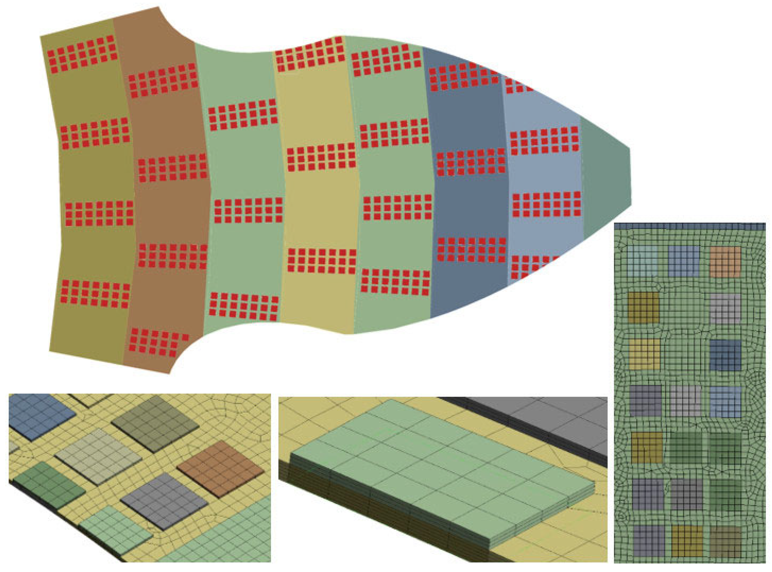
Based on the analysis of accuracy, flow resolution, and computational cost, the nine-layer mesh was selected as the final configuration. The resulting mesh structure (for the three-line dimple) is illustrated in
Figure 7.
The transient simulations were performed using a second-order implicit time-integration scheme with adaptive time stepping. The Courant number was constrained within the range 0.9–0.95 to ensure stable and well-resolved transient behaviors. For the 1000 Hz excitation, a nominal time step of 1 × 10⁻⁵ s was used (100 points per period), while for 1800 Hz a time step of 5 × 10⁻⁶ s was adopted (approximately 111 points per period). These values ensure accurate reconstruction of force amplitude and phase lag with negligible numerical dissipation.
The flow was modeled as laminar throughout the computational domain. No turbulence model (RANS or LES) was employed. The validity of this assumption was verified by estimating the local Reynolds number in the lubricating film using = 850 kg/m3 and μ = 0.039 Pa·s at 50 °C. For the most demanding operating condition (4500 rpm), assuming a conservative upper bound of U ≈ 18 m/s and maximum clearance h = 5 μm, the resulting Reynolds number is Re ≈ 1.96. For h = 3 μm, Re ≈ 1.17. Therefore, the flow remains in the viscous dominated across the entire investigated clearance range. Even considering locally increased velocities inside the texture pits, the Reynolds number remains well below transitional values.
Global mass conservation was monitored during all simulations. A conservation target of 0.01 (in ANSYS CFX, the conservation target is a numerical convergence control that monitors how well the solver satisfies global conservation laws, mainly mass conservation (continuity) across the computational domain [
36]) was imposed in ANSYS CFX to control the global mass imbalance, and all cases satisfied this criterion. Given the micrometric film thickness and the sector-based computational domain, the volumetric flow rate through the gap is small and not a primary focus of the present study; however, strict mass conservation was maintained in all operating conditions.
3. Results and Discussion
This section presents the main numerical results of the CFD simulations, focusing on the evaluation of the stiffness and damping coefficients of the lubrication gap between the bushing and the gear tooth. Following the approach adopted in the previous work [
34], two different texturing configurations are considered to assess the influence of surface texturing on these coefficients. First, the pressure evolution in the squeezing film is briefly discussed. Then, the static force–gap height relationship and the corresponding stiffness are analyzed. Finally, transient simulations with perturbed approaching velocities are used to extract the damping coefficient and to quantify the impact of surface texturing on the dynamic behavior of the lubrication film.
3.1. Pressure Evolution in the Lubrication Gap
The pressure field generated in the lubrication gap plays a central role in determining both the static load capacity and the dynamic response of the bushing–gear interface. As the gap height decreases and the sliding velocity increases, the combined sliding–squeezing mechanism produces a strongly a time-dependent pressure distribution. Understanding how texture geometry modifies this distribution is essential for interpreting the stiffness and damping trends discussed in the subsequent sections.
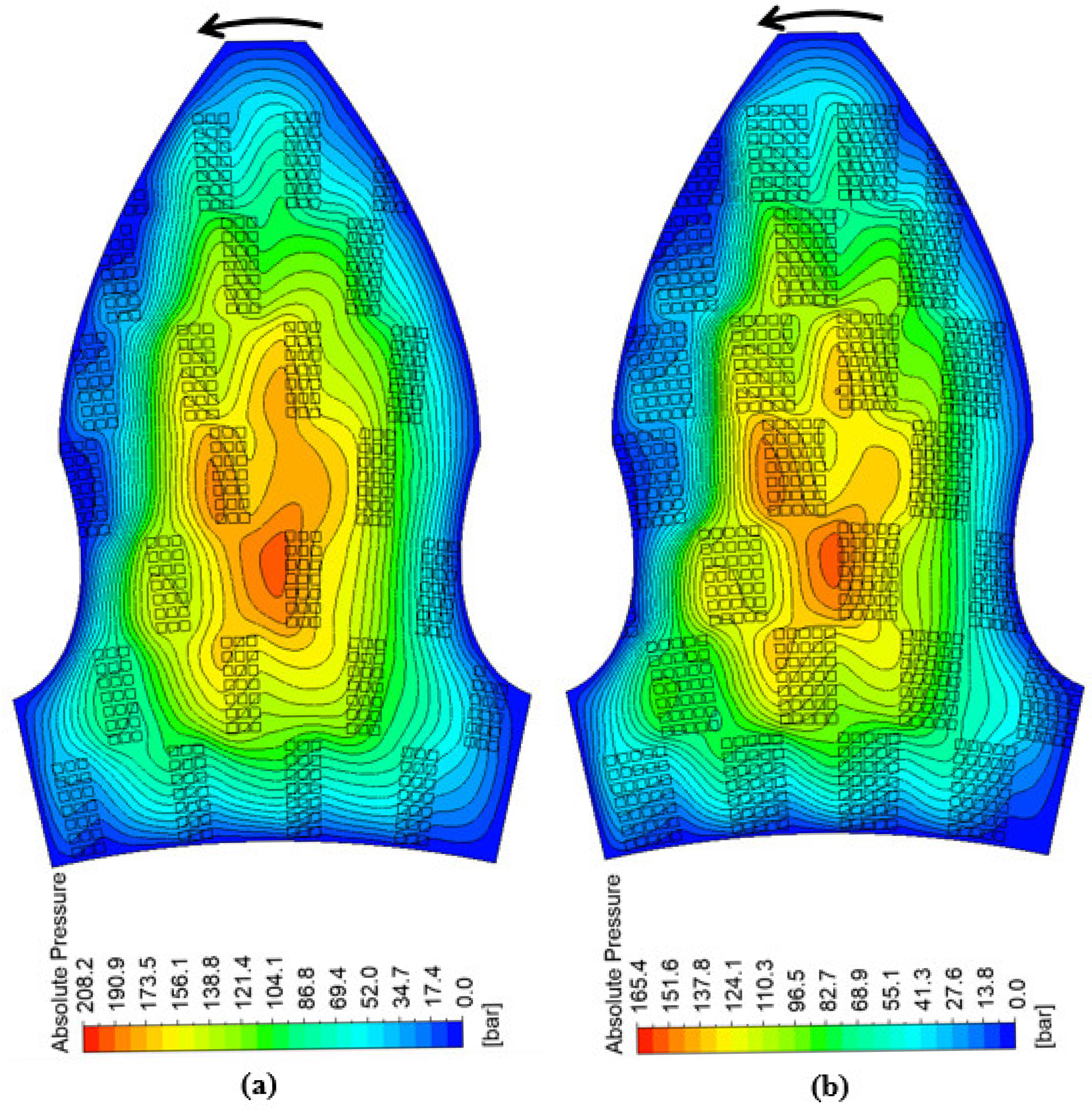
Figure 8 shows the pressure field in the lubrication gap for a representative gap height of 3.5 µm at a rotational speed of 2500 rpm, comparing the two texturing configurations. In both cases, the pressure distribution is governed by the interaction of sliding motion and squeeze-film compression. However, the presence and arrangement of dimples noticeably modify the pressure distribution within the thin film.
In both configurations shown in
Figure 8, the pressure increases along the sliding direction and reaches its maximum in the converging region of the film, corresponding to the untextured portion of the surface. For both cases, the highest pressures are located near the central region of the gear, where fluid escape is more limited and part of the lubricant becomes locally trapped between the dimples, thereby enhancing load support. However, the peak pressure in case (b) is lower than in case (a). This indicates that increasing the textured area leads to a slightly larger effective gap height and, consequently, to a reduction in the load-carrying capacity of the lubrication film.
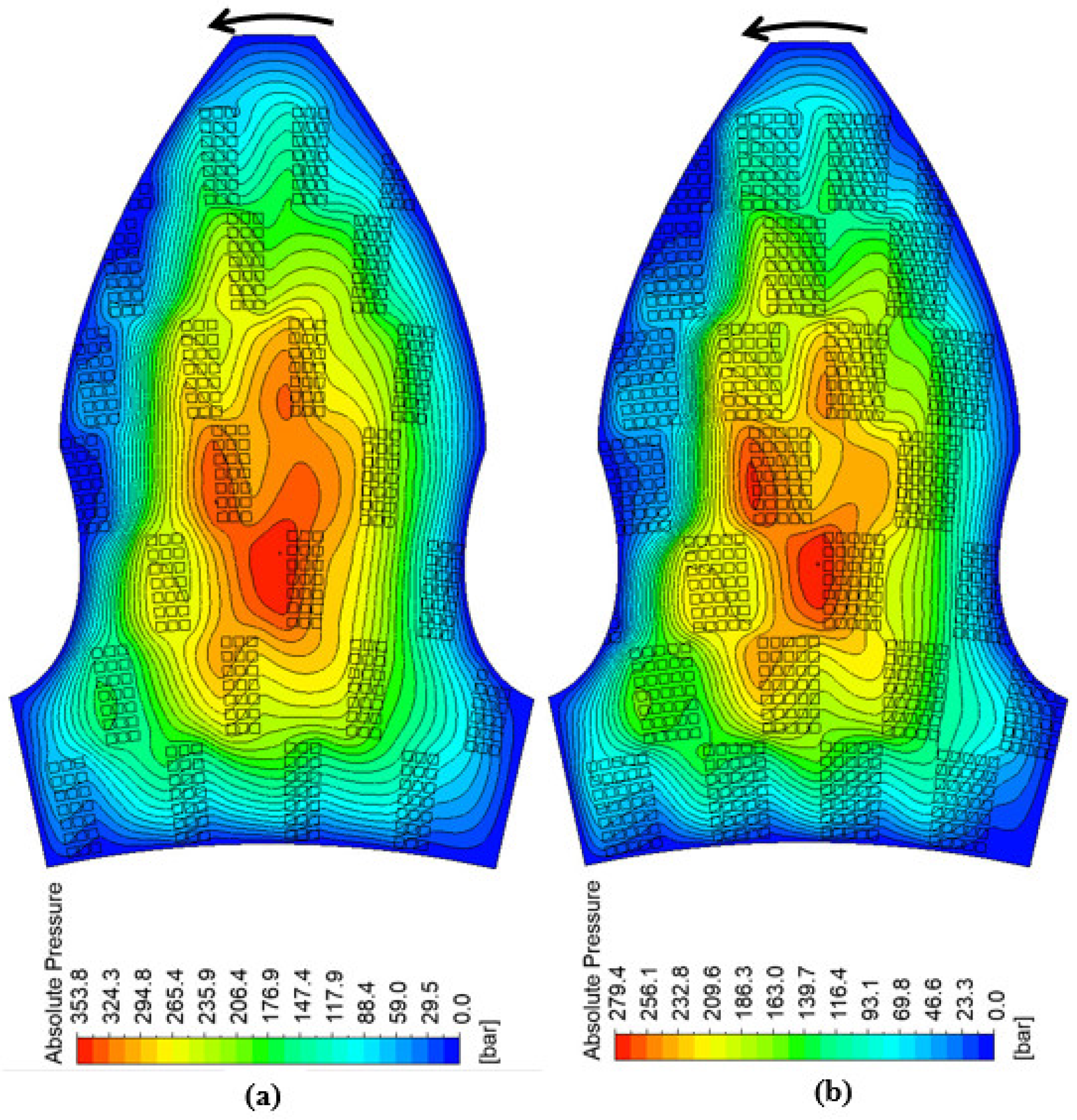
Figure 9 reports the corresponding pressure distributions at 4500 rpm.
As expected, the increase in rotational speed enhances the shear-driven contribution to pressure generation and raises the overall pressure level in the gap. In both configurations shown in
Figure 9, increasing the rotational speed from 2500 to 4500 rpm enhances the pressure level in the lubrication gap. The main features observed at 2500 rpm are preserved, with a noticeable pressurized region in the converging part of the film and peak values located near the central portion of the gear. However, the contrast between low- and high-pressure zones becomes sharper at the higher speed. In the three-line configuration, the pressurized area expands while remaining relatively smooth, whereas in the five-line pattern stronger local peaks appear near the dimple exits, slightly shifted in the direction of rotation due to the higher sliding velocity. These observations confirm that texture density and operating speed jointly control the intensity and distribution of the pressure field, with direct implications for the effective stiffness and damping characteristics discussed in
Section 3.2 and
Section 3.3. To further illustrate the flow structure within the lubrication gap,
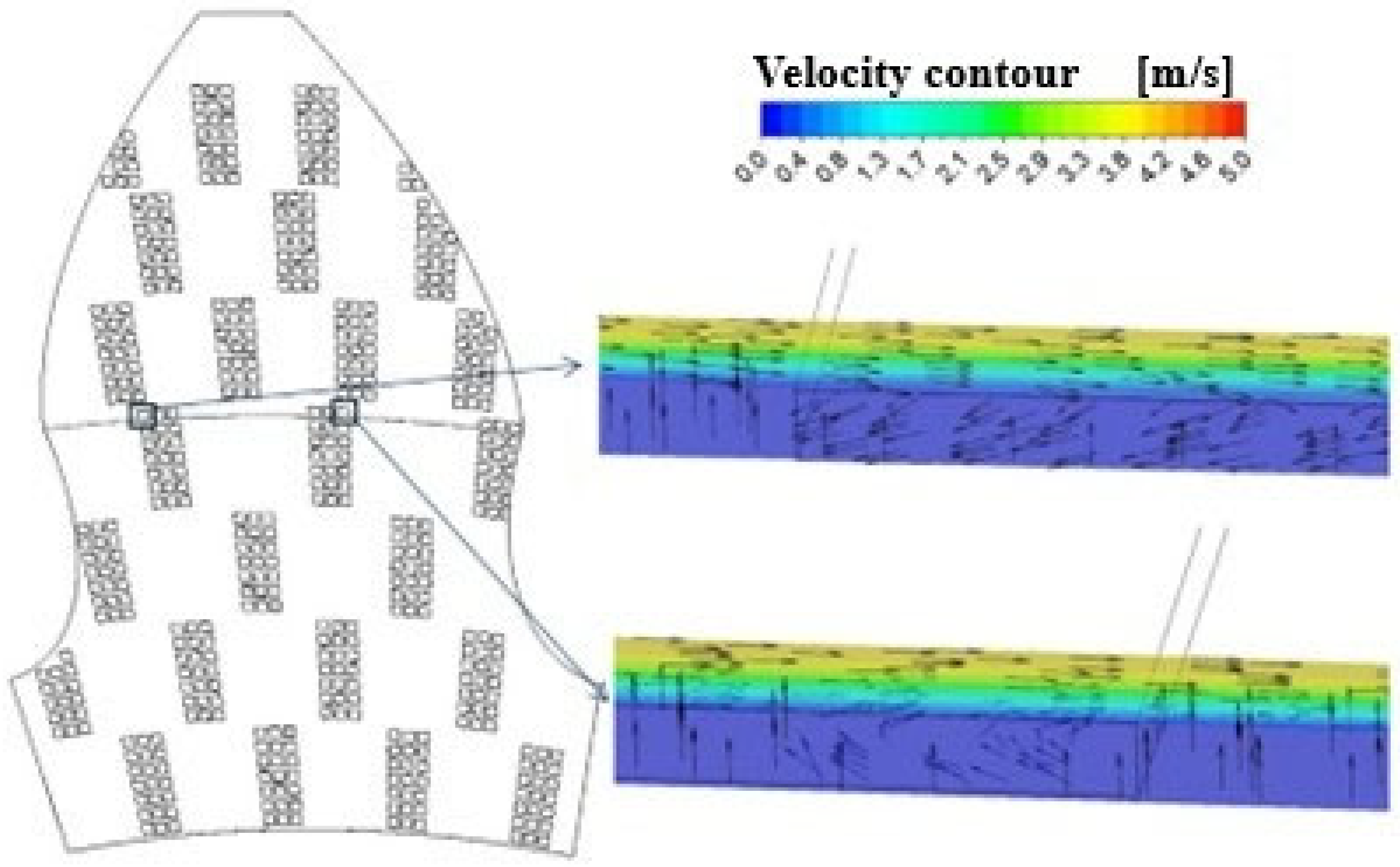
Figure 10 presents the velocity vectors and velocity magnitude contours in representative cross-sections of the textured interface when the rotational speed is 2500 rpm.
The velocity distribution shows the expected Couette-type profile across the film thickness, with maximum velocity occurring at the rotating gear surface and approaching zero at the stationary bushing wall. In addition to the shear-driven motion, the closing gap generates a squeeze-flow component as the bushing wall moves toward the gear surface. This effect is visible in the vector field as vertical velocity vectors directed across the film thickness. Inside the dimples, the interaction between the main shear flow and the cavity geometry leads to the formation of local vortical structures. These recirculation zones contribute to local pressure redistribution and influence the hydrodynamic response of the textured surface.
3.2. Static Force–Gap Height Relationship and Stiffness
The static hydrodynamic load as a function of the gap height
h was obtained from a series of steady-state simulations performed at different clearances, while maintaining the sliding velocity corresponding to the reference rotational speed.
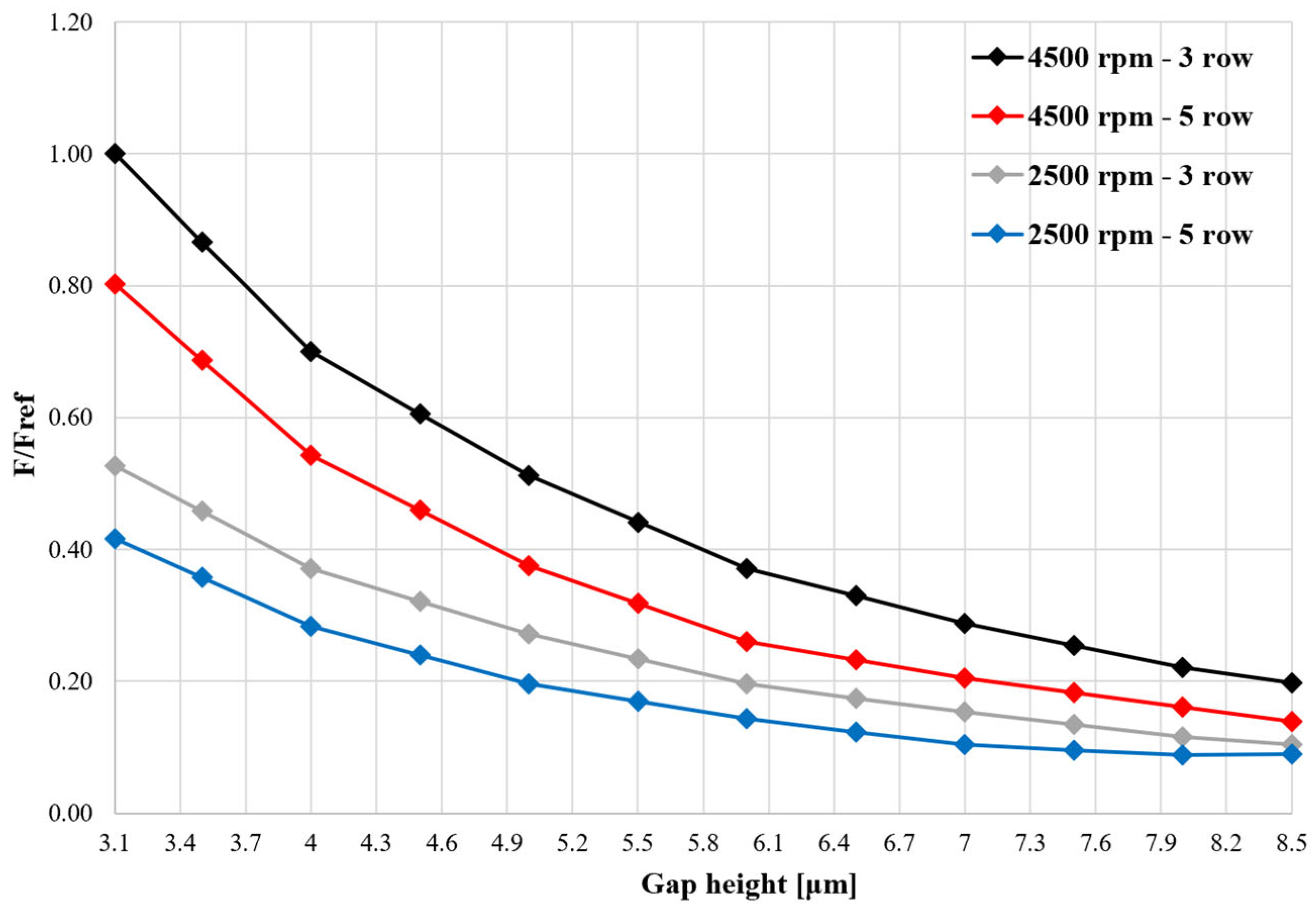
Figure 11 reports the static hydrodynamic force as a function of the gap height for the reference operating condition; for confidentiality reasons the force was normalized with respect to the maximum value. As expected, the load decreases monotonically with increasing clearance. Increasing the rotational speed leads to higher Couette-induced pressure and, consequently, to a larger hydrodynamic force. In addition, when the number of dimples is increased, the effective/average gap height becomes slightly larger, which reduces the pressure level and therefore the resulting load-carrying capacity.
The curves present a progressive steepening as the gap approaches the minimum value. For gap heights larger than roughly 6.5 μm, the force varies relatively slowly with clearance, indicating that the lubrication film provides only a modest supporting action when the bushing is far from the gear. In contrast, for gap heights below about 5 μm, a small additional reduction in clearance results in a marked increase in load, revealing the strong sensitivity of the suction-side film in the small-gap regime.
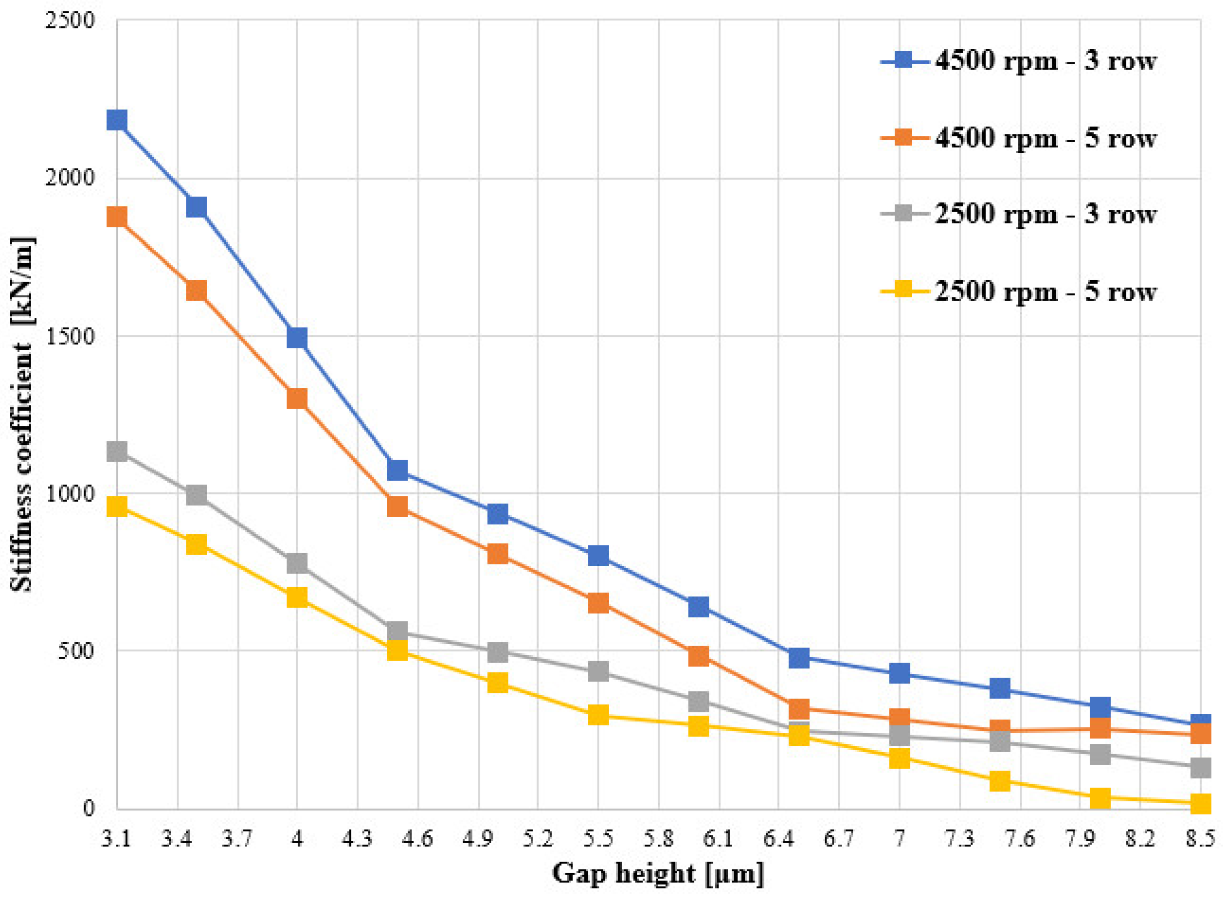
The corresponding stiffness coefficient, obtained by numerical differentiation of this curve, is shown in
Figure 12.
Figure 12 shows that the stiffness coefficient increases markedly as the gap height is reduced from its maximum to its minimum value. This trend reflects the stronger confinement of the lubricant in thinner films, which enhances the pressure build-up and, consequently, the normal reaction on the surface. Since the stiffness is defined as the derivative of the load with respect to the gap height, this steeper force–height relationship at smaller clearances translates into a noticeable increase in stiffness as the gap closes, confirming the highly nonlinear spring-like behavior of the lubrication film.
From a design perspective, these results highlight that the suction-side lubrication film provides the most effective restoring action when the bushing operates close to the minimum clearance, which is also the condition where the risk of mixed lubrication and surface damage is higher. The stiffness coefficient derived from
Figure 12 therefore represents a key input for subsequent dynamic models aimed at predicting the axial stability of the floating bushing.
3.3. Transient Response Under Perturbed Approaching Motion
To characterize the damping behavior of the lubrication film, a transient simulation was carried out in which the nominal approaching motion of the bushing was superimposed with a harmonic perturbation. This displacement law produces anyway a constantly decreasing gap height, from 8.5 to 3.1 μm, while the squeezing velocity oscillates around a mean value, as described in
Section 2.4.
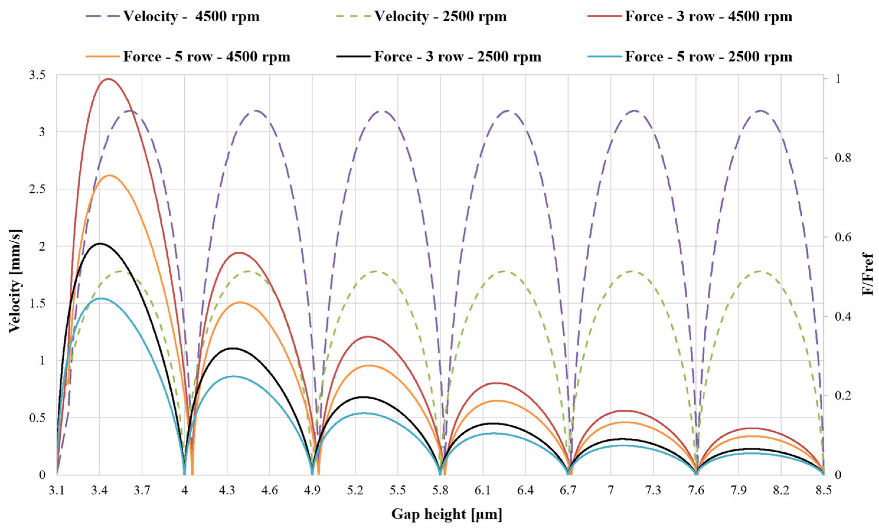
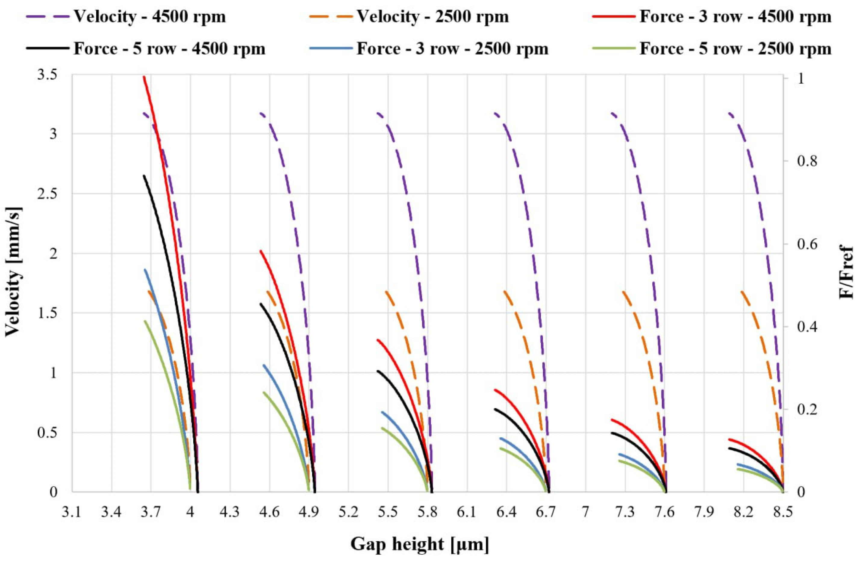
Figure 13 shows the evolution of the squeezing velocity and the corresponding transient hydrodynamic force plotted as functions of the instantaneous gap height for different rotational speed and texturing configurations. It should not be like that; transient force has been normalized to the maximum transient force value.
Figure 13 shows the transient hydrodynamic force extracted from the CFD simulations together with the corresponding squeezing velocity, both plotted as functions of the instantaneous gap height. The velocity remains strictly positive, confirming that the gap continuously closes, and exhibits six noticeable oscillations along the trajectory. The associated force signal follows the same overall trend as the static force–height curve, with higher values at smaller clearances, but it is modulated by the perturbation: local peaks of velocity correspond to local increases in transient force, especially in the intermediate-gap region. A slight phase delay between the two curves can be observed, reflecting the finite response time of the lubrication film to rapid variations in the squeezing motion. Where the velocity approaches zero (around h ≈ 4.1 and 6.7 μm), the force does not vanish, indicating the finite hydrodynamic stiffness of the film even in the absence of instantaneous squeeze. Increasing the rotational speed, and thus the approaching velocity, amplifies the force levels, with this effect becoming particularly evident at the smallest gap heights, where fluid confinement is strongest.
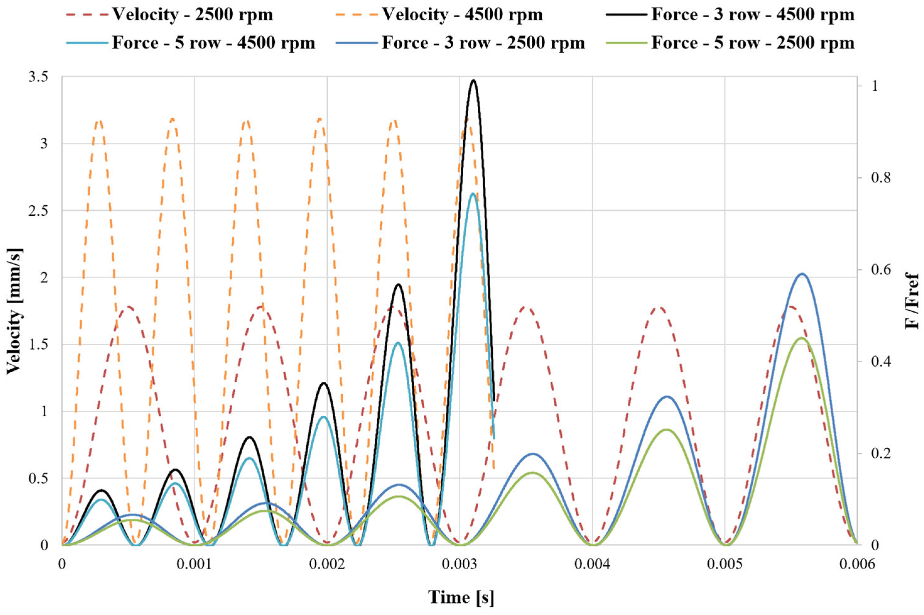
Velocity and normalized force courses are reported in
Figure 14 as a function of time. The squeezing velocity exhibits a nearly sinusoidal evolution with six complete cycles over the simulated interval, while the transient force oscillates with a clear phase lag relative to the velocity.
This phase shift indicates the dissipative nature of the fluid film: the hydrodynamic load does not respond instantaneously to changes in velocity but reacts with a delay, which is directly related to the damping characteristics of the gap. In addition, the amplitude of the force oscillation increases as time progresses, due to the concurrent reduction in the gap height; the film becomes progressively stiffer and more dissipative as the bushing moves closer to the gear. The instantaneous force and velocity obtained from these simulations were used to compute the instantaneous damping coefficient.
3.4. Damping Coefficient Maps for Positive and Negative Acceleration
After applying the acceleration-based filtering described in
Section 2.4, two distinct datasets were obtained. The first corresponds to positive acceleration (a > 2 m/s
2), where the squeezing velocity increases.
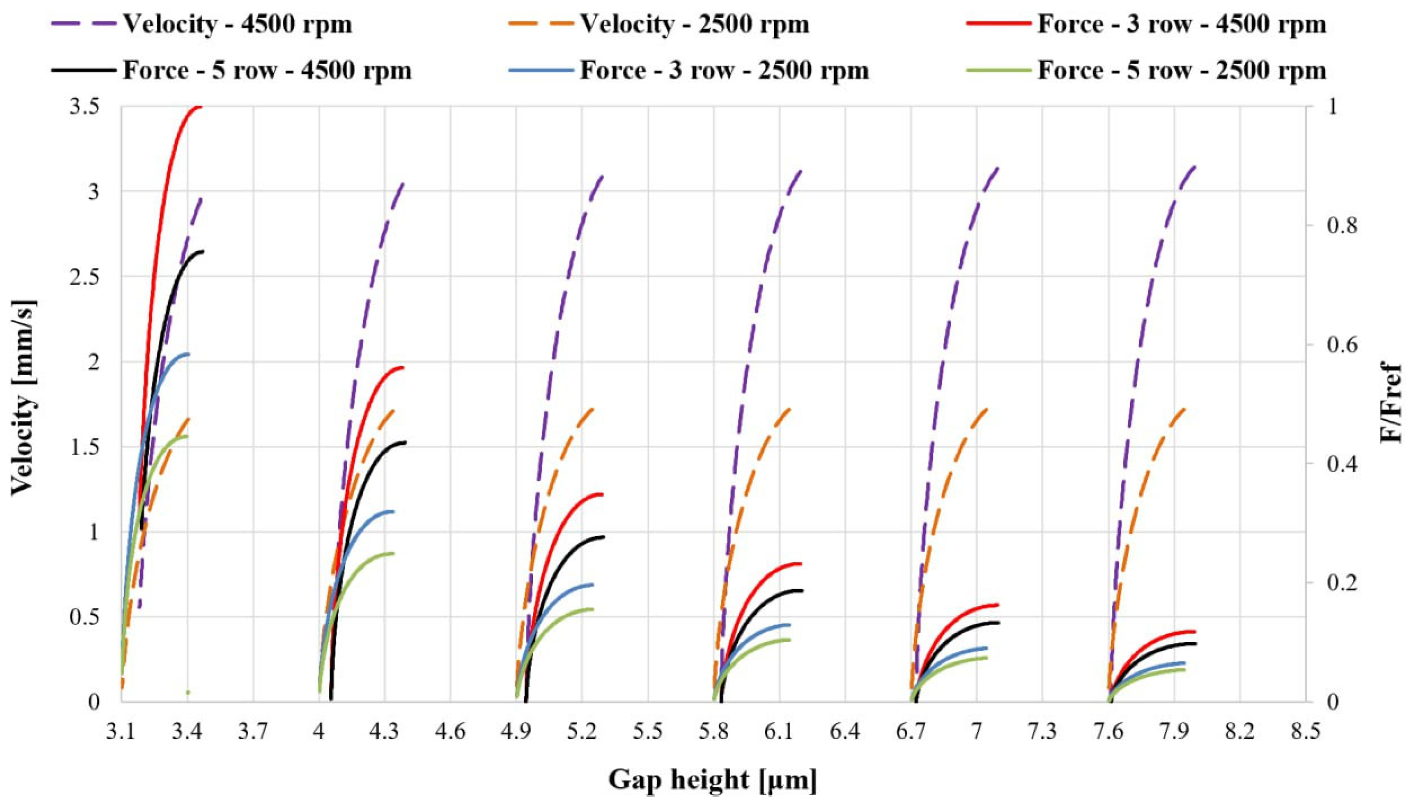
Figure 15 shows the filtered normalized force and velocity signals for this condition.
As expected, only the portions of the trajectory where the velocity accelerates are retained, resulting in a uniformly increasing velocity profile for each cycle.
The second dataset corresponds to negative acceleration (a < −2 m/s
2), where the squeezing velocity decreases. The filtered normalized force and velocity associated with this regime are shown in
Figure 16. In this case, the velocity gradually decreases within each oscillation, while the force still increases as the gap height is reduced, consistent with the strong pressure build-up in the thin-film region.
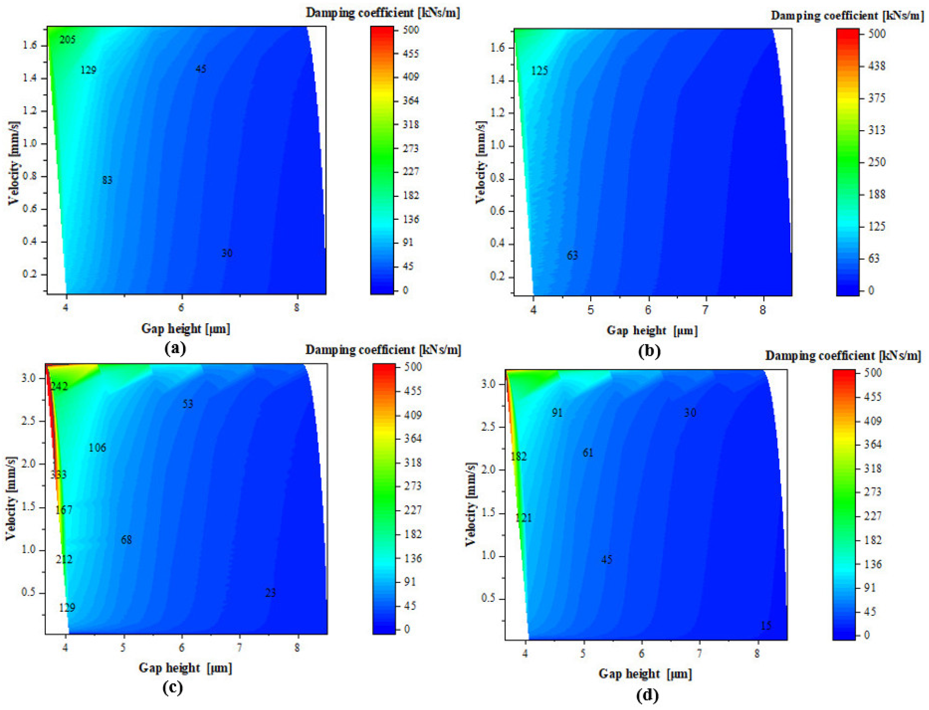
For each dataset, only positive values of the instantaneous damping coefficient were retained, and the filtered points were interpolated to generate two-dimensional maps of D (h, v).
Figure 17 reports the corresponding damping map for a > 2 m/s
2 (accelerating squeeze motion).
Figure 17 presents the damping coefficient maps for the positive-acceleration regime. The damping coefficient increases markedly as the gap height is reduced, reflecting the stronger confinement of the lubricant in the thin film. In this regime, the pressure field can respond progressively to the increasing squeeze motion, and the resulting force variations depend on how rapidly the velocity changes. Higher damping values are obtained when force variations occur over relatively small velocity changes, while larger velocity variations lead to lower damping coefficients (Equation (13)). Increasing the textured area slightly enlarges the effective gap height, reducing pressure build-up and therefore decreasing the damping coefficient.
Figure 18 shows the damping coefficient maps for the negative-acceleration regime. In this condition, the lubricant pressure does not immediately adapt to the reduction in velocity, leading to a delayed hydrodynamic response and enhanced resistance to motion. The highest damping values occur in the small-gap region, where strong geometric confinement increase sustained pressure build-up during deceleration. Increasing rotational speed results in larger hydrodynamic force levels, which translate into higher damping coefficients through the force velocity formulation (Equation (13)). At larger gap heights, where confinement is weaker, the damping decreases and the influence of operating speed becomes less important.
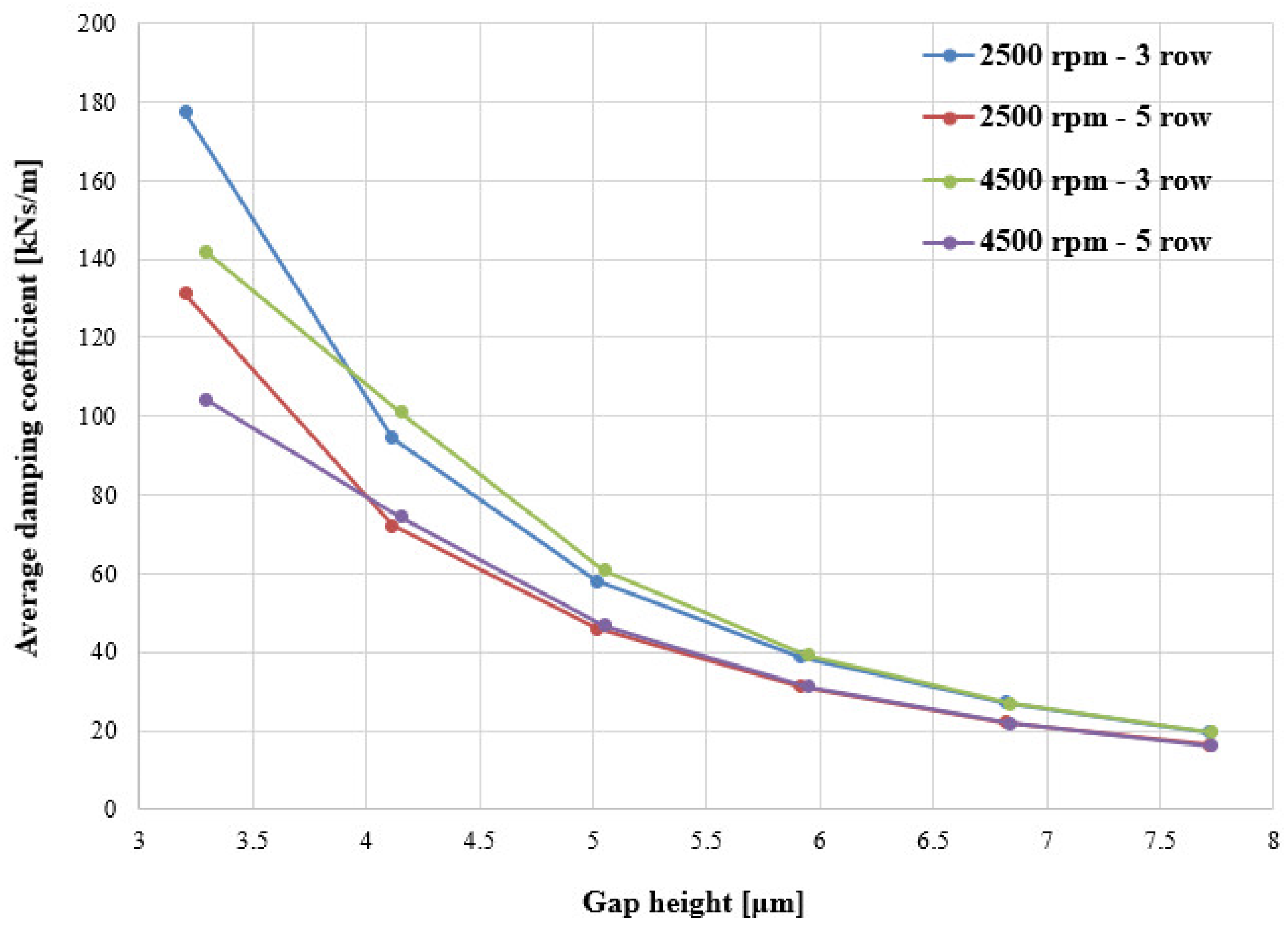
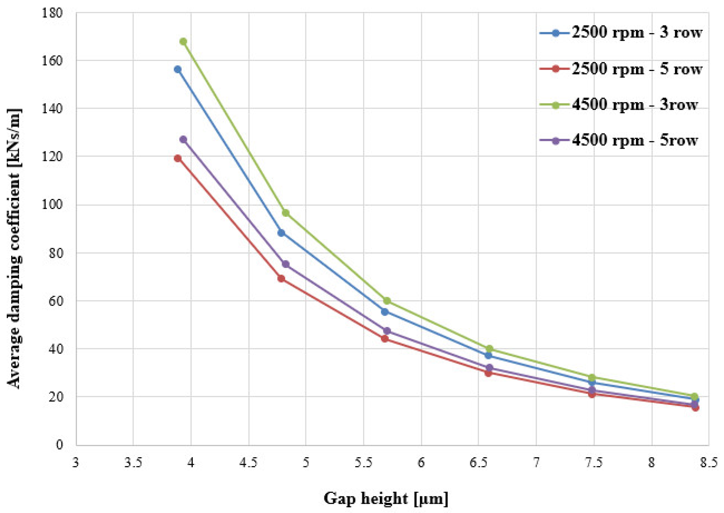
To better quantify these trends, the instantaneous damping values extracted from the transient simulations were averaged over narrow gap-height intervals. In the following, the resulting average damping coefficients are presented as functions of the gap height and operating condition, providing a more compact and design-oriented representation of the lubrication gap damping coefficients. The values shown are obtained by averaging instantaneous damping coefficients over successive gap-height intervals.
Figure 19 reports the average damping coefficient as a function of gap height for positive acceleration (a > 2 m/s
2). In all cases, damping increases as the clearance decreases, highlighting the dominant squeeze-film behavior of the lubrication gap.
Figure 20 reports the average damping coefficient as a function of gap height for the subset of data corresponding to negative acceleration (a < −2 m/s
2). As in the positive-acceleration regime, the damping increases markedly as the clearance is reduced, with the highest values occurring in the small-gap region due to strong squeeze-film confinement.
In both cases for a given gap height, the three-row textured configuration consistently provides higher damping than the corresponding five-row case, indicating a stronger viscous resistance to the squeeze motion.
The comparison between the two acceleration trend results confirms that the suction-side film behaves as a nonlinear damper whose characteristics depend not only on the instantaneous gap height and velocity, but also on the sign of the acceleration, i.e., whether the squeeze motion is speeding up or slowing down. This information is particularly important for developing lumped parameter models of EGP with textured bushings.
The stiffness and damping maps presented in this work represent the dynamic response of the lubrication gap in the absence of cavitation. The influence of multiphase cavitation modeling on the extracted dynamic coefficients will be investigated in future work.
4. Conclusions
This work presents a detailed CFD-based investigation of the dynamic behavior of the suction-side lubrication gap between the lateral bushing and the gear tooth in external gear pumps, with particular focus on the effects of surface texturing and bushing micromotion. By combining steady-state force–gap height simulations with transient perturbation analyses, the study quantifies the effective stiffness and damping generated by the coupled sliding–squeezing flow in this highly transient lubrication region. The results show that hydrodynamic stiffness increases sharply as the gap height decreases, revealing a strongly nonlinear spring-like response of the lubrication film and an increased sensitivity to minimum-clearance operation. Surface texturing modifies these trends in a non-trivial way as follows: increasing the textured area slightly enlarges the effective gap height and reduces peak hydrodynamic pressures, leading to a decrease in load-carrying capacity as well as in the associated stiffness and damping coefficients. These findings indicate that excessive texturing may weaken the dynamic support provided by the lubrication film. Consequently, the selection of an appropriate texturing configuration becomes a key design parameter, requiring a balance between the tribological benefits of dimples and the need to preserve sufficient stiffness and damping for axial stability. The transient analyses further show that the damping behavior strongly depends on rotational speed, gap height, squeeze velocity, and acceleration regime. The smallest gaps exhibit the highest damping levels, while the damping distribution differs significantly between accelerating and decelerating squeeze motions. These results demonstrate that the lubrication film behaves as a nonlinear, acceleration-dependent damper whose characteristics cannot be accurately described using conventional quasi-static or linearized approaches. Overall, this study provides a dynamic characterization of textured suction-side lubrication films in external gear pumps and establishes a CFD-based framework for evaluating stiffness and damping in complex sector-like lubrication geometries. The resulting stiffness and damping maps, together with the identified influence of texture density, can support the development of lumped-parameter models and guide the design of surface-textured bushings aimed at improving axial stability, reducing wear, and enhancing pump performance.
Although direct experimental validation at the film level is not feasible due to the micrometric clearance, the numerical predictions are consistent with previously reported experimental trends in pump performance for textured and non-textured bushings. In particular, the simulated force and flow variations follow physically expected scaling with clearance and rotational speed, and global mass conservation is satisfied in all cases. The results should therefore be interpreted as a numerically verified and physically consistent characterization of the full-film hydrodynamic regime within the investigated operating conditions.