1. Introduction
The performance of high-precision industrial motion control systems critically determines the quality and efficiency of high-end equipment manufacturing. Within such systems, dynamic load disturbances, nonlinear parameter coupling, and synchronization accuracy degradation among multiple actuation units represent persistent core challenges. As a typical precision roll-to-roll manufacturing process, the control of printing pressure in flexographic printing is paramount to print quality. This pressure directly affects the accuracy and uniformity of pattern transfer from the printing plate to the substrate. Since flexographic printing employs highly elastic photopolymer plates, it is extremely sensitive to pressure fluctuations: insufficient pressure causes incomplete ink transfer, while excessive pressure leads to dot gain, accelerated plate wear, and even substrate damage. Consequently, flexographic printing typically operates at low set pressures, demanding exceptionally high precision and stability in pressure control [
1].
In the field of measurement and control, although traditional Proportional-Integral-Derivative control strategies are widely used, their fixed parameters struggle to effectively compensate for complex issues in the printing process such as repetitive pressure errors, time-varying parameters, unknown disturbances, and parameter coupling [
2,
3]. Especially under dynamic loading conditions, systems are prone to overshoot or instability, failing to meet the high-precision requirements of modern flexography. To enhance system disturbance rejection, Active Disturbance Rejection Control (ADRC) and similar strategies have been applied to suppress tension fluctuations [
4,
5,
6]. Building on this, developments like fuzzy ADRC combined with feedback linearization, bio-inspired optimization algorithms for Permanent Magnet Synchronous Motor (PMSM) control, and improved Linear ADRC (LADRC) have been advanced to handle unmodeled dynamics and nonlinearities in electromechanical actuators [
7,
8,
9,
10]. Additionally, robust sliding mode control incorporating preview feedforward and PI compensation has shown potential in improving the tracking accuracy of uncertain nonlinear systems [
11].
Although researchers have developed various improved strategies to enhance the control precision of plate-to-roll and roll-to-roll processes [
12,
13,
14,
15], existing studies still exhibit shortcomings in measurement accuracy and control responsiveness. On one hand, pressure measurement often relies on empirically set thresholds, lacking precise modeling based on mechanical principles. On the other hand, existing control strategies have limited adaptability to the nonlinear dynamic loads in the printing nip, restricting fast and accurate force regulation.
The introduction of intelligent control algorithms in recent years offers new avenues to overcome the limitations of traditional parameter tuning. Fuzzy PID controllers, known for their model-free nature and strong robustness, suppressed oscillations in Autonomous Underwater Vehicles (AUVs) [
16,
17]. In the realm of tension control, adaptive fuzzy algorithms and real-time tuning methods based on Particle Swarm Optimization (PSO) or Improved PSO (IPSO) have significantly enhanced system disturbance rejection and response speed [
18,
19]. Tuning mechanisms based on disturbance observers and the Actor-Critic reinforcement learning framework further augment the system’s self-tuning capability in unknown dynamic environments [
20,
21]. For multi-actuator coordination, strategies based on position-force coordination and weighted hybrid fuzzy control have effectively addressed synchronization problems [
22,
23], while velocity feedforward methods markedly improve system response lag in high-friction environments [
24]. The successful application of these intelligent strategies provides crucial references for this study in addressing the nonlinearity and synchronization challenges in flexographic printing pressure control.
To address the aforementioned issues, this study achieves three core innovations at the measurement and control levels, aiming to construct a high-precision, robust flexographic printing pressure measurement and control system. Firstly, based on Hertzian contact theory, a precise measurement model for the pressure in the printing nip is established. By quantifying the relationship between pressure and deformation variables, it provides a theoretical basis for high-precision control, overcoming the inaccuracies of traditional empirical measurement methods. Secondly, a dual-motor cross-coupled control architecture incorporating fuzzy PI control laws is designed. Its parameter self-tuning mechanism significantly enhances adaptability to nonlinear operating conditions, improving control accuracy and response speed. Finally, a fully closed-loop control system from measurement to actuation is constructed, realizing a complete control chain: “pressure setting → displacement conversion → synchronous coordination → dual-channel drive → real-time feedback”.
The structure of this paper is as follows:
Section 2 presents the theoretical analysis and modeling of nip pressure based on Hertzian theory.
Section 3 details the structure and operating principle of the flexographic printing pressure control system.
Section 4 elaborates on the design of the fuzzy PI controller and the cross-coupling synchronization strategy.
Section 5 verifies the effectiveness of the proposed strategy through MATLAB/Simulink simulations. Finally,
Section 6 concludes the paper and discusses future research directions.
2. Theoretical Analysis of Contact Zone Pressure
This section focuses on analyzing the pressure distribution characteristics of the printing contact zone and establishing a quantitative model between printing pressure and structural parameters, providing a theoretical basis for subsequent control system design.
2.1. Geometric Relationship of the Contact Zone
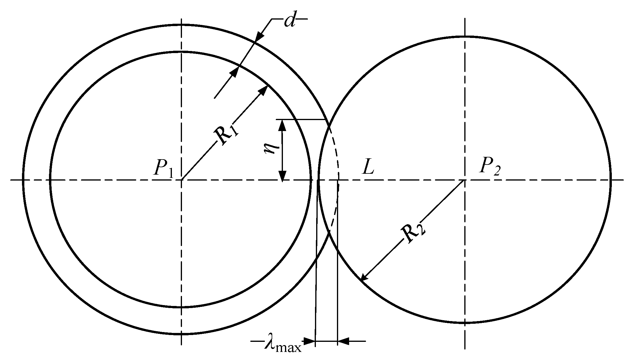
The structure of the flexographic printing pressure generation mechanism is shown in
Figure 1. The flexible printing plate is wrapped and fixed on the surface of the plate cylinder, and the impression cylinder is in direct contact with the flexible plate. Since the elastic modulus of the cylinders is much higher than that of the flexible plate, only the deformation of the flexible plate is considered during contact. Let the radius of the plate cylinder be
R1, the thickness of the flexible plate be
d, the radius of the impression cylinder be
R2, and the distance between
P1 and
P2 be
L. When
L >
R1 +
d +
R2, the flexible plate is uncompressed and undeformed, resulting in no printing pressure. Conversely, when
L <
R1 +
d +
R2, the flexible plate in the contact zone is compressed to generate printing pressure, where
λ is the compression amount and
η is the half-width of the contact zone.
According to Hertzian contact theory, the contact between two cylinders forms a rectangular contact area, and the geometric dimensions of the contact region are much smaller than the radius of the rollers, the half-width
η of the contact zone and the maximum compression
λmax at the centerline satisfy the following equation:
2.2. Pressure Calculation Model Based on Hertz’s Elastic Contact Theory
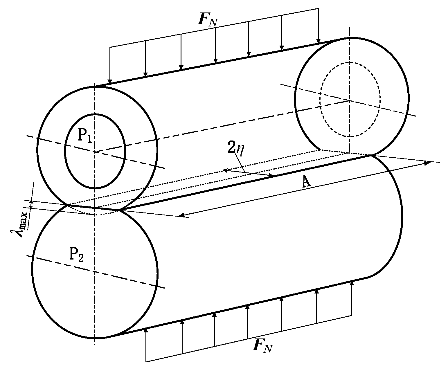
The interaction between the rigid impression cylinder and the flexible plate cylinder is regarded as line contact between two cylinders based on Hertz’s elastic contact theory, forming an approximately rectangular contact zone [
15]. The normal force distribution in the contact zone is shown in
Figure 2.
Under compression, the line contact transitions to area contact, which can be approximated as a rectangular area with side lengths
A (axial length of the cylinder) and 2
η (width of the contact zone). For line contact, the relationship between the maximum contact stress
σmax and the normal force
FN is as follows [
16]:
where
E3 is the equivalent elastic modulus, and
R3 is the equivalent radius of curvature of the contact zone, calculated as follows:
In Equation (3), E1 and μ1 are the elastic modulus and Poisson’s ratio of the flexible plate, respectively; E2 and μ2 are the elastic modulus and Poisson’s ratio of the impression cylinder, respectively.
The maximum stress
σmax can also be expressed as follows:
The printing pressure
P is defined as the average pressure in the contact zone, and its relationship with the normal force
FN is as follows:
Substituting Equations (1), (2) and (5) into Equation (6), the mathematical model of printing pressure
P is derived as follows:
The theoretical analysis presented above lays a solid foundation for the design of the flexographic printing pressure control system. Based on this foundation, the next chapter will construct the specific control system architecture.
This model establishes the quantitative relationship between printing pressure P and structural parameters (e.g., R1, R2, d) and deformation parameters (e.g., λmax), laying a theoretical foundation for the design of the pressure control system.
3. Flexographic Printing Pressure Control System
Based on the contact zone pressure model, this chapter will elaborate on the composition, working principles, and control logic of the flexographic printing pressure control system.
3.1. Structural Composition
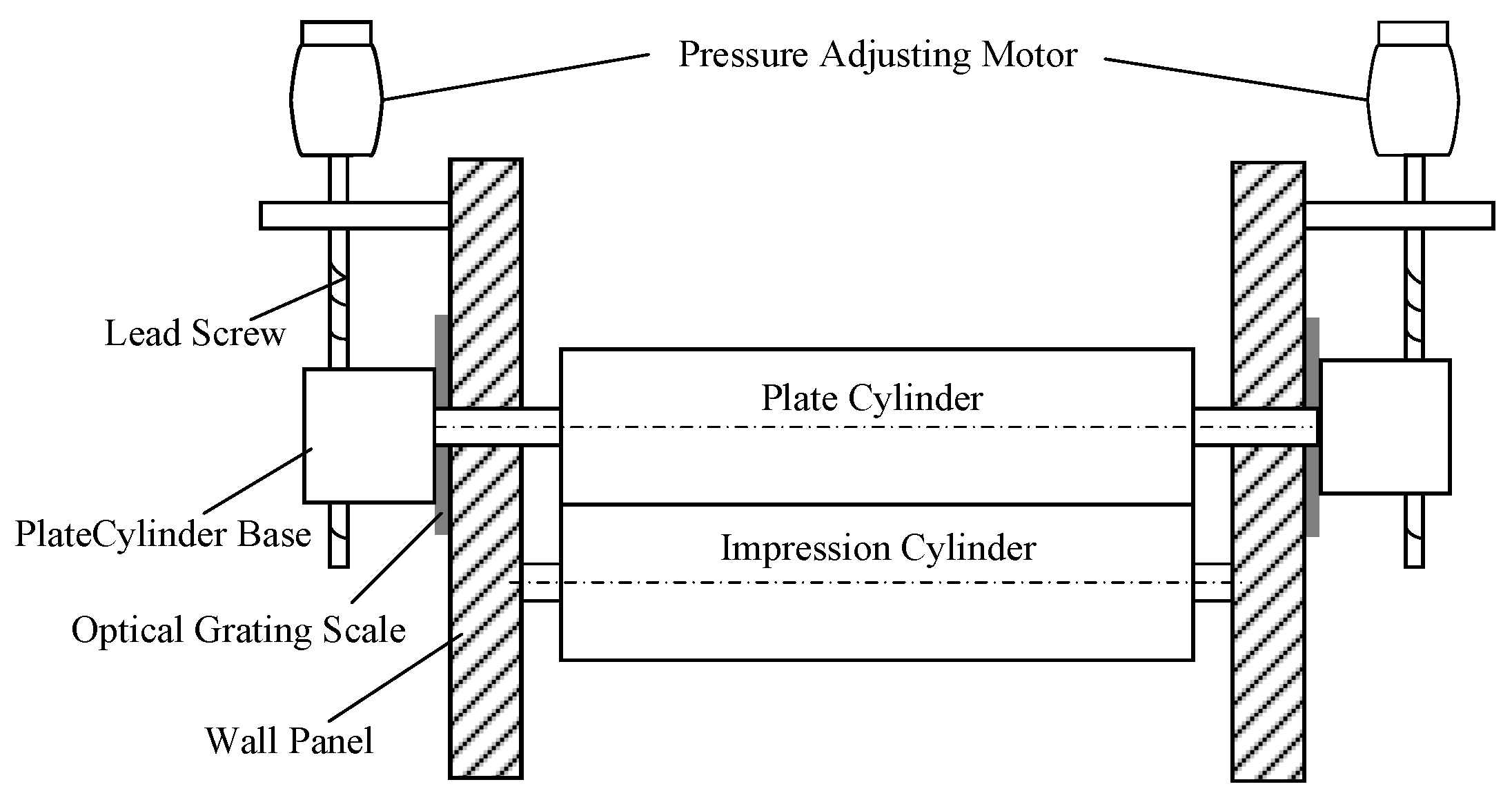
The pressure adjustment mechanism of the flexographic printing press is an integrated electromechanical system consisting of four core components, as shown in
Figure 3.
Actuator Units: Including the plate cylinder, impression cylinder, and cylinder base, which are the core components for generating and transmitting printing pressure.
Transmission System: Composed of a lead screw and sliding guide rails, realizing precise conversion from rotational motion to linear motion and ensuring accurate force transmission.
Structural Framework: Wall panels provide stable support for the entire system, ensuring the positional accuracy of each component during operation. An optical grating scale is employed to measure the actual displacement of the plate cylinder base in real-time, eliminating errors induced by lead screw transmission backlash and ensuring displacement detection precision reaches the sub-micron level.
Power Source: PMSMs provide driving force for precise motion control, enabling micrometer-level adjustment of the cylinder base.
3.2. Working Principle of Pressure Adjustment
The pressure adjustment process follows a five-stage workflow: power initiation → motion conversion → vertical transmission → geometric parameter adjustment → pressure control implementation, as detailed below:
- (1)
Power Initiation: The control system activates the PMSM, which generates precise rotational torque to drive the lead screw, converting electrical energy into mechanical energy.
- (2)
Motion Conversion: The lead screw converts rotational motion into linear displacement of the cylinder base through threaded engagement, realizing accurate conversion of motion forms.
- (3)
Vertical Transmission: The cylinder base moves vertically along the sliding guide rails (with constrained lateral freedom), ensuring the precision and stability of the motion direction.
- (4)
Geometric Parameter Adjustment: The displacement of the cylinder base changes the center distance L between the plate cylinder and the impression cylinder, adjusting the compression degree of the flexible plate.
- (5)
Pressure Control Implementation: Variations in the compression degree of the flexible plate directly alter the printing pressure, achieving precise control of the target pressure.
The dual-motor configuration ensures bilateral pressure balance, and the high-precision lead screw and guide rail mechanism guarantee the accuracy of displacement adjustment. This integrated design maintains consistent printing quality across different substrates under continuous production conditions.
3.3. Printing Pressure Control Principle
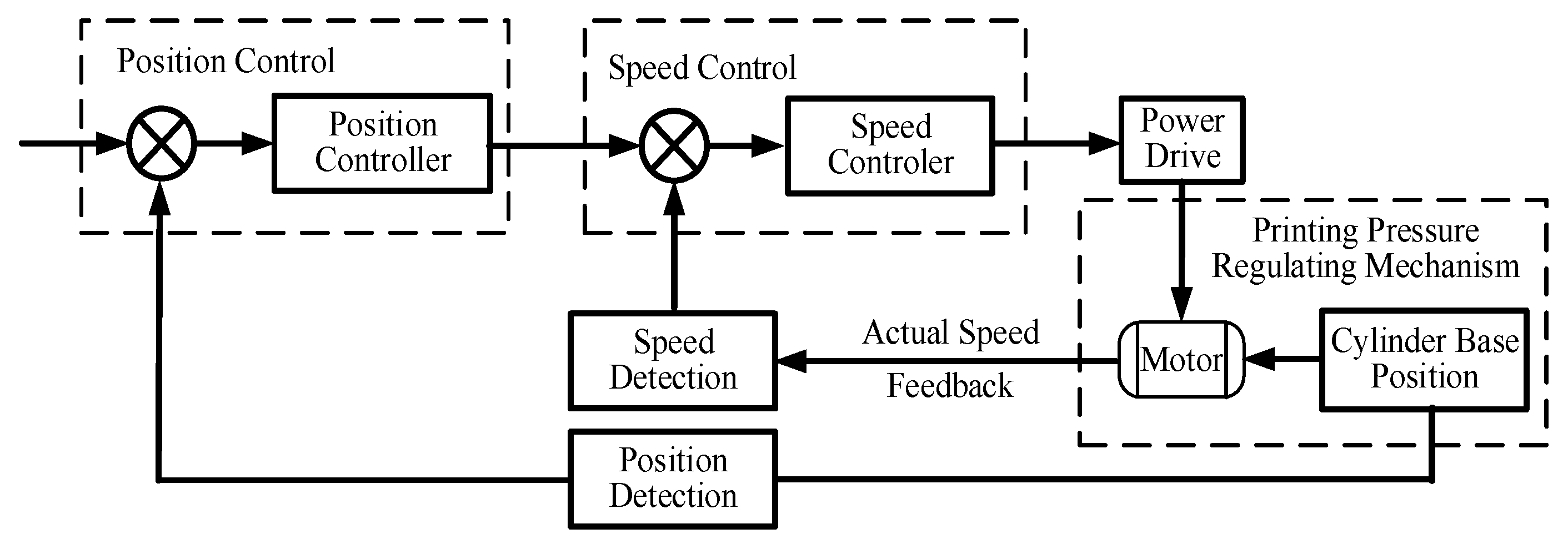
The pressure control system adopts a closed-loop control architecture, as shown in
Figure 4. After inputting the target displacement command (converted from the target pressure based on Equation (7)), the system regulates the motor’s current loop, speed loop, and position loop. The motor drives the lead screw to displace the cylinder base, and the actual displacement (measured by a displacement sensor) is fed back to the command terminal to form closed-loop control.
Synchronous performance is a key requirement for motion control: dual motors must follow unified motion protocols (forward/reverse) to ensure consistent displacement of the cylinder base when receiving the same command, guaranteeing the uniformity of printing pressure across the entire width of the substrate.
4. Design of Fuzzy PI Controller and Cross-Coupled Synchronous Strategy
To address the nonlinearity of PMSMs and the complexity of printing working conditions, this chapter designs a fuzzy PI controller for the motor speed loop and integrates it with a cross-coupled synchronous strategy to achieve high-precision dual-motor synchronization control.
4.1. Fuzzy PI Control Strategy for PMSMs
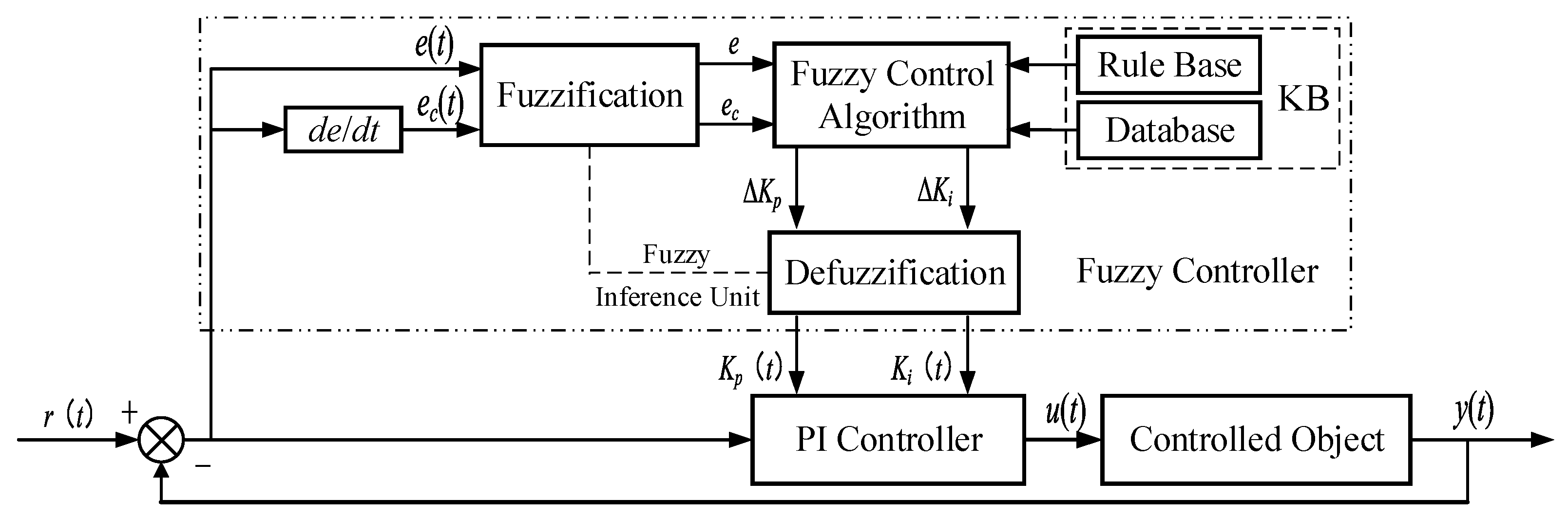
Traditional PI control struggles to adapt to the nonlinear characteristics of PMSMs and variable working conditions. Thus, a parameter self-tuning fuzzy PI controller is adopted in the speed loop, whose working principle is shown in
Figure 5. The controller takes the speed error
e (difference between the reference speed and actual speed) and the error change rate
ec as inputs, and outputs the correction amounts Δ
Kp and Δ
Ki of the PI parameters to dynamically adjust
Kp and
Ki in real time.
The dynamic adjustment of PI parameters is calculated as follows:
where
Kp0 and
Ki0 are the initial proportional and integral gains, determined by system identification and the Ziegler-Nichols tuning method; Δ
Kp(
t) and Δ
Ki(
t) are the real-time correction amounts generated by the fuzzy rule base.
After determining the control strategy, it is necessary to establish a corresponding fuzzy rule base to achieve parameter self-tuning functionality.
4.2. Fuzzy Rule Design
The universe of discourse for inputs (e, ec) and outputs (ΔKp, ΔKi) is set to [−6, 6], and triangular membership functions are adopted for all variables. Seven linguistic variables are defined: Negative Large (NL), Negative Medium (NM), Negative Small (NS), Zero (ZO), Positive Small (PS), Positive Medium (PM), Positive Large (PL).
The fuzzy rule base transforms qualitative expert knowledge into quantitative mathematical computations. The fundamental principles of rule design are as follows: First, a robust control strategy is implemented within large error ranges to ensure rapid system response. Second, a damping logic is introduced during the error reduction process to suppress dynamic overshoot. Subsequently, the predictive function of the error change rate is utilized to mitigate cyclic oscillations near the equilibrium point. Finally, control outputs are fine-tuned during the steady-state phase to eliminate steady-state error. Together, these principles constitute a fuzzy inference mechanism characterized by superior robustness and steady-state performance.
Based on expert experience and control requirements, fuzzy rules for Δ
Kp and Δ
Ki are established as shown in
Table 1 and
Table 2, respectively. These rules form the core of the fuzzy inference system, realizing the mapping from input (
e,
ec) to output (Δ
Kp, Δ
Ki).
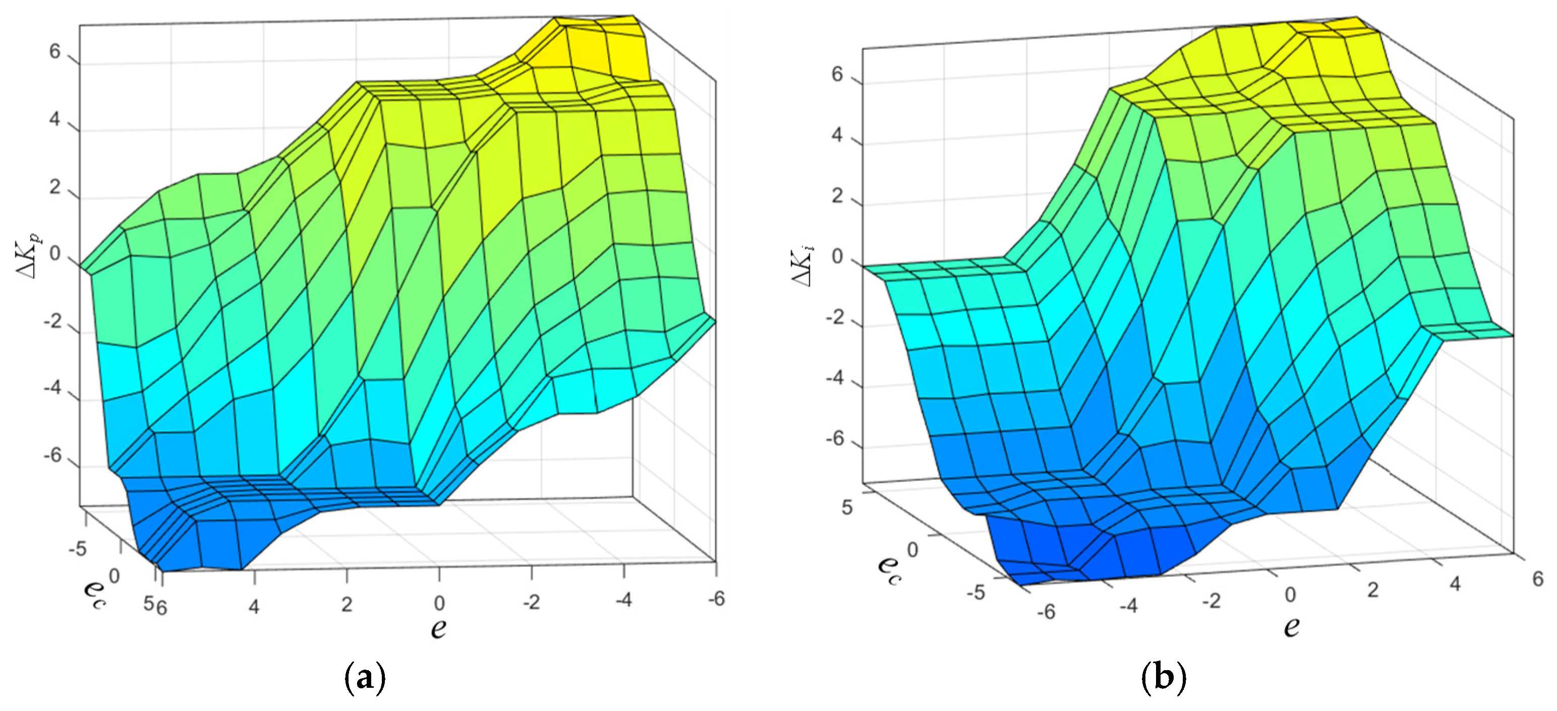
The input–output mapping relationships of the fuzzy controller are shown in
Figure 6. It can be seen that the control surfaces are continuous and smooth, covering the entire input space [−6, 6] × [−6, 6], ensuring that all input combinations have clear corresponding output parameters. When the error
e is large, the controller increases
Kp to enhance the response speed; when the error change rate
ec is large, the controller adjusts
Ki to avoid overshoot, ensuring the stability and rapidity of the control system.
4.3. Analysis of Fast Response Mechanism Without Feedforward
Addressing the convention that high-precision motion control typically employs feedforward control to reduce phase lag, this study intentionally adopts a pure feedback architecture. The intrinsic mechanism relies on the nonlinear gain scheduling characteristics of fuzzy logic. While feedforward control effectively improves transient response, its performance is highly dependent on the accuracy of the inverse model of the plant. In flexographic printing, the Hertzian nonlinear stiffness of the contact zone and the time-varying nature of consumable properties make constructing a precise global feedforward model extremely challenging. The proposed Fuzzy PI controller implements dynamic reconfiguration of controller gains by monitoring the error
e and its rate of change
ec in real-time. As illustrated in
Figure 6a, during the transient start-up or initial disturbance phases (where
e is large), the fuzzy rules adjust the proportional gain
Kp to its peak value. This ‘high-gain injection’ mechanism physically generates a strong torque output similar to a feedforward signal. Consequently, it effectively overcomes the phase lag inherent in traditional linear PI control and ensures rapid response without relying on a precise system model.
4.4. Cross-Coupled Synchronous Control Strategy for Dual Motors
Dual-motor synchronous control includes mechanical synchronization and electrical synchronization. Mechanical synchronization is prone to friction interference and low precision, while electrical synchronization (software-controlled) has higher precision and lower cost. Electrical synchronization mainly includes master-command control, master-slave control, and cross-coupled control. Among them, cross-coupled control realizes real-time bidirectional compensation between motors, making it suitable for high-precision synchronization scenarios.
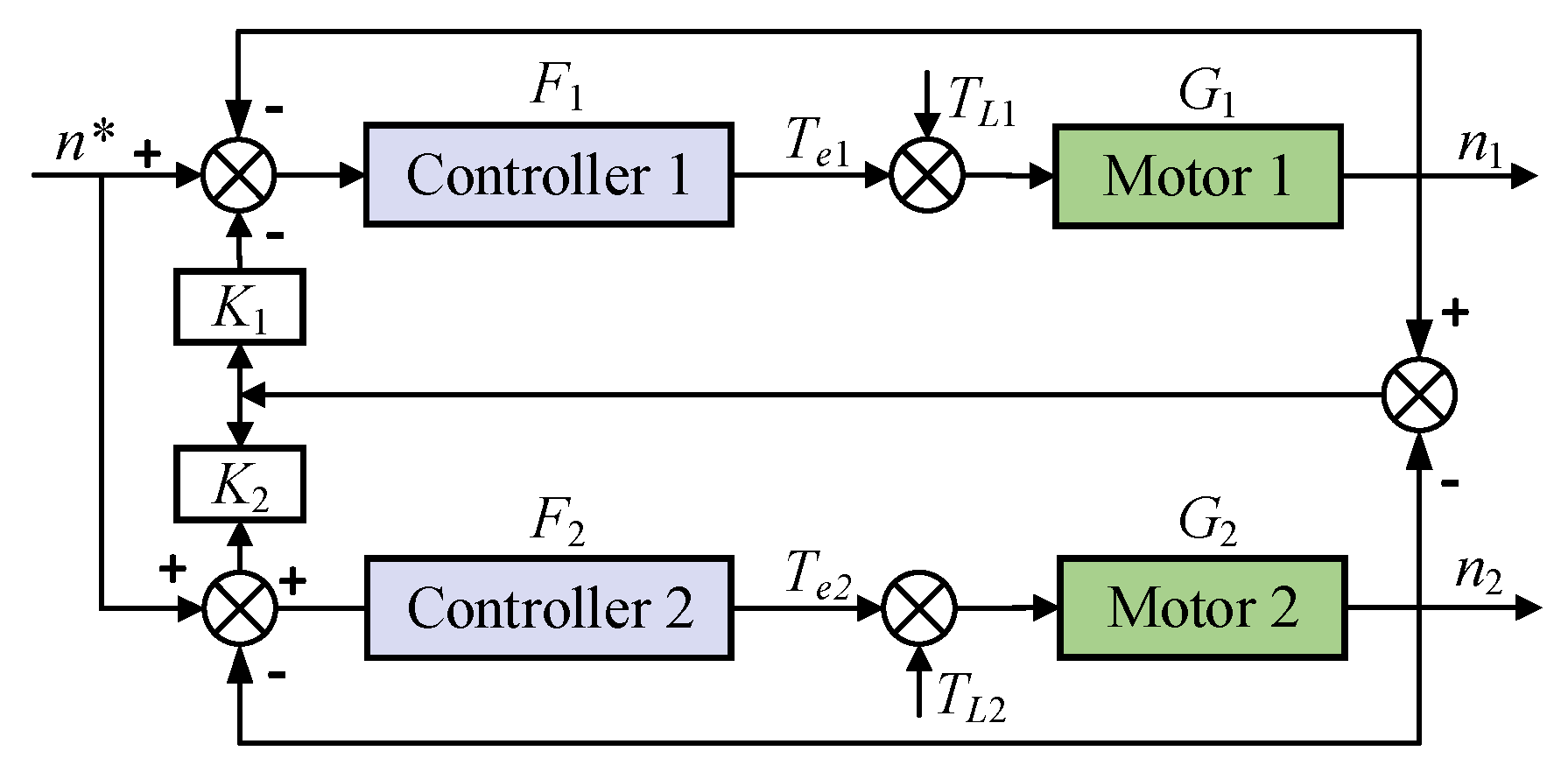
The structure of the cross-coupled synchronous control system is shown in
Figure 7. The system monitors the speed of each motor in real time to achieve dynamic feedback. When one motor has speed deviation, the system triggers the other motor to compensate through the cross-coupling link, maintaining synchronization accuracy. Controller 1 and Controller 2 respectively implement closed-loop control for Motor 1 (drive-side pressure adjustment) and Motor 2 (operating-side pressure adjustment), forming a dual-channel independent regulation architecture with mutual coupling compensation.
The key parameters of the system are defined as follows:
n* is the reference input speed, in units of rpm;
F1,
F2 are the transfer functions of Controller 1 and Controller 2;
Te1,
Te2 are the output torques of the two motors;
TL1,
TL2 are the external disturbances of the two motors;
G1,
G2 are the transfer functions of the motor dynamics;
ω denotes the angular velocity of the motor (unit: rad/s), which is related to the rotational speed
n (unit: r/min) by the equation
ω =
kn. Here,
k represents the unit conversion coefficient, derived from
k = 2
π/60 ≈ 0.1047.
K (denoted as
K1 and
K2 in
Figure 7, assuming
K =
K1 =
K2) is the cross-coupling coefficient, characterizing the intensity of speed synchronization compensation between the dual motors. It should be noted that the conversion coefficient
k is employed for dimensional unification, whereas the coupling coefficient
K serves to regulate the gain of synchronous control; thus, they possess distinct physical meanings.
Since the two motors have the same parameters and synchronized startup speed, the displacement of the cylinder base is synchronized in real time. Based on automatic control theory, the speed equations of Motor 1 and Motor 2 are derived as follows:
Each speed equation includes three terms: the reference tracking term (reflecting the system’s ability to track the reference speed n*), the disturbance suppression term (offsetting the impact of external disturbances TL1, TL2, and the coupling interaction term (realizing speed compensation between the two motors). These three terms work together to ensure the synchronization accuracy and anti-disturbance performance of the system.
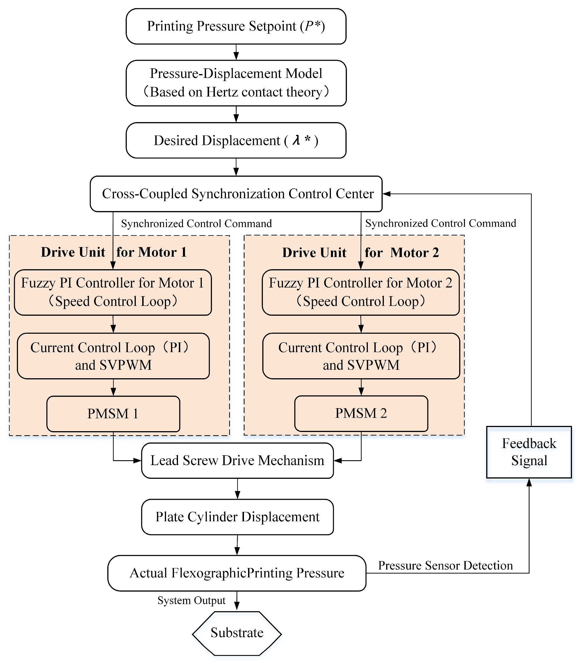
4.5. Integrated Intelligent Synchronous Control System for Flexographic Printing Pressure
Integrating the fuzzy PI controller and cross-coupled synchronous strategy, the dual-motor flexographic printing pressure intelligent synchronous control system is constructed, as shown in
Figure 8. The system adopts a three-layer hierarchical architecture: target conversion layer, synchronization coordination layer, and drive execution layer, realizing full-process closed-loop control of “pressure command → displacement conversion → synchronous coordination → dual-channel drive → real-time feedback”.
(1) Target Conversion Layer: The target printing pressure P* is input, and the target displacement λ* of the cylinder base is calculated through the pressure-displacement conversion model (derived from Equation (7)), realizing the mapping from process parameters to motion parameters.
(2) Synchronization Coordination Layer: Taking the cross-coupled synchronous control center as the core, it distributes the target displacement λ* to the two drive channels in parallel, collects the actual displacement feedback of the two motors, calculates the synchronization error, and generates compensation commands to ensure the synchronization of the two motors.
(3) Drive Execution Layer: Each drive unit adopts a four-stage conversion process: ① Speed loop: The fuzzy PI controller adjusts the speed in real time and outputs the current reference value; ② Current loop: The PI controller combined with Space Vector Pulse Width Modulation (SVPWM) generates precise driving voltage; ③ Actuation: The PMSM converts electrical energy into rotational motion; ④ Mechanical conversion: The lead screw converts rotational motion into linear displacement of the cylinder base.
The dual motors drive the cylinder base to move synchronously, generating the actual printing pressure. High-precision displacement/pressure sensors monitor the system state in real time and feed back to the synchronization coordination layer, forming a closed-loop control system that ensures precise and stable printing pressure control.
5. Simulation Analysis
To verify the effectiveness of the proposed control strategy, a simulation platform was built using MATLAB R2021b/Simulink. The simulation parameters are set as follows: R1 = 50 mm, R2 = 40 mm, d = 5 mm, E1 = 2.5 GPa, E2 = 200 GPa, motor rated power = 1.5 kW, rated speed = 3000 rpm, load torque = 5 N·m. Two sets of simulations were conducted: single-motor control system and dual-motor cross-coupled synchronous control system.
5.1. Simulation of Single-Motor Control System
The single-motor control system is modeled as a traditional mechanical shaft synchronization structure. In this configuration, a single motor drives the lead screw mechanisms on both sides simultaneously via a rigid transmission shaft to maintain theoretical parallelism of the cylinder base.
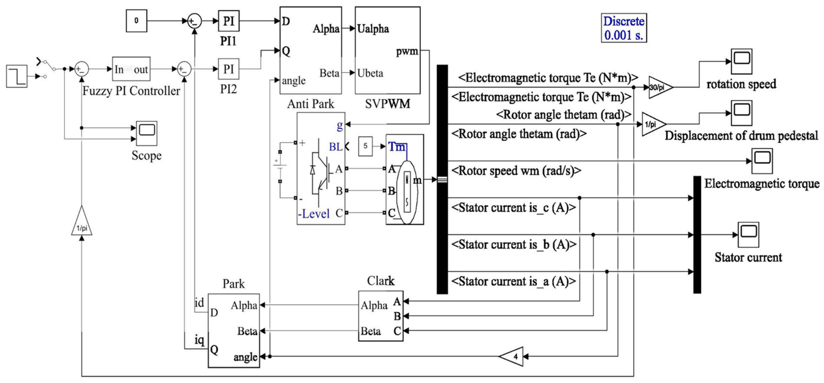
A three-loop vector control model (current loop, speed loop with fuzzy PI control, position loop) was established for the single-motor system, as shown in
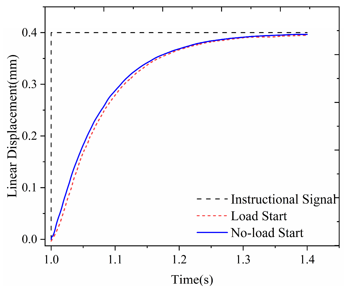
Figure 9. The target displacement of the cylinder base was set to 0.4 mm, and the position response curves under no-load and load conditions were obtained, as shown in
Figure 10.
The specific definitions of the simulation conditions are as follows: ‘No-load’ refers to the free-travel phase where the impression cylinder has not yet contacted the plate cylinder, and the system is subject only to guide rail friction. ‘Load’ refers to the printing phase where the impression cylinder is pressed against the plate cylinder, generating a Hertzian contact reaction force.
Simulation results indicate that during the no-load conditions, the single-motor system achieves a settling time of approximately 0.35 s. In this phase, the steady-state displacement error is maintained within ±0.3%. Upon entering the load conditions, the reaction force disturbance extends the settling time to approximately 0.40 s. More critically, displacement oscillations under load intensify, causing the equivalent pressure fluctuation to expand to ±0.8%. This indicates that the single-motor system has poor anti-disturbance performance under load, leading to uneven pressure distribution and reduced control precision.
5.2. Simulation of Dual-Motor Cross-Coupled Synchronous Control System
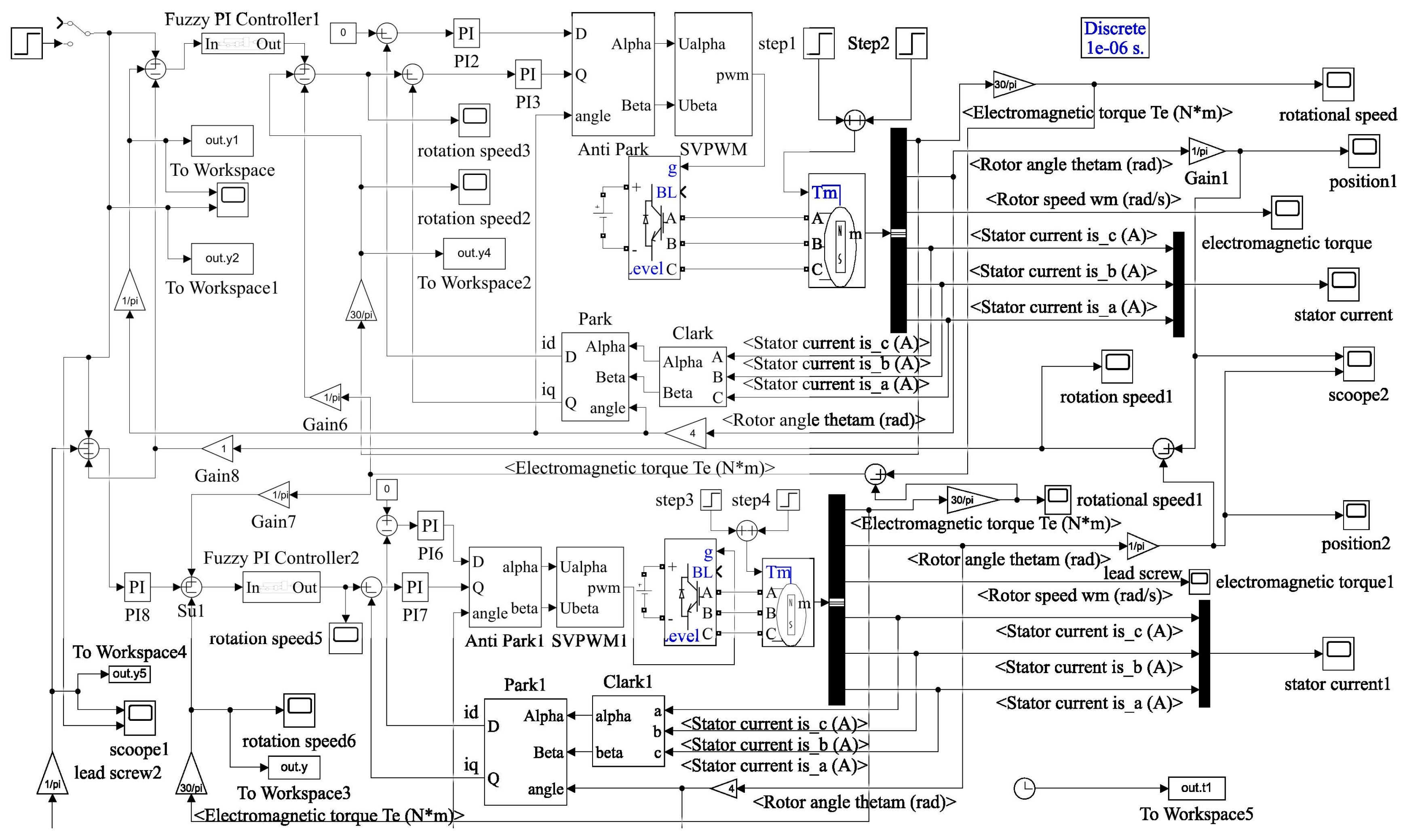
The dual-motor synchronous control simulation model was established based on the proposed strategy, as shown in
Figure 11. The target displacement of the cylinder base was set to 0.4 mm, and three typical working conditions were tested: load startup, single-motor disturbance, and multiple disturbances.
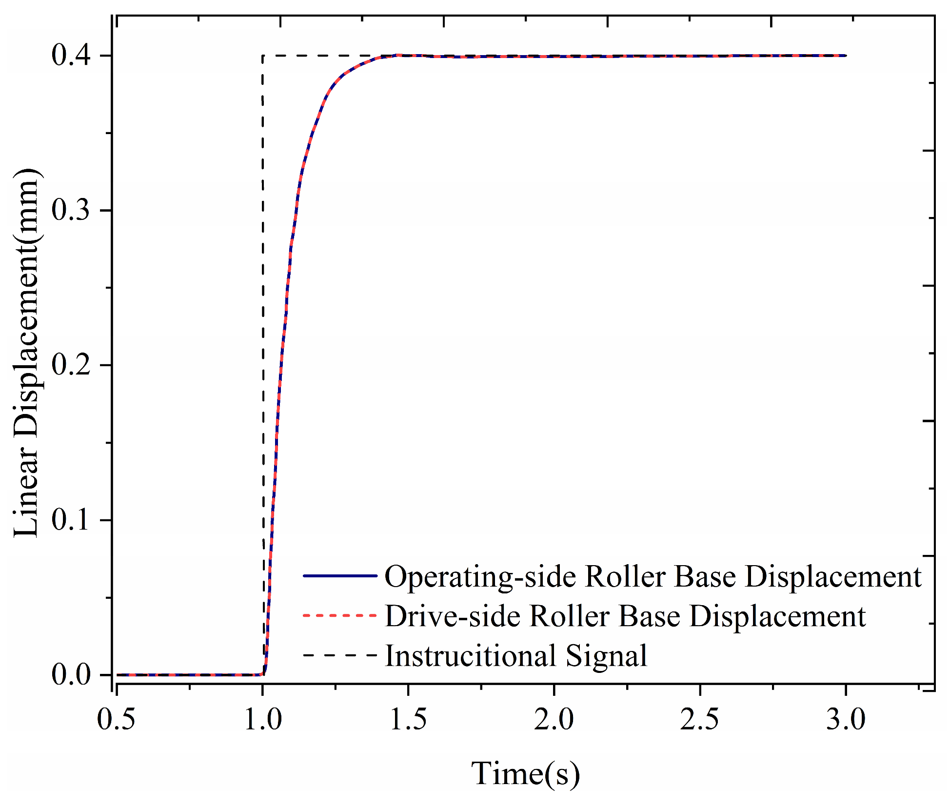
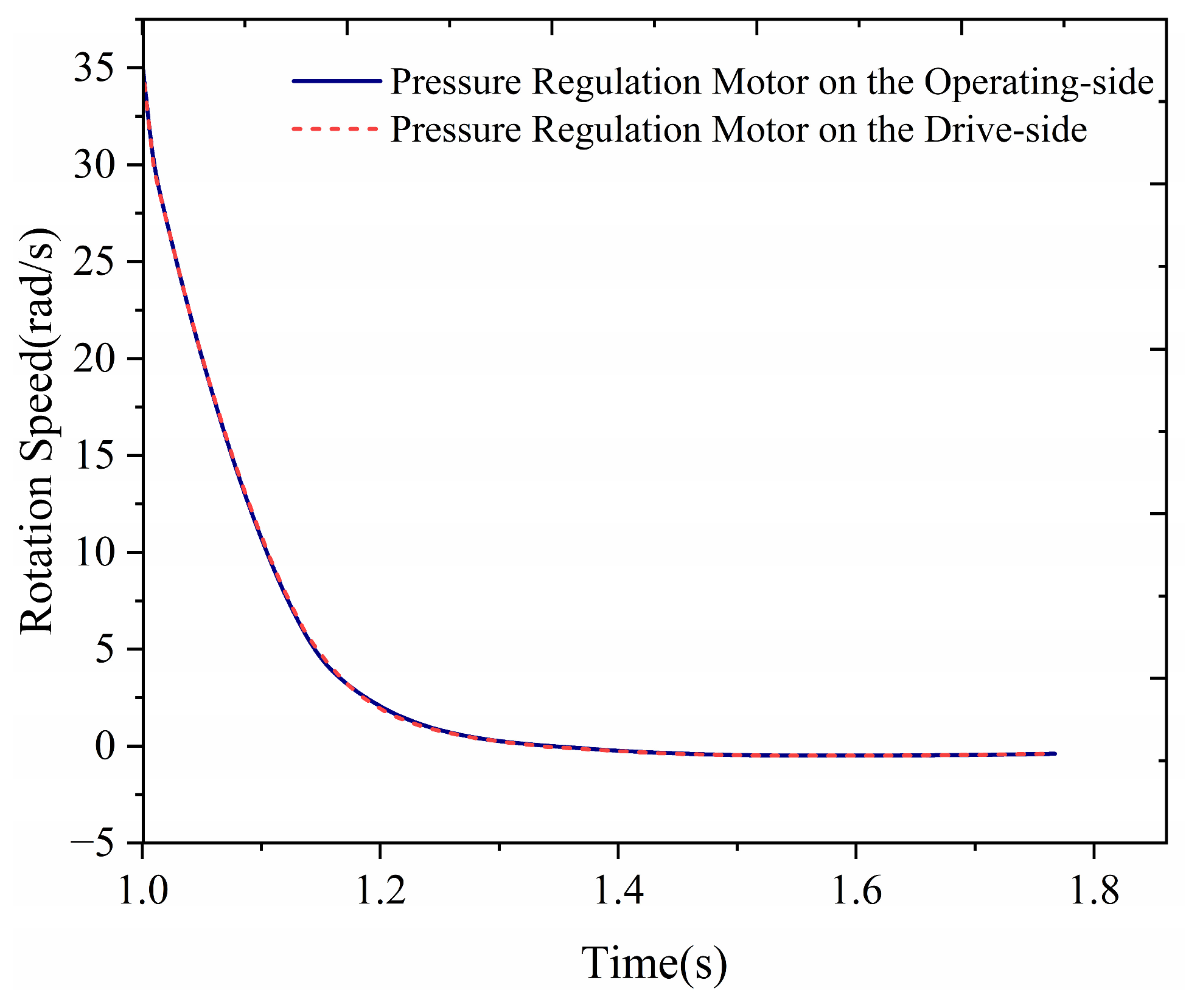
Load Startup: Both motors started under load at t = 1 s. The position response curve is shown in
Figure 12, and the speed curve is shown in
Figure 13. The displacement of the two motors and the cylinder base maintains high consistency, with an initial synchronization error of less than ±0.02 mm. The system response time is 0.15 s, stabilizes within 0.8 s, and the overshoot is controlled below 5%. The pressure fluctuation range is ±0.3%, and the continuous operation stability reaches 99.5%.
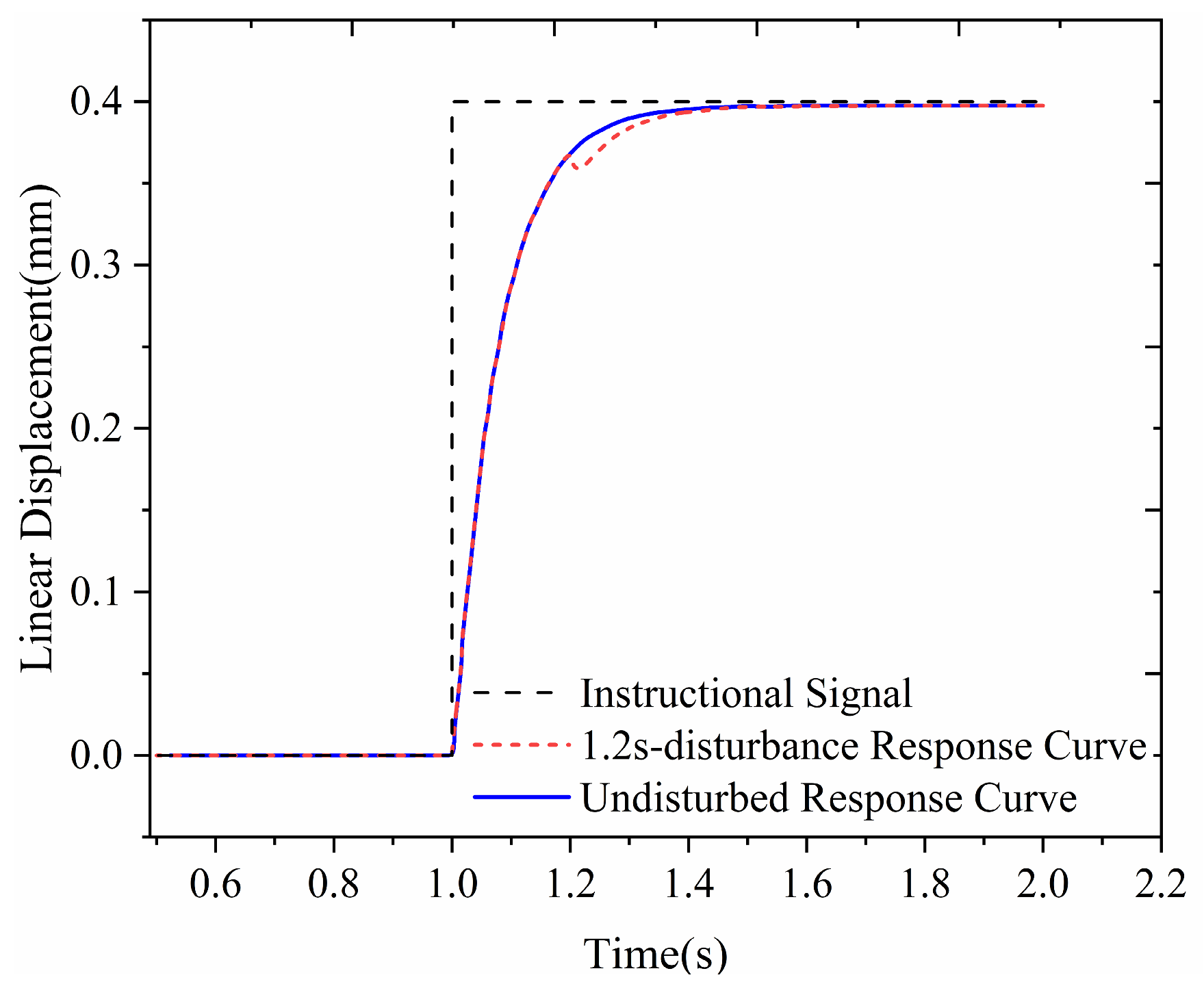
Single-Motor Disturbance: A displacement step disturbance (amplitude = 0.05 mm) was applied to the operating-side motor at t = 1.2 s. The position response curve is shown in
Figure 14. The system suppresses the disturbance within 0.3 s, and the displacement returns to the target value (0.4 mm). It is noted that this recovery time (0.30 s) is slightly longer than the start-up positioning time (0.15 s). This is a deliberate trade-off of the cross-coupled strategy, which prioritizes dual-motor synchronization over single-axis response speed. By actively constraining the undisturbed motor to match the trajectory of the disturbed one, the system ensures the relative synchronization error remains within ±0.002 mm, demonstrating excellent anti-disturbance performance.
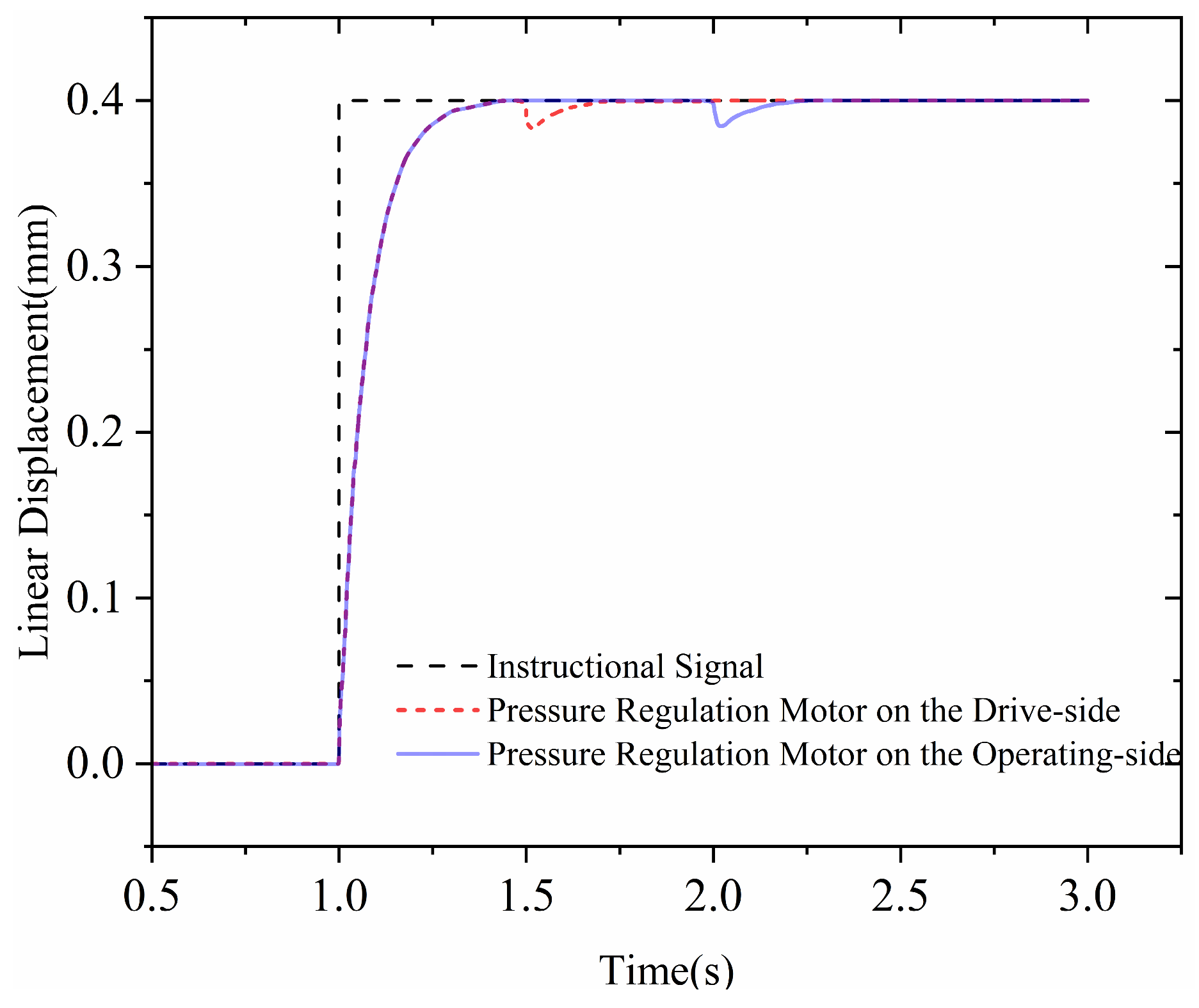
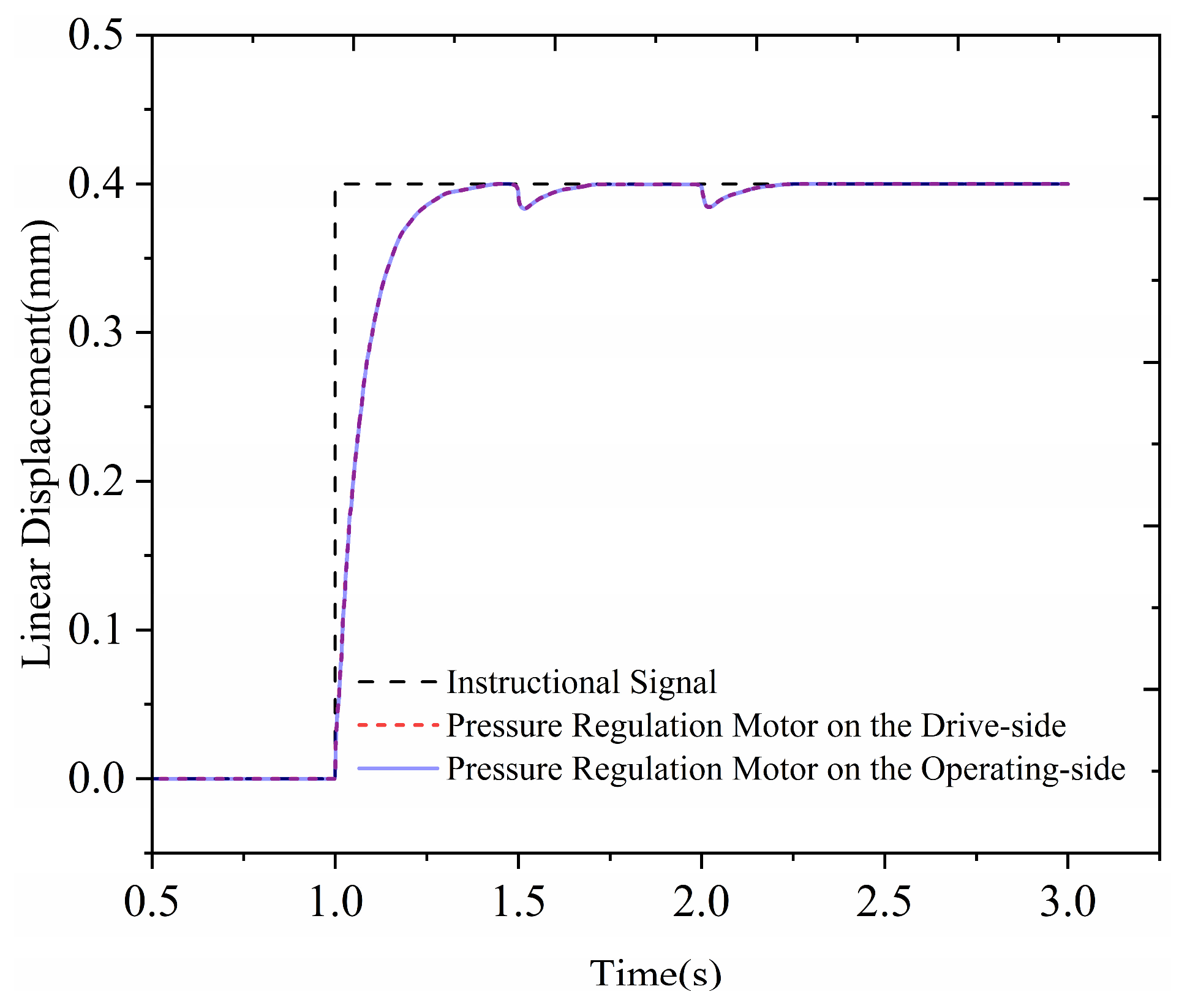
Multiple disturbances: To rigorously evaluate the synchronization performance, independent displacement step disturbances (amplitude = 0.05 mm) are applied to the drive-side motor and the operating-side motor in rapid succession (at t = 1.5 s and t = 2.0 s, respectively). It is crucial to note that the system behavior under this scenario differs fundamentally depending on the control strategy: Under the independent control strategy, the states of the two motors are mutually isolated. Consequently, when a disturbance is applied to one motor (e.g., at t = 1.5 s), it does not influence the state of the other motor. The two motors operate independently without mutual coordination. Under the cross-coupled control strategy, the disturbances trigger a coordinated response. At t = 1.5 s and t = 2.0 s, when one motor is disturbed, the other motor—physically undisturbed—actively adjusts its speed to “follow” the disturbed one via the cross-coupling algorithm. This mechanism ensures that the relative position error is minimized to maintain the parallelism of the two cylinders.
To verify the specific contribution of the cross-coupling mechanism, a comparative simulation was conducted under multiple disturbance conditions.
Figure 15 and
Figure 16 present the contrast between the independent control strategy (without cross-coupling, K = 0) and cross-coupled synchronous control strategy (K > 0).
Figure 15 presents the system response under the independent control strategy (K = 0). As anticipated, the two motors exhibit complete isolation. When the drive-side motor is subjected to a load disturbance at t = 1.5 s, its speed drops, causing a deviation from the target displacement. However, the operating-side motor, lacking information exchange, continues its trajectory unaffected. This “indifference” results in a significant synchronization gap, which physically corresponds to a momentary tilting of the plate cylinder. A similar phenomenon occurs at t = 2.0 s: when the operating-side motor is disturbed, the drive-side motor fails to react, creating a reverse synchronization error. These results indicate that without a coupling mechanism, the system cannot maintain cylinder parallelism under asymmetric loading.
In contrast,
Figure 16 illustrates the performance of the proposed cross-coupled synchronous control strategy under identical conditions. The introduction of the cross-coupling term (Equations (9) and (10)) fundamentally alters the system behavior. At t = 1.5 s, when the drive-side motor is disturbed, the control algorithm detects the incipient speed difference and actively generates a deceleration command for the undisturbed operating-side motor. Consequently, the operating-side motor “follows” the dynamic change of the drive-side motor. As shown in
Figure 16, the displacement curves of both motors remain tightly overlapped throughout both disturbance events (t = 1.5 s and t = 2.0 s). Although the absolute speed of the system fluctuates transiently to reject the load, the relative synchronization error is effectively suppressed.
Comparing
Figure 15 and
Figure 16, it is evident that while the independent control strategy can reject disturbances individually, it fails to maintain coordination. The proposed cross-coupled strategy successfully eliminates the synchronization gaps observed in the independent method, validating its critical role in ensuring the uniformity of flexographic printing pressure.
5.3. System Robustness Verification Under Time-Varying Periodic Disturbances
Although the step disturbance simulations in
Section 5.2 verified the basic synchronization performance, the actual flexographic printing environment involves complex dynamic loads. Factors such as roller eccentricity, gear meshing backlash, and mechanical vibrations introduce time-varying periodic disturbances and random noise, which challenge the system’s robustness. To rigorously validate the proposed strategy under realistic conditions, a composite time-varying disturbance model
TL (t) was constructed:
where
Tstep is the nominal Hertzian contact load (simulating the sudden engagement of printing pressure);
Aeccsin(2
πft) represents the periodic disturbance component induced by roller eccentricity and gear transmission (with amplitude
Aecc and frequency
f correlated to the motor speed); and
δ(
t) denotes bounded random noise simulating environmental vibrations.
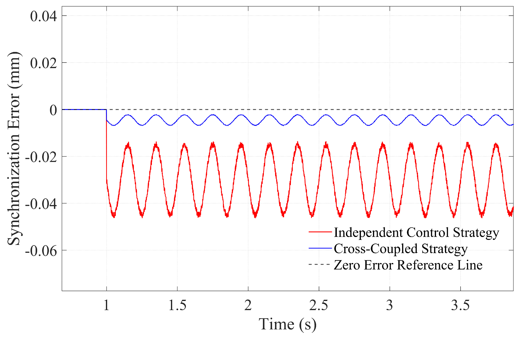
The comparative synchronization error curves under composite time-varying disturbances are illustrated in
Figure 17. The red solid line, representing the Independent Control Strategy, exhibits a continuous, large-amplitude sinusoidal oscillation (approximately 0.04 mm peak-to-peak) superimposed with high-frequency noise. This indicates that in the absence of a cross-coupling mechanism, mechanical eccentricity and environmental vibrations are directly transmitted to the cylinder position, resulting in significant periodic synchronization errors. In stark contrast, the blue solid line depicting the proposed Cross-Coupled Strategy remains flat and tightly adheres to the Zero Error Reference Line. This comparison quantitatively demonstrates that the proposed algorithm effectively attenuates periodic fluctuations induced by roller eccentricity, maintaining the synchronization error within a negligible range (±0.002 mm), thereby verifying the system’s superior robustness against complex, realistic printing disturbances.
To provide a comprehensive evaluation,
Table 3 quantitatively compares the performance of the three control strategies simulated in this study.
Compared to the traditional single-motor baseline, the proposed intelligent cross-coupled strategy significantly improves transient response, reducing the load settling time from 0.40 s to under 0.30 s. Furthermore, it enhances pressure stability by confining fluctuations to ±0.3%, representing a 62.5% improvement over the ±0.8% observed in the baseline system. In terms of synchronization under periodic disturbances, the proposed strategy suppresses the error to ±0.002 mm, whereas the independent control strategy exhibits a much larger error of approximately 0.04 mm. Overall, the proposed system achieves a 99.5% operational stability, confirming its superiority for high-precision flexographic printing.
6. Conclusions
This study addresses the problems of uneven pressure and slow response in flexographic printing pressure control under load variations. A dual-motor cross-coupled synchronous control system integrating Hertzian elastic contact theory and fuzzy PI control is proposed. The main conclusions are as follows:
- (1)
A printing contact zone pressure calculation model based on Hertz’s elastic contact theory is established, which clarifies the quantitative relationship between printing pressure and structural/deformation parameters, providing a theoretical basis for precise pressure control.
- (2)
Simulation results indicate significant performance degradation in the single-motor three-loop vector control system under load conditions. Specifically, the load settling time extends to 0.40 s (indicating distinct response lag), and limited by mechanical transmission flexibility, the steady-state pressure fluctuation expands to 0.8%. These quantitative metrics confirm that the traditional system fails to meet the stringent requirements for pressure uniformity and stability in high-precision printing.
- (3)
The proposed dual-motor cross-coupled synchronous control system achieves high-precision speed synchronization between the two motors. Under complex working conditions—including load start-up, sudden step disturbances, and time-varying periodic disturbances induced by roller eccentricity—the system demonstrates superior dynamic performance and robustness. Simulation results confirm that it not only completes transient disturbance compensation within 0.30 s with pressure fluctuations confined to ±0.3%, but also effectively attenuates continuous periodic oscillations, suppressing the synchronization error to within ±0.002 mm (compared to 0.04 mm in independent control). Overall, the system maintains 99.5% operational stability, effectively improving the uniformity and stability of printing pressure control.
The research results provide theoretical support and technical solutions for the design of high-precision flexographic printing pressure systems, with important practical value for improving print quality and promoting the intelligent upgrading of the printing industry.
Future work will focus on the following aspects: (1) Develop adaptive algorithms for dynamic optimization of the coupling coefficient K to enhance the system’s adaptability to variable loads; (2) integrate machine learning techniques for intelligent parameter tuning of the fuzzy PI controller, further improving control precision; and (3) conduct experimental verification based on a physical prototype to validate the practical application effect of the control system.




 ,
,