1. Introduction
Suspension is a key chassis subsystem that strongly influences ride comfort and handling stability. At present, most vehicles rely on springs and dampers to provide the stiffness and damping required for vibration isolation; therefore, improving how stiffness and damping are shaped remains a central topic in suspension engineering [
1,
2,
3]. Passive suspensions use fixed (or piecewise) springs together with dampers of constant damping coefficients. Because of their simple, reliable structure and low cost, passive suspensions remain the dominant configuration in production vehicles. However, a single parameter set cannot adapt well to varying operating conditions and increasingly stringent performance requirements. In contrast, active suspensions regulate stiffness and damping through powered actuators and can, in principle, achieve superior vibration attenuation. Hydraulic, pneumatic, and electromagnetic actuation technologies have all been explored [
4,
5]. Nevertheless, generating forces that counteract vertical motions requires substantial energy consumption, which is inconsistent with current trends toward electrification and energy efficiency. In addition, actuator bandwidth is limited by available power, system architecture, and intrinsic actuation dynamics, which constrain achievable closed-loop performance. Semi-active suspensions can provide effective vibration control with much lower energy use by adjusting damper characteristics or the working medium. However, mechanically adjustable or magnetorheological semi-active actuators cannot directly generate the full-quadrant force capability of fully active actuators [
6,
7,
8,
9].
From the force-generation viewpoint, a fully active actuator can deliver control forces across all four quadrants of the force–velocity plane. It can generate forces in the same direction as the motion and actively inject energy to compensate for road-induced vertical disturbances, thereby reducing the net vibration energy transmitted to the vehicle. In contrast, semi-active actuators exhibit output characteristics similar to passive dampers: they mainly operate in the first and third quadrants, generating forces opposite to the motion to reject incoming disturbances while dissipating energy. Thus, semi-active actuation does not fundamentally change the disturbance energy injected into the system; instead, vibration control is achieved primarily by maximizing energy dissipation [
10,
11,
12].
In recent years, the concept of negative damping or negative stiffness, corresponding to the second and fourth quadrants of the force–velocity plane, has attracted increasing attention. Such elements can promote motion while still dissipating energy during deformation, and their force therefore lies in quadrants 2 and 4, suggesting the potential for enhanced control performance [
13,
14,
15,
16]. Accordingly, as illustrated in
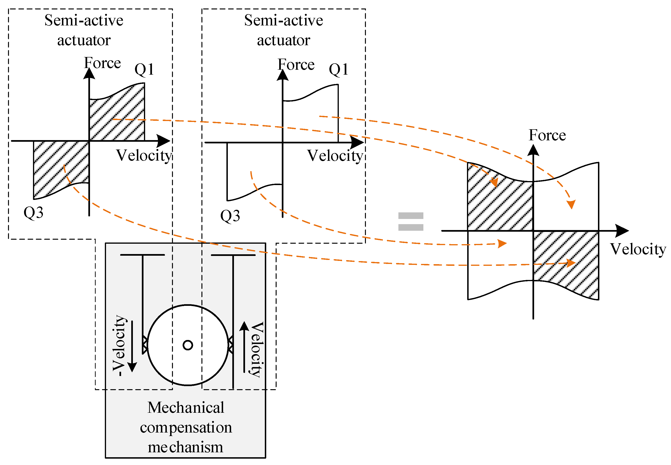
Figure 1, negative stiffness contributions can be combined with a semi-active actuator to approach full-quadrant force generation r while substantially reducing energy consumption [
17,
18,
19]. Bai analyzed this concept on the force–velocity plane [
20] and introduced the term “PAA”, which can generate control forces in all four quadrants. Yang investigated PAA implementations that combine negative stiffness elements with semi-active dampers and experimentally demonstrated favorable performance using a ring-magnet arrangement together with a semi-active damper [
21]. Based on the mechanical characteristics of the PAA, Chen proposed a realization using a mechanical compensation mechanism and verified full-quadrant force generation [
22]. Qiu redesigned the mechanical network of a PAS, demonstrated its feasibility for vehicle suspension applications, and further confirmed through component-level prototype experiments that PAS can outperform semi-active suspensions [
23]. In this paper, the term pseudo-active refers to the equivalent output behavior of a composite actuator, rather than the actuation principle of each internal element.
However, studies that integrate PAAs into a complete vehicle suspension system and report experimental validation remain limited. Meanwhile, ongoing research continues to explore new suspension architectures and controller designs that are grounded in practical vehicle layouts while moving beyond conventional configurations [
21,
22,
23,
24,
25,
26]. For example, Abolfathi achieved a quasi-zero-stiffness (QZS) effect in a vehicle suspension by designing a QZS structure and investigating its isolation performance under realistic road excitations [
27]. For the series active variable geometry suspension (SAVGS), Georgiou proposed a robust model predictive control (RMPC) scheme to address limitations introduced by linearized equivalent models [
28].
To address the above issues, this paper develops a PAS architecture for BoF vehicles based on the working principle and structure of the PAA. The frame is utilized as an approximate ground reference for the mechanical compensation mechanism, and basic geometric design guidelines are also presented. Focusing on a quarter-car PAS configuration, a three-mass dynamic model comprising the sprung mass, the BoF chassis mass, and the unsprung mass is established and formulated in state-space form. On this basis, a conventional full-frequency H∞ controller and a finite-frequency H∞ controller operating over a specified frequency band, both compatible with the model’s input matrix, are designed. Comparative simulations under multiple excitation inputs were performed. Finally, a quarter-car PAS prototype test system and a real-time control platform are developed, and experiments are conducted to validate the feasibility and effectiveness of the proposed PAS architecture and controllers.
2. PAA Concept and PAS Design
2.1. Concepts of PAA and PAS
As shown in
Figure 2, the PAA consists of two parallel adjustable-damping actuators and a mechanical compensation mechanism. One actuator is connected to the input interface; its input end is also connected to the compensation mechanism. The other actuator is not directly connected to the input interface; instead, it is connected to one side of the mechanical compensation mechanism. Both actuator output ends are attached to the sprung mass. Consequently, with respect to the rotational center of the compensation mechanism, the lower ends of the two adjustable-damping actuators undergo motions of equal magnitude but opposite direction.
Through this arrangement—i.e., the combination of two semi-active (adjustable-damping) actuators and the mechanical compensation mechanism—the PAA reshapes the force–velocity capability of a semi-active actuator from quadrants 1 and 3 to quadrants 2 and 4. As a result, a pseudo-active force can be realized at the output end over the entire force–velocity plane (Q1–Q4). This indicates that, while using semi-active hardware and semi-active-level energy consumption, the actuator achieves an active-level force envelope.
As illustrated in
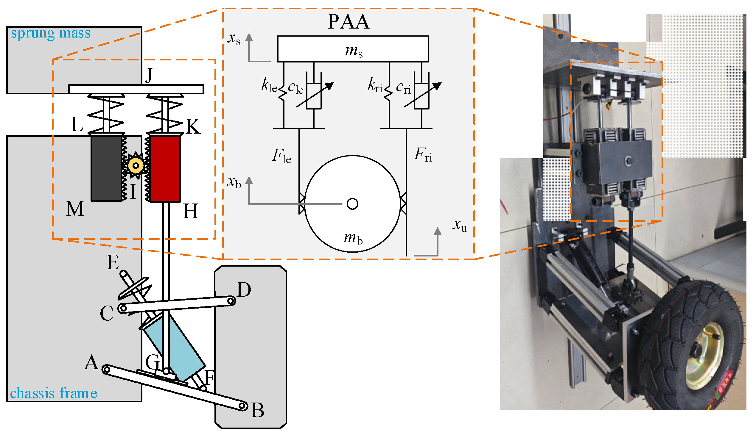
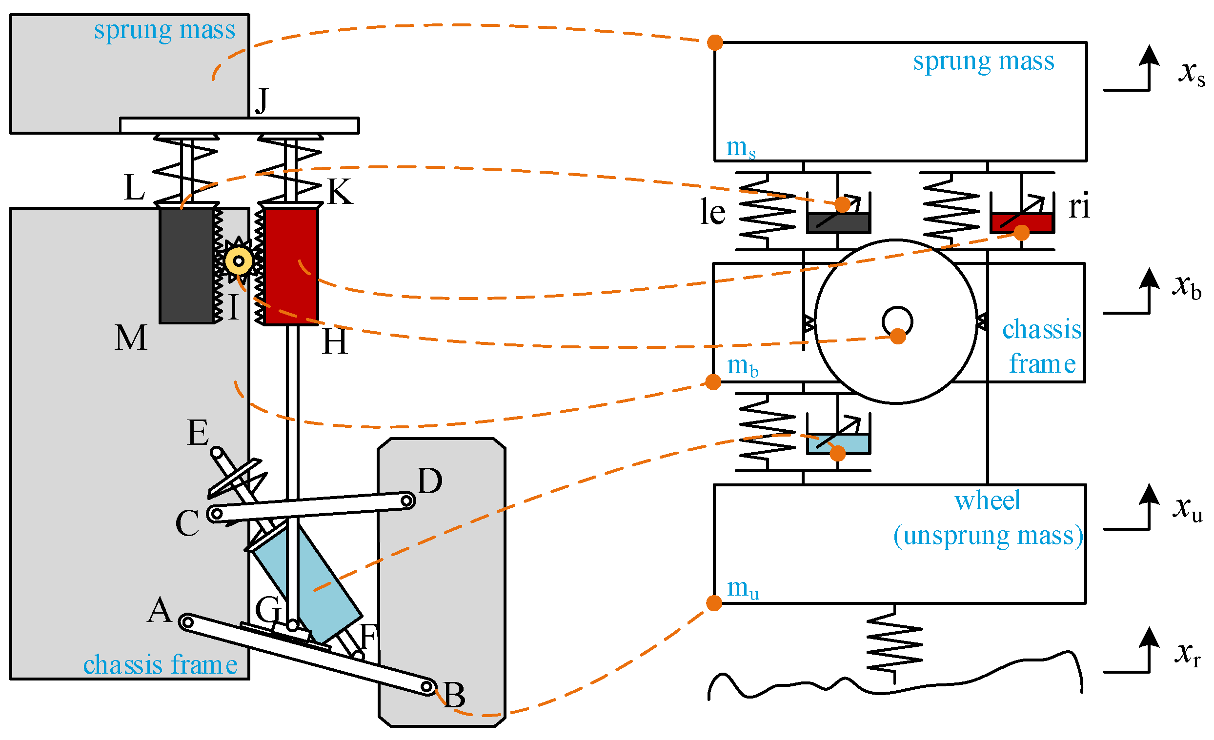
Figure 2, integrating the PAA into a quarter-car double-wishbone suspension of a BoF vehicle yields a quarter-car PAS architecture. In this configuration, the unsprung mass is connected to the BoF chassis through conventional stiffness and damping elements. Meanwhile, the conventional mounting/isolator structures between the sprung mass and the chassis are removed, so that the sprung mass is supported solely by the output end of the PAA. In other words, a PAA-based vibration isolation mechanism is introduced along the load path from the lower control arm to the chassis and then to the sprung mass.
When the lower control arm AB rotates about point A, it drives the slider at point G to translate, thereby pushing the linkage GH associated with the unsprung mass upward or downward. As a consequence, the vibration energy associated with the road-induced displacement input is transmitted to the PAA JMH. The right-branch damper HK, connected to GH, is compressed/extended, and its vertical motion is simultaneously transmitted to the left-branch damper ML through the mechanical compensation structure with point I as the rotational center. This motion relationship is consistent with the mechanical characteristics required by the PAA shown in
Figure 2.
By exploiting the relatively large mass and small displacement of the BoF chassis so that it can serve as an approximate ground reference, the proposed design decouples the sprung-mass structures (e.g., cabin and cargo bed) from the chassis and supports them exclusively via the PAA for vibration isolation. Consequently, ride comfort can be improved without incurring the energy consumption typically associated with fully active suspensions.
In the dynamic model of the PAA, when the mechanical compensation mechanism is assumed to be grounded (i.e., with effectively infinite mass and negligible displacement) and rigidly connected to the output end (i.e., the sprung mass), the resulting output force,
FPA, can be expressed as:
where
cri,
cle,
kri, and
kle are the damping and stiffness coefficients of the right and left branches of the PAA, respectively, and
xu is the input-end displacement of the PAA.
When the mechanical compensation mechanism remains grounded (infinite mass and near-zero displacement), but the rigid connection between the compensation mechanism and the output end (sprung mass) is removed, the resultant output-end force
FPA is given by:
where
xs is the output-end displacement of the PAA.
The corresponding input-end force
Finpt is given by:
By setting ms → 0, the entire mechanism can be equivalently represented as two twin-port elements sharing a common grounded terminal, namely, an input-to-ground element and an output-to-ground element. These two-port elements satisfy the constitutive requirements of mechanical network components.
Based on Equations (2) and (3), performing a power integral over time yields the input mechanical energy expressions of these two elements, as given by:
where
Woupt is the input mechanical energy of the ground-to-output element, and
Winpt is the input mechanical energy of the ground-to-input element.
According to Smith’s definition, the input mechanical energy of the input-to-ground port is non-negative, indicating that this port exhibits passive/semi-active behavior. In contrast, the output-to-ground element contains differential terms as well as the mechanical-compensation channel term. Therefore, when the displacement and velocity at the output end are controlled, the value of Woupt can span the entire set of real numbers. Since Winpt ≥ 0, it follows that Woupt ∈ ℝ and Winpt ∈ ℝ ≥ 0.
Consequently, the output port exhibits the characteristics of an active element and is capable of delivering energy outward, which implies that the output end of the PAA possesses an equivalent active behavior.
2.2. PAS Functionalities and Comparison with Active/Semi-Active Suspensions
In principle, a PAS decouples the input energy level from the achievable force envelope. Its energy consumption can remain at a semi-active level in most operating conditions by improving how efficiently road disturbance energy is attenuated, while its mechanical coupling enables near active-level forces to be generated under specific conditions.
More specifically, semi-active suspensions improve vibration isolation mainly by modulating damping (and related parameters). In this case, external energy is used to adjust the damping level rather than to directly counteract vibration. The proposed PAS inherits this advantage: it uses semi-active actuators as its fundamental components and does not rely on direct energy injection to suppress vibrations, thereby keeping the overall energy demand on the same order as that of conventional semi-active suspensions. This property supports practical implementation while enabling improved body-motion control in the low-to-mid frequency range.
Accordingly, the PAS achieves a near active-level force generation range while requiring only semi-active-level energy demand, which constitutes the primary advantage and core value of the PAS concept.
Moreover, the PAS developed in this study can be integrated into existing suspension layouts with minimal structural changes, enabling practical deployment rather than serving only as a conceptual demonstration. The PAA is installed along the load path between the sprung mass, the chassis, and the unsprung mass to support baseline suspension layouts, including double-wishbone and MacPherson configurations, without interfering with other essential vehicle functions such as steering and braking.
3. PAS Quarter-Car Implementation
This section presents the practical implementation of the PAS in a quarter-car suspension system. It mainly covers: (1) the geometric constraints and design of the interface between the PAA input end and the unsprung-mass-side element; and (2) the application of the PAS to a quarter-car BoE suspension test rig with a double-wishbone architecture.
3.1. PAS Geometric Design
To integrate the PAA into a quarter-car BoF suspension, the architecture introduced in
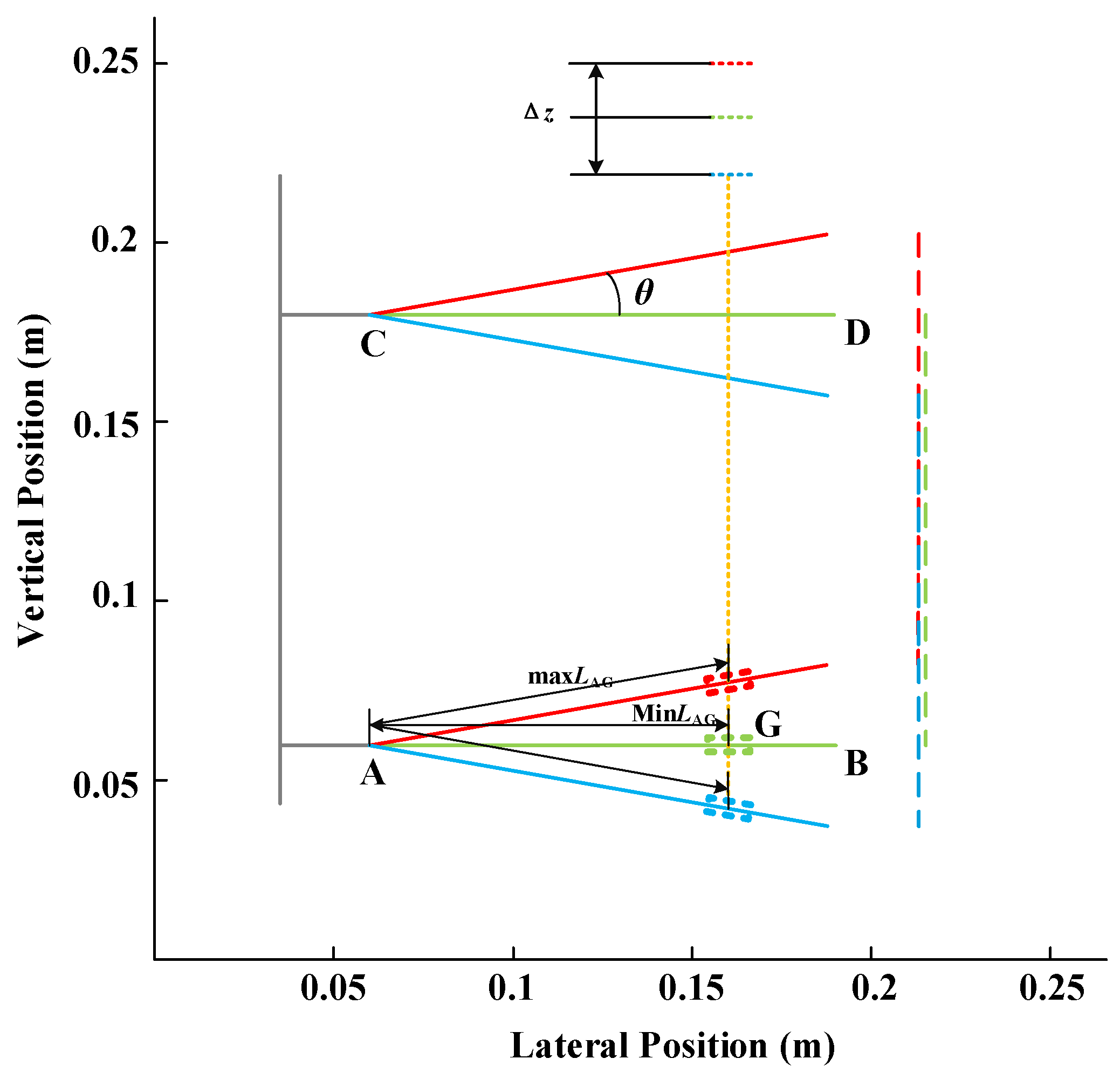
Section 2.2 is implemented with the PAA arranged vertically. In this design, the projection of the PAA input end onto the lower control arm AB corresponds to point G. During suspension motion, arm AB rotates about point A, and its orientation varies with the rotation angle
θ; therefore, point G continuously slides along AB throughout the motion. Therefore, a slider-rail mechanism is introduced on AB to accommodate this relative motion.
A Cartesian x-z coordinate system is established in the primary motion plane of the lower control arm. The unit vector associated with the positive direction of
θ is defined as:
When arm AB is in its horizontal position, the x-coordinate of point G (i.e., the projection of the PAA input end) is denoted as xG0. During the subsequent motion, as θ varies, the sliding point G must always satisfy the fundamental constraint xG = xG0.
Let s(
θ) denote the position parameter of point G along AB. The coordinates of G can then be expressed as:
Since G is required to remain the projection point of the PAA input end, the above horizontal constraint leads to:
Accordingly, the corresponding vertical displacement of point
G is obtained as:
As shown in
Figure 3, when the control arm AB rotates from the lower stop to the upper stop, the rotation angle varies within the range
θ ∈ [
θmin,
θmax]. The travel range of point G along AB, denoted by Δ
s, is given by:
Therefore, the rail length
Lrail installed on AB should satisfy:
where
ssafe is a safety margin.
In the vertical direction, the displacement range of point G, denoted by Δ
z, is given by:
Hence, the stroke of the PAA should be no less than the maximum value of Δz.
3.2. PAS Hardware Design
Based on the concepts and the key dimensional constraints derived in
Section 2.2 and
Section 3.1, a quarter-car PAS test system that emulates a practical vehicle suspension was developed.
As shown in
Figure 4, the PAA is integrated into a three-mass BoF suspension system with a double-wishbone architecture. The PAA input end is connected via a linkage to the lower end of the right-branch damper and TO the lower control arm. In addition, a conventional controllable damper is installed between the lower control arm and the chassis mass to provide baseline load support and vibration attenuation. To satisfy the geometric constraints discussed above, a slider-rail mechanism is incorporated on the lower control arm.
The reversing gear shaft and the frame of the mechanical compensation mechanism are rigidly mounted to the BoF chassis mass, whereas the PAA output end is attached to the sprung mass. As can be observed, no additional mounting/isolator structure is used between the sprung mass and the chassis; the connection is realized solely through the PAA. To emulate different mass, stiffness, and damping configurations, both the chassis mass and the sprung mass are equipped with mounting locations for additional masses (e.g., to represent different curb weights and chassis-to-sprung mass ratios). All three dampers (one at the chassis location and two within the PAA) are magnetorheological dampers, and the helical springs at various locations can be replaced as required.
Furthermore, all masses translate vertically along a vertically mounted linear guide via sliders. To acquire the motion states of each mass, three displacement sensors are installed for measurement. The entire hardware setup is excited by a single-axis shaker table at the base, which is used to emulate the road displacement input.
Overall, from the standpoint of the mechanical layout, the proposed PAS configuration achieves improved compactness and stronger load-support capability (through the introduction of multiple stiffness elements), while avoiding irreversible or destructive modifications to the original BoF suspension architecture.
4. PAS Quarter-Car Dynamic Model and Controller Design
This section develops the dynamic model of the quarter-car PAS. Specifically, a three-mass framework, comprising the unsprung mass, the BoF chassis mass, and the sprung mass, is adopted as the basis. Consistent with the PAS architecture established in the preceding sections, the dynamic model of the PAA is integrated into this framework, incorporating the necessary stiffness and damping elements, disturbance inputs, and relevant geometric parameters. As a result, a complete dynamic model of the quarter-car PAS is derived.
In this study, the
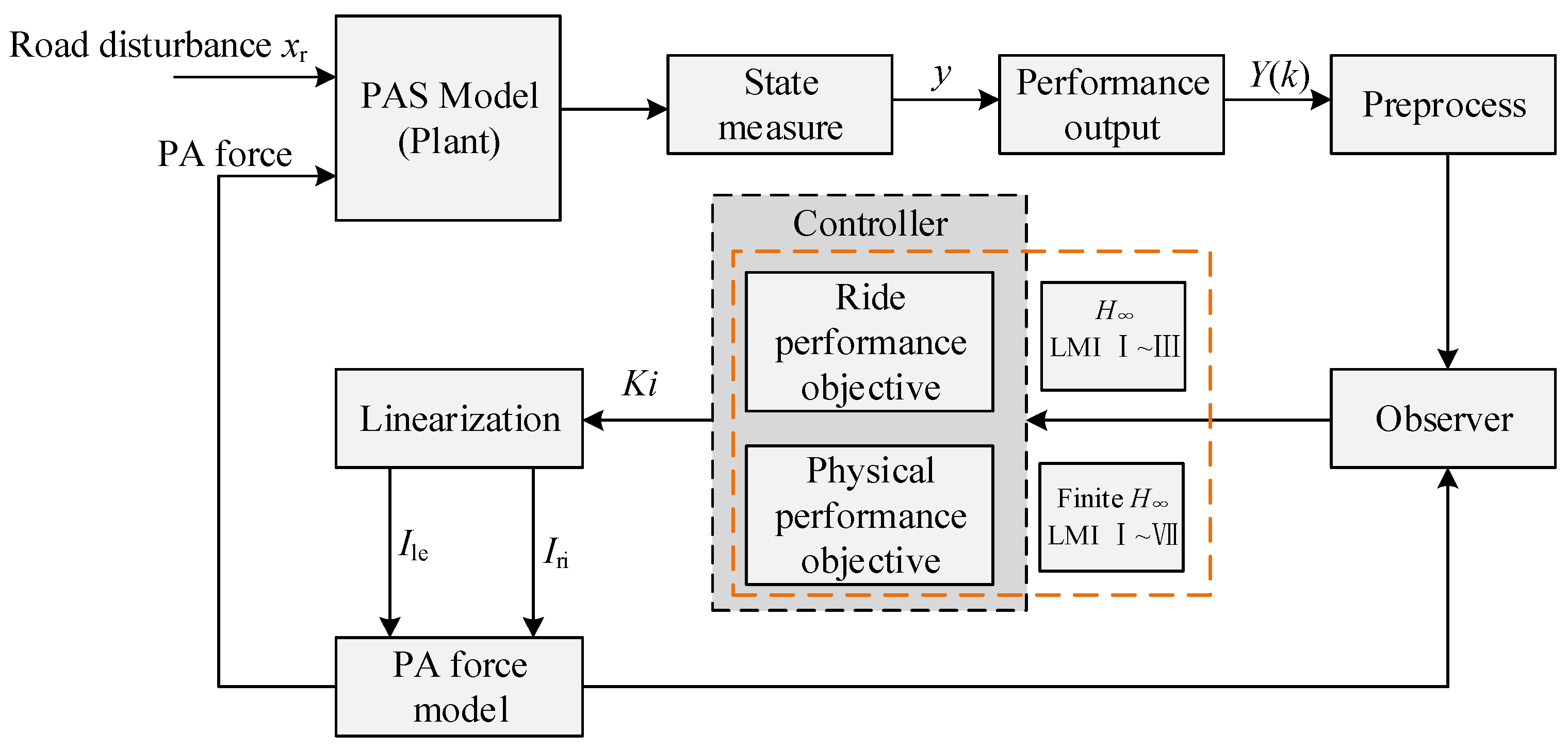
H∞ controller is adopted because the proposed PAS is inherently disturbance-driven and multi-objective. The control task requires simultaneously improving ride comfort (sprung mass acceleration) while enforcing safety-related bounds on dynamic suspension deflection, dynamic tire deflection, and chassis acceleration under actuator limitations. By treating these performance indices as regulated outputs, the
H∞ provides a systematic way to minimize the induced gain from road disturbance to these outputs under actuator limits. So, as shown in
Figure 5, based on the derived PAS dynamic model, an
H∞ controller is developed for vibration control and performance optimization, with the primary objective of improving ride comfort. Furthermore, building upon the conventional full-frequency
H∞ controller, a finite-frequency
H∞ controller with enhanced band-specific control capability is introduced [
29,
30,
31], and its effectiveness for optimizing the vibration control performance of the proposed system is established and investigated.
4.1. PAS Dynamic Model
As shown in
Figure 6, the displacements of the three-mass system are defined as the sprung-mass displacement
xs, the chassis mass displacement
xb, the unsprung-mass displacement
xu, and the road input displacement
xr. The corresponding masses in the PAS are denoted by
ms (sprung mass),
mb (BoF chassis mass), and
mu (unsprung mass). The stiffness and damping coefficients of the left branch of the PAA are
kle and
cle, respectively, while those of the right branch are
kri and
cri, respectively. The stiffness and damping coefficients of the damper between the chassis and the unsprung mass are
k0 and
c0, respectively. Also, the damping coefficient is set to
cpass when it is used for the passive suspension case. The tire stiffness is
kt.
In the PAA, the damper displacement on the right branch connected to the unsprung mass,
xri, is equal to the direct displacement of the unsprung mass, as given by:
Since the right-branch displacement relative to the chassis is
xrack =
xu −
xb, the gear of the mechanical compensation mechanism with radius
rrack is driven by the right branch to rotate by an angle
θrack, which satisfies
θrack =
xrack/
rrack. Therefore, for the left branch that is not connected to the unsprung mass, its displacement relative to the mechanical compensation mechanism has the same magnitude but the opposite sign to that of the right branch, i.e., −
xrack = −(
xu −
xb). Consequently, the absolute displacement of the left branch,
xle, is given by:
Accordingly, the equivalent relative displacements of the left and right branches are obtained as:
In addition, the relative displacement between the chassis and the unsprung mass is expressed by:
The tire elastic deflection is given by:
The forces in the system, namely the left-branch PA force
Fle, the right-branch PA force
Fri, the chassis-unsprung damping force
F0, and the tire force
Ft, are expressed in:
In this study, the left- and right-branch forces are realized using two MR dampers whose damping forces are regulated by controlling their damping coefficients. For each MR damper, the damping coefficient satisfies . Under this condition, the PAA force should satisfy the fundamental upper and lower damping-force bounds for any branch relative velocity.
Using the Lagrange formulation, the kinetic energy
and potential energy
of the PAS system are constructed as shown in:
and the dissipation function
is obtained as:
Therefore, for the generalized coordinates
x1 ∈ {
xs,
xb,
xu}, the Lagrange equation is written as:
Accordingly, the differential equations of motion of the sprung mass, the chassis mass, and the unsprung mass in the PAS are given in:
The corresponding passive spring forces are
Fk,le =
kleδle and
Fk,ri =
kriδri. Since the two MR dampers are semi-active devices whose damping level is regulated by current, we treat their controllable damping-force components as the control inputs:
ule =
cle,
uri =
cri. With these definitions, Equation (25) can be equivalently rewritten as:
The state vector and the output vector of the PAS are defined in:
Using the state vector defined in Equation (27),
, can be solved from Equation (26) and expressed linearly in terms of the states and the input vector
u = [
ule,
uri]
T, yielding the representation:
Let the damping forces of the left- and right-branch dampers in the PA, Fle and Fri, be selected as the control inputs. The input vector is thus defined as u = [ule, uri]T, and the road disturbance input is taken as . Let z1 = xs − xb, z2 = xu − xb, zt = xu − xr, then xs + xu − 2xb = z1 + z2, xs − xu = z1 − z2.
Consequently,
is obtained.
Moreover, since
xs −
xu =
z1 −
z2,
, the coefficient matrices of the PAS state-space model are described in the
Appendix A.
4.2. Controller Design
4.2.1. H∞ Controller
Since the state vector of the PAS is defined by Equations (27) and (28) in
Section 4.1, and the road disturbance input is
, the ride-comfort optimization objective and the associated constraints for the system in Equation (29) are defined as follows:
- (1)
Ride-comfort objective
The comfort-oriented performance variable is selected as the sprung-mass acceleration, given by:
- (2)
System constraints
The constraints include the dynamic suspension deflection
xs −
xu, the tire relative displacement
xu −
xr that determines the variation of vertical tire load, and the chassis acceleration
. These are formulated as hard constraints
, as expressed in:
where
ρ1,
ρ2, and
ρ3 are the energy weighting coefficients associated with the suspension deflection, tire relative displacement, and chassis acceleration, respectively, and
C2 denotes the hard-constraint output matrix. Moreover, since the selected MR dampers have performance limits, an input constraint is imposed such that the control input does not exceed the maximum admissible control force
umax, as given in:
The full-state feedback law is defined as:
which directly commands the desired controllable damping forces
ule,
uri. Substituting Equation (34) into Equation (29) gives the closed-loop dynamics in Equation (35):
By treating the ride-comfort objective and the system constraints as controlled outputs, Equation (36) is obtained:
Finally, applying the bounded real lemma, we introduce Q > 0 and the change of variables Y = KQ to obtain an LMI that is linear in the decision variables (Q, Y, γ). Minimizing γ gives the gain K1 = YQ−1, which yields the full-band H∞ control matrix K1.
4.2.2. Finite-Frequency H∞ Controller
First, the finite-frequency range
Ω = [
ω1,
ω2], where
ω1 and
ω2 denote the lower and upper bounds of the target frequency band, respectively. Within this specified frequency interval, the system is required to satisfy:
where
Tzω(s) denotes the transfer function from the disturbance
ω to the controlled output, and
γ′ > 0 is a prescribed upper bound on the performance level.
To avoid the bilinear terms that arise when the decision variable
P and the finite-frequency
H∞ control matrix
K2 are directly coupled, an invertible matrix
F is introduced via the substitution in:
Let the decision variables satisfy
P =
P T,
P1 =
P1T > 0,
Q =
Q T > 0,
F ∈ ℝ
(6×6),
K2 ∈ ℝ
(2×6),
rs > 0, where
Q is the band parameter matrix. Given an energy constraint coefficient
η > 0, impose:
Then, at the center frequency
ωc = (
ω1 +
ω2)/2, considering the output
y =
C′
x +
D′
u, the augmented real-valued LMI can be formulated as:
Similarly, to ensure that the control forces satisfy the imposed upper limits, Equation (33) can be adopted. In addition, amplitude constraints are enforced by defining coefficient vectors
e1 = [1, 0, 0],
e2 = [0, 1, 0],
e3 = [0, 0, 1], and introducing constraints on dynamic suspension deflection, dynamic tire load, and sprung-mass acceleration. By applying the constraint:
Based on the generalized KYP lemma, we formulate a finite-frequency H∞ condition and introduce slack variables to remove bilinear terms, resulting in an LMI that is linear in the decision variables. The gain is recovered as Equation (38).
5. PAS Simulations
In this section, simulation studies are conducted for the quarter-car PAS developed in the preceding sections. The disturbance inputs considered include fixed-frequency sinusoidal displacement excitation, swept-frequency displacement excitation, and pulse displacement excitation. The primary objective is to evaluate and compare the ride-comfort performance indices of the PAS under these representative displacement inputs against those of a conventional BoF suspension.
According to ISO 2631 [
32], the human body is particularly sensitive to vibrations in the 4–8 Hz range. Therefore, ride-comfort assessment associated with the sprung-mass response of the suspension is often focused on this frequency band, and the control frequency interval
of the finite-frequency
H∞ controller is set to [4 Hz, 8 Hz].
The remaining key parameters of the PAS are listed in
Table 1.
As shown in
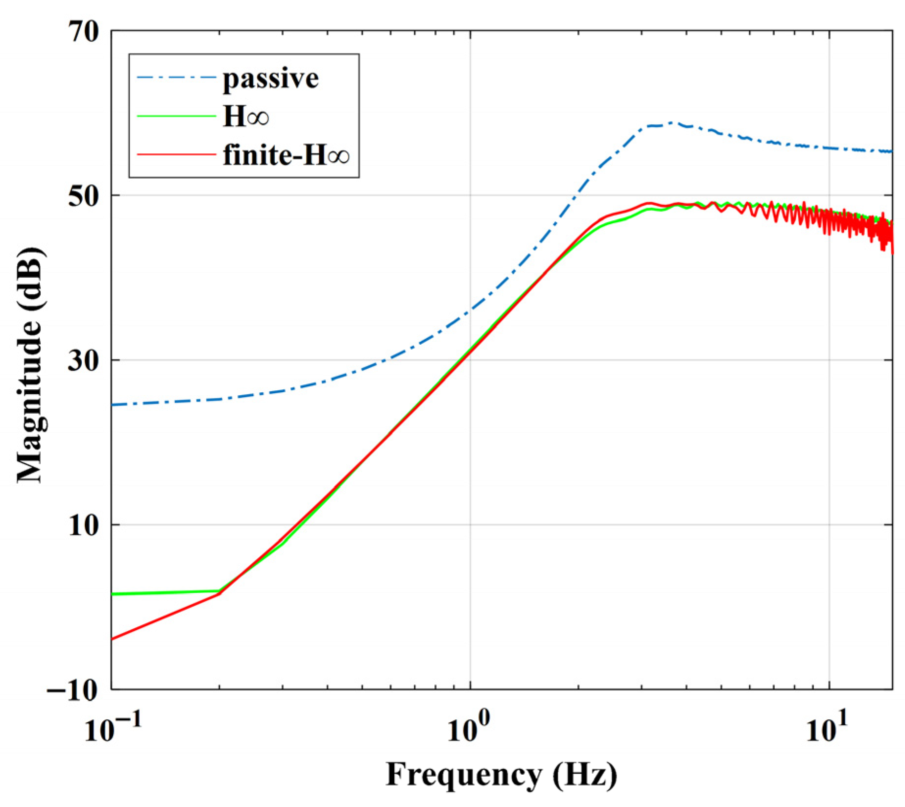
Figure 7, the Bode plots of the PAS under the two controllers and the passive suspension indicate that, under both controllers, the PAS provides pronounced attenuation over 0.1–10 Hz relative to the passive case. Within the target band
, the finite-frequency
H∞ controller achieves a lower response level than the conventional full-frequency
H∞ controller.
As shown in
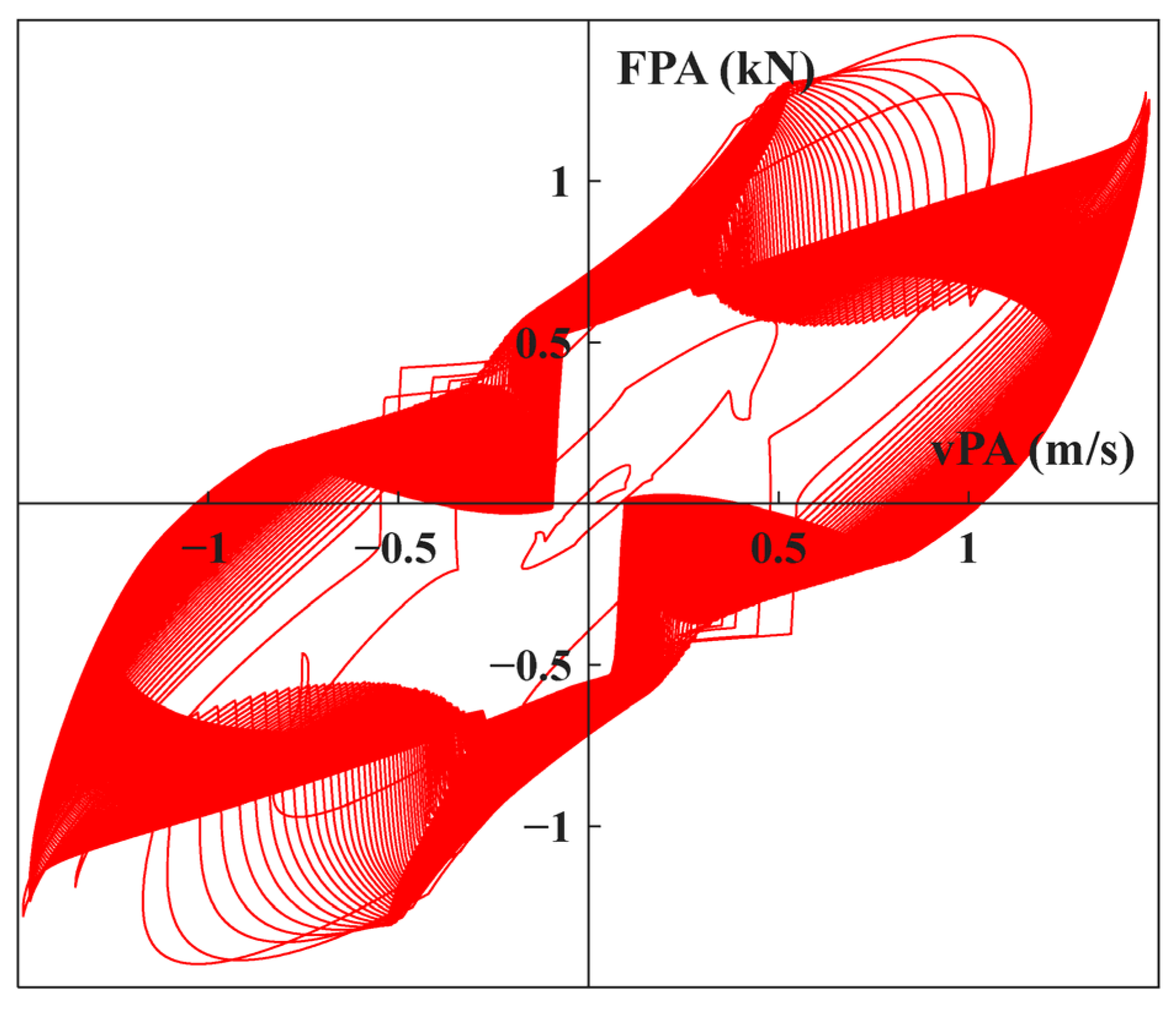
Figure 8, taking the swept-frequency displacement excitation as an illustrative example, the output force of the PAS at the sprung-mass side,
, covers all quadrants in the force–velocity plane. This demonstrates that the PAS can be regarded as producing a full-quadrant “pseudo-active” actuation force.
5.1. Case Study with the Harmonic Input
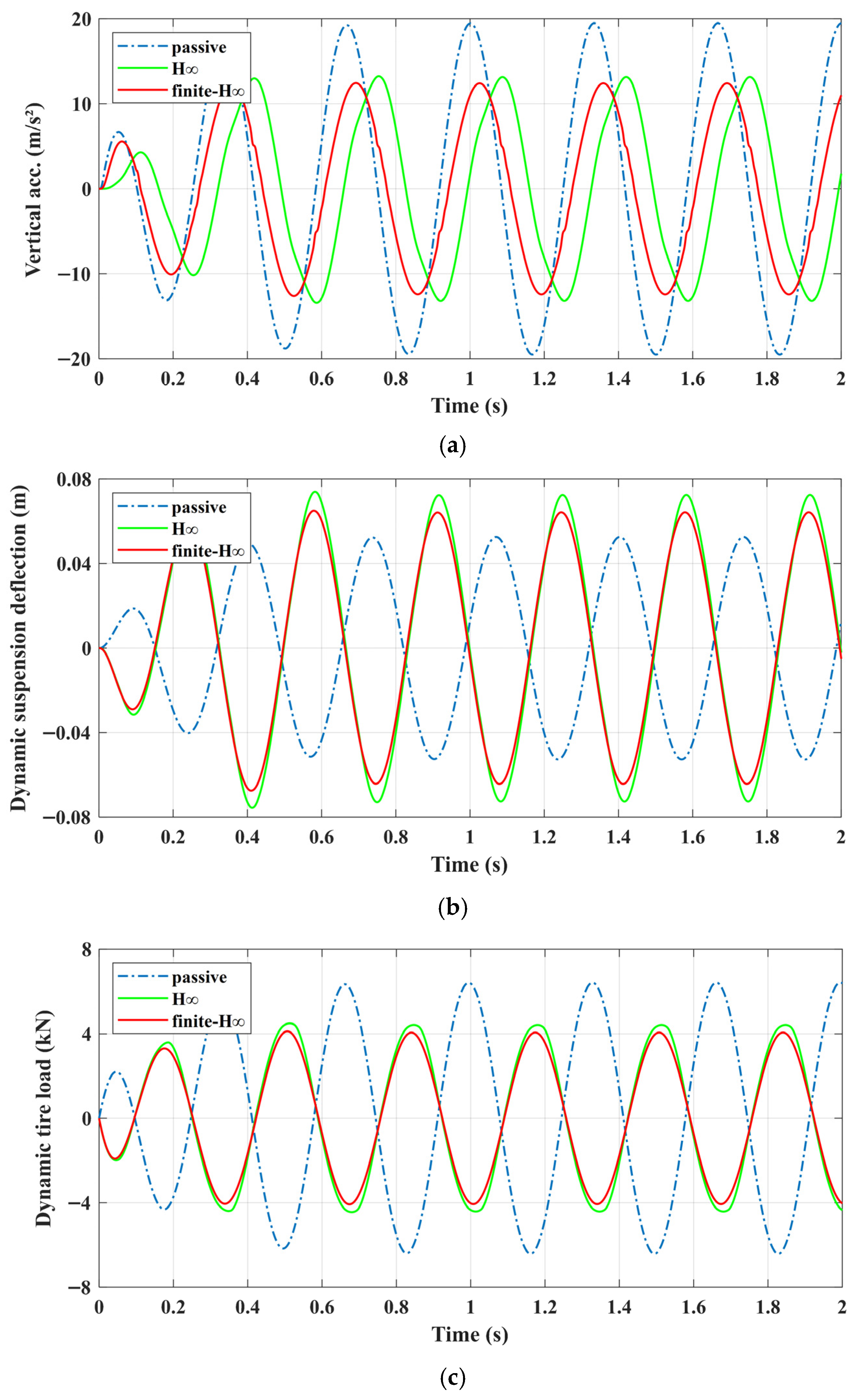
In this simulation study, a sinusoidal displacement input at 6 Hz-i.e., the center frequency of the target band -is applied to the PAS with an amplitude of 0.05 m.
The simulation results are shown in
Figure 9. It can be seen that the sprung-mass acceleration is substantially improved by the PAS. Moreover, within the prescribed frequency interval, the finite-frequency
H∞ controller further reduces the sprung-mass acceleration by a certain margin compared with the conventional full-frequency
H∞ controller. Specifically, relative to the baseline BoF suspension, the two PAS controllers reduce the peak sprung-mass acceleration by 32.19% and 36.27%, respectively, and reduce the dynamic tire load by 20.91% and 27.35%, respectively, at the expense of increased dynamic suspension deflection.
5.2. Case Study with the Pulse Input
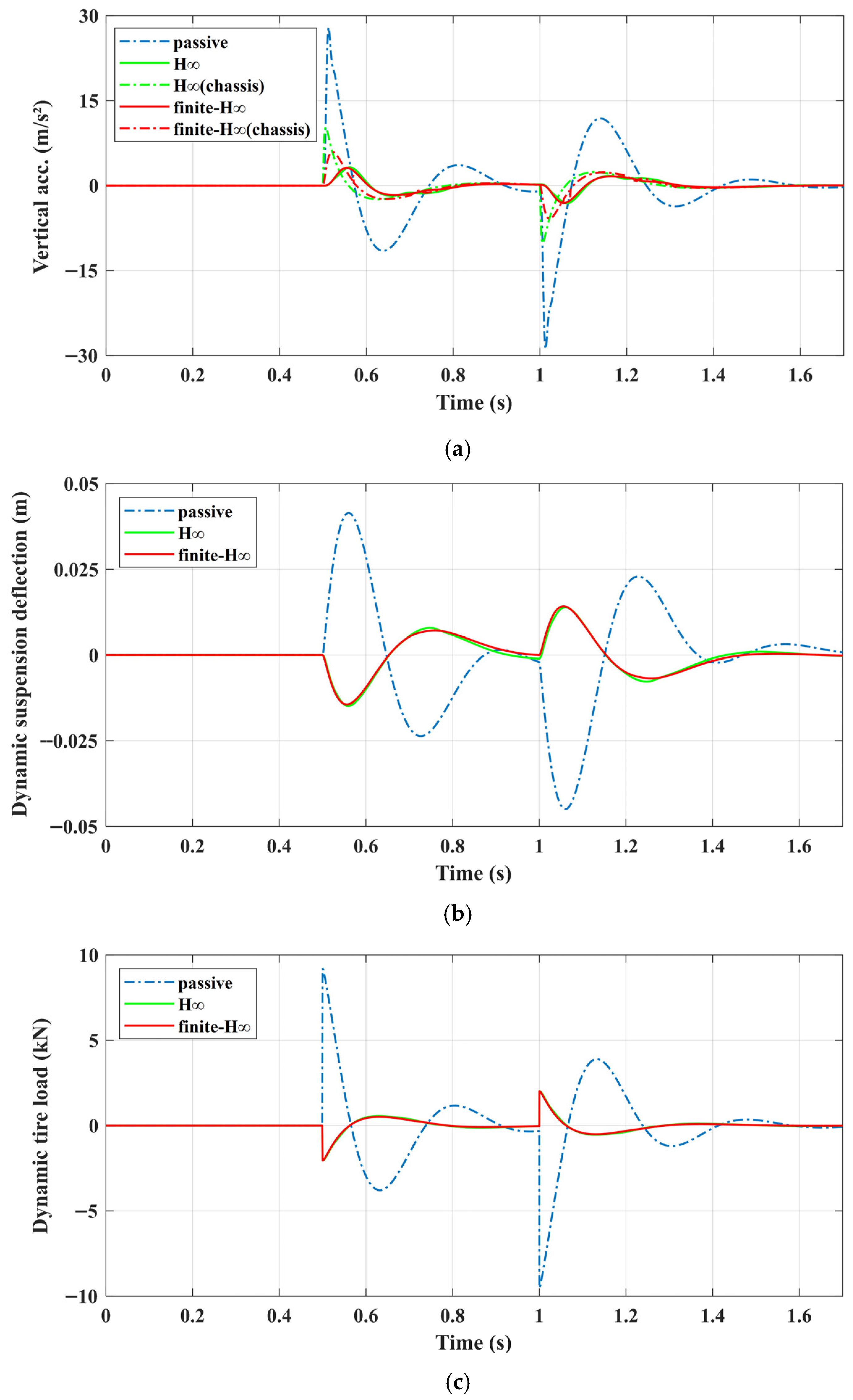
Since vehicles frequently encounter pulse-type displacement disturbances during driving, a square-wave input with an amplitude of 0.05 m is used to emulate road irregularities.
The corresponding simulation results are presented in
Figure 10. The PAS is observed to significantly suppress the transmission of pulse-induced energy throughout the system. In particular, the peak sprung-mass acceleration is reduced by more than 60% compared with that of the baseline BoF suspension, which also substantiates the benefit of removing the conventional mounting/isolator structure between the chassis and the sprung mass in the proposed PAS design.
5.3. Case Study with the Swept-Sine Input
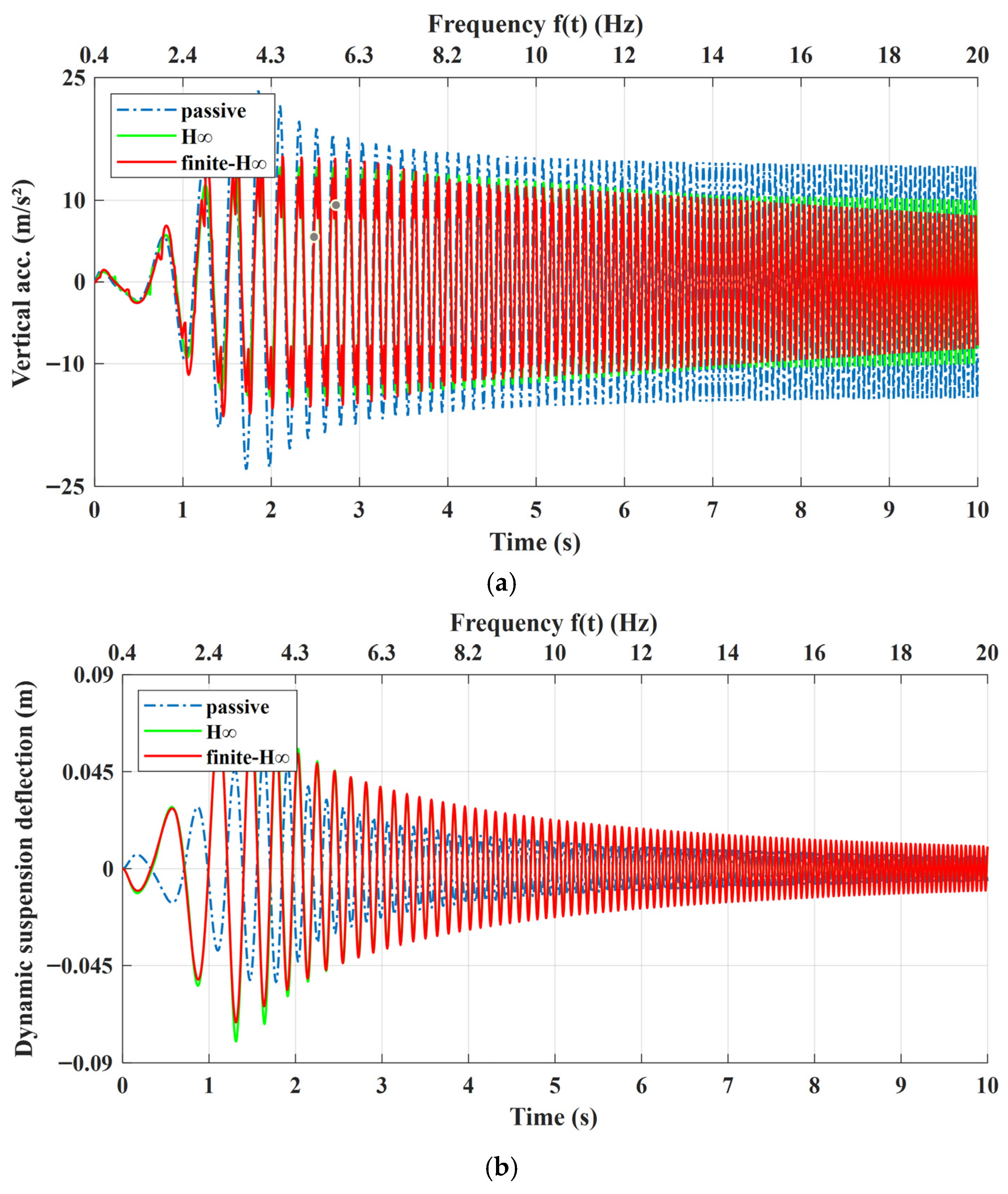
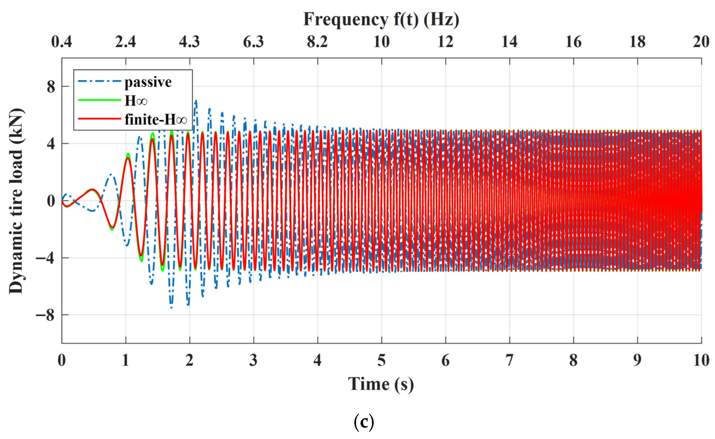
To further examine the band-specific performance of the finite-frequency H∞ controller within the prescribed finite-frequency range, a swept-sine displacement excitation with an amplitude of 0.05 m and a frequency varying from 0.4 to 15 Hz is applied.
The simulation results are shown in
Figure 11. Compared with the conventional suspension, the PAS achieves a pronounced reduction in sprung-mass acceleration. Within 4–8 Hz, the finite-frequency
H∞ controller exhibits a response similar to that of the full-frequency
H∞ controller during the early stage of the sweep (around 0.4 Hz), while further suppressing acceleration as the excitation frequency approaches 4 Hz. As noted above, this improvement is also achieved at the cost of increased dynamic suspension deflection in the PAS. It is worth noting that, under the swept input, the second resonance that would normally be expected to appear in the time-domain response (
Figure 11) is not pronounced. The main reason is that the sprung mass of our passive suspension is defined as
meq =
mb+
ms after removing the body-mount isolation. With the relatively large mass ratio between
meq and the unsprung mass
mu, together with the presence of passive damping, the second-mode (wheel-hop) resonance is weakly transmitted and therefore difficult to clearly observe in the response.
6. PAS Experiments
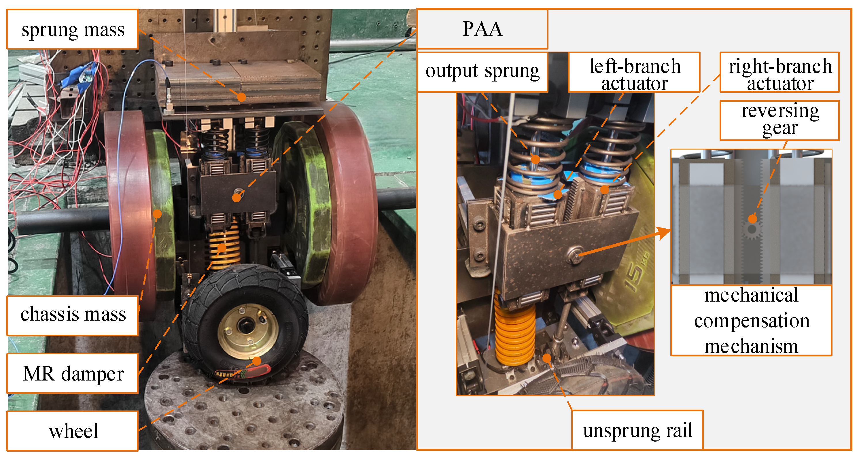
In this section, an experimental test system for the quarter-car PAS is developed. As shown in
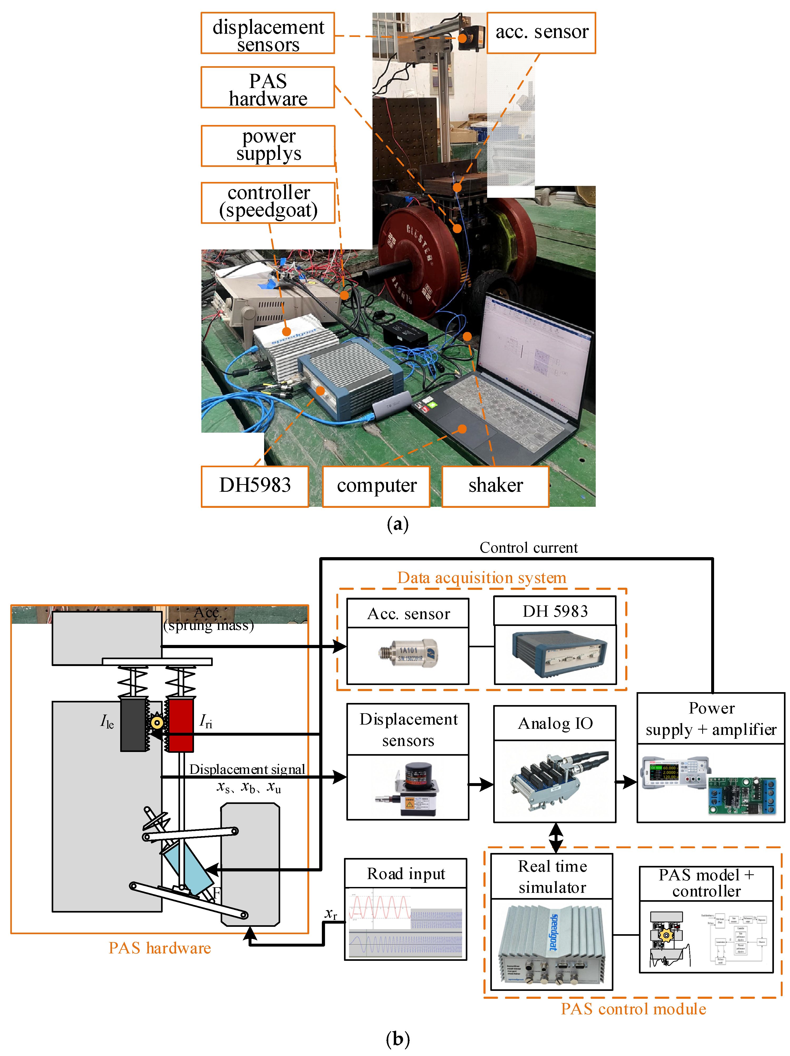
Figure 12, three displacement sensors are employed to measure the displacements of the unsprung mass, the BoF chassis mass, and the sprung mass, respectively. These sensors are mounted in parallel with the linear guide of each mass to directly capture the vertical translation. The measured displacements
xb,
xs,
xu are used to form the relative displacement states exactly as defined in Equation (27). The velocity states
required by Equation (27) are obtained online from displacement measurements using a discrete differentiation scheme with appropriate filtering to suppress noise. A single-axis shaker table is used to generate the displacement excitation input. The state signals are acquired via the IO191 module of a Speedgoat real-time target, based on which the control commands are computed online. At each control step, the state vector
x is assembled according to Equation (27), then Equation (34) is evaluated to generate the commanded control input
u = [
ule,
uri]
T, which corresponds to the commanded controllable forces of the left- and right-branch MR dampers. The currents of the two MR dampers within the PAA, as well as the current of the independent MR damper between the unsprung mass and the chassis, are then regulated in real time using an identified force–current inverse model.
With respect to the experimental conditions, displacement excitation scenarios similar to those in
Section 5 are designed. In addition, an independent data acquisition system is used to measure the time-domain acceleration signal of the sprung mass. It is worth noting that, to provide more informative benchmark results, a semi-active control strategy is also implemented on the independent MR damper in this test campaign, thereby enabling an assessment of the advancement of the proposed PAS architecture and its corresponding controllers.
Specifically, the quarter-car PAS test system is evaluated using the full-frequency
H∞ controller and the finite-frequency
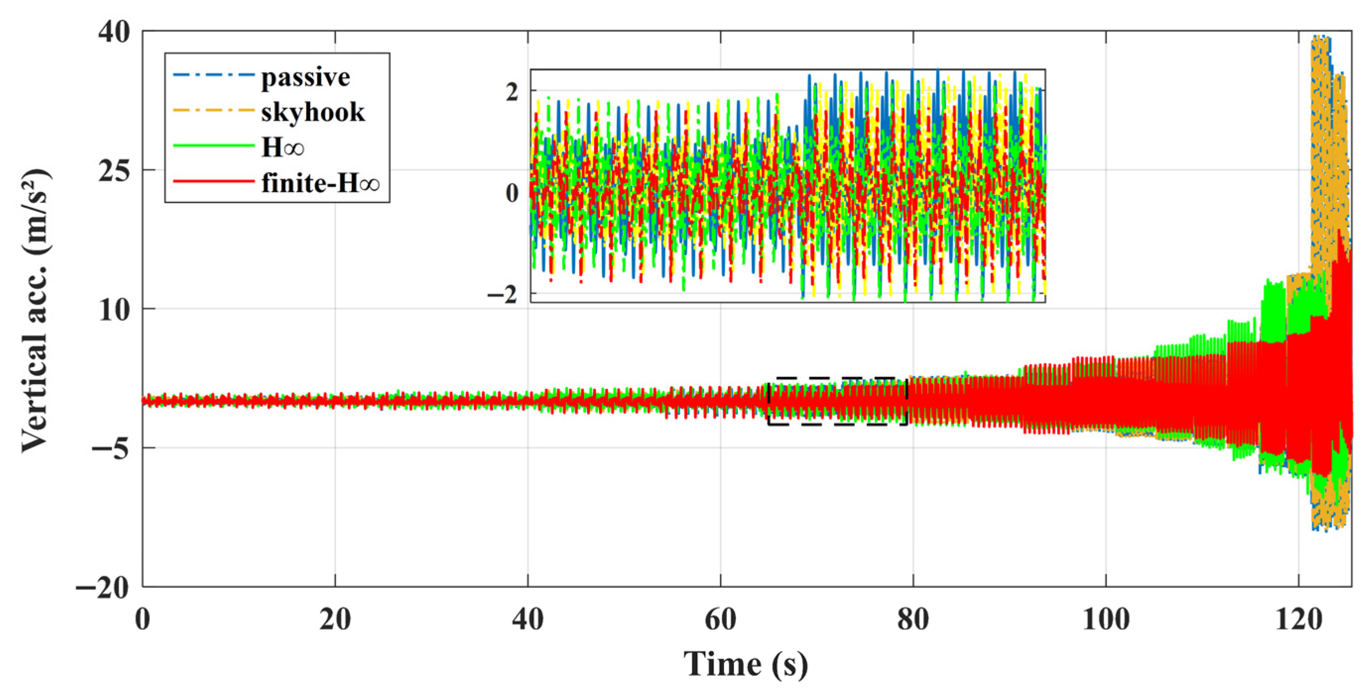
H∞ controller. For the baseline suspension, a semi-active suspension with a skyhook controller is adopted for comparison, in addition to the passive case. The test inputs include (i) a sinusoidal displacement excitation at 4.5 Hz with an amplitude of 0.1 m and (ii) a swept-frequency displacement excitation starting from 0.4 Hz with step sizes of 0.2 Hz (0.4–3 Hz) and 0.5 Hz (3.5–
fmax), where
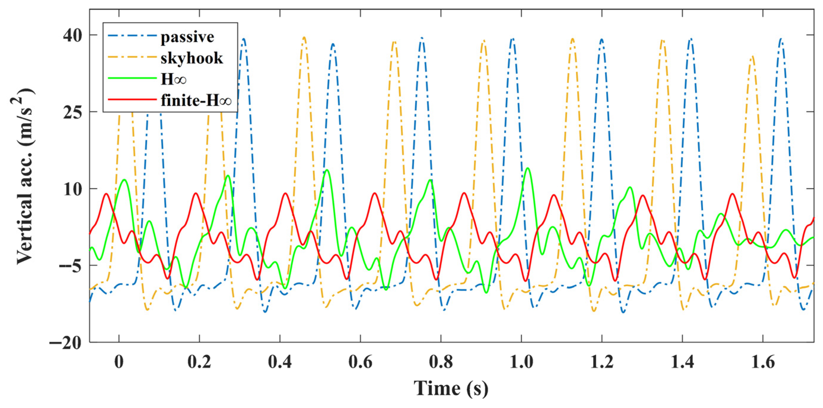
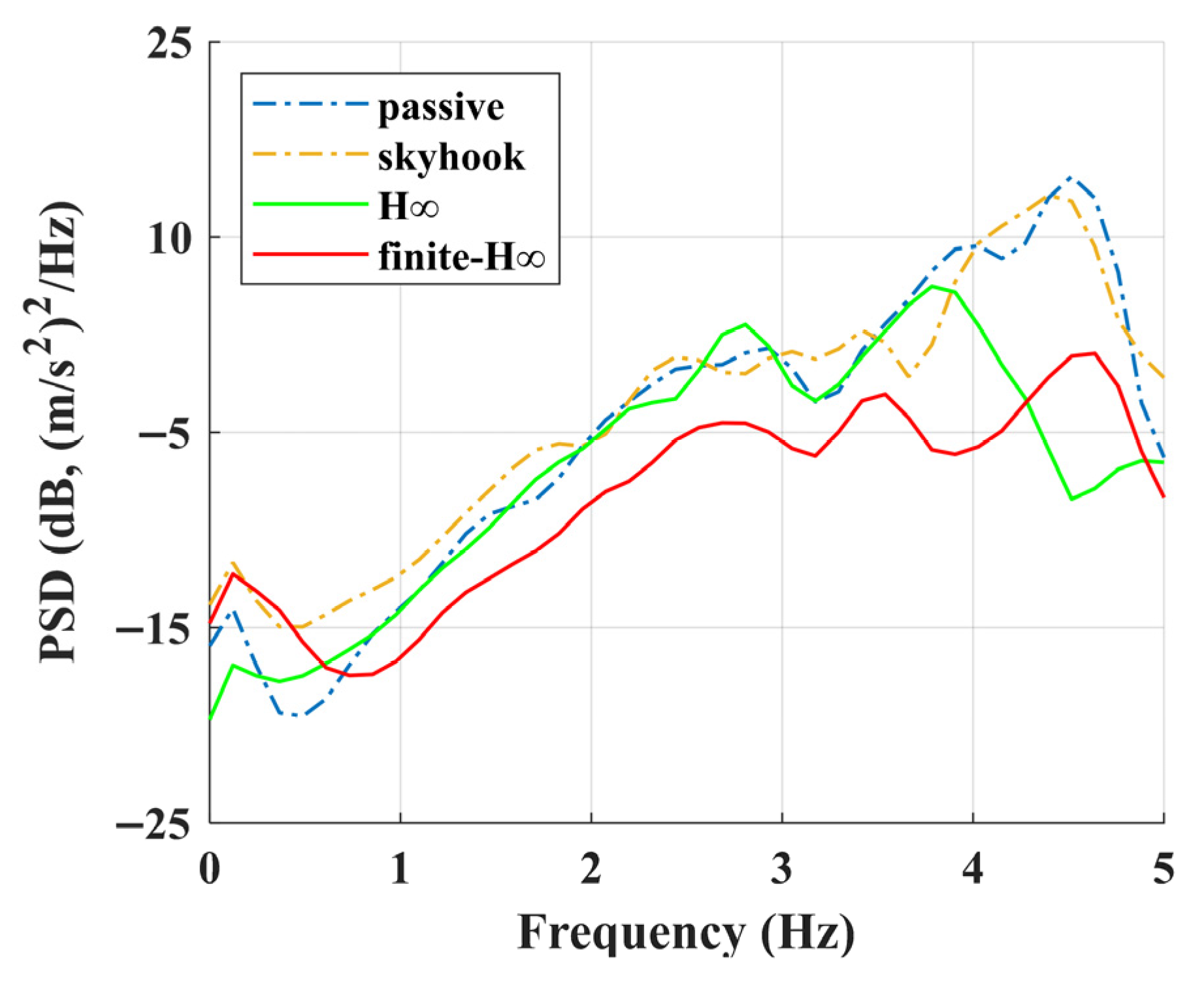
fmax is the maximum output frequency achievable by the shaker. The sprung-mass acceleration responses under different controllers and excitation inputs are shown in
Figure 13,
Figure 14 and
Figure 15.
The comparative experimental results indicate that, under constant-frequency excitation, the PAS achieves effective attenuation of the sprung-mass vibration acceleration relative to both the passive suspension and the semi-active suspension. Specifically, under the H∞ and finite-frequency H∞ controllers, the PAS reduces the peak-to-peak sprung-mass acceleration by 68.46% and 67.69%, respectively, compared with the passive suspension, and by 54.58% and 53.48%, respectively, compared with the semi-active suspension.
Under swept-frequency excitation, a similar trend is observed: the PAS consistently maintains a lower sprung-mass acceleration. After the excitation frequency exceeds 1 Hz, the advantage of the finite-frequency
H∞ controller becomes evident and persists until the end of the experiment at 5 Hz. A further quantitative analysis shows that, within 4–8 Hz, the finite-frequency
H∞ controller reduces the RMS value of the sprung-mass acceleration by 49.39% and 48.82% relative to the passive and semi-active suspensions, respectively, and achieves more than a 12% improvement compared with the conventional full-frequency
H∞ controller. A consistent relationship can also be observed from the frequency-response results in
Figure 15.
Overall, the experimental results are consistent with the simulation findings: the quarter-car PAS provides superior suppression of sprung-mass vibration compared with conventional passive and semi-active suspensions for a BoF vehicle under various road excitation conditions. Importantly, the control energy input of the entire PAS system remains within the semi-active level, with the peak power not exceeding 50 W. These results indicate that, relative to existing suspension architectures, the proposed PAS can achieve semi-active-level energy consumption while delivering performance superior to both passive and semi-active suspensions.
7. Conclusions
This study proposes a novel quarter-car PAS architecture based on a PAA. Focusing on the integration of the PAA into BoF vehicle suspensions, the proposed system incorporates dedicated geometric optimization and mechanical packaging design. A key concept is to remove the conventional body-mount isolation between the chassis and the sprung mass, so that the sprung mass is supported through the PAA. As a result, a quarter-car PAS with a double-wishbone suspension layout, together with a corresponding test system, is developed.
By addressing the grounding condition of the mechanical compensation mechanism in the PAA and considering the quarter-car three-mass dynamics of BoF vehicles, a dynamic model of the quarter-car PAS is established. Considering the left- and right-branch control inputs of the PAA, a matched H∞ control design is formulated. This resolves a key limitation in related studies, where general solutions for realizing PAA control forces within suspension mechanisms were not available. Furthermore, a finite-frequency H∞ controller operating over a specified frequency band is introduced for the PAS to further enhance control effectiveness.
Simulation results indicate that, compared with a conventional passive BoF suspension in which the chassis and sprung mass are coupled via mounts, the proposed PAS achieves lower sprung-mass acceleration under constant-frequency sinusoidal, pulse, and swept-frequency excitations, thus improving ride comfort. Among the evaluated controllers, the finite-frequency H∞ controller, whose operating band is selected to coincide with the human sensitivity range, exhibits the best performance. This improvement can be attributed to retaining more vibration energy in the chassis mass, which is also consistent with the increased suspension deflection observed in the simulations. Meanwhile, the PAS does not lead to a significant deterioration in dynamic tire load. Importantly, these benefits are achieved with semi-active-level energy consumption.
We conducted experiments on the developed PAS test rig. The results demonstrate that, under swept-frequency and sinusoidal displacement inputs, the PAS preserves the predicted advantages. Both the conventional full-frequency H∞ controller and the finite-frequency H∞ controller improve performance relative to the baseline suspension. Moreover, compared with an additional semi-active benchmark, the PAS also provides improved ride-comfort performance.
By combining the PAA with existing suspension architectures, the proposed PAS leverages the mechanical properties of the PAA to improve ride comfort without substantially increasing structural complexity or energy consumption in BoF suspensions. As a novel vehicle suspension architecture, PAS can deliver improved performance, but it also has certain limitations. Since PAS requires adding additional components, such as a mechanical compensation mechanism, into a conventional BoF suspension layout, practical vehicle implementation must carefully consider packaging space, mechanism travel, and interference/clearance checks. Therefore, the structural design of PAS should be incorporated into the overall vehicle design from an early stage, rather than being retrofitted onto an existing conventional layout; otherwise, its achievable performance may be constrained, and additional structural issues may even be introduced. Overall, the simulation and experimental results support the feasibility of the proposed approach, and they also motivate further exploration of PAAs in related applications.
8. Patents
The PAS theory, mechanism, and its testing system mentioned in this article have been applied for a Chinese patent, ID. CN121157552A.