1. Introduction
The cooperative control of multiple aircraft has emerged as a significant research area, drawing inspiration from the coordinated behaviors observed in biological groups [
1,
2,
3,
4,
5,
6,
7]. As a cornerstone of artificial intelligence, the cooperative control of multi-agent systems (MASs) has been extensively explored [
8]. Central to this framework is the concept of consensus, notably formalized by Olfati-Saber [
9,
10]. By introducing a distributed control protocol predicated on nearest-neighbor rules, Olfati-Saber demonstrated that systems governed by directed, strongly connected interaction graphs attain asymptotic stability irrespective of their initial states. Assembly, the initial phase of any formation mission, is critical for ensuring a smooth and successful transition into a coordinated formation. Consequently, various strategies have been proposed to address this challenge. These include improving algorithms for rapid assembly [
11], employing time-varying vector fields for simultaneous arrival [
12], optimizing Dubins curve parameters via particle swarm optimization [
13], and using RRT-based path planning with time constraints [
14,
15,
16]. However, a common limitation of these studies is their reliance on simplified, often second-order, aircraft models, which fail to capture the complexities of real-world dynamics and external disturbances. This highlights a critical research gap: the need to investigate assembly processes using high-fidelity aircraft models under realistic interference.
Due to formation changes and airflow interference during formation flight, aerodynamic parameter changes can occur, which can affect the robustness of flight control. To enhance the robustness of control for nonlinear systems, which accurately describe real aircraft, various robust control methods have been proposed. These include Q-learning-based optimal control [
17], observer-based methods for quantized networked systems with stochastic uncertainties [
18] and sliding mode control integrated with Radial Basis Function Neural Network observers for collision-free formation [
19,
20,
21]. Within robust control frameworks, observers are essential for state estimation, particularly when sensor capabilities are limited and the system is subject to disturbances. For instance, fuzzy observers combined with Backstepping have been used for ship heading control [
22], but this approach can suffer from high implementation complexity and relies on simplified system models. Similarly, while observers based on the super-twisting algorithm have been applied to hypersonic aircraft [
23], the inherent sign function in such algorithms introduces a risk of chattering, potentially compromising system stability.
Furthermore, as the assembly process involves aircraft maneuvering in close proximity, collision avoidance is paramount. While methods like the dynamic window approach are suitable for ideal, fully known systems [
24], artificial potential fields (APFs) [
25,
26,
27] are often preferred for systems with uncertainties. However, existing APF-based consensus algorithms that assume a static communication topology [
28] may fail to prevent collisions between aircraft pairs that do not communicate directly. This underscores the necessity of a dynamic, time-varying topology to ensure comprehensive collision avoidance.
To address the challenges, this paper focuses on the problem of cooperative, collision-free formation for aircraft in the presence of external disturbances from formation changes and aerodynamic interference. The main contributions of this work are as follows:
- (1)
We propose an observer-based Backstepping control method to address uncertainties arising from formation changes and aerodynamic interference, thereby ensuring stable and precise low-level control of the aircraft’s attitude and velocity.
- (2)
A novel guidance strategy is developed that utilizes a time-varying topology combined with a three-dimensional position allocation algorithm. This ensures proactive collision avoidance, enabling safe and optimal assembly for aircraft departing from different initial locations.
- (3)
We design a complete set of control laws that guide the aircraft through distinct phases: fixed-point aggregation, accompanying flight, and tight formation. This framework, based on consensus theory, achieves stable and coordinated control throughout the entire assembly process.
The remainder of this paper is organized as follows.
Section 2 details the 6-DoF aircraft dynamics and presents the design of the low-level robust controllers.
Section 3 elaborates on the collaborative assembly guidance strategy.
Section 4 provides simulation results and analysis to validate the proposed method. Finally,
Section 5 concludes the paper.
2. Preliminaries
2.1. Cooperative Assembly Problem Description Translation
Cooperative assembly control for aircraft enables multiple vehicles, starting from any initial state, to establish a designated formation and communication links while adhering to shared constraints on speed, heading, and timing. To accomplish their mission, the aircraft must first assemble into a designated, collision-free formation within a specific airspace. The process begins when the ground station transmits an assembly command. Each aircraft, upon receiving this command, must send back an acknowledgment; if an aircraft fails to receive the command, the ground station will retransmit it. Once the command is acknowledged by all aircraft, the ground station assigns each a unique identifier to facilitate coordination. Next, target assembly points are generated based on each aircraft’s current pose and the desired terminal constraints for a loose formation. These points are then optimally assigned to the individual aircraft. Using these assigned targets and consistency control protocols, individual assembly paths are generated for each aircraft, guiding them to converge into an initial loose formation. Finally, the transition to a tight formation is executed. Through precise trajectory control governed by the consistency protocols, inter-aircraft distances are adjusted and the formation is compressed. This final step completes the entire assembly process.
2.2. Aircraft Dynamics Model
This paper uses a real aircraft model to conduct simulation tests. Through Newton’s second law, the law of torque and the motion relationship between states, a full-state differential model of the aircraft is established. The model of the
aircraft is as follows:
where
are the state variables of the
aircraft,
is the control input, and
and
are the uncertainty of attitude angle, angular rate and external interference error, respectively.
Based on the aircraft model established in the previous section, we proceed to design the low-level control law. Since the collaborative assembly guidance layer generates commands for attitude angle and speed, the controller for each individual aircraft must ensure precise tracking of these variables. To enhance the performance of the inner-loop attitude and angular rate control, we propose integrating an extended state observer (ESO) with Backstepping control. This integration enables the estimation of disturbances and modeling errors by formation changes and aerodynamic interference. By compensating for these estimated disturbances, we aim to mitigate their adverse effects on the control system.
Design of ESO-Based Backstepping Control Law for Attitude.
The mathematical model describing the attitude angle and angular rate is expressed as
where
,
,
and
represent the sum of all disturbances, including errors caused by model uncertainties and external disturbances by formation changes and aerodynamic interference. The attitude angle measurement is accurate, and there is an interference signal in the angular rate measurement value.
Let the error between the aircraft attitude angles and the target angle command signal be
Then, we can define the Lyapunov function as
Then the virtual input is
Let the error between the aircraft angular rates and the target angular rate command signal be
Let the new Lyapunov function be
The solution for the control law is
The disturbance signal in the control law is estimated using the ESO, and referring to Equation (2), the system equation after augmentation is
The structure of the ESO is
For
and
that change within a certain range, the estimated error converges by selecting an appropriate nonlinear function [
29]. It is assumed that the estimation is bounded:
;
;
.
The attitude control designed above is the foundation for maintaining the formation of formation aircraft. Based on this, we also design another important control variable in the formation, which is based on constrained Backstepping speed control.
Let us define the new error as
We can define the new Lyapunov function as
where
represents the influence caused by factors such as limiting, and the new error corrected is
. According to this error, the results obtained from the solution will be within the limit.
After taking the derivative of the Lyapunov function and substituting it into the model, the solution for the control law is obtained as
The control law obtained from the conventional Backstepping design is
Subtracting the above two equations, we get
where
represents the result obtained from solving the control law, and
represents the result after passing through the command filter,
with an initial value of 0.
With the completion of the design for the attitude and velocity underlying controllers, we can now proceed to design the guidance layer controller for formation assembly.
3. Design of Variable-Topology Cooperative Assembly Algorithm for Aircraft
The assembly process consists of three distinct stages. First, aircraft converge along Dubins curves in a phase known as “point assembly.” If all aircraft reach their designated points simultaneously, they proceed directly to the next stage. Conversely, the earliest-arriving aircraft enter a low-speed holding pattern and initiate the “loose formation assembly strategy.” Once all aircraft have joined the flight path, dynamic adjustments are applied until the formation achieves a coordinated steady state, marking the completion of the “companion assembly stage.” Both the point and companion assembly phases utilize non-precise track control; specifically, the companion assembly stage requires only speed coordination, without necessitating attitude consistency. The final stage transitions the formation from a loose to a tight configuration, which employs precise track control and demands strict consistency in both speed and attitude.
3.1. Variable-Topology Design
In order to simulate the actual formation assembly process more realistically, the detection radar is modeled as a sphere with a detection radius of
. When neighboring aircraft are within the detection range of a particular aircraft, they are considered its neighbors, and communication can be established between them. Therefore, the topology between aircraft is variable rather than fixed [
30].
In the aircraft collaboration system, the communication relationship between aircraft can be represented by a weighted directed graph or an undirected graph , where is the set of all nodes, is the set of connections between any two nodes, is the adjacency matrix of the graph, is defined as the degree matrix, and is defined as the Laplacian matrix. The entire communication graph is composed of two subgraphs and that satisfy , where is the adjacency matrix for graph . , where is the degree matrix for graph . , is the Laplacian matrix for graph . is a static directed graph that represents the distance-invariant communication topology, and is a time-varying graph that illustrates the information exchange achieved by limited-range communication approaches. The definition of a strongly connected graph is to ensure the robustness of formation control, while the definition of a variable topology is to ensure that each aircraft can obtain necessary information from nearby aircraft to avoid potential conflicts.
represents the element in the
row and
column of the
. We consider
for both subgraphs. In graph
, the element
only if the edge
exists. In graph
, the edge
is built when the relative distance between the node pair
is not larger than
only if
does not exist. In order to achieve a smooth transition of connections, a piecewise function is designed, and the topology switching rules are as follows:
where
is the distance between the
and
aircraft, and
is a continuous function in the range of [0,1].
In order to achieve rapid assembly, the first step is to select the assembly point. Based on the position of each drone during assembly, a suitable assembly point, namely the center point position, is chosen. According to the expected formation and center point, the assembly points of different drones can be calculated. In order to avoid collisions between drones during the assembly process as much as possible, a strategy based on three-dimensional spatial distance mapping is adopted for position allocation.
3.2. Artificial Potential Field Collision Avoidance
In order to avoid collisions between aircraft, an artificial potential field is used to design a repulsive potential field function. The repulsive force is obtained by calculating the negative gradient of the function, and the repulsive force experienced by each drone is converted into three instructions for the aircraft: speed, yaw angle and pitch angle. The repulsive potential field function needs to satisfy the following properties:
- (1)
is a non-negative, differentiable, monotonically decreasing function, with representing the lower bound of the repulsive potential field. When .
- (2)
is the upper bound of the repulsive potential field. When . Here, ensures that communication between aircraft is possible when entering the repulsive potential field, thereby obtaining the position information of each other. ensures that there is no repulsion between aircraft when reaching the desired formation, thereby ensuring the stability of the formation.
The repulsive force between the
aircraft and the
aircraft can be obtained from the negative gradient of the potential function
as
Then the combined repulsive force
which is applied to the
aircraft can be described by the following equation:
According to the inter-vehicle repulsion, calculate the input command.
3.3. Fixed-Point Assembly Based on Dubins Curves and Position Allocation
The position allocation strategy based on three-dimensional space mapping does not take into account the initial heading constraints of fixed-wing unmanned aerial vehicles, so there are situations where the aircraft cannot fly to the assembly point in a straight line. The Dubins paths can effectively address trajectory generation and tracking when there are constraints on the starting and ending points of the flight path. However, Dubins rendezvous paths may intersect. Therefore, there is a need for improvement in the position allocation based on three-dimensional space mapping to address these issues.
Taking the reference assembly point as the geometric center of each target assembly point , the positional relationship between each target assembly point satisfies the loose formation constraint, thus determining the target assembly point of each aircraft, and the position coordinates of the target assembly point are .
For non-fixed assembly locations, a location allocation strategy based on three-dimensional distance space mapping is used to allocate target assembly points. The specific steps are as follows:
For vector
a mapping function is defined:
where
Among them,
can take either 1 or −1.
Step 1: Use the mapping function to map the inter-vehicle distance vectors
and obtain the mapped vector of distances before assembly:
where
gets the mapped value.
Step 2: For the target assembly point
, use the mapping function to obtain the distance mapping matrix of the target assembly point:
Step 3: According to the meaning of matching degree, calculate the matching degree of each trip between the inter-machine distance mapping vector before assembly and the distance mapping matrix of the target assembly point to obtain the matching degree matrix.
Step 4: Number the aircraft according to the matching degree matrix , take the value with the highest matching degree in the row, and use its corresponding column as ’s number. If two or more meet the criteria, choose any one.
Step 5: Calibrate the number of assigned assembly points. After determining the assembly point, determine whether the Dubins trajectory meets the spatial cooperativity. If it does not, reduce the matching value of the corresponding position, re-allocate the position, and repeat this step until there is no intersection of Dubins paths at the non-fixed assembly position.
3.4. Accompanying Assembly Control Algorithm
In order to improve the efficiency of assembly and achieve a smooth transition, always make the aircraft behind faster and maintain a catching-up situation. The accompanying assembly method is used for aircraft that have arrived at the assembly point. Assuming that the two aircraft arrive at the assembly point and meet the minimum requirements for starting the consistency algorithm, a loose formation strategy is implemented for the two aircraft. The reference speed state is
where
is the minimum flight speed of the aircraft and
is the maximum flight speed. At this time, the speed of the aircraft that have arrived is less than the median speed, and the formation flies at a slow speed to wait for the remaining aircraft.
When the three aircraft arrive at the assembly target point, the new reference speed state is
When the four aircraft arrive at the assembly target point, the new reference speed state is
When all aircraft arrive at the assembly target point, the new reference speed state is
Loose formation speed consistency control law:
where
represents the gathering of aircraft that have arrived at the assembly point, the longitudinal height is maintained, and the lateral roll angle command is
.
3.5. Tight Formation Control Algorithm
This section uses the formation control strategy of the virtual center point to construct a formation transformation control law from a sparse formation to a tight formation, while making the formation center point move according to the given track point.
The track points , and the three-dimensional formation constraint information of the formation are known, and the geometric center of the formation is .
The pitch control command is determined by the track points and longitudinal formation constraint information
, which is the vertical track consistency control law.
where
is the trim pitch angle;
is the climb pitch angle determined by the track point;
is used to correct the error in the formation to track altitude;
is the height difference between
and
during flight.
is the preset height difference that and should maintain; is a highly consistent control item. is the attitude angle consistency control item.
The yaw angle control command is determined by the track points and lateral formation constraints
, that is, the lateral track consistency control law.
Among them, is the yaw pitch angle determined by the track point; is used to correct the error in the formation; is the lateral difference between and during flight; is the preset lateral difference that and should maintain; is the lateral consistency control item. is the yaw angle consistency control item. is the roll angle consistency control item.
The speed control command is determined by the reference speed
of the given route and the forward formation constraint
, which is the forward track consistency control.
Among them, is the formation reference speed; is the forward difference between and during flight; is the preset forward difference that and should maintain; is the forward distance consistency control term; is the speed consistency control item.
In order to avoid collisions caused by moving too fast or affecting efficiency if the speed is too slow, a time-related formation compression strategy is used here to gradually input the desired formation instructions.
4. Simulation Analysis
In order to validate the performance of our proposed Variable-Topology Cooperative Assembly Algorithm, numerical simulation was conducted based on a six-degree-of-freedom fixed-wing aircraft. In the simulation, the inner-loop attitude and angular rate model of the
aircraft are represented as follows:
The definitions of , , are given by the six-degree-of-freedom equation of the aircraft. The parameters of the ESO are set as follows: ; ; .
The disturbance signals are set as follows: ① The aerodynamic derivative deviation in the model is
. ② The interference signal design of the attitude angle differential equation is
. ③ The interference signal of the rate sensor measurement value is
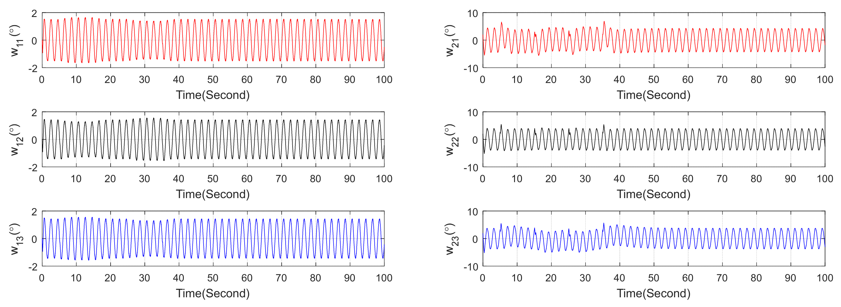
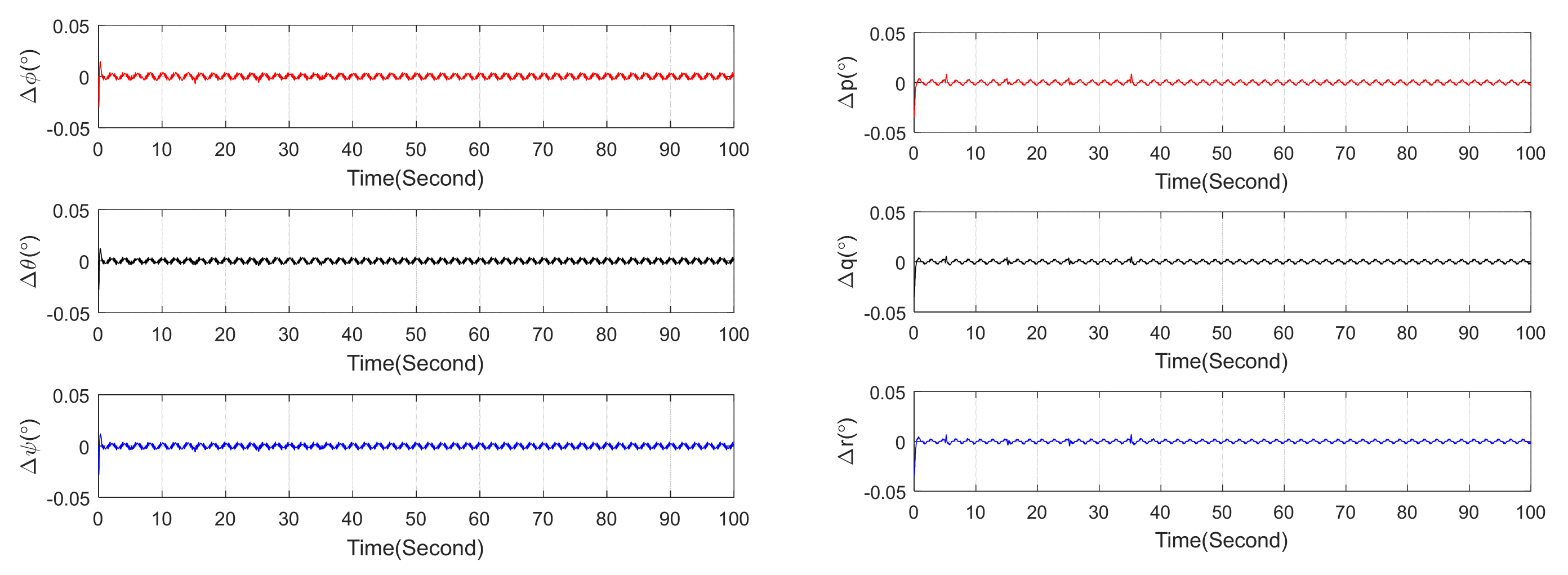
; the attitude angle and angular rate estimation error of the state observer (
Figure 1) and the interference signal are estimated (
Figure 2):
The results indicate that the observation error of the ESO converges, and it accurately estimates the disturbance signals. Therefore, the Backstepping control based on the ESO enhances the control accuracy of the disturbed system.
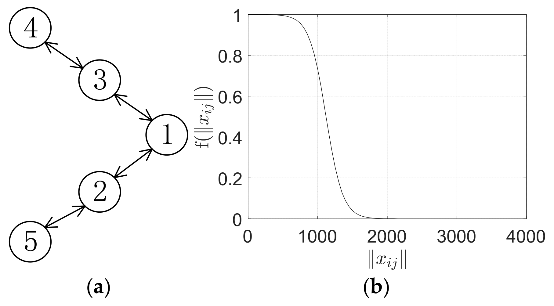
The strong connection diagram
setting is shown in
Figure 3. The time-varying topological function
is shown in
Figure 3, where
. The initial location of the assembly point is shown in
Table 1. In the figure, the numbers 1 to 5 represent formation aircraft.
The assembly reference point is
, and the loose formation constraints are
Tight formation constraints:
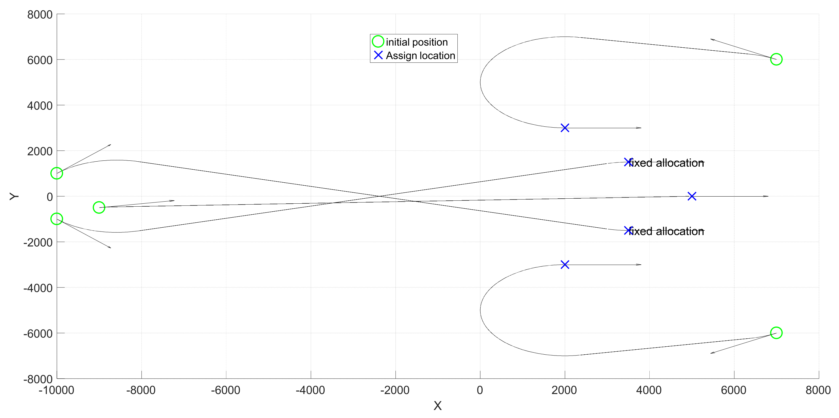
Position allocation is performed for the assembly of five aircraft. The second and third aircraft are assigned fixed positions. The remaining three aircraft are allocated using an improved position allocation strategy based on three-dimensional space mapping, allocation and Dubins curve generation. The results are shown in
Figure 4.
It can be seen that in addition to fixed position allocation, the remaining position allocation can achieve no intersection of Dubins curves, indicating that the improved position allocation based on three-dimensional space mapping is effective. The parameter settings based on the consistency control law are shown in
Table 2.
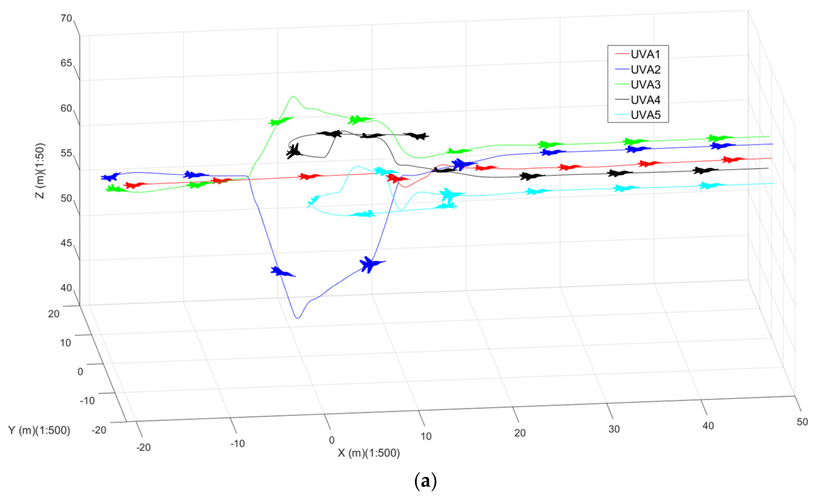
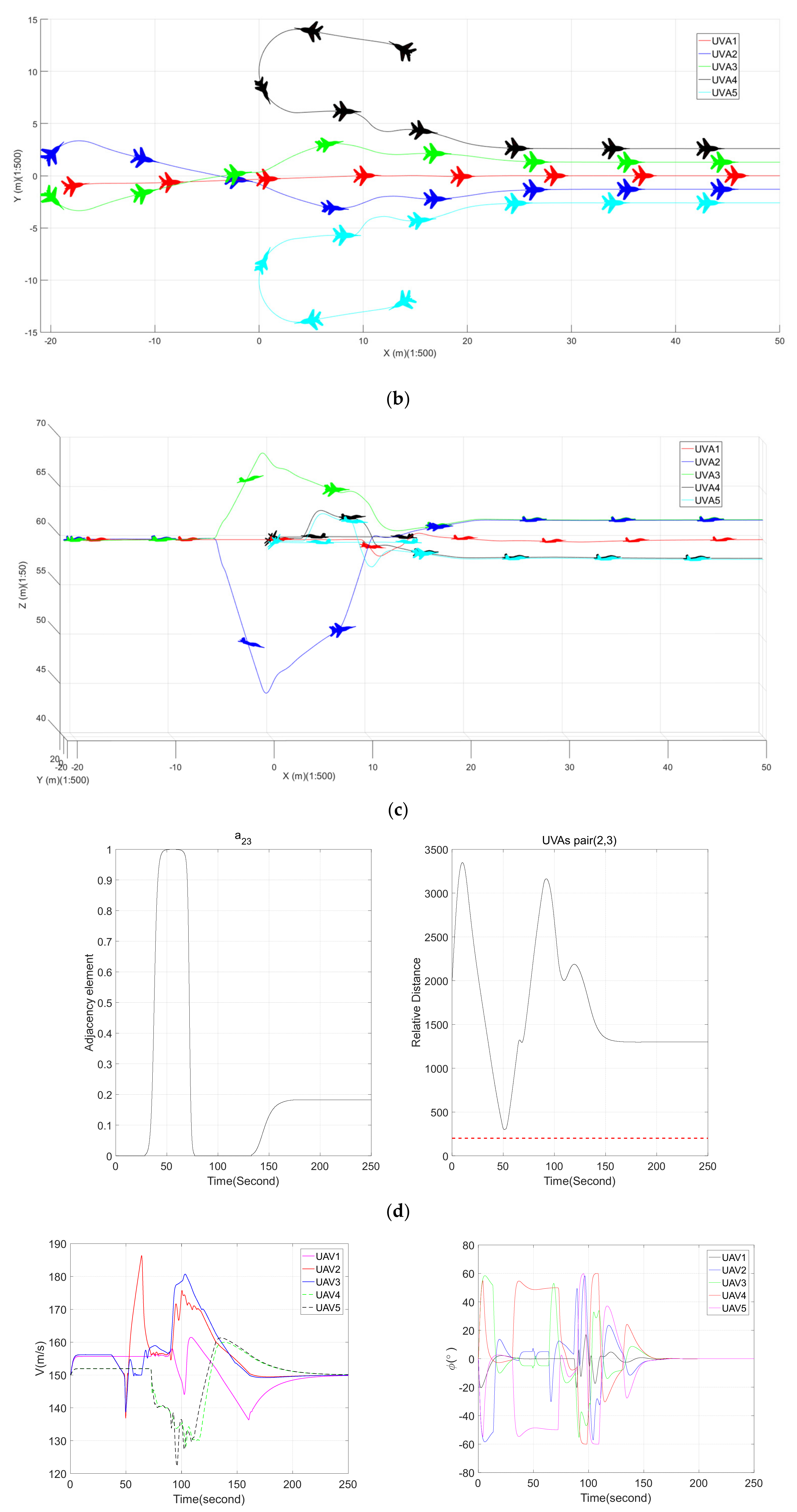
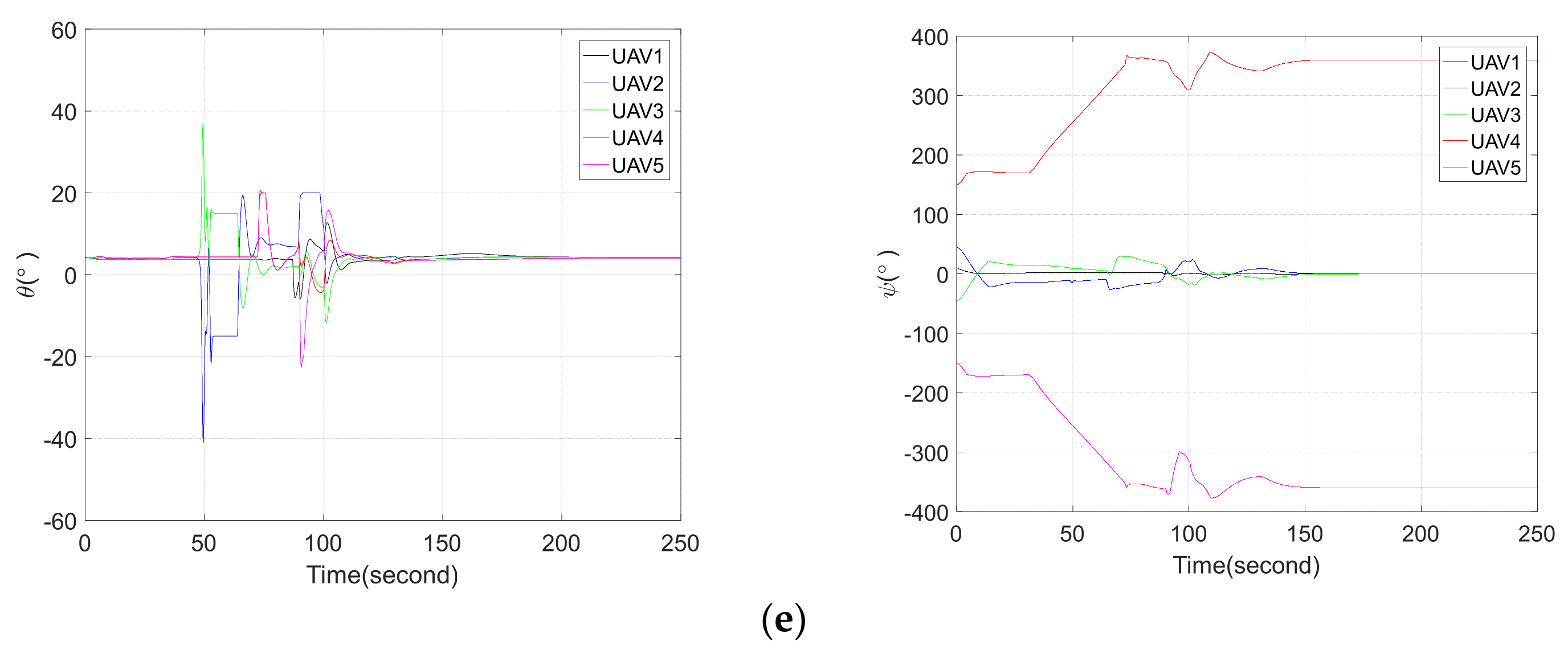
Based on the above simulation settings, the simulation diagram of the assembly process is shown in
Figure 5.
The simulation results show that during the assembly of five aircraft, there is a risk of collision between
and
aircraft and the initial topology of
and
aircraft cannot communicate with each other. Based on the variable-topology design, communication occurs between the
and
aircraft. The topology weights are shown in
Figure 5c, which shows that under the structure of variable topology, the
and
aircraft established communication in time and achieved safe collision avoidance. After completing the collision avoidance, they returned to the assembly route in time, and used the accompanying assembly control law to achieve a sparse formation. Then, the formation transformation based on consistency formed a tight formation, completing the entire assembly process. The state quantity of the entire process changes smoothly and the control is effective.
5. Conclusions
This paper presents the design and investigation of a cooperative assembly control algorithm for multiple aircraft. The design process begins with an inner-loop Backstepping controller based on an extended state observer for aircraft. The observer estimates unknown states and disturbance signals to solve the uncertainty caused by formation changes and aerodynamic interference in formation, which are then compensated for within the control loop, thereby achieving precise aircraft control. Subsequently, for the multi-aircraft assembly task, a three-dimensional position-mapping allocation strategy is devised to generate collision-free assembly paths. To further address potential collision threats during assembly, a variable-topology position allocation algorithm is introduced, ensuring safe operation throughout the process. Moreover, to resolve the issue of asynchronous arrival at assembly points, a set of companion aggregation control laws is developed based on consensus theory. Finally, the stability of the overall system and the effectiveness of the proposed algorithm are validated through simulation experiments, confirming successful cooperative assembly of aircraft formations.
This article mainly designs the control process of formation assembly, tight formation, and formation maintenance of formation aircraft under different topology configurations. In actual flight, due to the influence of airflow interference and environmental factors, more in-depth research and testing are needed, such as considering communication interruption, collision avoidance in formation transformation, fault-tolerant processing of topology structure, and robust control methods to be more in line with the actual environment, and improving the theoretical depth and engineering value of aircraft formation flight control research.