Abstract
Hexaglide parallel manipulators are characterized by high accuracy and dynamic performance, which makes them suitable for industrial high-precision assembly tasks such as placement of electronic THT components on printed circuit boards. In this paper we describe an assembly system that comprises a Hexaglide manipulator with vertical ball screws, moving printed circuit boards relative to stationary THT components. We evaluate the effects of the manufacturing tolerances of machine parts, such as bar length tolerance, ball screw axis position uncertainty, and ball screw axis orientation uncertainty, on Hexaglide end-effector pose accuracy using a geometric simulation study based on stochastic tolerance sampling. In the investigated configuration and under standard industrial tolerances, bar length inaccuracy and axis position uncertainty lead to significant position and rotation deviations for the Hexaglide end-effector in the horizontal plane that need to be compensated for by control algorithms to enable THT assembly using the Hexaglide prototype. The geometric simulation method applied in this paper can be used by designers of Hexaglide machines to study and evaluate different machine configurations.
1. Introduction
Through-hole technology (THT), although responsible for a small proportional of all electronic assemblies, so far remains an irreplaceable manufacturing method in electronics because surface-mount technology (SMT) is limited by the temperature and mechanical stress that the electronic components can endure [1]. As THT components in high-mix, low-volume production can be delivered in small quantities and unstructured forms, many THT assembly tasks in this industry are still manual. At the same time, fierce global competition is a major challenge for the electronics industry in high-wage countries, making automated assembly solutions highly desirable [2]. Robotic assembly of THT components for small- and medium-scale production volumes is a highly demanding task. The robotic manipulators involved need to provide sufficient flexibility to deal with product and process variations. On the other hand, electronic assembly tasks require sub-millimeter absolute accuracies. The application of parallel manipulators in the microelectronics industry was discussed in [3]. High absolute accuracies, low moved masses, and the potential for design miniaturization make this kind of device well-equipped for various manipulation tasks [4]. However, the kinematics of parallel manipulators are not trivial and require substantial application-oriented analysis.
A comprehensive general kinematic analysis of parallel robotic manipulators is provided in [5], including the introduction of the global conditioning index (GCI) and trajectory maps and algorithms for smooth trajectory generation. Hexaglide manipulators represent a special type of parallel manipulator, with six actuated bars of constant length attached to an end-effector (EEF) platform [6]. Honegger et al. [6] derived a dynamic equation for the nonlinear control of a Hexaglide intended for use in high-speed milling applications, thus focusing primarily on the compensation of dynamic effects and not on the kinematic properties of EEF movements. Their work examined a Hexaglide variant with three horizontal linear rails, on which six linear motors were distributed (two motors on each rail). A singularity and kinematic analysis of an analogous horizontal configuration can be found in [7], where three different types of singularity are identified. Ros et al. [8] describe the implementation of a real-time LinuxCNC machine controller for a Hexaglide with six vertical rails. Pott and Hiller [9] provide an approach for estimating the influence of geometric errors on the precision of different parallel kinematic machines (PKMs), including a Linapod, which is another name for a Hexaglide with vertical rails. They report an error amplification factor of between and across a m horizontal workspace section for equally distributed errors in all components.
The state-of-the-art studies discussed above demonstrate that kinematic analysis of parallel manipulators is well-studied in general, particularly in Hexaglides. The majority of the reviewed studies focus on the analysis of milling applications of Hexaglides, where precisely following a planned EEF trajectory is crucial for ensuring high-quality milled products. In the THT assembly of electronic components, precise trajectory following is only required during the search phase if a force sensor-based search procedure is triggered [10]. The required precision is less demanding in THT assembly than in milling applications of comparable dimensions since a m positioning accuracy is sufficient to insert THT components under typical clearances of 0.25–0.7 mm, as defined in the IPC-2222 standard [11] for Level A design producibility. While our previous work [12] already demonstrated a 95.8% robotic THT assembly success rate with different electronic components across different target-hole locations with an imprecise image-based goal input, the influence of various manufacturing tolerances in Hexaglide components on the resulting EEF pose accuracy has not been analyzed yet.
The objective of this paper is to evaluate the pose uncertainty of a particular manufactured Hexaglide prototype against the requirements of THT assembly and compare the relative effect magnitudes of different manufacturing error sources using stochastic geometric simulation. By doing so, we aim to investigate whether the presented stochastic geometric simulation can provide valuable information to guide application-oriented Hexaglide machine design for high-precision manipulation tasks.
The paper is divided into three sections. Section 2 introduces the examined real-world prototype of a Hexaglide manipulator with specific parameters, which is used in subsequent numeric studies. Details on the inverse and forward kinematics calculations required to determine EEF poses for a given set of geometric dimensions are provided. Finally, the method used for the stochastic sampling of manufacturing tolerances to estimate the EEF pose deviations expected in reality is presented. We consider bar length, ball screw axis position, and ball screw axis orientation tolerances, as well as the combination of all three error sources, in our analysis. Section 3 presents statistical data for the expected Hexaglide EEF pose deviations based on stochastic tolerance sampling of the aforementioned manufacturing error sources. This paper is concluded in Section 4, summarizing the findings and putting them into practical context. Recommendations for future research and development are given.
2. Materials and Methods
2.1. Hexaglide Manipulator
In this paper, we analyze a Hexaglide with vertical joint axes (Figure 1a). Despite differing from the horizontal axis configuration presented in [3], the kinematic equations describing the inverse and forward kinematics still hold as there is no specific mathematical constraint on the orientation and location of the axis direction vectors in the equations. Figure 1b demonstrates the built Hexaglide prototype and its application in electronics assembly: the Hexaglide moves a printed circuit board (PCB) relative to a statically held THT component. Table 1 provides the relevant geometric parameters of the Hexaglide prototype that are used in the geometric simulation study. Every bar link has an ideal fixed length of = 236.5 mm.
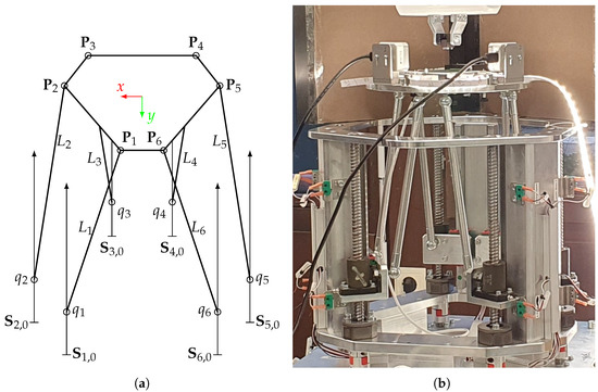
Figure 1.
Studied Hexaglide configuration. (a) Hexaglide kinematic scheme. (b) Hexaglide prototype with ball screws as joint axis actuators. Ball joints are used on both ends of bars.

Table 1.
Geometric parameters of the Hexaglide.
Relevant technical details of the prototype hardware components are given in Table 2. As the following geometric analysis examines purely kinematic relationships between joints and the EEF, a physical reproduction of our system may be implemented using different hardware.
Table 2.
Hexaglide hardware components.
With a known motor step angle, controller position resolution, gearbox reduction ratio, and ball screw lead, the theoretical joint movement resolution equals m. In reality, empirical phenomena like backlash, screw lead errors, and mechanical compliance need to be acknowledged and accounted for. While precisely measuring each of these errors during the operation of a Hexaglide would require costly measurement equipment and therefore prohibit the economical feasibility of the system, their effect can still be estimated using geometric simulation and stochastic tolerance sampling.
2.2. Inverse and Forward Kinematics Calculation
Since the aim of this study is to evaluate the effect of various manufacturing tolerances of the Hexaglide prototype on its EEF pose, a method is required to determine the EEF pose given sampled values of geometric machine parameters.
To this end, based on kinematic equations provided by Palpacelli et al. [3], we implement both the inverse and forward kinematics of the Hexaglide in Python. The inverse kinematic (IK) calculation provides the joint configuration that needs to be used in order to put the EEF into a desired pose . The IKs have no specific parameters other than the previously described Hexaglide geometry, and they require an algebraic equation to be solved in closed form. Forward kinematics (FKs) work in the opposite direction and return the EEF pose that results from putting manipulator joints in a certain configuration . FKs are calculated numerically using a Newton–Raphson algorithm with iteration parameters and , while the numeric constraint tolerance is set to . In a preliminary study of the numerical accuracy of FK solutions, we tested the same area of the workspace as examined in later subsections. The iteration parameters were sufficient to keep the errors between the test joint configurations and joint configurations acquired by applying FKs and then IKs again on , at an order of magnitude of m.
2.3. Stochastic Sampling of Manufacturing Tolerances
The manufacturing-related sources of Hexaglide pose inaccuracy studied in this paper include
- Bar length tolerance;
- Ball screw axis position tolerance;
- Ball screw axis orientation tolerance.
To quantify the sensitivity of Hexaglide EEF poses to various inaccuracies in different regions of its workspace, a random sampling strategy is applied. We sample different error vectors, , from a six-dimensional uniform distribution, , for each test pose and record the maximum achieved position and orientation deviations, :
To keep the computational times of numeric FKs within reasonable limits, the maximum error sensitivity is determined for each point on a 5 mm grid within mm from the home position. For the quantitative bar length error sensitivity analysis, mm is applied. This value corresponds to fine (f) manufacturing tolerances for dimensions of 120 mm mm, as prescribed by the ISO 2768-1 standard [13], considering a Hexaglide bar length of mm. The application of uniformly distributed errors is motivated by providing worst-case estimates without any direction or density preferences.
Analogously, we sample ball screw axis positions times from six three-dimensional uniform distributions centered around each ball screw axis starting point, , within mm limits in each direction. This tolerance value is based on the ISO 2768-1 standard for dimensions from 6 to 30 mm as ball screw positions are referenced as being on the outer edge of the base fixture frame. The corresponding pose deviation is denoted as .
Ball screw axis orientation errors are sampled times within a conical limit from the vertical orientation from a six-dimensional uniform distribution . The angle limit is in accordance with the ISO 2768-1 standard for angle dimensions with a shorter angle side of between 50 and 120 mm. The orientation angle of each ball screw axis projection on the horizontal plane is also varied uniformly within a interval independently for each ball screw axis. The pose deviation caused by axis orientation misalignment is denoted as .
In the final stochastic sampling experiment, we consider all three previously mentioned inaccuracy sources combined to estimate worst-case pose deviations, . The applied tolerance limits remain the same for each error source. The number of sampled geometric configurations is set to per tested pose.
All numeric calculations and graph visualizations were carried out in a Python 3.11 environment on a PC with 16 GB of RAM and an Intel(R) Core(TM) i7-1355U 1.70 GHz processor (Intel, Santa Clara, CA, USA).
3. Results
3.1. EEF Pose Sensitivity to Bar Length Inaccuracies
The results of the stochastic bar length sensitivity analysis described in the Methods and Materials section are presented in Table 3 and Figure 2. The maximum value, , the mean value, , and the sample standard deviation, , are calculated for each of the six error component fields, , with data points in each field.
Table 3.
Statistical properties of maximum absolute EEF pose deviations, , due to bar length inaccuracies, mm, across a mm -section of the Hexaglide workspace sampled on a 5 mm Cartesian grid with samples at each position.
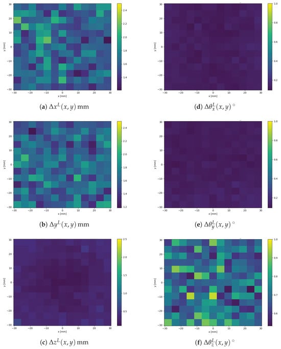
Figure 2.
Maximum absolute components of EEF pose deviations under a bar length uncertainty of mm (sampled from a uniform distribution with samples at each position).
The results shown above suggest that bar length inaccuracies can induce errors in the EEF pose large enough to potentially impair Hexaglide applicability in high-precision assembly if the real dimensions of the Hexaglide machine elements differ from design specifications.
To verify the order of magnitude of the determined mean values, mm in the horizontal plane and mm in the vertical direction, a simplified geometric model of a single bar linkage can be used (Figure 3).
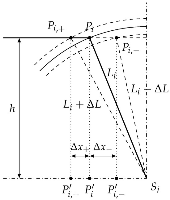
Figure 3.
Geometric model for positional error range verification focusing on a single bar inaccuracy.
With the projected bar length at the EEF home position, p, defined and calculated as
we further calculate the EEF elevation at the home position, h:
Assuming that the other five Hexaglide bars have ideal fixed length L, adding a small inaccuracy, , exclusively to the examined bar length, , only leads to a negligible increase in the elevation of the platform, . We define two new platform connection points, and , for shorter-than-ideal or longer-than-ideal bars. Now, the horizontal EEF deviation magnitudes, , can be determined knowing the bar length error, mm, and the specification bar length, mm:
Note that in reality all six Hexaglide bars are subject to manufacturing inaccuracies, which may either reinforce or diminish the geometric effect explained above. Based on stochastic sampling of these inaccuracies (Table 3), we observe similar magnitudes of and to those predicted by the geometric model.
The sampled rotational errors, and , are approximately 5.6 times smaller than . Together with the prevalence of EEF position deviations, and , we can summarize that the examined Hexaglide configuration displays high sensitivity to bar length errors in the horizontal plane due to the proximity of the Hexaglide bars to the vertical axis. Horizontal movement accuracy is crucial for THT assembly success. The determined horizontal errors of mm are significantly larger than the biggest hole-to-pin tolerance of mm specified by the IPC-2222 standard.
3.2. EEF Pose Sensitivity to Ball Screw Axis Position Inaccuracies
The stochastic sampling experiment data are summarized in Table 4 and represented graphically in Figure A1. The mean deviation magnitudes in all pose elements are approximately twice as low as in the previously presented bar length inaccuracy case. The same relative prevalence of deviations in the horizontal plane, and , can be observed.
Table 4.
Statistical properties of maximum absolute EEF pose deviations, , due to ball screw axis position inaccuracies, mm, across a mm -section of the Hexaglide workspace sampled on a 5 mm Cartesian grid, with samples at each position.
3.3. EEF Pose Sensitivity to Ball Screw Axis Orientation Inaccuracies
The stochastic sampling experimental data for axis orientation sensitivity are summarized in Table 5 and represented graphically in Figure A2.
Table 5.
Statistical properties of maximum absolute EEF pose deviations, , due to ball screw axis orientation inaccuracies, , across a mm -section of the Hexaglide workspace sampled on a 5 mm Cartesian grid, with samples at each position.
Our specific Hexaglide configuration demonstrates significantly lower EEF pose deviations under the tested angular tolerance limit compared to the previously discussed bar length and axis position uncertainties. Nevertheless, horizontal error components still dominate in the EEF pose deviations caused by this type of inaccuracy. Likely due to the circular symmetry of the angular error cone around the vertical axis, the deviation fields , , and shown in Figure A2 display quite pronounced circular symmetries as well. This can be explained by considering that large horizontal movements of the EEF platform, in general, induce large joint displacements along ball screw axes. If an axis is tilted, a joint traveling along it moves away from the ideal vertical line proportionally to the distance traveled, which in turn translates into larger horizontal EEF position errors.
3.4. EEF Pose Sensitivity to Combined Manufacturing Inaccuracies
The last tested case combines bar length, axis position, and axis orientation inaccuracies while keeping their respective tolerance limits used in previous experiments. The stochastic experimental data for combined manufacturing errors are summarized in Table 6 and represented graphically in Figure A3.
Table 6.
Statistical properties of maximum absolute EEF pose deviations, , due to combined manufacturing inaccuracies across a mm -section of the Hexaglide workspace sampled on a 5 mm Cartesian grid, with samples at each position.
The same observations regarding the relative magnitudes of horizontal and vertical EEF pose deviations can be made for the combined manufacturing error case as for separate error sources: manufacturing error transmission is much stronger in the x, y, and directions than in the other three EEF movement directions. Further, no circular symmetry of the combined deviation field is observed as the deviation induced by axis orientation errors is much smaller than those caused by the other error sources.
4. Discussion
This paper demonstrates the application of a simple stochastic simulation method to estimate worst-case pose deviations of a Hexaglide prototype under different manufacturing tolerances. In our case, the Hexaglide manipulator is utilized in the THT assembly of electronic components, which imposes high accuracy requirements. The typical insertion tolerances of THT components are in the sub-millimeter range, making an absolute positioning accuracy of approximately mm desirable. While THT assembly is a very specific application, its high precision requirements make it an interesting case study for other industries.
A Hexaglide parallel manipulator is a complex machine with multiple stationary and moving parts. The accuracy of the EEF platform’s movement is influenced by the mechanical properties of the machine parts. Beginning from the base of a Hexaglide, inaccuracies can occur in the placement of the motors in the base frame. Further inaccuracies can stem from the transmission and coupling between the motor and the vertical ball screw, which will typically result in differences between the commanded and real joint configurations. Depending on the quality of bearings and their real positions within the machine, the real ball screw axis can also have an angle slightly different to the ideal geometric model used in kinematic calculations for EEF movement commands. Continuing the analysis, the ball joints on both ends of bars can have tolerances between their rotating spherical parts. The real length of Hexaglide bars is also subject to manufacturing inaccuracies. All these listed inaccuracies are largely independent from each other and can potentially be different for all six legs.
In this study, the aforementioned error sources are modeled by three uniformly distributed errors: bar length errors, ball screw axis position errors, and ball screw axis orientation errors. Each of the error magnitudes is assumed to be within the fine (f) tolerance limits prescribed by the ISO 2768-1 General Tolerance Standard.
The results of the stochastic simulation study presented in Section 3 demonstrate the high importance of such analysis to inform further developments in Hexaglide control algorithms. For instance, bar length inaccuracies of mm can, on average, lead to ≈1.6 mm horizontal EEF position deviations across the workspace, and in the worst case out of a total of 16,900 sampled bar length configurations, these deviations can even reach up to ≈2 mm. Combined with the tested axis position and orientation errors, these worst-case values increase even further, up to ≈1.9 mm on average and ≈2.5 mm in the extreme case. Compensating such large deviations requires a calibration technique that estimates geometric machine parameters based on multiple precise pose measurements before productive Hexaglide operation or a sensor-based control approach during its productive operation.
Another finding of this study is that the horizontal translations and the rotation around the vertical axis (yaw) of the EEF platform of the Hexaglide are much more sensitive to all three tested error types than vertical translation or roll and pitch angles. It cannot be stated that the errors in the joints and links of this particular Hexaglide are balanced out by each other; rather, we can only claim that they are not significantly amplified in the vertical direction relative to the EEF platform. On the other hand, the position and length inaccuracies of Hexaglide components in the investigated configuration are, in the worst cases, amplified by 8–10 times when we analyze horizontal translations or yaw rotations. The mechanism behind this amplification is explained based on the simplified geometric model shown in Figure 3.
The conclusions of this study have important implications for Hexaglide manipulators used in fine-grained assembly requiring sub-millimeter absolute accuracies. A general recommendation can be given to design Hexaglide manipulators in such a way that the EEF platform and the joint bars are kept closer to the horizontal plane, as this reduces the error amplification factor in the horizontal direction, which is relevant for flat assembly operations like THT. The applied approach of stochastic error sensitivity analysis can be used to evaluate different Hexaglide configurations during the design phase.
Comprehensive modeling of the influence of motor backlash, the mechanical deformation of components, or temperature on geometric parameters is not presented in this paper but could be further investigated in different use cases requiring even higher accuracies than THT electronic assembly. With a stable image-based control method, which we aim to develop in future work, the inaccuracies in Hexaglide EEF poses should be iteratively reduced to meet the requirements of THT assembly. Henceforth, the Hexaglide could also be significantly miniaturized, bringing inherent benefits like the scalable manufacturing of its identical parts, high stiffness, and lower moved masses.
Author Contributions
Conceptualization, M.P.; methodology, M.P.; software, M.P. and Y.M.; formal analysis, M.P.; resources, J.D.; writing—original draft preparation, M.P.; writing—review and editing, J.D. and Y.M.; visualization, M.P.; supervision, J.D.; funding acquisition, J.D. All authors have read and agreed to the published version of the manuscript.
Funding
This research was funded by the German Federal Ministry for Economic Affairs and Climate Action (BMWK) under grant number KK5072203WO0.
Institutional Review Board Statement
Not applicable.
Informed Consent Statement
Not applicable.
Data Availability Statement
We provide Jupyter Notebooks with Python code for the reproducibility of our results and easy adaptation to other Hexaglide configurations: https://github.com/institute-of-production-systems/hexaglide-movement-quality-analysis (accessed on 5 September 2025).
Acknowledgments
We kindly thank Günther Fickler and Pascal Messmer from SFA Mechanische Fertigung/Sondermaschinenbau Gmbh & Co. KG for their technical support and providing us access to the Hexaglide prototype.
Conflicts of Interest
Author Y.M. was employed by the company SFA Mechanische Fertigung/Sondermaschinenbau GmbH & Co. KG. The remaining authors declare that the research was conducted in the absence of any commercial or financial relationships that could be construed as a potential conflict of interest. The funders had no role in the design of the study; in the collection, analyses, or interpretation of data; in the writing of the manuscript; or in the decision to publish the results.
Abbreviations
The following abbreviations are used in this manuscript:
| THT | Through-hole technology |
| SMT | Surface-mount technology |
| GCI | Global conditioning index |
| EEF | End-effector |
| PKM | Parallel kinematic machines |
| IK | Inverse kinematics |
| FK | Forward kinematics |
| PTP | Point-to-point |
| PCB | Printed circuit board |
Appendix A
Appendix A.1

Figure A1.
Maximum absolute components of EEF pose deviations under ball screw axis position uncertainty mm ( samples at each position).
Appendix A.2

Figure A2.
Maximum absolute components of EEF pose deviations under ball screw axis orientation uncertainty (sampled from a uniform distribution with samples at each position).
Appendix A.3

Figure A3.
Maximum absolute components of EEF pose deviations under combined uncertainty (sampled from a uniform distribution with samples at each position).
References
- Williams, T. The Circuit Designer’s Companion, 2nd ed.; Elsevier: Oxford, UK, 2005; pp. 58–59. [Google Scholar]
- Feldmann, K.; Reinhardt, A.; Pfeffer, M. Einleitung. In Montage in der Leistungselektronik für Globale Märkte; Feldmann, K., Ed.; Springer: Berlin/Heidelberg, Germany, 2009; pp. 1–2. [Google Scholar]
- Palpacelli, M.-C.; Carbonari, L.; Palmieri, G.; D’Anca, F.; Landini, E.; Giorgi, G. Functional Design of a 6-DOF Platform for Micro-Positioning. Robotics 2020, 9, 99. [Google Scholar] [CrossRef]
- Hesse, S. Grundlagen der Handhabungstechnik, 5th ed.; Hanser: Munich, Germany, 2020; pp. 455–458. [Google Scholar]
- Gosselin, C. Kinematic Analysis, Optimization and Programming of Parallel Robotic Manipulators. Ph.D. Thesis, McGill University, Montréal, QC, Canada, 1988. [Google Scholar]
- Honegger, M.; Codourey, A.; Burdet, E. Adaptive control of the Hexaglide, a 6 DOF parallel manipulator. In Proceedings of the International Conference on Robotics and Automation, Albuquerque, NM, USA, 25 April 1997. [Google Scholar]
- Abtahi, M.; Pendar, H.; Alasty, A.; Vossoughi, G. Kinematics and singularity analysis of the Hexaglide parallel robot. In Proceedings of the 2008 ASME International Mechanical Engineering Congress & Exposition, Boston, MA, USA, 31 October–6 November 2008. [Google Scholar]
- Ros, J.; Yoldi, R.; Plaza, A.; Iriarte, X. Real-Time Hardware-in-the-Loop Simulation of a Hexaglide Type Parallel Manipulator on a Real Machine Controller. In New Trends in Mechanism and Machine Science; Viadero, F., Ceccarelli, M., Eds.; Springer Science+Business Media: Dordrecht, The Netherlands, 2013; pp. 587–597. [Google Scholar] [CrossRef]
- Pott, A.; Hiller, M. Kinematic Modeling, Linearization and First-Order Error Analysis. In Parallel Manipulators, Towards New Applications; Wu, H., Ed.; IN TECH d.o.o.: Rijeka, Croatia, 2008. [Google Scholar] [CrossRef]
- Polikarpov, M.; Mehmood, Y.; Boiar, D.; Schulte, L.; Deuse, J. A Cost-Efficient Robotic Through-Hole Assembly System for Dual-Pin Component Insertion. In Proceedings of the 2023 11th International Conference on Control, Mechatronics and Automation (ICCMA), Grimstad, Norway, 1–3 November 2023. [Google Scholar] [CrossRef]
- IPC-2222; Sectional Design Standard for Rigid Organic Printed Boards. Institute of Printed Circuits: Northbrook, IL, USA, 1998.
- Polikarpov, M.; Mehmood, Y.; Boiar, D.; Deuse, J. Cost-efficient sensor assisted robotic assembly—Assembly manipulator for PCB assembly. Werkstattstech. Online 2024, 114, 9. [Google Scholar] [CrossRef]
- ISO 2768-1; General tolerances—Part 1: Tolerances for Linear and Angular Dimensions Without Individual Tolerance Indications. International Organization for Standarization: Geneva, Switzerland, 1989.
Disclaimer/Publisher’s Note: The statements, opinions and data contained in all publications are solely those of the individual author(s) and contributor(s) and not of MDPI and/or the editor(s). MDPI and/or the editor(s) disclaim responsibility for any injury to people or property resulting from any ideas, methods, instructions or products referred to in the content. |
© 2025 by the authors. Licensee MDPI, Basel, Switzerland. This article is an open access article distributed under the terms and conditions of the Creative Commons Attribution (CC BY) license (https://creativecommons.org/licenses/by/4.0/).