Abstract
Wave-based control (WBC) offers a relatively novel approach to the challenge of controlling flexible mechanisms by treating the interaction between actuator and system as the launch and absorption of mechanical waves. WBC is a robust approach but has been unexplored in active suspension systems to date. This study adapts WBC to a quarter-car suspension model. Having embedded an actuator as the active element of a car suspension, a novel but simple ‘force impedance’ adaptation of WBC is introduced and implemented for effective vibration control. Testing with various input signals (pulse, sinusoidal, and random profile) highlights the active system’s significant ride comfort and rapid vibration suppression with zero steady-state error. Compared to two other models—one employing an ideal skyhook strategy and the other a passive suspension—the active system utilizing WBC outperforms across many criteria. The active controller achieves over 38% superior ride comfort compared to the skyhook model for a pulse road input. This is accomplished while adhering to WBC principles: relying solely on actuator-interface measurements, simplicity, cost-effectiveness, with no need for detailed system models, extensive sensors, or deep system knowledge.
1. Introduction
Active suspension systems in road vehicles have seen significant advancements over the years, aimed at improving ride comfort, handling performance, and stability. They utilize actuators to generate adjustable forces between the vehicle’s sprung and unsprung masses, enhancing both ride comfort and handling. Ride comfort pertains to the vehicle’s ability to reduce the acceleration of mechanical vibrations felt by passengers, caused by uneven road surfaces [1]. These suspension systems incorporate actuators that modulate forces between the sprung and unsprung masses, playing a pivotal role in improving ride comfort in future vehicle designs.
Numerous theoretical studies have demonstrated that active or semi-active suspension systems outperform passive suspension systems in various performance metrics [2,3,4]. The performance of the actuators used in active suspension systems is handled by different controllers, which have been extensively researched. The current study explores the effectiveness of a wave-based controller on dampening the vibrations of these systems, which has never been studied to date.
Several studies proposed in recent years have focused on developing and refining control strategies to achieve faster response times [5], better vibration suppression [6], improved robustness [7], or efficient energy use [8]. The improvements in suspension behavior have been made through a range of control approaches. For example, adaptive controllers have been developed that automatically adjust suspension parameters in real-time based on changing road conditions and vehicle dynamics. Mousavi et al. [9] have integrated a model reference adaptive control (MRAC) to provide real-time adaptation for different road profiles. Despite MRAC’s ability to handle parameter variations, adaptive controllers often face challenges in terms of computational complexity and sensitivity to model inaccuracies, which can affect their performance under extreme conditions or sudden changes. The high computational demand and dependence on accurate modeling can limit the real-time performance of adaptive controllers, especially in vehicles with limited onboard processing power. Lai et al. [10] explored a two-layered control framework for active suspension systems using electromagnetic actuators, integrating LQR and a Field-Oriented Control (FOC). The system enhances vibration isolation; however, again, the reliance on precise actuator calibration and computational demand can limit real-time application efficiency. Robust control strategies, including sliding mode control (SMC) and H-infinity (H∞) control, have also been utilized to maintain consistent performance despite system uncertainties and external disturbances. In studies by Kim and Lee [11,12], a nonlinear controller based on SMC was developed for an air suspension system. This controller manages vehicle sprung mass height (height control) and regulates the roll and pitch angles of the vehicle body (leveling control). By addressing nonlinearities and uncertainties, the system achieves improved tracking accuracy and robustness. Additionally, a sliding mode observer is implemented to estimate the pressure in the four air springs. As for the H∞ method, Yu et al. [13] introduced a multi-objective PID controller as the outer-loop controller to stabilize the vehicle chassis at a desired attitude, with an H∞ controller serving as the inner-loop controller to minimize disturbances from road unevenness, ensuring optimal ride comfort and road holding performance. To achieve zero tracking error in the chassis attitude reference signals, free integrators were added to effectively connect the outer-loop PID and the inner-loop H∞ controllers. Although numerical simulations demonstrated favorable results, a performance trade-off was observed when compared to using a dedicated chassis attitude controller or vibration attenuation controller alone. Overall, while both approaches provide a stable response even with modeling errors and external noise, they often involve complex mathematical formulations and can be overly conservative. This conservatism may result in suboptimal performance and reduced ride comfort.
Recently, traditional control methodologies have been integrated with intelligent control strategies, such as fuzzy logic [14], neural networks [15], genetic algorithms [16], and other advanced data-driven control techniques. This fusion enables more adaptive and robust control systems that could deal with different road conditions and driving scenarios more effectively. These systems can learn and adapt to complex patterns, providing efficient suspension control without requiring a detailed physical model of the system. Despite their promising results, intelligent controllers often lack transparency and are computationally expensive. Additionally, the need for extensive training data and the potential for overfitting remain considerable concerns.
The current study investigates the application of wave-based control (WBC) as the main controller in an active suspension system. This technique offers a relatively novel and simple approach to the challenge of controlling flexible systems by treating the interaction between the actuator and the system as the launch and absorption of mechanical “waves” or propagating disturbances. This control technique is commonly applied to systems modeled using lumped parameters, where the total system mass is distributed among discrete, rigid masses connected by flexible, massless springs [17,18]. Known for its model-independent formulation and inherent robustness, wave-based control (WBC) remains largely unexplored in the context of active suspension systems. Nevertheless, it has been extensively studied and successfully applied across a variety of challenging domains. For instance, WBC has been experimentally validated on a highly flexible and lightweight robotic arm driven using a DC motor, which repositions a tip mass across a nearly frictionless air table within a horizontal plane [19]. It has also proven effective in the control of cable-driven manipulators and large-scale flexible cable structures operating over wide workspaces—systems that are traditionally difficult to manage due to their inherent compliance and low damping [20,21,22], including one study with experimental validation [20]. Furthermore, WBC has been employed for motion and slewing control in satellite models with flexible appendages [23], and has demonstrated practical success in various crane systems such as overhead gantry and luffing boom cranes [24,25], including a notable experimentally validated study on the wave-based control of cranes with complex loads [26].
Wave-based control provides a strategic approach with several advantages over classic control methods. By leveraging the inherent properties of flexible systems, WBC does not rely on a detailed system model, making it robust to variations in system parameters and actuator limitations. This flexibility allows it to be effectively applied across a wide range of systems, enabling rapid and nearly vibration-free repositioning of both the structure and any attached load (tip mass). Instead of viewing system flexibility as a challenge, WBC integrates it naturally into the control process. The core concept involves treating actuator movements as waves that propagate through the flexible system, while also actively absorbing any returning waves. The term “wave” encompasses not only oscillatory behavior but also changes in the steady-state (or DC) component that remains once the wave has passed. This approach inherently handles both transient and steady-state behavior, as well as the interplay between flexible and rigid body motions, without the need for artificial separation or concerns about cross-coupling. Consequently, WBC achieves efficient and unified control through a single, cohesive motion strategy.
Classical controllers, including fractional order variations, often fail to address the peculiar dynamic characteristics and non-minimum phase behavior typical of oscillatory systems. This limitation is particularly pronounced due to time delays between actuator movement and the corresponding tip motion. In contrast, WBC addresses these challenges by conducting rest-to-rest maneuvers that identify, measure, and leverage the inherent propagation time delays of flexible systems. Remarkably, WBC accomplishes this without needing a comprehensive system model and achieves near-theoretical minimum time, comparable to time-optimal control [27], in a robust and versatile manner.
This study applies WBC to a lumped mass–spring quarter-car suspension model. By incorporating an actuator model into the quarter-suspension system, the ‘force impedance’ variant of WBC [24] is adapted for its simplicity in implementation and effectiveness in vibration control. While this study demonstrates the WBC effectiveness, it does not aim to present WBC as superior to all modern strategies for active vibration control, such as Model Predictive Control (MPC), adaptive control, AI-based controllers, etc. [28,29]. Instead, the value of WBC lies in its ability to deliver competitive performance using minimal sensing, no requirement for full-state estimation, and robust handling of wave propagation in the flexible suspension system, presenting its response to different road inputs. These features also make WBC especially attractive in scenarios where implementing dense sensor–actuator networks is impractical, such as in lightweight robotic arms or spacecraft structures.
The structure of the paper is as follows: Section 2 introduces and discusses the new adaptation of WBC for controlling the suspension system. Section 3 provides a detailed description of the quarter-car active suspension model. Section 4 presents and analyses the performance results of the adapted approach when applied to the modelled suspension system under various road inputs. Finally, Section 5 summarizes the findings and offers concluding remarks.
2. Adaptation Concept of WBC Approach
The original concept and principles of the WBC approach have been thoroughly examined in past studies across various applications [17,18,19,20,21,22]. In essence, WBC relies on the interaction between the actuator and the flexible system by “launching” and “absorbing” mechanical waves (propagating disturbances). The initial innovation was to integrate position control with active vibration damping within a single actuator, achieved by simultaneously launching and absorbing motion in a controlled manner with no need for a feedback loop. The returning or “absorbing” wave, denoted as b(t), can be defined and measured through various methods. Although these methods yield somewhat different control schemes, they generally produce comparable control responses, making the choice largely one of convenience. In this study, we employ one of these methods, the so-called “force impedance” method, which, unlike others, does not use a wave transfer function. This method has been adapted for implementation in multiple contexts [23,24,25] and has now been customized specifically for a suspension system, as discussed here.
The control objective in the standard classic WBC concept illustrated in Figure 1 is defined by the position reference input r(t), which specifies the desired target displacement for the system. For instance, if r(t) = 1 m, the actuator—and, consequently, the connected chain of lumped masses—will execute a coordinated motion to bring the entire system, including the tip, to the 1 m position, achieving a smooth rest-to-rest transition. This motion is initiated by the actuator’s motion input, c(t), which comprises a ‘launch’ displacement a(t) of half the reference displacement, ao = 0.5*Ref, (or a(t) = 0.5*r(t)) and a measured ‘return’ displacement, b(t), bringing about active vibration damping, determined by the following:
where x(t) is the resulting actuator’s actual position and f(t) is the force measured at the interface between the actuator and the flexible system. These two variables are the only measurements needed in the classic WBC implementation to determine the returning wave, b(t), which enables the controller to combine position control and active vibration damping seamlessly in a single actuator motion. Hence, the actuator’s motion is given by the following:
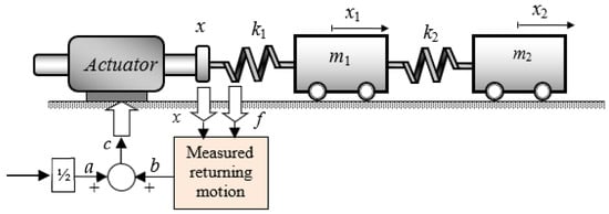
Figure 1.
Wave-based, single-actuator control of a 2-DOF mass–spring system.
It should be noted that within the WBC framework, the actuator is assumed to incorporate its own position sub-controller, whether open-loop (e.g., a stepper motor) or closed-loop with position feedback from the actuator itself (e.g., a servo motor). The internal dynamics of the actuator and its sub-controller are not of direct concern in WBC, provided that (a) it has sufficient power to drive the flexible system, (b) it can achieve zero steady-state error, and (c) its bandwidth encompasses the highest natural frequency to be controlled. These requirements are modest, readily achievable in practice, and considered standard in typical engineering systems. This study has considered a typical electro-hydraulic servo actuator.
In addition, Z in Equation (1) is the so-called impedance, where the steady-state response holds regardless of its value. This parameter has been discussed extensively in past studies, which have shown that the choice of impedance values is not critical [25].
To illustrate the adaptation of the traveling wave concept, consider a representative example: a vertically oriented rectilinear mass–spring system controlled by a single actuator, as shown in Figure 2.
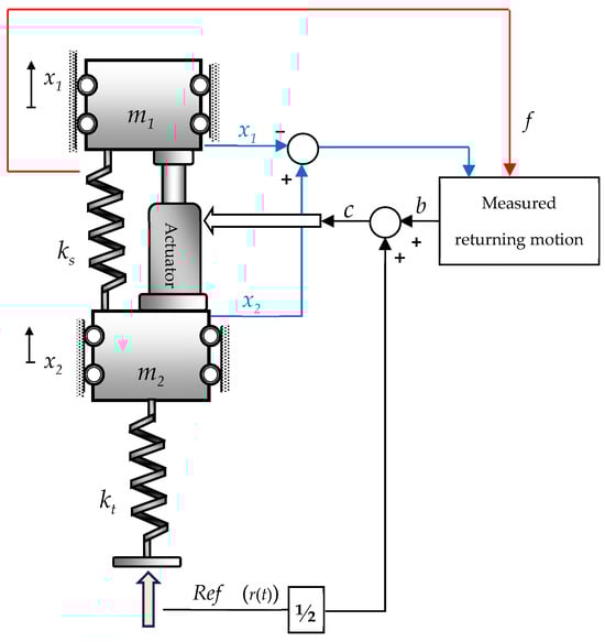
Figure 2.
The basic concept for the wave-based controller evolved for the car suspension system.
A directly controlled actuator regulates the motion of a suspended flexible system constrained to move in the vertical direction. When subjected to uneven road input (Ref), the unsprung mass m2 triggers the actuator’s motion input, c(t). In the suspension system illustrated in Figure 2, the actuator input c represents the displacement applied to the actuator and the connected system. However, unlike the sprung mass (m1) in Figure 1, which is expected to move toward the target Ref, the ideal behavior for m1 in Figure 2 is to remain stationary at a zero-displacement level.
To achieve this, the adapted WBC approach in Figure 2 computes the displacement difference (x2 − x1) rather than measuring only x as in Figure 1. This allows the returning wave to act as a vibration sink by generating an immediate actuator force in the opposite direction of the road input force. This responsive action minimizes the movement of the sprung mass (x1), bringing it closer to zero, effectively setting the returning motion as
In suspension systems, the primary objective is to control vibration rather than a combination of vibration and position, aiming to minimize the vertical acceleration of the sprung mass (m1). Consequently, the first term in Equation (2), 0.5r(t), is omitted. This simplifies the control input to c(t) = b(t), which is ultimately designed to pull m1 toward m2 in response to an upward road input, as illustrated in Figure 2. Furthermore, since the ideal behavior is for the net displacement of the sprung mass (x1) to remain at zero (x1 = 0), it was inferred that the returning wave b(t), defined by Equation (3), can be further simplified. The coefficient 0.5 and the term 0.5 are removed, resulting in a more streamlined expression for b(t). This adaptation has been incorporated into the development of the WBC-assisted quarter-car model, which is detailed in the next section.
3. Quarter-Car Model of Active Suspension
3.1. Implementing Adapted WBC on the Suspension Model
To evaluate the performance of the newly adapted controller designed for active suspension systems, a standard 2-DoF quarter-car model was developed. As shown in Figure 3, the active suspension model consists of a spring (K), a shock absorber (C), and an actuator (P). Also, Kt represents tire stiffness. In this model, ms and mu denote the car’s sprung mass (comprising the chassis, body, and passengers) and unsprung mass, respectively. The vertical displacement of the road input is represented by Yr, while Yu and Ys denote the vertical displacements of mu and ms, respectively. The actuator (P), which exerts the control force fa, serves as the active suspension actuator where the wave-based controller is implemented. Its purpose is to regulate the vertical displacement and minimize the vertical acceleration of the sprung mass (ms). If the actuator P is removed, the active suspension system reverts to a passive system. The signal composition and wave-based formulation underlying the suspension-specific implementation in Figure 3 are illustrated in more detail in Figure 2, where the actuator command c(t) is derived from the combination of the return wave b(t) and half of the reference input r(t) reflecting the road profile.
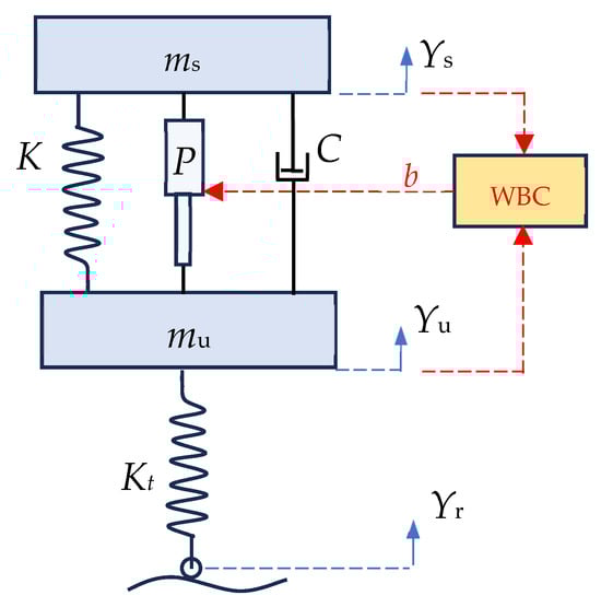
Figure 3.
A quarter car active suspension model with actuator P operated using WBC.
As per Newton’s law, the differential dynamics for the sprung mass and the unsprung mass are respectively presented as follows:
These two highly coupled equations of motion capture the full system dynamics. These equations can be integrated numerically from given initial conditions to describe the time evolution of the system. The road surface profile is considered as input, indicated by in Equation (5). In the first numerical iteration of solving this set of equations, the actuator force is set as ; however, in the next iterations, where the actuator operates in responding to the road input , the required actuator force is calculated by rearranging Equation (4) to the following:
The force exerted by the actuator to minimize vibrations, as defined by Equation (6), is effectively equal in magnitude to the force measured from the passive suspension system but acts in the opposite direction. In other words, the force is utilized in the adaptation formula of the WBC approach for the suspension system. Consequently, the returning wave b, as depicted in Figure 3, is calculated as follows:
where substituting (6) in (7) yields
As discussed in the previous section, the objective of a car suspension controller is to stabilize the vertical position of the sprung mass on uneven roads. This contrasts with conventional WBC applications, which aim to simultaneously manage vibration and position control. To align with this objective, the displacement-related terms in Equations (2) and (3) have been excluded, simplifying the required actuator motion c(t) in Equation (2) to the following:
By measuring the vertical displacements of the sprung () and unsprung () masses, the WBC approach calculates the force generated within the flexible system. This preserves one of WBC’s key advantages, which is the requirement for only minimal measurements taken at the actuator-flexible system interface.
It should be noted that this control configuration is independent of the force impedance Z; its value is not critical to the overall control scheme. This has been systematically investigated in our earlier work [25], which demonstrated that system performance remains robust across a broad range of Z values, provided they fall within physically admissible limits. Therefore, in this study, a nominal value of Z was selected to focus on the primary objective of demonstrating WBC’s feasibility for suspension systems. The force impedance was set as . While variations in Z introduce minor changes to the transient response, they provide an opportunity to fine-tune the system’s performance. For instance, Z can be adjusted to optimize specific transient characteristics, such as rise time, overshoot, or settling time, depending on the application’s requirements. However, this optimization often comes with trade-offs, as enhancing one performance measure may lead to slight compromises in others.
3.2. Skyhook Suspension Model for Benchmarking
To evaluate the performance of this new WBC adaptation in dealing with road obstacles and unevenness, the response of the quarter-car model will be compared against both a passive suspension system and a suspension with an ideal skyhook system. The skyhook model is a theoretical control concept that modifies the damping force dynamically to counteract body oscillations caused by road irregularities. As displayed in Figure 4, it is based on the idea of an imaginary “skyhook” that provides a fixed reference point in space. The system aims to reduce vertical body motion by simulating the effect of attaching the vehicle body to the fixed skyhook via a damper. This control strategy is applicable for both a semi-active system as well as an active system to reduce the resonant peak of the sprung mass significantly and thus achieves a good ride quality [2].
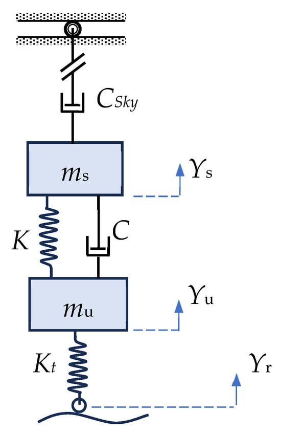
Figure 4.
Schematic illustration of an ideal skyhook suspension model.
Achieving a true skyhook model in practical applications is infeasible due to the absence of a fixed point in space to anchor the damper. However, the concept is approximated in real systems using sensors and actuators, which modulate the damper force based on the relative velocities between the vehicle body and the wheel. In recent advancements in vibration control, such as physics-driven strategies for railway suspensions, the conventional skyhook model integrated with groundhook elements, has been used as a baseline for performance comparison, highlighting its continued relevance and effectiveness as a benchmark for evaluating emerging control technologies [30]. Another recent study also adopted skyhook damping as a foundational control method to examine phase deviation effects and demonstrated that integrating structure-based compensation significantly improves suspension performance in semi-active inertial systems across comfort, deflection, and road-friendliness criteria [31].
In the current study, an ideal skyhook model, as shown in Figure 4, is utilized to achieve optimal performance for benchmarking against the adapted WBC model. This idealized approach eliminates the constraints associated with a modulated real skyhook system, enabling a direct comparison with the highest achievable performance of the skyhook model. By doing so, the study ensures that the evaluation of the WBC model is conducted against the most effective implementation of the skyhook concept as presented and discussed in the next section.
4. Modelling Results
This study evaluated the performance of WBC in vibration control, comparing it to two other suspension systems: a passive suspension model (where the actuator P is removed from Figure 3) and a suspension system incorporating an ideal skyhook model, as shown in Figure 4. The skyhook model uses a damping coefficient of CSky = 5000 Ns/m, which significantly enhances the vibration suppression rate in the sprung mass. The three models were subjected to common road input profiles (Yr), including pulse, sinusoidal, smooth ramp–puddle-like, and randomly generated profiles, to facilitate a comparative analysis. The following parameters for the models, as shown in Figure 3, were selected to approximate real-world values for a passenger car and its suspension system: mu = 20 kg, ms = 1000 kg, Kt = 50,000 N/m, C = 5000 Ns/m, and K = 16,000 N/m.
The first test involved a pulse input with an amplitude of 0.05 m, lasting 0.5 s, and occurring at t = 2 s. The system’s response, in terms of the vertical displacement of the sprung mass (mu), is shown in Figure 5. While the rise time to reach approximately half of the input’s magnitude is similar across all three suspension models, the WBC-assisted model exhibits a lower overshoot during the initial bounce. This overshoot typically represents the maximum vertical displacement experienced by the sprung mass. The reduced overshoot in the WBC model demonstrates its superior performance in effectively managing the initial road shock in the vertical direction.
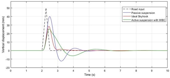
Figure 5.
Dynamic response of the sprung mass (Ys) to a pulse-shaped road input, demonstrating the transient behavior and stabilization of the sprung mass using passive, ideal skyhook, and WBC-assisted active suspension systems.
Another observation from the pulse response is that the suspension model equipped with the ideal skyhook damper exhibits a relatively better settling time compared to the system using WBC. However, the key criterion for ride comfort is the vertical acceleration experienced by the passenger (sprung mass), which was measured during the pulse input and is shown in Figure 6. As depicted in this graph, the passive suspension model results in the largest initial overshoot and the longest settling time, as expected. In contrast, the skyhook model immediately reduces the initial peak after the pulse input; however, it experiences a significant second peak in the vertical acceleration of the sprung mass approximately one second later. On the other hand, the active suspension model with WBC achieves the lowest acceleration amplitudes during both the first and second overshoots, even without the use of additional damping or extensive sensors, which highlights the effectiveness of WBC in minimizing vertical acceleration and improving ride comfort.
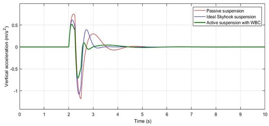
Figure 6.
System response: vertical acceleration of sprung mass () when subjected to a pulse-shaped road input.
Thus, WBC responds with a smaller initial jump and provides a higher level of ride comfort, despite being slightly slower than the skyhook model when the road input changes suddenly, such as when the vehicle hits a road shoulder. By summing the absolute values of the first three peaks in each model’s acceleration response shown in Figure 6, the WBC yields a total of approximately 1.3 m/s2, while the skyhook and passive models result in about 2.1 m/s2 and 2.25 m/s2, respectively. This indicates that the WBC-assisted suspension delivers more than 38% better ride comfort over the first second following a sudden road disturbance compared to the ideal skyhook suspension system.
As the second test, the developed suspension model was operated under an uneven, periodically varying road surface. Figure 7 illustrates the performance of the WBC in tracking the suspension system’s displacement under sinusoidal road input conditions, which simulate the wavy profile of a typical road surface. The sinusoidal signal, used as the road input, induces vertical movement of the vehicle mass at a frequency of 5 rad/s (0.796 Hz) with an amplitude of 50 mm.
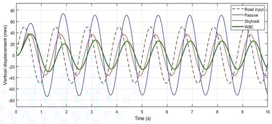
Figure 7.
Response of the sprung mass (Ys) to sinusoidal road input, which shows the oscillatory behavior and vertical displacement of the sprung mass, comparing passive, ideal skyhook, and WBC-assisted active suspension systems.
Due to the relatively high frequency of the road input, a phase difference and delay emerge in the displacement tracking across all three models. However, the suspension model with WBC effectively suppresses the vibration of the sprung mass under steady-state conditions, reducing the amplitude from 40 mm to approximately 25 mm, whereas the skyhook model achieves a reduction to 36 mm. This demonstrates that WBC outperforms the skyhook model in handling sinusoidal road inputs.
Interestingly, the WBC’s performance with sinusoidal inputs exceeds its effectiveness with pulse inputs, as shown in Figure 5. This improvement can be attributed to the inherent design of the WBC, which operates through outgoing and returning waves launched and reflected by the actuator. This wave-based approach provides greater adaptability to inputs with a harmonic pattern.
In this testing scenario, WBC not only excels in controlling displacement but also significantly suppresses the unfavorable vertical acceleration experienced by the sprung mass, as depicted in Figure 8. As a result, WBC proves to be substantially more effective in enhancing ride comfort when subjected to road surfaces with harmonic profiles.
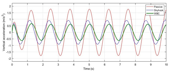
Figure 8.
System response: vertical acceleration of sprung mass () under sinusoidal road excitation, which shows the vertical acceleration of the sprung mass, comparing passive, ideal skyhook, and WBC-assisted active suspension systems.
As shown in Figure 8, the WBC achieves an average oscillatory acceleration peak of approximately 0.65 m/s2. In comparison, the skyhook and passive suspension models exhibit higher values of around 0.9 m/s2 and 1.75 m/s2, respectively. This indicates that the WBC-assisted active suspension improves ride comfort by approximately 63% compared to the passive suspension model and by 28% compared to the skyhook model.
The final test to evaluate the performance of the active suspension system using WBC in comparison to an ideal skyhook model and a passive system with identical suspension characteristics involved a random road input, as depicted in Figure 9. The randomly generated input represents a superposition of step, pulse, and harmonic functions applied over varying time domains.
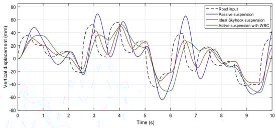
Figure 9.
Response of the sprung mass (Ys) to a randomly shaped road input, presenting the response for comparing passive, ideal skyhook, and WBC-assisted active suspension systems.
When evaluating the actuator controller’s ability to track displacement under random road input conditions, both the WBC and skyhook models exhibit comparable performance. However, similar to the results observed with the previous road inputs, the active suspension system using WBC demonstrates superior control of the vertical acceleration of the sprung mass (), effectively dampening peak values under random road excitation. This is clearly illustrated in Figure 10.
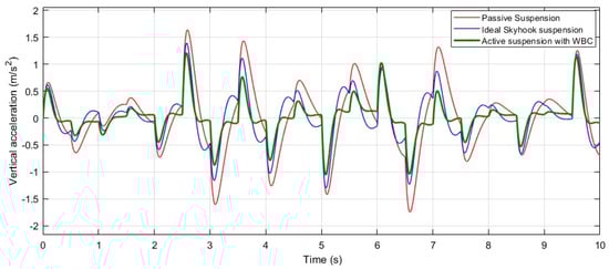
Figure 10.
System response: vertical acceleration of sprung mass () under the random road excitation in Figure 9.
Despite the clear differences in the performance of the three models in response to the random road input, the Root Mean Square (RMS) values of the sprung mass acceleration over the 10 s runtime were calculated and are presented in Figure 11 to provide a more precise comparison. The final RMS values at t = 10 s clearly demonstrate that the active suspension system controlled by the WBC offers superior performance compared to both the passive suspension system and the ideal skyhook suspension system. This highlights its ability to deliver a higher level of ride comfort under irregular and uneven road conditions, as defined by the random road input.
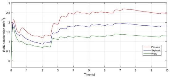
Figure 11.
Variation of the RMS acceleration of the system response of sprung mass acceleration () under the random road excitation shown in Figure 9.
At the end of the runtime, the RMS values of sprung mass acceleration were approximately 2.5 m/s2 for the passive system, 1.8 m/s2 for the skyhook system, and 1.3 m/s2 for the WBC system. These results indicate that the WBC provides significantly improved ride comfort, with reductions of approximately 48% and 28% compared to the passive and skyhook systems, respectively.
In addition to demonstrating the applicability of WBC to suspension dynamics, this study also opens the door to potential cost-effective implementations. Unlike many modern active suspension systems that rely on complex state feedback, high-fidelity modeling, and dense sensor–actuator networks, WBC offers a unique advantage through its co-located sensing-actuation and propagation-based control approach. These features inherently reduce the need for extensive hardware and computational resources, which are major contributors to the high cost of conventional active systems. While this study does not aim to present a full cost analysis, the promising performance achieved with minimal sensing infrastructure suggests that WBC could be a viable alternative in applications where cost, weight, or complexity constraints exist. Part of future work is focused on evaluating the real-world implementation costs and conducting hardware-in-the-loop testing to assess the practical viability of WBC in vehicle suspension systems.
5. Conclusions
This study highlights the excellent efficiency and performance of the WBC approach in rapidly controlling vibrations and vertical acceleration in an active suspension system. Compared to the passive and ideal skyhook suspension models, the WBC approach delivers superior ride comfort for passengers. It achieves the greatest reduction in both vertical displacement and acceleration of the sprung mass when used as the actuator controller.
While the present study primarily focused on the feasibility of applying WBC to suspension systems, an initial sensitivity analysis was conducted. This analysis subjected the system to various road excitation profiles, including pulse, sinusoidal, and random inputs. The goal was to ensure a more comprehensive robustness evaluation of the WBC-assisted active suspension system’s performance across a range of typical disturbances encountered in real-world driving conditions.
Regarding the response to the pulse road input, the WBC-based active suspension system demonstrated superior control performance across two critical metrics: initial overshoot and settling time. Both of these factors were minimized, and the active controller delivered over 38% better ride comfort compared to the ideal skyhook model when subjected to a pulse road input. In terms of response to sinusoidal and random inputs, WBC achieved improvements of approximately 28% over the skyhook model in both cases. These notable advancements were accomplished without relying on additional damping within the system or requiring extra sensors beyond the actuator–sprung mass interface. Hence, the WBC strategy proved itself in multiple successful tests as a novel and cost-effective control technique for active suspension systems, requiring only the measurement of vertical displacements of the sprung and unsprung masses. It is straightforward to implement and offers a range of compelling attributes, including robustness to road input variations, rapid response, minimal overshoot, quick settling, and zero steady-state error—all achieved through a simple, low-order controller.
Furthermore, this intuitive wave-based control method remains robust to system variations and actuator dynamic limitations, ensuring consistent precision with minimal sensing. Its effectiveness is not dependent on a detailed system model, which enhances its practicality and ease of implementation in real-world applications.
In conclusion, the WBC approach presents an innovative, highly efficient solution for active suspension control, offering significant improvements in ride comfort and system performance without the complexity and costs associated with traditional methods. It stands as a testament to the potential of this adaptive, model-independent control strategy in advancing suspension technology.
Future research will extend the current two-degrees-of-freedom formulation to a multi-degree-of-freedom model with full vehicle suspension, not only to evaluate the scalability and spatial coupling behavior of WBC in suspension systems, but to explore the impact of increased model fidelity through the inclusion of additional mass–spring–damper segments on control performance. Further efforts will integrate hybrid control strategies, combining WBC with adaptive or model predictive layers to enhance disturbance rejection and real-time responsiveness. In parallel, systematic sensitivity analyses will be conducted to assess robustness against parameter variations, actuator delays, and other road profile uncertainties. Additionally, energy efficiency optimization and hardware-in-the-loop (HIL) testing are planned to assess real-world viability and cost-performance trade-offs in practical implementations.
Funding
This research received no external funding.
Data Availability Statement
The data presented in this study are available upon request from the corresponding author due to privacy.
Conflicts of Interest
The authors declare no conflicts of interest.
Abbreviations
The following abbreviations are used in this manuscript:
| WBC | wave-based control |
| x(t) | actuator position |
| f (t) | actuator interface force |
| c(t) | actuator motion input |
| r(t) | uneven road input |
| a(t) | launch wave (displacement) |
| b(t) | return wave (displacement) |
| Z | actuator force impedance |
| m1 | sprung mass |
| m2 | unsprung mass |
| t | time |
| x1 | movement of the sprung mass |
| x2 | movement of the unsprung mass |
| K | suspension spring stiffness |
| Kt | car tire stiffness |
| C | suspension damper coefficient |
| P | active suspension actuator |
| mu | car’s unsprung mass |
| ms | car’s sprung mass |
| Yr | road input |
| Yu | vertical displacement of mu |
| Ys | vertical displacement of ms |
| vertical velocity of mu | |
| vertical velocity of ms | |
| vertical acceleration of mu | |
| vertical acceleration of ms | |
| suspension actuator force | |
| CSky | skyhook damping coefficient |
References
- Heißing, B.; Ersoy, M. Chassis Handbook; Vieweg+Teubner Verlag Wiesbaden: Wiesbaden, Germany, 2011; Chapter 5. [Google Scholar] [CrossRef]
- Priyandoko, G.; Mailah, M.; Jamaluddin, H. Vehicle active suspension system using skyhook adaptive neuro active force control. Mech. Syst. Signal Process. 2009, 23, 855–868. [Google Scholar] [CrossRef]
- Deshpande, V.S.; Mohan, B.; Shendge, P.D.; Phadke, S.B. Disturbance observer based sliding mode control of active suspension systems. J. Sound Vib. 2014, 333, 2281–2296. [Google Scholar] [CrossRef]
- Kim, D.; Jeong, Y. Road-adaptive static output feedback control of a semi-active suspension system for ride comfort. Actuators 2024, 13, 394. [Google Scholar] [CrossRef]
- Duan, M.; Jia, J.; Ito, T. Fast terminal sliding mode control based on speed and disturbance estimation for an active suspension gravity compensation system. Mech. Mach. Theory 2021, 155, 104073. [Google Scholar] [CrossRef]
- Shen, Y.; Jia, M.; Yang, X.; Liu, Y.; Chen, L. Vibration suppression using a mechatronic PDD-ISD-combined vehicle suspension system. Int. J. Mech. Sci. 2023, 250, 108277. [Google Scholar] [CrossRef]
- Ni, L.; Wu, L.; Zhang, H. Parameters uncertainty analysis of posture control of a four-wheel-legged robot with series slow active suspension system. Mech. Mach. Theory 2022, 175, 104966. [Google Scholar] [CrossRef]
- Puliti, M.; Galluzzi, R.; Tessari, F.; Amati, N.; Tonoli, A. Energy efficient design of regenerative shock absorbers for automotive suspensions: A multi-objective optimization framework. Appl. Energy 2024, 358, 122542. [Google Scholar] [CrossRef]
- Mousavi, Y.; Alfi, A.; Kucukdemiral, I.B.; Fekih, A. Tube-based model reference adaptive control for vibration suppression of active suspension systems. IEEE/CAA J. Autom. Sin. 2022, 9, 728–731. [Google Scholar] [CrossRef]
- Lai, J.; Zhang, B.; Qin, A.; Zeng, S. Hierarchical control strategy for active suspension equipped with an electromagnetic actuator. SAE Int. J. Adv. Curr. Pract. Mobil. 2024, 6, 2679–2689. [Google Scholar] [CrossRef]
- Kim, H.; Lee, H. Fault-tolerant control algorithm for a four-corner closed-loop air suspension system. IEEE Trans. Ind. Electron. 2011, 58, 4866–4879. [Google Scholar] [CrossRef]
- Kim, H.; Lee, H. Height and leveling control of automotive air suspension system using sliding mode approach. IEEE Trans. Veh. Technol. 2011, 60, 2027–2041. [Google Scholar]
- Yu, M.; Evangelou, S.A.; Dini, D. Parallel active link suspension: Full car application with frequency-dependent multi-objective control strategies. IEEE Trans. Control Syst. Technol. 2021, 30, 2046–2061. [Google Scholar] [CrossRef]
- Li, H.; Zhang, Z.; Yan, H.; Xie, X. Adaptive event-triggered fuzzy control for uncertain active suspension systems. IEEE Trans. Cybern. 2019, 49, 4388–4397. [Google Scholar] [CrossRef]
- Liu, Y.; Zeng, Q.; Tong, S.; Chen, C.P.L.; Liu, L. Adaptive neural network control for active suspension systems with time-varying vertical displacement and speed constraints. IEEE Trans. Ind. Electron. 2019, 66, 9458–9466. [Google Scholar] [CrossRef]
- Khan, S.; Horoub, M.M.; Shafiq, S.; Ali, S.; Bhatti, U.N. Optimization of vehicle suspension system using genetic algorithm. In Proceedings of the 2019 IEEE 10th International Conference on Mechanical and Aerospace Engineering (ICMAE), Brussels, Belgium, 22–25 July 2019; pp. 203–207. [Google Scholar] [CrossRef]
- O'Connor, W.J. Wave-like modelling of cascaded, lumped, flexible systems with an arbitrarily moving boundary. J. Sound Vib. 2011, 330, 3070–3083. [Google Scholar] [CrossRef]
- Habibi, H.; O’Connor, W.J. Wave-based control of planar motion of beam-like mass–spring arrays. Wave Motion 2017, 72, 317–330. [Google Scholar] [CrossRef]
- O’Connor, W.J.; Ramos, F.; McKeown, D.J.; Feliu, V. Wave-based control of non-linear flexible mechanical systems. Nonlinear Dyn. 2009, 57, 113–123. [Google Scholar] [CrossRef]
- Khalilpour, S.A.; Khorrambakht, R.; Taghirad, H.D.; Cardou, P. Wave based control of a deployable cable driven robot. In Proceedings of the 2018 6th RSI International Conference on Robotics and Mechatronics (IcRoM), Tehran, Iran, 23–25 October 2018; pp. 166–171. [Google Scholar]
- Liu, Y.; Zhang, K.; Zhang, W.-Z.; Meng, X.-Y. Wave-based vibration control of large cable net structures. Wave Motion 2018, 77, 139–155. [Google Scholar] [CrossRef]
- Khalilpour, S.A.; Taghirad, H.D.; Habibi, H. Wave-based control of suspended cable driven parallel manipulators. In Proceedings of the 5th IEEE International Conference on Control, Instrumentation and Automation (ICCIA2017), Shiraz, Iran, 21–23 November 2017. [Google Scholar]
- Habibi, H.; O’Connor, W.J. Wave-based motion and slewing control of a double-appendage, flexible system with ungrounded actuator through development of direct actuator force control. Mech. Syst. Signal Process. 2020, 137, 106175. [Google Scholar] [CrossRef]
- Habibi, H.; O’Connor, W.J. Payload motion control of rotary gantry and luffing cranes using mechanical wave concepts. Trans. Inst. Meas. Control 2017, 39, 1649–1662. [Google Scholar] [CrossRef]
- O’Connor, W.J.; Habibi, H. Gantry crane control of a double-pendulum, distributed-mass load, using mechanical wave concepts. Mech. Sci. 2013, 4, 251–261. [Google Scholar] [CrossRef][Green Version]
- Zhou, J.; Zhang, K.; Hu, G. Wave-Based Control of a Crane System with Complex Loads. J. Dyn. Syst. Meas. Control 2017, 139, 081016. [Google Scholar] [CrossRef]
- O’Connor, W.J.; McKeown, D.J. Time-optimal control of flexible robots made robust through wave-based feedback. ASME J. Dyn. Syst. Meas. Control 2011, 133, 011006. [Google Scholar] [CrossRef]
- Magliacano, D.; Viscardi, M.; Dimino, I.; Concilio, A. Active vibration control by piezoceramic actuators of a car floor panel. In Proceedings of the ICSV23: 23rd International Congress on Sound and Vibration, Athens, Greece, 10–14 July 2016. [Google Scholar]
- Magliacano, D.; Viscardi, M.; Ciminello, M.; Dimino, I.; Concilio, A. Feasibility study for a tonal vibration control system of a mounting bracket for automotive gearboxes. Int. J. Mech. 2016, 10, 403–410. [Google Scholar]
- Liu, C.; Lai, S.K.; Ni, Y.Q.; Chen, L. Dynamic modelling and analysis of a physics-driven strategy for vibration control of railway vehicles. Veh. Syst. Dyn. 2024, 1–31. [Google Scholar] [CrossRef]
- Yang, Y.; Liu, C.; Chen, L.; Zhang, X. Phase deviation of semi-active suspension control and its compensation with inertial suspension. Acta Mech. Sin. 2024, 40, 523367. [Google Scholar] [CrossRef]
Disclaimer/Publisher’s Note: The statements, opinions and data contained in all publications are solely those of the individual author(s) and contributor(s) and not of MDPI and/or the editor(s). MDPI and/or the editor(s) disclaim responsibility for any injury to people or property resulting from any ideas, methods, instructions or products referred to in the content. |
© 2025 by the author. Licensee MDPI, Basel, Switzerland. This article is an open access article distributed under the terms and conditions of the Creative Commons Attribution (CC BY) license (https://creativecommons.org/licenses/by/4.0/).