Abstract
This paper presents an automatic oil sampling system designed for vertical cylindrical oil tanks on land, focusing primarily on the structural design and control optimization for oil level measurement and liquid sampling inside the tank. First, the key structure and control architecture of the automatic sampler are introduced, explaining the collaborative working principles of its components to ensure good stability in system structure and motion control. On this basis, an improved Sparrow Search Algorithm (CSSA) is proposed, which integrates the Coati Optimization Algorithm (COA) and the traditional Sparrow Search Algorithm (SSA). This algorithm is used to optimize the parameters of the Proportional–Integral–Derivative (PID) control system in the oil sampler, aiming to address issues such as response delay, large overshoot, and insufficient stability that commonly occur in traditional PID control under complex conditions. This method achieves consistent response behavior over time and adaptiveness in the control process by dynamically adjusting the PID parameters in real time. To verify the effectiveness of the proposed control strategy, system simulations were conducted in the MATLAB 2024B environment, and a physical experimental platform was built for testing. The simulation compares the CSSA-PID controller with traditional PID, COA-PID, and SSA-PID control methods. In addition, a load disturbance was introduced at 300 ms to perform anti-interference comparative simulations. The results show that under CSSA-PID control, the system response time was shortened by up to 112 ms, the convergence speed improved by 72.3%, the global optimization capability was significantly enhanced, and the anti-interference ability was stronger. In the actual tests, the average error was reduced by approximately 45.3%. These results indicate that CSSA-PID can significantly enhance the stability and response speed of the control system. The efficient control of the automatic oil sampler will greatly enhance the intelligence and efficiency of oil level detection in tanks and reduce labor costs, having significant implications for the development of the grain and oil storage industry.
1. Introduction
With the development of industrial intelligence and the trend toward lightweight control systems, achieving high-reliability and high-precision automated operations in complex field environments has become a research hotspot [1,2]. Against this backdrop, the development of intelligent equipment tailored to specific industrial scenarios has gradually become a key direction for improving production quality and safety [3,4,5]. In the grain and oil storage industry, food security has attracted global attention, as it is directly related to economic development, social stability, and national security. Therefore, ensuring the quality and safety of grain and oil reserves is of paramount importance [6,7,8,9]. Among the critical tasks, accurate oil level measurement and stratified oil sampling in land-based vertical, cylindrical tanks are essential for ensuring product quality, safe storage and transportation, and regulatory compliance. However, the currently widespread manual sampling methods suffer from low measurement accuracy, poor sampling consistency, and high operational risks, which severely limit operational efficiency and data reliability.
To address these manual sampling challenges and align with the trend toward automation, this paper presents the design of an automatic oil sampling machine. It can perform height measurement and oil sampling within tanks precisely, efficiently, and safely, significantly improving the quality and efficiency of these operations. In recent years, some studies have begun exploring the design and improvement of automatic sampling equipment. For example, Endress and Hauser [10] launched the Proservo NMS81 smart tank gauge, which employs servo control technology to achieve high-precision level measurement and is widely used in inventory management and loss control in the petrochemical industry. Additionally, Fushun Guangming Technology Co., Ltd. developed a fully automatic liquid tank arbitrary height sampling system, which uses PLC-controlled servo motors to achieve precise sampling at any desired height within a storage tank. However, most of these studies focus on structural design, and systematic optimization of control system dynamic accuracy remains relatively weak. In highly nonlinear, high-inertia applications like oil tanks, traditional PID control suffers from slow response, large overshoot, and difficulty adapting to different tank types or fluid depths. Furthermore, mainstream research has not yet fully incorporated lightweight intelligent optimization algorithms for online controller tuning, especially under the multi-objective fusion strategy of “system stability + response characteristics + embedded real-time performance.” Moreover, because tank sampling operations are low frequency with sparse data, there are insufficient training samples, making deep learning methods unsuitable. Industrial storage tanks are also often enclosed metal spaces where IoT communication is unreliable and redundant, failing to meet stability and cost requirements. In recent years, swarm intelligence optimization algorithms have been widely applied in controller parameter optimization due to their advantages such as not requiring precise mathematical models and strong adaptability. For example, the Genetic Algorithm (GA) achieves global optimization by simulating the process of biological evolution, but it suffers from slow convergence and a tendency toward premature convergence in later stages. Particle Swarm Optimization (PSO) [11], based on cooperative search within a population, converges quickly but is prone to falling into local optima in high-dimensional spaces. The Gray Wolf Optimizer (GWO) [12] and Whale Optimization Algorithm (WOA) [13] perform well in global exploration but still have room for improvement in local fine search accuracy and adaptability to complex systems. Therefore, given the particular characteristics of the oil sampling machine system—such as low-frequency operation, embedded computational constraints, and strong nonlinear disturbances—an optimization algorithm that combines both global search capability and local search precision is needed to achieve efficient PID parameter tuning.
In recent years, the Sparrow Search Algorithm (SSA) has emerged as a novel swarm intelligence optimization algorithm inspired by the foraging and vigilance behaviors of sparrows. The SSA demonstrates excellent global search capability and convergence performance and has shown strong competitiveness in various optimization problems, particularly in function optimization, feature selection, and parameter tuning. However, the SSA still suffers from certain limitations, such as relatively slow convergence in the early stages and a tendency to fall into local optima [14], especially when applied to systems with complex search spaces or significant noise interference. In contrast, the Coati Optimization Algorithm (COA), as a recently proposed bio-inspired algorithm, simulates the territorial competition and foraging behaviors of coatis. It offers stronger global exploration ability and better population diversity maintenance, enabling it to effectively escape local optima. However, its local convergence accuracy and iteration efficiency are relatively weaker [15]. Based on this, this paper proposes an improved Sparrow Search Algorithm (CSSA) that integrates the COA and SSA. Through a “two-stage cooperative optimization” mechanism, PID parameters are optimized: in the first stage, the COA’s advantage in global exploration is leveraged to broaden the search space and avoid local optima; in the second stage, the SSA’s local exploitation capability is introduced to enhance the precision of parameter tuning. This hybrid strategy not only retains the breadth of the COA’s global optimization but also strengthens the depth of the SSA’s local search, effectively addressing the shortcomings of traditional PID control in the oil sampling machine system.
In the past few years, numerous researchers have focused on improving the Sparrow Search Algorithm and have proposed a variety of effective enhancement strategies. Zhang [16] designed a PID controller based on an improved sparrow algorithm for stepper motor control, which enhanced the motor’s response speed and the robustness of speed control. Zhang [17] proposed a multi-strategy improved Sparrow Search Algorithm (ISSA) that enhances the anti-interference ability of the crane control system by introducing Levy flight and an adaptive weight optimization PID controller. Zhu [18] integrated a random walk strategy into the Sparrow Search Algorithm to optimize PID parameters for use in a chilled water system, effectively reducing the system’s time delay and inertia. Ouyang [19] designed an improved Sparrow Search Algorithm to optimize PID parameters and address the strong coupling and large time delay in continuous reactor temperature control; experiments demonstrated that the proposed ISSA-PID controller exhibited stable performance and high control precision. Zhang [20] proposed an improved Sparrow Search Algorithm for PID parameter tuning, which enhanced the algorithm’s global search ability and local escape capability while improving the response speed and stability of PID control. Zhao [21] designed an enhanced Sparrow Search Algorithm for microgrid operation planning, which effectively reduced energy consumption and lowered the operation and maintenance costs of the grid. Wang [22] combined the Genetic Algorithm with the Sparrow Search Algorithm to propose a hybrid Sparrow Search Algorithm (HSSA), which was applied to industrial robot control to improve stability and safety. Jin [23] incorporated human learning mechanisms into the Sparrow Search Algorithm to increase population diversity and added a warning strategy to strengthen local search capability.
To enhance the anti-interference capability and system stability of the oil sampler, and to improve its measurement accuracy, this paper proposes an improved Sparrow Search Algorithm (CSSA) for PID parameter optimization. The main contributions of this paper are as follows:
- A compact, high-precision, and low-cost automatic oil sampler was designed for measuring the oil depth and collecting liquid samples inside land-based cylindrical oil storage tanks.
- The Coati Optimization Algorithm (COA), known for its strong global search capability, is used to improve the Sparrow Search Algorithm (SSA), which lacks sufficient global search ability, thereby enhancing its capability to escape local optima.
- In the traditional PID control system of the oil sampler, the CSSA is used to optimize the PID parameters, enhancing its ability to find the optimal solution, improving the system’s stability, and increasing measurement accuracy.
The structure of this paper is arranged as follows: Section 2 introduces the structural design of the main components of the oil sampler. Section 3 describes the design of the control system and explains the working principle of the oil sampler. Section 4 presents the implementation principle of the improved Sparrow Search Algorithm (CSSA). Section 5 applies the CSSA to optimize the PID parameters, followed by simulation and experimental testing of the oil sampler. Section 6 provides the conclusion.
2. Oil Sampling Machine Structural Design
The automatic oil sampling machine is an automated device specifically designed and developed for oil tank operations, with its core function focused on accurately measuring the liquid level and efficiently collecting oil samples from large, vertical, cylindrical land-based oil storage tanks. The oil sampling machine can automatically measure the depth of the liquid inside the oil tank and perform sampling at three different levels—upper, middle, and lower—based on the measured liquid depth. Additionally, to address the issue of oil residue left on traditional oil measurement sticks after use, a special oil scraping device has been designed to effectively remove any residual oil, preventing contamination and errors in subsequent measurements and oil quality analysis. Further-more, this automatic oil sampling machine is equipped with highly intelligent automatic control capabilities, allowing it to precisely control the sampling device to collect oil samples from different depths within the tank according to preset programs. This ensures that the collected oil samples comprehensively, accurately, and representatively reflect the characteristics and quality of the oil at different levels within the tank. The overall structural diagram is shown in Figure 1 and Figure 2.
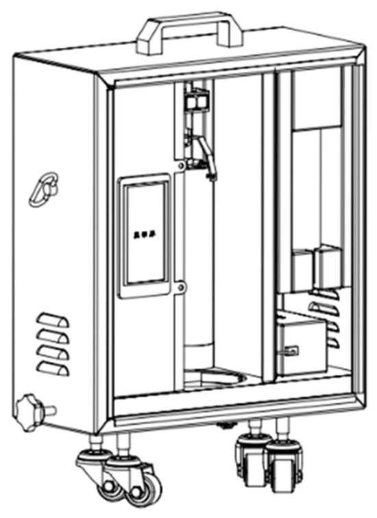
Figure 1.
Oil sampling machine appearance diagram.
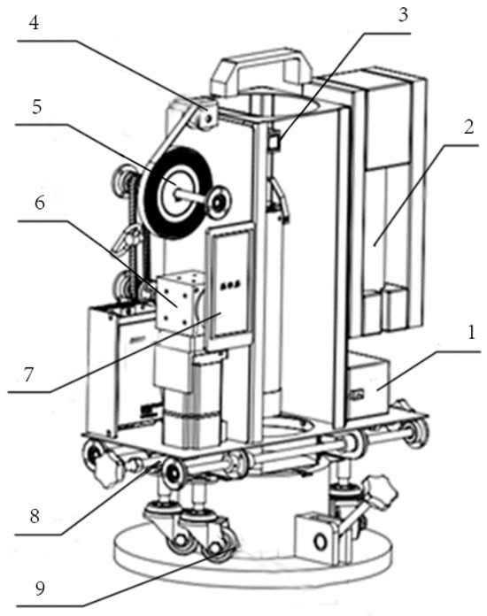
Figure 2.
Internal structure diagram of oil sampling machine: 1. 24V lithium battery; 2. sampler; 3. oil scraper; 4. pressure sensor; 5. oil measuring gauge; 6. motor; 7. touch screen; 8. telescopic buckle; 9. adjustable support wheel.
The oil sampling machine designed in this project adopts a unique box-type structure for its overall appearance and frame. In the design of the box, great attention is given to the convenience of installing internal components and the operation of retrieving and placing the sampler. Therefore, the front is designed with a side cover that can be flipped up and down [24]. With this side cover design, when installation or maintenance of various components inside the box, such as the motor, measuring tape, and sensors, is required, the side cover can be easily opened, making the work more convenient. Additionally, the retrieval and placement of the sampler are made much easier and more efficient. The overall dimensions of the box have been carefully planned and designed, with a length, width, and height of 400 mm, 180 mm, and 500 mm, respectively. This size ratio ensures that there is enough space inside to accommodate the relevant components while giving the entire oil sampling machine a compact and tidy appearance. When the oil sampling machine is in operation, the first step is to adjust the telescopic buckle to tightly fasten the oil tank opening wall, ensuring the stability and safety of the sampling process. Then, depending on the actual working conditions and the specific height of the oil tank opening, the support wheels are adjusted to the appropriate height and locked in place, providing a stable and reliable foundation for the entire oil sampling machine during its operation. Table 1 presents a performance comparison between the proposed system and three mainstream oil sampling devices: manual rod lifting, PLC-based rail arm type, and servo rotary type.

Table 1.
Performance comparison.
From the table, it can be seen that the oil sampler designed in this paper maintains high control accuracy and complete functionality while offering good cost effectiveness, compact size advantages, and compatibility with oil tanks. It is particularly suitable for the vertically cylindrical oil tanks commonly used in the grain and oil storage and transportation industry.
2.1. The Structural Design of the Oil Scraping Device
During an in-depth on-site observation of the manual sampling operation process in the oil depot, we identified a prominent issue that urgently needs to be addressed. Each time an oil height measurement is conducted, the measuring tape, after being immersed in the oil tank and retrieved, is always covered with a significant amount of oil. To deal with this issue, the current method requires two workers to collaborate: one worker focuses on slowly retracting the measuring tape while the other holds a paper towel, carefully wrapping the tape and repeatedly wiping and squeezing it to remove the oil residue. This traditional approach is not only labor intensive but also poses safety risks due to direct hand contact with the measuring tape. To effectively overcome this challenge in oil depot sampling operations, this paper innovatively designs an automatic device specifically for scraping oil off the measuring tape. The core working principle of this device relies on an electric push rod to precisely operate a linkage mechanism, which, in turn, skillfully controls the opening and closing movements of the oil scraping foam. The structural diagram of the oil scraping device is shown in Figure 3:
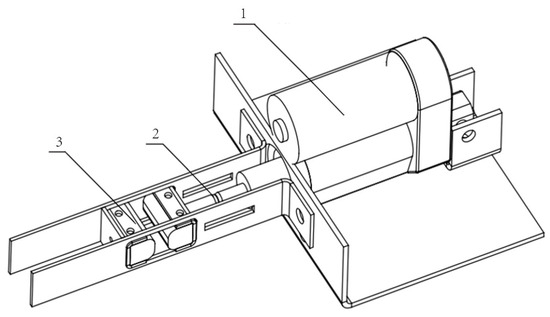
Figure 3.
Overall structural diagram of the oil scraping device: 1. electric push rod; 2. stud; 3. foam.
2.2. Motor Power Section Structural Design
The motor power section is considered the core and key component of the automatic oil sampling machine. A permanent magnet synchronous servo motor is selected as the power source due to its significant advantages, such as fast response speed and high control precision [25]. It can precisely adjust output power and speed according to different operational requirements. The addition of a reducer effectively regulates the motor’s out-put speed, ensuring it meets the working speed requirements of the oil measuring gauge while maintaining the overall stability and reliability of the system. Additionally, a synchronous belt with a 1:1 transmission ratio is used, ensuring smooth power transmission and making the extension and retraction movements of the oil measuring gauge more stable and precise. The structural diagram is shown in Figure 4:
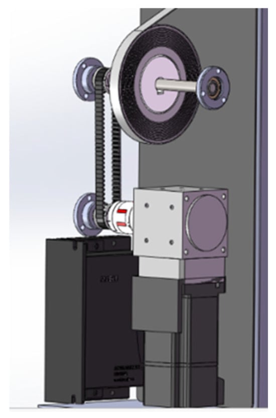
Figure 4.
Overall structural diagram of the oil sampling machine power unit.
2.3. Telescopic Fixed Buckle Structural Design
To ensure a more stable installation of the machine on the platform at the oil tank opening, this design introduces an innovative **telescopic fixed buckle structure. During actual operation, the operator can easily rotate the handles on both sides to achieve lateral movement of the clamping ring. This ingenious design mechanism allows the operator to flexibly adjust the distance between the arc-shaped plate and the tank opening wall according to the specific size of different oil tank openings. The structural diagram of the telescopic fixed buckle is shown in Figure 5:
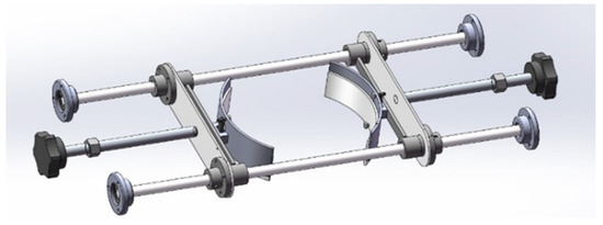
Figure 5.
Structural diagram of the telescopic fixed buckle.
2.4. Design of the Visual Operating Interface
To achieve more convenient and efficient integrated operation of the oil sampling machine, the author designed a visual operation interface. This interface organically integrates the precise oil height measurement function and the automatic oil sampling function, allowing the operator to easily complete both important tasks on the same interface. For the hardware platform, a serial touch screen was chosen for the operation interface. The serial touch screen offers excellent human–machine interaction capabilities, and its intuitive operation method enables operators to quickly get started. It establishes a stable connection with the microcontroller via communication lines, ensuring the reliability of data transmission. The oil sampling machine operation interface is shown in Figure 6:
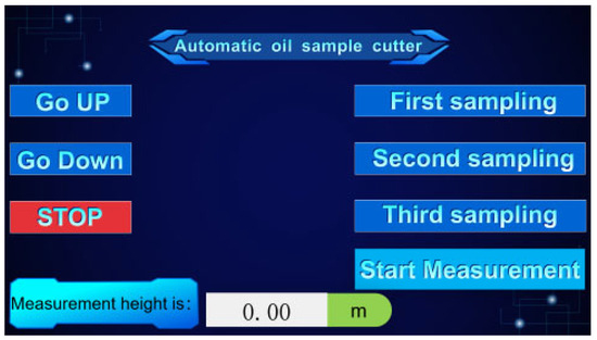
Figure 6.
Visualization interface diagram.
3. Design of the Oil Sampling Machine Control System
The control system of the oil sampler serves as the core hub for the precise and stable operation of the entire equipment. Its primary goal is to achieve high-precision control of the various mechanical components of the oil sampler, thereby meeting the diverse requirements of oil sampling operations under different working conditions. From a technical implementation perspective, leveraging advanced sensor technology, mature and reliable control algorithms, and efficient and convenient communication methods enables precise and accurate manipulation of key components such as motors, transmission devices, and measurement instruments [26]. The overall block diagram of the oil sampler control system is shown in Figure 7.
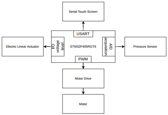
Figure 7.
Control system connection diagram.
For the design of this oil sampler, a permanent magnet synchronous servo motor was deliberately selected as the power source to drive the measuring tape, considering the motor’s outstanding performance in precise control. The main control system uses the STM32F405RGT6 chip as the central controller, which offers powerful computing capability and abundant interface resources to effectively handle complex control tasks. Due to the significant differences in buoyancy acting on the lead weight when it is in the air, just touching the liquid surface, and reaching the bottom of the oil tank, a pressure sensor is employed to closely monitor sudden changes in the pulling force on the lead weight at these special positions and to provide real-time feedback to the microcontroller. Based on this data, the microcontroller accurately calculates the specific position of the measuring tape inside the oil tank, thereby determining the precise start–stop points of the motor and the timing for data recording.
The oil tank height measurement flowchart is shown in Figure 8. After the worker completes the installation of the oil sampling machine and starts the motor, the plumb bob begins to descend slowly. The moment the plumb bob first touches the liquid surface, the buoyancy force acting on it changes. The connected pressure sensor detects this sudden physical change and promptly converts the signal into an electrical signal, transmit-ting it to the microcontroller control center. As the core control unit of the entire system, the microcontroller immediately activates the pre-programmed motor travel calculation algorithm upon receiving the signal from the pressure sensor. This program, based on advanced algorithms, precisely analyzes and calculates the motor’s operating parameters to quickly determine the travel distance from the initial position to the moment the plumb bob first enters the liquid surface. This measured value corresponds exactly to the height H1, which represents the distance from the oil tank opening to the oil surface. The system then automatically records this height with high accuracy for further data processing and analysis.
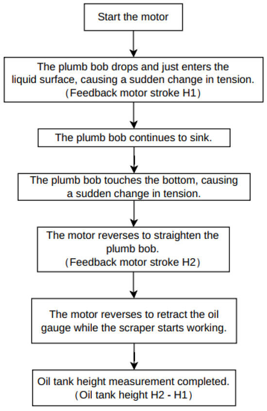
Figure 8.
Oil tank height measurement flowchart.
After recording the height H1, the motor continues its descent until the plumb bob steadily settles at the bottom of the oil tank. It is important to note that the plumb bob used with the oil measuring gauge has a specific 20 cm scale marking and lies flat upon reaching the tank bottom. This unique characteristic may affect measurement accuracy. To ensure precise and reliable data, the oil measuring gauge needs to be realigned. When the pressure sensor detects another abrupt change in force—caused either by the plumb bob’s posture shift or its contact with the bottom—the motor automatically triggers a reverse command, lifting the oil measuring gauge. During its ascent, the moment the plumb bob just detaches from the oil sludge layer, a distinct signal change is detected due to the physical differences between the oil sludge and the liquid oil. At this point, the microcontroller recalculates the motor’s travel distance, which corresponds to the height H2, the distance from the tank opening to the sludge surface. By simply subtracting H1 from H2, the actual oil level height inside the tank can be precisely determined. This measurement method fully utilizes the high sensitivity of the pressure sensor and the powerful data processing capabilities of the microcontroller. It effectively eliminates potential errors and inconveniences found in traditional measurement techniques, significantly improving the accuracy and efficiency of oil level measurement. This provides reliable data support for oil storage, management, and transportation processes.
Calculation rules for motor travel distance: The selected brushless DC motor has 4 pole pairs, and it is equipped with three Hall sensors. When the rotor’s magnetic poles pass over the Hall sensors, the sensors output corresponding logic levels 0 or 1. By analyzing the output signals of the three Hall sensors, the rotor’s position can be determined [27]. For each full rotation of the motor, the Hall sensors undergo 4 × 6 high-low level transitions. Therefore, by counting the number of Hall pulses (n), the number of motor rotations can be determined. However, since a 30:1 gearbox is installed in front of the motor, the motor shaft must rotate 30 times for the load shaft to complete one full rotation. By knowing the linear distance traveled per full rotation of the load shaft, the total linear travel distance (Hn) of the oil measuring gauge can be calculated.
Calculation of the motor shaft’s rotation count (Cm):
In the formula, n represents the detected Hall pulse count, and Pn represents the number of Hall pulses per full rotation of the motor shaft, which is 24 pulses.
Calculation of the load shaft’s rotation count (Ct):
In the formula, i represents the gear reduction ratio, which is 30:1.
Determination of the oil measuring gauge travel distance (Hn):
In the formula, L represents the linear distance corresponding to one full rotation of the load shaft.
After successfully obtaining the height above the liquid surface (H1) and the distance from the tank opening to the oil sludge surface (H2) based on the precise calculation formulas mentioned above, the accurate oil level height (H) inside the tank can be further determined. This height data plays a crucial guiding role in the subsequent oil sampling operations. According to the sampling standards for animal and vegetable oils specified in GB/T 5524-2008 and ISO 5555:2001 [28], the “top” sample should be collected at one-tenth of the total depth, the “middle” sample at one-half of the total depth, and the “bottom” sample at nine-tenths of the total depth. Additionally, the “middle” sampling position requires three samples to be taken. In the actual operation process, the intelligent control program precisely drives the motor to move the sampling bucket, which is closely connected to the measuring tape, smoothly to the designated heights h1, h2, and h3 for sampling. Once the sampling bucket reaches the preset height, it remains stationary for 5 s to ensure that the sampling process is sufficient and complete, allowing representative oil samples to be accurately collected from each layer. After sampling is completed, the motor immediately reverses to orderly lift the sampling bucket, thus successfully completing the entire sampling process. The oil sampling flowchart is shown in Figure 9.
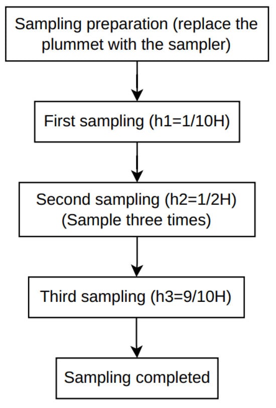
Figure 9.
Oil sampling flowchart.
4. Optimization of the Oil Sampling Machine Control System
The automatic control system of the oil sampling machine consists of both hardware and software components. The hardware system includes key components such as the STM32F405RGT6 microcontroller, pressure sensor, permanent magnet synchronous motor, and electric actuator. The software system utilizes Keil uVision5 software for microcontroller programming in C language [29]. Adopting a modular programming approach, the system is divided into modules such as motor drive, sensor data processing, height calculation and control, and sampling operations. These modules work collaboratively to ensure the intelligent operation of the oil sampling machine.
Although the traditional classical PID algorithm used in the original control program has advantages such as a simple principle, broad adaptability, and easy implementation and tuning of parameters, it struggles to meet the intelligent control requirements for oil level measurement. This is due to interference from nonlinear factors during the operation of the oil sampler, such as oil type, depth, and the thickness of sludge at the tank bottom. To address this issue, without altering the hardware structure, this study introduces the Sparrow Search Algorithm (SSA) and the Coati Optimization Algorithm (COA) into the microcontroller’s software control program. By integrating the SSA and COA into a fused CSSA to optimize the traditional PID parameters (Kp, Ki, and Kd), the system can enhance the accuracy and stability of the servo motor’s speed adjustment process. This enables precise control of both oil level measurement and sampling speed.
4.1. Traditional PID Control System
In the intelligent control process of the oil sampling machine, the traditional PID algorithm is implemented through the microcontroller control program and applied to each critical stage. Whether it is the precise measurement of the oil storage height in the tank or the delicate operation of oil sampling, speed regulation plays a crucial role. When the oil sampling machine is in operation, for instance, transitioning from air into oil, the motor needs to adjust its speed based on the pressure variations detected by the pressure sensor. While moving within the oil, the motor’s speed regulation relies on the height information fed back by the Hall sensor. As the oil sampling machine approaches the oil surface, the pressure it experiences undergoes subtle changes. The pressure sensor can promptly capture these variations and transmit the data to the STM32 central controller, enabling the motor to make pre-emptive speed adjustments. This ensures a smooth operation process, thereby guaranteeing measurement accuracy. The structure of the traditional PID algorithm is shown in Figure 10, where R(s) represents the input target value, U(s) is the actual output value, and Y(s) is the measured actual value.

Figure 10.
Block diagram of the traditional PID algorithm structure.
The general expression for the transfer function of the traditional PID mathematical model used in the oil sampling machine control system is:
where Kp is the proportional coefficient, Ki is the integral coefficient, and Kd is the derivative coefficient. The traditional PID algorithm is used to adjust various parameters of the oil sampling machine system to ensure excellent dynamic performance during operation, meeting measurement and detection requirements.
4.2. Coati Optimization Algorithm (COA)
Based on the social habits of coati populations, Dehghani [30] proposed the Coati Optimization Algorithm (COA), a novel bio-inspired intelligent optimization algorithm. The algorithm is inspired by the foraging behavior and territorial competition mechanism of coatis. The core idea of the COA is to simulate coatis’ behaviors during the two main phases of exploration and exploitation, including foraging, territory marking, and antagonistic interactions, to achieve a balance between global search and local fine-tuning. These characteristics closely resemble the process of solving global optimization problems. Therefore, the COA can be effectively applied to various optimization tasks such as parameter tuning, path planning, neural network training, and control system optimization. The complete implementation flow of the COA is illustrated in Figure 11.
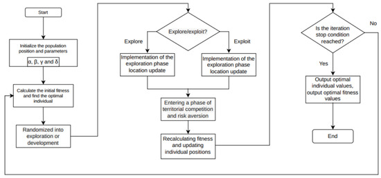
Figure 11.
COA flowchart.
4.3. Sparrow Search Algorithm (SSA)
The Sparrow Search Algorithm (SSA) was proposed by Xue and Shen in 2020. Its core idea is to balance global exploration and local exploitation by simulating the collaborative pattern between “producers” and “followers” as well as the “vigilant anti-predation” behavior. The algorithm offers advantages such as a small number of parameters, fast convergence speed, and strong robustness, and it has been widely applied in fields including engineering optimization, machine learning, and path planning.
In the foraging phase of producers within the SSA, the proportion of producer individuals in the entire sparrow population is relatively small. These producers exhibit higher adaptability, are responsible for locating and providing food sources, and guide the whole sparrow population toward promising regions. The position of producers is updated according to the mathematical model (5):
where, represents the position of the ith sparrow in the jth dimension during the tth iteration, N is the maximum number of iterations, R2 is the alarm value in the range [0, 1], ST is the alarm value in the range [0.5, 1], Q is a normally distributed random number, L is a one-dimensional identity matrix, and is the step size parameter in the range [0, 1].
For the followers, these individuals make up a larger proportion of the sparrow population and generally exhibit lower adaptability. Their main role is to follow the producers to obtain food. The position of the followers is updated according to Equation (6).
In this equation, represents the position of the worst individual in the current population, denotes the position of the best sparrow individual at iteration t + 1, and A is a 1 × D matrix. When i > N/2, it indicates that the ith follower has failed to find food and needs to forage elsewhere; when i ≤ N/2, it indicates that the follower is foraging near the optimal position.
In the vigilance-based danger avoidance phase, warners (or vigilant individuals) make up a small proportion of the entire sparrow population, randomly generated within the population, typically accounting for about 10% to 20%. When a warner perceives danger (i.e., its fitness falls below a safety threshold), it will escape from the current area. Its position is updated according to Equation (7):
where is the global best position, K is a random number between [−1, 1], fi is the fitness value of the ith sparrow, fg and fw are the current global best and worst fitness values, and is the step size control parameter. When fi > fg, the sparrow is located at the edge of the population; when fi = fg, the sparrow is located at the core of the population.
In summary, the Sparrow Search Algorithm (SSA) possesses strong local search capabilities and is easy to implement due to its relatively few parameters. However, when solving complex problems, it is prone to falling into local optima and lacks robust global search ability. The implementation process of the SSA is shown in Figure 12.
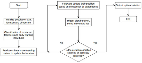
Figure 12.
SSA flowchart.
4.4. Improved Sparrow Search Algorithm (CSSA)
The Sparrow Search Algorithm (SSA) possesses strong local search capabilities and converges quickly; however, it is prone to falling into local optima, which reduces its accuracy in solving global optimization problems. In contrast, the Coati Optimization Algorithm (COA) has excellent global search capability and can efficiently identify optimal solutions within a search space. Therefore, this paper combines the SSA and COA to form an improved Sparrow Search Algorithm, the CSSA, which consists of the following two stages:
Stage One: Global search (COA phase).
The first step of the CSSA is to perform a global search using the Coati Optimization Algorithm (COA). In this phase, an initial population is randomly generated within the solution space, as shown in Equation (8).
In the equation, represents an individual in the population, ubj and lbj are the upper and lower bounds of the search space, respectively, and r is a random number in the interval [0, 1].
After the population is initialized, some coatis will climb trees to drive prey, which represents the optimization units moving toward the optimal solution. The position update is given by Equation (9):
where P1 represents the first phase, the jth dimensional data of the ith coati, is the current optimal position of the prey, r is the scaling factor, and I is a random integer from the set [1, 2].
When the prey feels threatened, it will randomly fall from the tree onto the ground. At this moment, the prey’s position is given by Equation (10).
In the equation, represents the position of the prey after landing.
When the prey lands, the coatis on the ground will attack it. At this time, the position of the coati is updated, as shown in Equation (11).
In the equation, represents the fitness value of the prey after landing, and Fi represents the fitness value of the current coati. The coatis on the ground launch an attack on the prey; when the prey’s position is better, the coatis move toward the prey and otherwise move in the opposite direction. This reflects the global optimization capability of the Coati Optimization Algorithm. Through these steps, the Coati Optimization Algorithm can identify effective regions with high-potential solutions within complex solution spaces. This robustness in large-scale searches and ability to handle nonlinear problems are precisely what the Sparrow Search Algorithm lacks. With this optimization strategy, not only is the discovery of effective regions accelerated, but it also ensures that the algorithm does not fall into local optima during the exploration of various solutions, thereby laying a solid foundation for more detailed subsequent searches.
Stage Two: Local intensive search (SSA phase).
After completing the global search, the second step of the optimization algorithm is carried out. A local search is performed based on the results of the global search by using the Sparrow Search Algorithm (SSA) to find the local optimum. At this stage, the results obtained from the Coati Optimization Algorithm (COA) are used to initialize the sparrow population:
Producers are responsible for exploring these areas, and their position updates follow Equation (13).
where R ∈ [0, 1] is a random number, Qs is the safety threshold for danger detection, γ is the step size control parameter, K is a random step size factor, and represents the current optimal solution.
The followers adjust their positions according to the producers’ location and the foraging area to move to appropriate positions.
In the equation, L and I are step size control parameters, and represents the position of the worst individual. Finally, environmental threat factors are introduced, allowing the sparrows to dynamically adjust their positions in real time based on a safety threshold when a threat is perceived.
In the equation, δ is a random variable that determines the degree of adjustment.
The Sparrow Search Algorithm (SSA) seeks the optimal solution by simulating the living habits of sparrows. Each sparrow individual acquires local information based on the positions of nearby companions and obtains global information based on the distribution of the entire sparrow population. It then adjusts its foraging position accordingly. This method of fine-tuning and narrowing the search space is conducive to identifying the optimal position within the entire solution space, thereby facilitating the discovery of the best solution.
The improved Sparrow Search Algorithm (CSSA) operates through two stages: first, the Coati Optimization Algorithm (COA) is employed to perform global search, identifying promising regions within the solution space that exhibit high potential; then, the Sparrow Search Algorithm (SSA) is used to fine-tune and optimize within these regions to find the final optimal solution. This algorithmic model enables fast and efficient resolution of complex optimization problems. The detailed flowchart of the algorithm is shown in Figure 13.
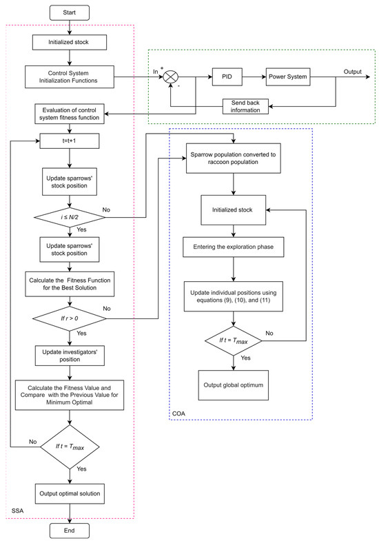
Figure 13.
The implementation process of the CSSA-PID algorithm.
5. Simulation and Experimental Validation of CSSA-PID Control Strategy on an Oil Sampling Machine
To verify the feasibility of the CSSA-PID algorithm, MATLAB simulation experiments were conducted, and a test platform for the oil sampling machine was built for practical testing experiments.
5.1. CSSA-PID Algorithm Testing
In addition, for the intelligent height measurement and oil sample sampling system of the oil cutting machine, this study uses the traditional PID algorithm as the basic algorithm for the control system. Because the control rate output of this algorithm is not continuous in the time domain and is inconvenient to test, the performance of the CSSA is verified by referring to the traditional PID algorithm testing method. Therefore, the fitness function of the control system adopts PID control to adjust the error accuracy and feedback time as the dual index fitness objects and selects the ITAE error criterion as the fitness function of the HSSA, as shown in Equation (16).
This study verifies the CSSA from two dimensions. The first dimension evaluates the algorithm’s iterative convergence speed, while the second assesses the response time and overshoot when a step signal is applied to the algorithm’s input. These results are compared with those of traditional PID, COA-PID, and SSA-PID controllers. To validate the effectiveness of the CSSA, the control system of the oil sampling machine is approximated as a second-order system, and its closed-loop transfer function is simplified as follows:
where K is the gain coefficient, s is the complex frequency variable, ζ is the damping ratio, T1 is the primary time constant, and T2 is the secondary inertia time constant.
The system gain K is primarily determined by the relationship between the motor’s angular displacement θ and the resulting linear displacement L.
The damping ratio ζ is mainly affected by the system’s frictional damping and load inertia. For motor systems with low-friction loads, ζ typically ranges between 0.6 and 0.9. To ensure fast response without oscillation, ζ is set to 0.7 in this study.
By consulting the motor manual, the motor’s rotational inertia J and friction coefficient B are known, from which the main time constant T1 can be obtained:
The second-order inertial time constant T2 can be calculated using the motor torque constant Kt and the rotational inertia J.
In summary, based on Equations (17)–(20), the transfer function model of the oil sampler system can be derived as:
Table 2 presents the experimental parameters used to validate the optimization performance of the CSSA. A population size of 300 was chosen to ensure diversity across the entire search space, which not only accelerates the computation speed but also effectively guarantees global exploration. The maximum number of iterations was set to 500, based on preliminary testing, to ensure effective computation results while avoiding unnecessary computational overhead. For PID parameter selection (Kp, Ki, and Kd), the initial values were set to 3.5, 1.0, and 0.01, respectively, with upper bounds defined as [100, 10, 1] to accommodate the nonlinear characteristics of the oil sampling system. The search dimension was set to 3, corresponding to the three PID parameters. Regarding the Sparrow Search Algorithm, the producer ratio was set to 0.6, the alerter ratio to 0.2, and the safety threshold to 0.7, which helps balance the sparrow population’s exploration of the solution space.

Table 2.
Simulation test parameters.
Figure 14 shows the step response experiment of the PID controller. As illustrated in the figure, the overall performance of the CSSA-PID algorithm significantly surpasses that of the SSA-PID, COA-PID, and traditional PID algorithms. Additionally, Table 3 provides a more systematic statistical comparison of key performance indicators such as overshoot and response time. Compared to the traditional PID controller, the CSSA-PID achieves up to a 72.3% improvement in response time and exhibits zero overshoot, whereas all other controllers show some degree of overshoot. The results from both the step response and disturbance rejection experiments demonstrate that the CSSA-PID possesses superior global optimization capability. It effectively suppresses servo motor oscillations during oil level measurement and sampling and also enhances the system’s response speed to a certain extent.
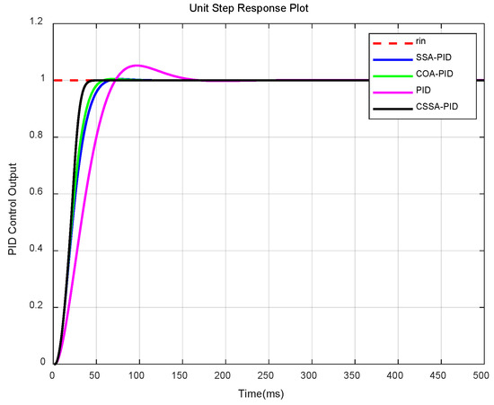
Figure 14.
Simulation results of step input response.

Table 3.
Comparison of control system performances.
To verify the robustness of the proposed control strategy under dynamic disturbance conditions, a sudden load disturbance (simulating abrupt changes in sampling weight or oil surface fluctuations during the oil sampling process) was applied at 300 ms in the simulation. Figure 15 presents the output responses of four control methods: CSSA-PID, SSA-PID, COA-PID, and conventional PID. The conventional PID exhibited significant overshoot and slow recovery. Although SSA-PID and COA-PID provided certain disturbance rejection capabilities, their output fluctuations were more pronounced compared to CSSA-PID. The CSSA-PID control strategy demonstrated the best disturbance suppression performance, with the output quickly returning to the target value, exhibiting the smallest overshoot and shortest settling time. This experiment further validates the robustness and disturbance rejection capability of the proposed method under practical operating conditions.
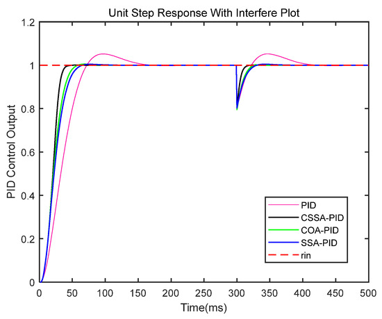
Figure 15.
Simulation results of step input response with load..
Figure 16 shows the iteration convergence results of the SSA, COA, and CSSA. As illustrated, the CSSA clearly outperforms both the SSA and COA in terms of the speed of PID parameter tuning, demonstrating a significant improvement in optimization speed. Compared with the SSA and COA, the CSSA is able to find the optimal solution more quickly. This indicates that the CSSA can better enhance the stability and response speed of the intelligent oil sampling system driven by a servo motor, thereby facilitating high-precision measurement.
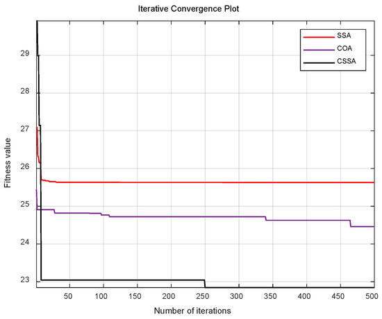
Figure 16.
Iteration count experiment.
5.2. Experimental Testing on the Oil Sampling Machine Equipment Platform
To verify the feasibility of the oil sampling machine design and the superiority of the CSSA-PID control algorithm, a hardware experimental platform for the oil sampling machine was built, as shown in Figure 17. This experimental platform mainly consists of core components such as a pressure sensor, electric actuator, oil gauge, reducer, motor, and sampler. The STM32f405RGT6 microcontroller serves as the control core, enabling the automatic sampling and measurement functions of the oil sampling machine.
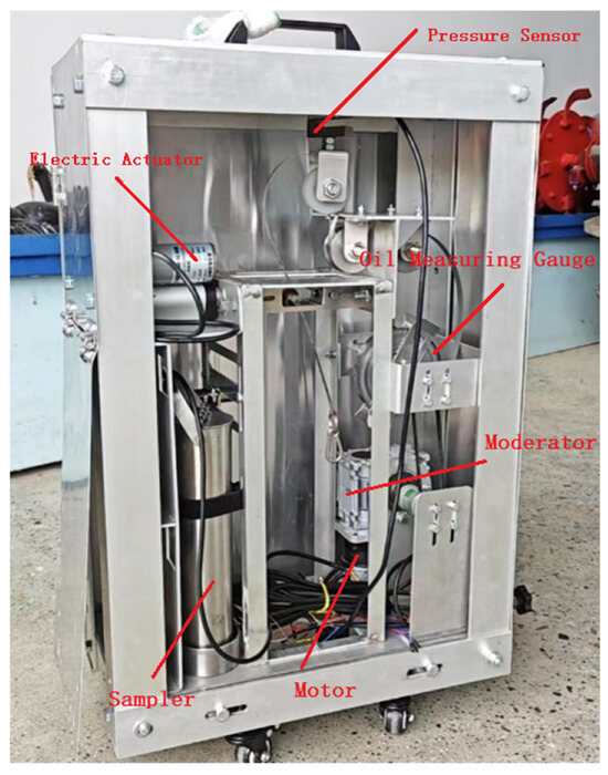
Figure 17.
Physical diagram of the oil sampling machine.
To verify the feasibility of the CSSA-PID control, measurements were conducted at different oil storage depths during the experiment. The target oil levels were set at 10 m, 20 m, 30 m, 40 m, and 50 m, respectively. The oil sampling device was connected to USART-HMI V1.67.2 simulator software via a serial port, allowing for real-time observation of the height data feedback from the microcontroller on the simulator interface for data analysis. The reception effect is shown in Figure 18.
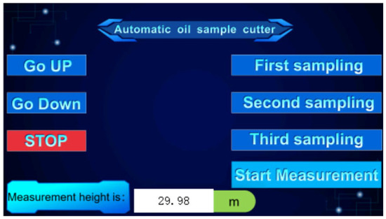
Figure 18.
Reception effect diagram.
Traditional PID and CSSA-PID were used separately for oil level control, and the final measurement results were recorded. The experimental data results are shown in Table 4.

Table 4.
Experimental data comparison results.
Given that this study aims to verify the performance improvements of the CSSA-PID algorithm over conventional PID control, the conventional PID was selected as the baseline for comparison to highlight the performance enhancement. Although SSA-PID and COA-PID are representative intelligent optimization algorithms, their parameter tuning processes are more complex, and their experimental results are not easily unified. To avoid introducing excessive variables, these algorithms were not included in the comparative analysis at this stage. The test results show that for both conventional PID and CSSA-PID control, measurement error increases as the oil depth increases. A qualitative analysis indicates that the system deviation is mainly influenced by environmental factors such as temperature fluctuations inside the oil tank, which may cause changes in oil viscosity and indirectly affect the smooth movement of the measuring ruler, as well as minor airflow or oil surface disturbances that may interfere with the stability of the plumb bob’s force balance. Equipment-related factors, including the nonlinear characteristics of motor response and the inherent noise of sensor signals, may also introduce measurement bias. Furthermore, conventional PID relies on fixed parameters and struggles to adapt in real time when working conditions change dynamically, often resulting in additional errors due to adjustment lag or overshoot. Overall, CSSA-PID control achieved lower measurement errors than conventional PID control, with the average error reduced by approximately 45.3%, significantly improving measurement accuracy. Combined with the simulation results, CSSA-PID control effectively reduces overshoot, enhances response speed, and improves system stability, further validating its superiority over conventional PID control.
6. Conclusions
This study addresses the prominent issues of low efficiency and poor accuracy encountered in manual measurement of oil depth and sampling in vertical, cylindrical land-based oil tanks. To solve these problems, a cost-effective, compact, and high-precision automatic oil sampling machine was independently developed and designed. This device can effectively replace manual operations, enabling precise measurement of oil depth and efficient collection of oil samples.
This paper elaborates on the main structural components and working principles of the automatic oil sampling machine. In terms of control algorithms, to further enhance the measurement and sampling performance of the system, the traditionally used PID control algorithm was optimized. An innovative approach was proposed by integrating the Coati Optimization Algorithm (COA) with the Sparrow Search Algorithm (SSA), forming an improved hybrid algorithm named the CSSA, which was used to optimize the PID parameters. Experimental results demonstrate that the CSSA-PID control algorithm effectively reduces system overshoot, shortens convergence time, and improves system stability. These advantages enable the oil sampler to achieve higher precision during oil measurement and sampling tasks, significantly enhancing the overall operational quality.
However, due to time and experimental constraints, this study still has certain limitations. In future research, further optimization of the mechanical structure of the sampler is needed to improve mechanical stability and sampling reliability. Additionally, the control algorithm can be further enhanced to improve the system’s adaptability and measurement accuracy, thereby strengthening its robustness and real-time responsiveness under complex working conditions. Moreover, although the designed automatic oil sampler primarily targets the oil measurement and sampling needs in grain and oil storage tanks, its application is not limited to this field. In the future, the proposed device and the improved Sparrow Search Algorithm (CSSA) can be extended to the petrochemical industry, for example, to enable automatic oil level measurement and sampling in large oil storage tanks, achieving unattended and highly accurate oil product monitoring. In the chemical industry, it can be applied to liquid level monitoring and automatic sampling in hazardous chemical storage tanks to reduce human exposure risks. In the pharmaceutical sector, it could assist in precise liquid level control and quality sampling in drug preparation tanks. In the environmental protection field, it could support water level monitoring and automatic water sampling in rivers or wastewater treatment plants, providing valuable data for water quality assessment. These concrete examples highlight the versatility and industrial potential of the intelligent optimization algorithm, which could offer more efficient and precise intelligent solutions for industrial automation through further technological upgrades and application promotion.
In conclusion, the successful design of this automatic oil sampling machine, combined with intelligent algorithm optimization, has not only significantly improved the efficiency of oil level detection in storage tanks and greatly reduced labor costs but also ensured the quality of oil sampling and analysis. This holds great significance for the development of the grain and oil storage industry. At the same time, as the equipment continues to be optimized and its application scenarios expand, the automatic oil sampling machine is expected to play an increasingly important role across various industries. It will provide strong support for the advancement of industrial automation and intelligent detection technologies.
Author Contributions
Conceptualization, C.Y., M.L., J.L. and S.X.Y.; Methodology, P.J. and Y.T.; Validation, X.W.; Writing—review and editing, P.Z. and C.Y.; resources, M.L.; formal analysis, J.L.; supervision, J.L., M.L. and S.X.Y.; project management, J.L., M.L. and S.X.Y. All authors have read and agreed to the published version of the manuscript.
Funding
The authors declare that financial support was received for the research and/or publication of this article. This research was funded by the Sichuan Science and Technology Program (2024ZDZX0028) and Integrated Pilot Project of Sichuan Provincial Department for Research, Manufacturing, Promotion, and Application of Agricultural Machinery (CNH [2024]582-2).
Data Availability Statement
The original contributions presented in the study are included in the article, and further inquiries can be directed to the corresponding author.
Conflicts of Interest
The authors, Changwei Yang, Peisong Jiang, Yangxin Teng, and Xiaolong Wu, attended Xihua University in Chengdu, Sichuan Province. Simon X. Yang is with the University of Guelph, Canada. The remaining authors declare that this study was conducted without any business or financial relationships that could be perceived as a conflict of interest and that no potential conflict of interest exists.
References
- Huang, M.H.; Rust, R.T. Artificial intelligence in service. J. Serv. Res. 2018, 21, 155–172. [Google Scholar] [CrossRef]
- Shamshiri, R.R.; Weltzien, C.; Hameed, I.A.; Yule, I.J.; Grift, T.E.; Balasundram, S.K.; Pitonakova, L.; Ahmad, D.; Chowdhary, G. Research and development in agricultural robotics: A perspective of digital farming. Int. J. Agric. Biol. Eng. 2018, 11, 1–14. [Google Scholar] [CrossRef]
- Wu, M. The Application of Artificial Intelligence Technology in Mechanical Manufacturing and Automation. Scalable Comput. Pract. Exp. 2024, 25, 5383–5390. [Google Scholar] [CrossRef]
- Li, B.; Hou, B.; Yu, W.; Lu, X.; Yang, C. Applications of artificial intelligence in intelligent manufacturing: A review. Front. Inf. Technol. Electron. Eng. 2017, 18, 86–96. [Google Scholar] [CrossRef]
- Mejía, G.; Montoya, C.; Bolívar, S.; Rossit, D.A. Job shop rescheduling with rework and reconditioning in Industry 4.0: An event-driven approach. Int. J. Adv. Manuf. Technol. 2022, 119, 3729–3745. [Google Scholar] [CrossRef]
- Hui, J. Fixed-time fractional-order sliding mode controller with disturbance observer for U-tube steam generator. Renew. Sustain. Energy Rev. 2024, 205, 114829. [Google Scholar] [CrossRef]
- Liu, Y.; Zhou, Y. Reflections on China’s food security and land use policy under rapid urbanization. Land Use Policy 2021, 109, 105699. [Google Scholar] [CrossRef]
- Galanakis, C.M. The future of food. Foods 2024, 13, 506. [Google Scholar] [CrossRef]
- Prosekov, A.Y.; Ivanova, S.A. Food security: The challenge of the present. Geoforum 2018, 91, 73–77. [Google Scholar] [CrossRef]
- Huber, C. MEMS-based micro-Coriolis technology for high precision density measurement. TM-Tech. Mess. 2016, 83, 157–162. [Google Scholar] [CrossRef]
- Tang, K.; Meng, C. Particle swarm optimization algorithm using velocity pausing and adaptive strategy. Symmetry 2024, 16, 661. [Google Scholar] [CrossRef]
- Sheng, L.; Wu, S.; Lv, Z. Modified Grey Wolf Optimizer and Application in Parameter Optimization of PI Controller. Appl. Sci. 2025, 15, 4530. [Google Scholar] [CrossRef]
- Xie, X.; Yang, Y.; Zhou, H. Multi-Strategy Hybrid Whale Optimization Algorithm Improvement. Appl. Sci. 2025, 15, 2224. [Google Scholar] [CrossRef]
- Wang, Z.; Peng, Q.; Rao, W.; Li, D. An improved sparrow search algorithm with multi-strategy integration. Sci. Rep. 2025, 15, 3314. [Google Scholar] [CrossRef] [PubMed]
- Ling, Y.; Peng, H.; Shi, Y.; Xu, C.; Yan, J.; Wang, J.; Ma, H. SL-COA: Hybrid Efficient and Enhanced Coati Optimization Algorithm for Structural Reliability Analysis. CMES-Comput. Model. Eng. Sci. 2025, 143, 767–808. [Google Scholar] [CrossRef]
- Zhang, J.; Zhu, X.; Li, J. Intelligent path planning with an improved sparrow search algorithm for workshop UAV inspection. Sensors 2024, 24, 1104. [Google Scholar] [CrossRef]
- Zhang, Y.; Liu, L.; Liang, J.; Chen, J.; Ke, C.; He, D. Application of a multi-strategy improved sparrow search algorithm in bridge crane PID control systems. Appl. Sci. 2024, 14, 5165. [Google Scholar] [CrossRef]
- Zhu, Q.; Zhuang, M.; Liu, H.; Zhu, Y. Optimal control of chilled water system based on improved sparrow search algorithm. Buildings 2022, 12, 269. [Google Scholar] [CrossRef]
- Ouyang, M.; Wang, Y.; Wu, F.; Lin, Y. Continuous reactor temperature control with optimized PID parameters based on improved sparrow algorithm. Processes 2023, 11, 1302. [Google Scholar] [CrossRef]
- Zhang, M.; Xu, C.; Li, L.; Wang, Z.; Zong, X. Optimization of PID controller for stepper motor speed control system based on improved sparrow search algorithm. Proc. Inst. Mech. Eng. C J. Mech. Eng. Sci. 2024, 238, 9397–9411. [Google Scholar] [CrossRef]
- Zhao, Y.; Liu, Y.; Wu, Z.; Zhang, S.; Zhang, L. Improving sparrow search algorithm for optimal operation planning of hydrogen–electric hybrid microgrids considering demand response. Symmetry 2023, 15, 919. [Google Scholar] [CrossRef]
- Wang, P.; Feng, T.; Song, C.; Li, J.; Yang, S.X. A Study of the Stability of an Industrial Robot Servo System: PID Control Based on a Hybrid Sparrow Optimization Algorithm. Actuators 2025, 14, 49. [Google Scholar] [CrossRef]
- Jin, K.; Xiao, P.; Yang, D.; Fang, Z.; Zhang, R.; Yang, A. Research on Steering-by-Wire System Motor Control Based on an Improved Sparrow Search Proportional–Integral–Derivative Algorithm. Electronics 2024, 13, 4553. [Google Scholar] [CrossRef]
- Wen, X.; Liu, J.; Du, C.; Qu, P.; Sheng, S.; Liu, X.; Zhou, H.; Kang, C.; Chen, Y.; Dong, L. The key technologies of machining process design: A review. Int. J. Adv. Manuf. Technol. 2022, 120, 2903–2921. [Google Scholar] [CrossRef]
- Qian, J.; Ji, C.; Pan, N.; Wu, J. Improved sliding mode control for permanent magnet synchronous motor speed regulation system. Appl. Sci. 2018, 8, 2491. [Google Scholar] [CrossRef]
- Luo, J.; Zhou, X.; Zeng, C.; Jiang, Y.; Qi, W.; Xiang, K.; Pang, M.; Tang, B. Robotics perception and control: Key technologies and applications. Micromachines 2024, 15, 531. [Google Scholar] [CrossRef]
- Ghavamirad, F.; Rezazadeh, A. Investigating the effect of Hall effect sensor position error on BLDC motor torque. Int. J. Electr. Hybrid Veh. 2024, 16, 358–373. [Google Scholar] [CrossRef]
- GB/T 5524-2008; National Grain and Oil Standardization Technical Committee Animal and Vegetable Oil Samples. China Standard Press: Beijing, China, 2008.
- Basanta-Val, P.; García-Valls, M. A library for developing real-time and embedded applications in C. J. Syst. Archit. 2015, 61, 239–255. [Google Scholar] [CrossRef]
- Dehghani, M.; Montazeri, Z.; Trojovská, E.; Trojovský, P. Coati Optimization Algorithm: A new bio-inspired metaheuristic algorithm for solving optimization problems. Knowl.-Based Syst. 2023, 259, 110011. [Google Scholar] [CrossRef]
Disclaimer/Publisher’s Note: The statements, opinions and data contained in all publications are solely those of the individual author(s) and contributor(s) and not of MDPI and/or the editor(s). MDPI and/or the editor(s) disclaim responsibility for any injury to people or property resulting from any ideas, methods, instructions or products referred to in the content. |
© 2025 by the authors. Licensee MDPI, Basel, Switzerland. This article is an open access article distributed under the terms and conditions of the Creative Commons Attribution (CC BY) license (https://creativecommons.org/licenses/by/4.0/).