1. Introduction
Single-phase induction motors are the most commonly used motors in many household appliances (such as refrigerators; washing machines; food processors; fans and ventilators; heating, ventilating and cooling—HVAC equipment; etc.) [
1,
2,
3,
4,
5]. They are also used in industrial settings where small-size motors (ranging from a fractional-kilowatt to a few kilowatts rating) are preferred instead of larger three-phase motors intended for high-power applications [
1]. The common design requirement for all types of single-phase induction motors is auxiliary phase/winding to make them self-start; hence, to provide a traveling magnetic field (i.e., rotating magnetic field) at zero rotational speed [
1]. In general, the rotating magnetic field can be achieved by providing a different resistance versus reactance ratio between the main and auxiliary winding, which in turn results in the necessary phase shift between the two windings. Depending on the auxiliary phase design, the most frequently manufactured small-size single-phase induction motors are classified in four major design categories: auxiliary stator winding single-phase induction motor, capacitor-start induction motors, permanent split capacitor induction motors and shaded-pole induction motors [
2]. All single-phase induction motors have inferior efficiencies compared to three-phase motors, while the shaded-pole motor has the lowest efficiency as compared to other types of single-phase induction motor designs. The efficiency of the permanent-split capacitor single-phase motors is 60–70%, and the auxiliary stator winding and the capacitor-start are usually designed with efficiencies of 55–65%, while the efficiency of the shaded-pole single-phase induction motors typically ranges from 25% to 40% [
5]. The latter also exhibits a low power factor and low starting torque compared to other types of single-phase counterparts. The shaded-pole single-phase induction motors also have a pronounced reverse spinning/braking torque, which, however, can be reduced provided its configuration is optimally designed [
1,
2]. Possible adverse effects stemming from the braking torque could also be efficiently mitigated via rotor skewing and sufficient driving moments of inertia at optimum nominal operational slips [
1,
2].
Although the shaded-pole induction motors exhibit inferior performance characteristics compared to their counterparts of similar nominal values, these motors are the driving devices of choice for low-power applications where variable speed and high starting torque are not required and where small size, cost-effectiveness, low level of noise and vibration, and safety is the priority (i.e., domestic premises). Millions of such types of motors are being manufactured annually with nominal shaft power ranging from a fraction of a watt up to 150 W [
1,
2,
3,
4]. It should be stressed that this type of motor is one of the cheapest design solutions for small electric motors due to the relatively simple and mature manufacturing technology. Due to a small number of components and the absence of complex mechanisms like power electronics elements or centrifugal switches, the reliability and robustness of these motors is high. They also exhibit a low level of noise and vibration [
1,
2]. Single-phase shaded-pole induction motors are able to endure harsh physical environments (high temperature, mechanical vibrations, underwater operation, etc.). A recent scientific study proposed the implementation of such motors in draining systems for purifying polluted waters and other liquids based on wireless power supply and control of this motor [
6]. In addition, several recent studies focused on investigation of stator and rotor segments towards improvements in shaded-pole motor design [
5] and/or prevention of its faults, such as stator winding insulation breakdown [
7,
8] due to the overvoltage typically occurring in areas where the power supply is still unstable [
9].
Typically, induction motors with shaded poles are designed with two or four poles with antisymmetric or asymmetrical stator frames. Special designs may be manufactured with a higher number of magnetic poles [
1,
2]. The solid copper auxiliary windings (also referred to as shaded coils) are located diagonally above and below the rotor core and shade only one side of the motor (left or right side, which depends on the motor design and the application) [
4]. The position of the shade coils with respect to the rotor dictates the direction of rotation of the rotor. The position of solid auxiliary shade coils, including their geometrical and material properties, alters the profile of the torque characteristic of the motor. The torque profile can be further modified with the shape of the rotor winding; hence, it has squirrel cage geometrical and material properties. The starting torque can be increased by providing higher resistance of the squirrel cage, but a disadvantage of such a solution is that it may alter the value of the nominal torque and shift the position of the nominal operation point towards higher slips, which results in higher stator currents and consequently reduces the motor efficiency. Another solution for starting torque improvement is the reluctance-enhanced or non-uniform air gap, which locally increases the magnetic flux density towards the magnetic saturation level [
9,
10,
11,
12].
The most commonly used type of shaded-pole induction motor is a two-pole motor with an asymmetric stator frame (C-type stator frame) [
3,
4,
5,
9]. This type of motor is most often used in various applications requiring lower drive powers (typically up to 40 W), such as drive motors and/or actuators for cooling fans in ovens, electric water pumps, washing machines and printers [
1,
2,
3,
4,
13].
However, the theoretical analysis underlying the principles of operation and modeling procedures of C-shape shaded-pole induction motors is extremely challenging due to the pronounced asymmetry of the stator core, the position and shape of the auxiliary winding, the nonlinearity of the ferromagnetic material, the non-uniform air gap, the skewing effects, etc. [
1,
2]. These properties contribute to the presence of high harmonic components in the stator magneto motive force and the elliptically shaped rotating magnetic field [
1,
2,
3,
4]. Mathematical modeling via equivalent electric circuits based on d-q theory has been successfully applied and previously reported; however, such an approach does not precisely capture all the effects of the design asymmetry and material nonlinearity resulting in pronounced local magnetic saturations [
4,
14,
15]. Therefore, the design and operation planning of such motors require more sophisticated tools, such as computational 2D or 3D numerical analyses [
16,
17,
18,
19,
20,
21].
In this study, we focused on numerical modeling and analysis of a two-pole shaded-pole induction motor with a reluctance-enhanced C-shaped stator frame (having core size 75 mm × 72 mm × 14 mm) belonging to a design with lower nominal power (in our case, 24 W) [
4]. The finite element-based 2D numerical model was built using Ansys Maxwell 2021 R2.2 [
22]. All numerical simulations were performed in a time-dependent electromagnetic domain, allowing the computation of the transient and stationary behavior of the modeled motor. The primary objective of this study was to investigate the influence of the number and size of the auxiliary winding (i.e., shaded coils) on the output torque profile and the value of the starting torque. In the initial part of the study, we investigated and visualized the influence of the rotor skewing angle on both the instantaneous electromagnetic torque pulsations and on the time profile of the main winding current signal. We also analyzed the influence of the shaded-coil design (i.e., number and size) on the presence of the reverse breaking torque on the instantaneous electromagnetic torque profile. The profiles of the resulting rotational magnetic field achieved with different numbers and sizes of auxiliary shaded coils were compared by calculation of the corresponding hodographs, which depict the auxiliary current amplitudes versus main winding current values. Finally, we provide recommendations for reducing the copper amount used for the design of the auxiliary stator winding, i.e., shaded coils. The findings reported here can contribute to future minimization of the price of the C-shaped shaded-pole induction motor while preserving the nominal torque value, which is particularly important in applications (such as home appliances) where high starting torque is not mandatory.
2. Materials and Methods
The 2D numerical model of the shaded-pole induction motor was built using finite element method (FEM)-based software Ansys Maxwell 2021 R2.2 [
22]. The modeling and analysis procedure was performed using a magnetic transient solver. The processing and visualization of the Ansys Maxwell output results were performed using Matlab R2023a software.
The governing equation describing the 2D time-varying magnetic fields was obtained in Ansys Maxwell, allowing the numerical modeling of induction machines to be given by motion Equation (1). Therefore, the calculations of the instantaneous magnetic fields at each time step are numerically executed as follows:
where
µr stands for the magnetic permeability of the material,
µ0 is the magnetic constant 4 π 10
−7 Vs/Am,
A is magnetic potential,
Js is the source of current density, σ is material conductivity,
v is the velocity of moving parts and
V is the electric potential. The Ansys Maxwell transient solver defines a fixed reference frame by considering the equation for the magnetic vector potential, both in the moving part (rotor) and the stationary part (stator) in their own reference frame, in which velocity is always zero. Hence, the partial time derivative of
A in Equation (1) becomes the total time derivative of
A. This means that the motion is implicitly considered in the total derivative of
A. Therefore, motion Equation (1) can be written as follows:
The main winding of the modeled motor was modeled as stranded coil conductors. In numerical calculations, such a type of coil conductor does not consider eddy current and skin effect. It should be noted that the transient solver in Ansys Maxwell assumes that the stranded coil contribution to the current density is averaged over the area of the main winding region [
22]. The main windings were excited with a sinusoidal voltage source serving as the input signal to the model. The auxiliary winding coils (i.e., shaded coils) and the squirrel cage rotor bars were modeled as solid coil conductors with eddy effects.
The rotation of the modeled rotor core with the squirrel cage was set via Ansys Maxwell motion setup with imposed rotational speeds in rotations per minute n [rpm] around the global virtual Z axis from the initial position 0 deg. The calculated output quantities we analyzed in this study were the currents of the main and auxiliary windings, the distribution of the magnetic flux density, the instantaneous electromagnetic torque and the average torque values at different rotational speeds.
The instantaneous torque on the rotor was computed using the virtual work principles as a total derivative of the magnetic co-energy of the rotating system. The average electromagnetic torque
Tav (Nm) over time is calculated by integrating the instantaneous torque
Tinst(
t) (Nm) signal during one period T (second) of time
t, according to Equation (3):
where the term
is the magnetic coenergy of the rotating system as a function of a rotational angle
and the current
i at each derivation increment.
The geometry of the initial/reference numerical model of the C-shape shaded-pole induction motor and the generated finite element mesh in Ansys Maxwell are shown in
Figure 1. The 2D numerical model of the reference motor design shown in
Figure 1 was built according to the geometrical, magnetic, electrical and mechanical characteristics of the motor, experimentally and numerically investigated in our previous work [
4]. The previously obtained good agreement between the measurements and numerical calculations [
4] indicated that the 2D numerical modeling approach can serve as a useful tool to assess parameter influence despite the simplifications, but a more detailed modeling and optimization of the motor would require a 3D modeling approach. A previous research work, which compared numerical results obtained with 2D and 3D numerical modeling approaches for a single-phase shaded-pole induction motor, showed that the 2D FEM-based numerical analysis was sufficient for the analysis of the small machines [
20]. Therefore, based on previously reported results by us [
4] and others [
20], we used 2D numerical models in this study.
The geometrical dimensions of the reference model design are indicated in
Figure 1a. The outer diameter of the rotor was 41.6 mm, the shaft diameter was 10 mm, and the width of the air gap was 0.4 mm. As depicted in
Figure 1a, the air gap was locally extended by 1 mm and by an angle of 30° along the stator side with respect to the rotor center. Such a local extension of the air gap (i.e., the design of a non-uniform air gap) represents the reluctance-enhanced design of the motor, which contributes to the increase in the motor starting torque [
9,
10,
11,
12]. The 2D geometry of the motor in the X and Y axes, shown in
Figure 1a, was parametrically designed, while the length of the motor in the virtual perpendicular Z direction was kept constant and mathematically determined in the software as the third dimension (corresponding to the axial length of the motor being
L = 14 mm). The main stator winding (i.e., main phase) contained 2560 winding turns, while the auxiliary phase was composed of the two auxiliary solid coils diagonally located at each shaded pole of the stator core. The rotor squirrel cage was composed of 26 rotor bars with a skewing angle of 27° with respect to the axial length of the rotor. The nominal values of the reference motor were as follows: nominal supply voltage
Un = 230 V at the supply frequency of 50 Hz, nominal current
In = 500 mA, nominal shaft power
Pn = 24.6 W, nominal toque
Tn = 83.8 mNm and nominal operational speed
nn = 2800 rpm (which corresponds to the nominal slip
s = 6%) [
4].
An important step in numerical modeling is the selection of the appropriate FEM mesh density of finite elements in the model, as it directly affects the accuracy of numerical calculations. We therefore gradually increased the finite element mesh density and observed its influence on the output results and the calculation time. The criterion for the generation of the final mesh density in our study was the selection of the FEM mesh, which affected two consecutive output numerical results (i.e., torque and current profile) by less than 1%. A further increase in the mesh density would only increase the computational time while not contributing to the accuracy of the results. The final FEM mesh is depicted in
Figure 1b.
To investigate the influence of the number and dimension (i.e., diameter) of the auxiliary shaded coils on the output characteristics of the motor, we built two additional numerical models with one auxiliary coil and two different diameters (
Figure 2). The geometry of the two auxiliary coils, which correspond to the reference FEM model (
Figure 1a), is given in
Figure 2a, where the distance between the cross-section of the upper coil
d = 11.5 mm and the diameter of the coil cross-section is
D1 = 2.4 mm.
Figure 2b depicts the shaded pole of the second model, where only one auxiliary coil was modeled with the same position, distance
d, and diameter
D1 as in the reference model. The third model was also built with only one auxiliary coil with the same dimension
d, but with a larger diameter (
D2) (
Figure 2c) with respect to the first two motor models (
Figure 2a,b). All other properties remained equal to the reference model for all three models. The total numbers of the finite elements generated in the FEM numerical models with the shaded-coil designs presented in
Figure 2a,
Figure 2b and
Figure 2c were 5969, 5463 and 5267, respectively.
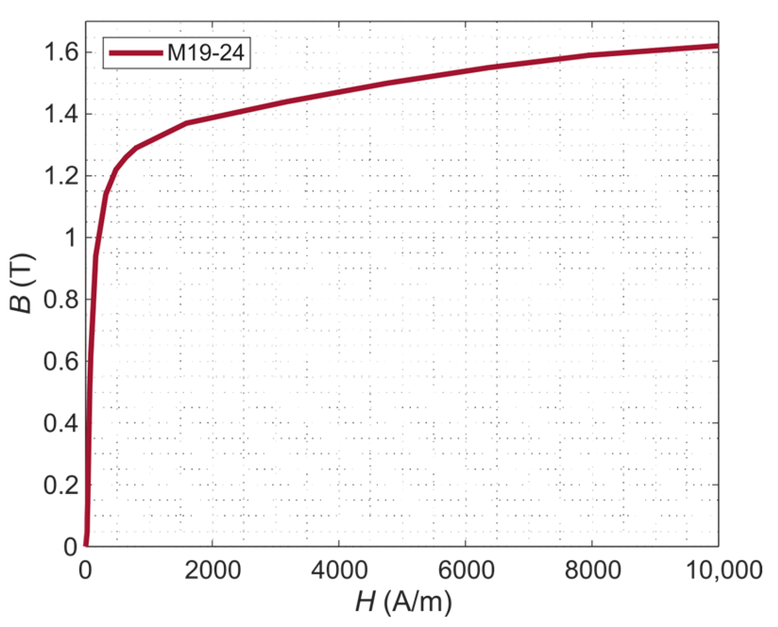
The material properties assigned to both the stator and rotor ferromagnetic region were taken from the Ansys Maxwell library (i.e., M19-24 [
22,
23]). The
B(
H) curve of the material M19-24 is shown in
Figure 3.
The main winding (i.e., stranded coils) and auxiliary winding coils (i.e., solid conductor) were modeled as copper conductors with the bulk conductivity 58 MS/m, while the rotor bars composing the squirrel cage were modeled as aluminum solid conductors having bulk conductivity 23 MS/m. The values of the copper and aluminum conductivities were taken from the Ansys Maxwell material library [
22].
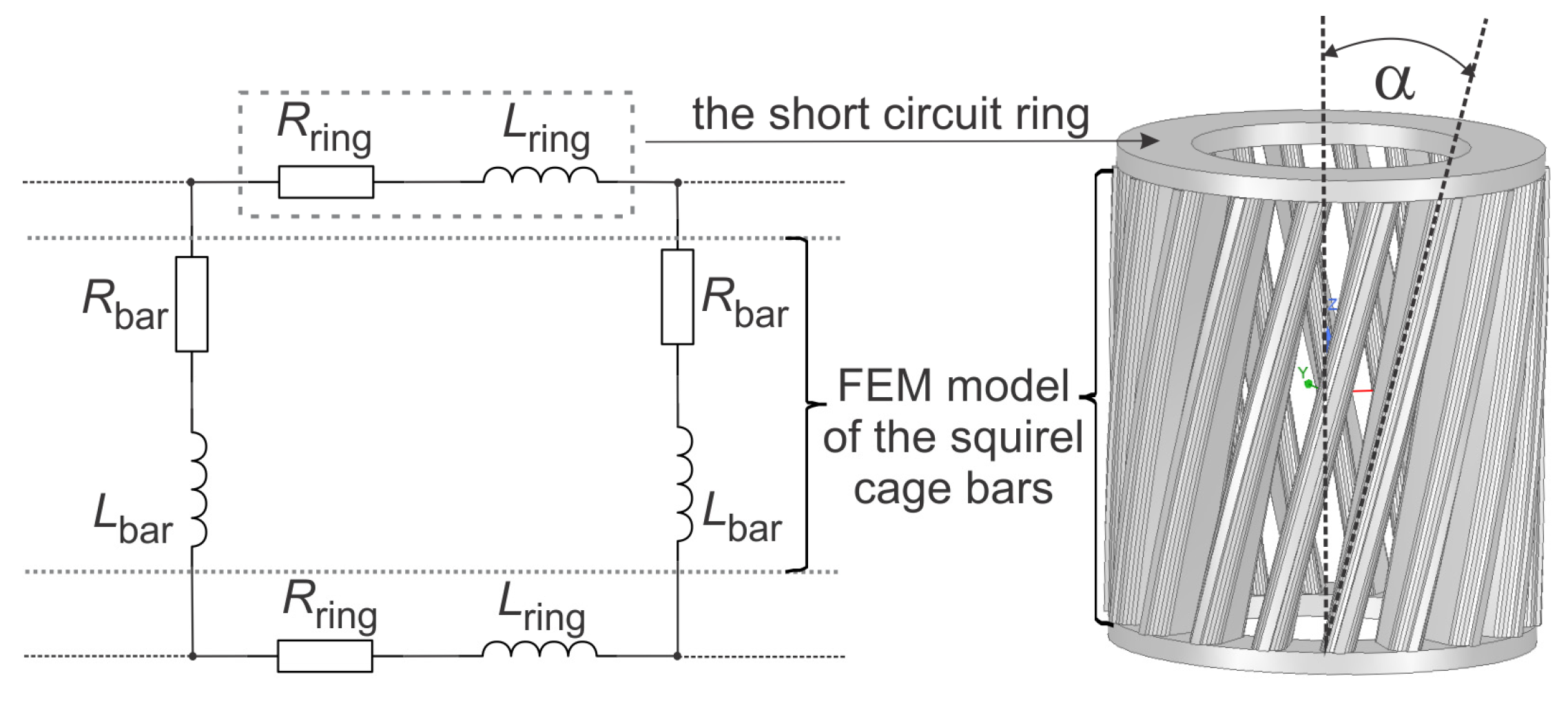
The shape of the 2D numerically modeled squirrel cage rotor bars, which were modeled as solid aluminum conductors, is shown in
Figure 1a. Since the motor was modeled in 2D, the rotor bars in all our models were connected together via an external equivalent circuit composed of the resistance and inductance of the short-circuit squirrel cage ring. The equivalent circuit of the rotor squirrel cage coupled with the 2D finite element model of the motor is shown in
Figure 4, where
Rbar and
Lbar stand for the resistance and inductance of the rotor bars (i.e., active part of the squirrel cage), while
Rring and
Lring stand for a segment of the short circuit ring connecting the adjacent bars (
Figure 4). It should be noted that the auxiliary coils located at the shaded stator poles were also modeled as massive copper conductors and connected together according to the described procedure. The values of the elements
Rbar and
Lbar are automatically calculated with the Ansys Maxwell built-in routine based on the geometrical and material properties of the bar/coil geometry segments, while the elements
Rring and
Lring need to be additionally defined by the user. These values can be analytically calculated by taking into account the geometrical and material properties of the short circuit ring [
2]. The assigned values to the short circuit ring of the squirrel cage were 5 × 10
−6 Ω and 10
−8 H, while the assigned values to the short circuit ring of the shaded coils were 10
−9 Ω and 10
−9 H.
In the first part of this study, we performed the preliminary calculations and showed the influence between the non-skewed (α = 0°) and skewed squirrel cage bars (α = 27 °) on the instantaneous electromagnetic torque
T(
t) and main winding current time profiles
I(t). It should be noted that the α = 27° corresponds to the skewing angle of the real single-phase shaded-pole induction motors [
4]. We have previously investigated the influence of different skewing angles [
4] on the electromagnetic torque ripple. The minimum torque ripple was obtained with α = 27°. [
4] Therefore, in the numerical models we built in this study, the skewing angle was α = 27° with a ten-segment rotor skewing procedure applied [
22] (the length of each segment being 1.4 mm).
In the second part of the study, we focused on the primary objectives of this study and thus investigated the influence of the number and size of the shaded coils (i.e., auxiliary winding) on the resulting torque-speed profiles. In addition, we also calculated and compared the main winding currents versus rotational speed profiles for all three models.
The rotor was rotated via the parametric sweeps procedure by increments of 100 rpm from the no load condition up to 2300 rpm (i.e., 2300 rpm ≤ n ≤ 2999 rpm) and the time-dependent output characteristics such as the instantaneous electromagnetic torque and winding currents have been calculated for each of the imposed angular velocities of the rotor (due to the complex and time-consuming numerical simulations, the computations for n < 2300 rpm were not performed since normally the induction motor does not operate at such high slips). Each working point was calculated for the sinusoidal voltage applied to the main winding, with 230 V at the supply frequency of 50 Hz. For each working point (i.e., rotational speed), the average value of the calculated torque and the rms value of the main winding current have been calculated over the last period of time in the steady state of the signals. In this way, the torque vs. speed T(n) and the main winding current vs. speed profiles I(n) have been determined. In addition, the stand still values of torque and current have also been calculated for the imposed rotor speed n= 0 rpm.
Next, we studied the behavior of the modeled motor at the nominal working point (i.e., 2800 rpm corresponding to the slip 0.06). First, we calculated and compared the distribution of the magnetic flux density for all three models. Second, we calculated the hodographs for each of the analyzed models in order to compare the shape of the resulting elliptic rotational fields and to investigate the influence of the rotating field on the output torque values. We also compared the time profiles of the instantaneous torque for all three models (
Figure 2) to investigate the influence of the number and diameter of the shaded solid coils on the reverse torque contribution to the overall output torque. Namely, the influence of the reverse/breaking torque can also be studied via symmetrical components of the general model and the corresponding equivalent circuit of the motor [
24,
25], based on which the torque of the single-phase induction motor can be expressed as a function of slip
s as follows:
where
RR stands for the resistance of the rotor windings (the resistance of the squirrel cage in our case);
and
are the direct and inverse symmetrical components of the main winding currents, respectively;
is the mechanical angular speed of the rotor; and
s is the slip, which can be easily expressed as
s = (
ns −
n)/
ns (where
ns is the synchronous speed of the rotational magnetic field, and
n is the rotor speed). Subsequently, the shaft power
Pmech can be calculated as a product of the torque and the mechanical angular speed as
From Equation (4), it can be seen that the average torque of the motor is strongly determined by the first term of the equation corresponding to the direct torque
T+ (i.e., the driving motor regime), while the second term of the equation corresponds to the inverse/ breaking torque, which reduces the overall average torque. The second term of Equation (4) also indicates that a more pronounced effect of the short-duration breaking torque occurs at lower slips (due to the term 2-s). However, it is well known that the adverse effects of torque pulsations can be successfully mitigated with an adequate skewing strategy. In addition, the drive moment of inertia also reduces the negative effects of the mechanical vibrations on the motor rotational speed [
1].
Finally, we calculated and compared the amount of copper
mcu required for design of the auxiliary winding for all three models. The main purpose was to compare the amount of copper needed for the design of the shaded coils in the models with one coil and two different diameters to the reference model with two shaded coils. The geometry and dimensions of one coil, taken into account for the calculations of
mcu, are shown in
Figure 5.
We first compared the amount of copper needed for the active part of the coil, meaning that only the segment of the coil belonging to the axial length
L of the coil (i.e., corresponding to the
L of the motor) was taken into account and therefore approximated with Equation (6):
where
ρ is the mass density of the copper (i.e., ρ = 8933 kg/m
3),
Ncoil stands for the number of the shaded coils and
D corresponds to the diameter of the coil (
D =
D1 in case of the reference model—
Figure 2a and the model with one coil with the diameter
D1—
Figure 2b and
D =
D2 in the model with one coil and diameter
D2—
Figure 2c). In this case, the mass of the coil end rings was omitted since they were replaced with the external equivalent circuit given in
Figure 4.
It should be noted that in the case of the shaded-coil motors with shorter axial length
L (which is the case in this study), the end region volume of the shaded coil presents almost half of the total volume of the coil; therefore, it cannot be easily omitted while calculating the
mcu. We therefore also calculated and compared the total mass of the shaded coil (by considering the complete geometry shown in
Figure 5) for all three models. The total mass of the shaded coils is calculated according to Equations (7)–(9), which we derived for the reference model with two coils (
Figure 2a), the model with one coil with
D1 (
Figure 2b) and the model with
D2 (
Figure 2c), respectively.
3. Results and Discussion
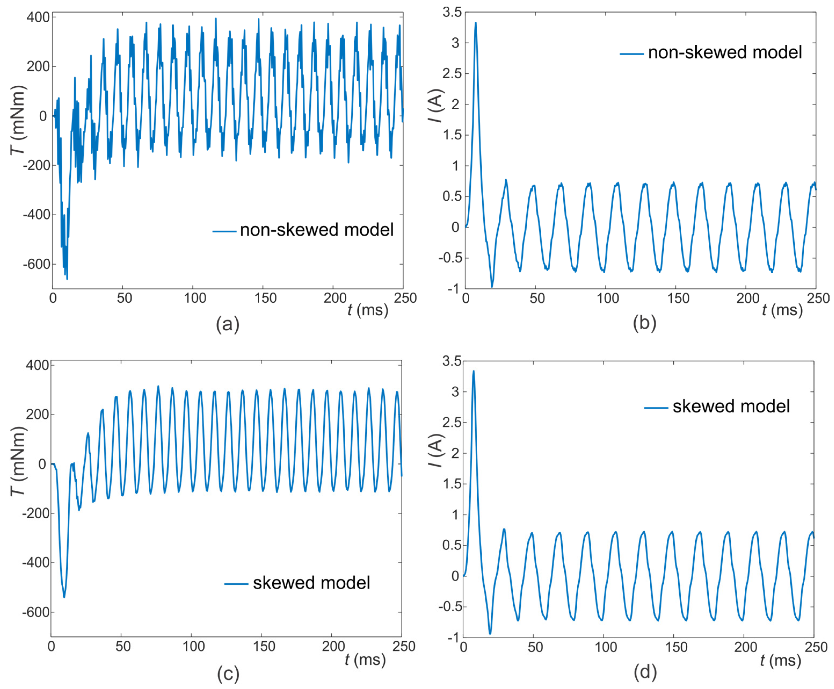
The results of the numerical simulations performed with the 2D numerical model of the reference motor design (
Figure 1) with the non-skewed α = 0° and skewed rotor α = 27° are given in
Figure 6. The instantaneous electromagnetic torque profile and the main winding current time profiles calculated with the model with the non-skewed rotor are shown in
Figure 6a,b, respectively. The torque and current signals obtained from the model with the skewed rotor are shown in
Figure 6c,d.
The results in
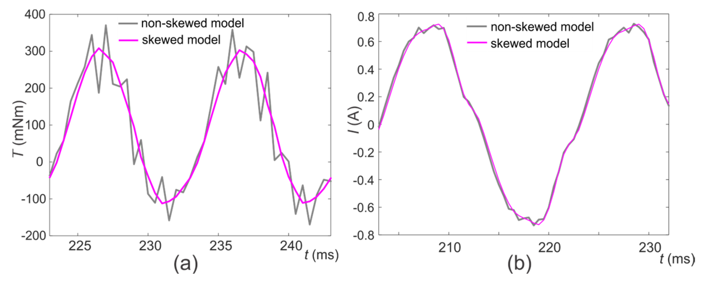
Figure 6 demonstrate and confirm that the ripple present in the electromagnetic torque signal can be efficiently reduced due to the rotor skewing. For a clearer representation of the torque ripple reduction obtained in the model with the skewed rotor α = 27°, with respect to the non-skewed rotor, we visualized and compared the instantaneous torque signals along the last two periods of time (during the equilibrium of the signal after the transient)—
Figure 7a. The comparison demonstrates that the torque ripple present in the instantaneous electromagnetic torque can be significantly reduced with the appropriate rotor skewing. The comparison of the main winding current profiles (
Figure 7b) obtained in the two models (α = 0° vs. α = 27°) also demonstrates that the noise present in the current signal due to the nonlinearities and magnetic saturation can be mitigated with α = 27°.
We further calculated the torque and main winding current versus rotational speed curves (
T(
n) and
I(
n)) for all three studied motor configurations (depicted in
Figure 2), as shown in
Figure 8. We more closely analyzed the behavior of all three models at the nominal working point
n = 2800 rpm (i.e.,
s = 6%) by calculating the magnetic flux density distributions
B(T) and the corresponding hodographs
I(
Iaux) for all three investigated models, as shown in
Figure 9 and
Figure 10, respectively.
Figure 8a shows the comparison of the calculated static torque curves
T(
n) for all three models for the rotational speeds ranging from 2300 rpm <
n < 2999 rpm. The corresponding main winding rms current vs. rotational speed curves
I(
n) for all three models for the same rotational speed range are shown in
Figure 8b.
The results shown in
Figure 8a show that the linear part of the
T(
n) curves from 2999 rpm up to 2800 rpm (indicating the operating region of the modeled motor) are almost identical for the reference model and the model with one shaded coil with the diameter
D1. Namely, the calculated values of the torque at the nominal point (
n = 2800 rpm, s = 6%) were
T = 83.8 mNm and
T = 82.8 mNm for the reference model and the model with one coil with
D1, respectively (the corresponding shaft powers are
Pmeh = 24.6 W and 24.3 W). This means that the reduction in the number of coils does not significantly affect the torque at the nominal working point of the motor modeled in this study. However, the slope of the linear part of the
T(
n) curve is reduced with the increase in the shaded-coil diameter (from
D1 to
D2). In this case, the value of the nominal torque is reduced to
T = 65.16 mNm (the shaft power in this case decreases to
Pmeh = 19.1 W). The current versus rotational speed
I(
n) curves given in
Figure 8b show that the model of the reference motor design is characterized with somewhat higher main winding current compared to the model with one shaded coil with
D1 (i.e., at the nominal slip the rms value is
I = 0.5 A—the reference design versus
I = 0.46 A—design with one shaded coil with
D1). The highest currents are obtained with the motor design with only one shaded coil and the larger diameter
D2 (i.e., the rms value
I = 0.53 at the nominal slip)
. Therefore, the increase in the coil diameter degrades the motor performance since a higher main winding current in the linear operating range of the motor also results in lower motor efficiency.
The results in
Figure 8a also indicate that the maximum torque can be found within the range from 2500 rpm to 2600 rpm and that the highest maximum torque can further be achieved with the reference model having two shaded coils. The maximum torque further decreases with the decrease in the number of coils and increase in the coil diameter. The higher torque-speed characteristics and higher current in the reference model can be attributed to the higher magnetic flux density
B(T) in the rotor compared to the model with only one shaded coil with the same diameter
D1, as shown in
Figure 9a,b, respectively. However, if the diameter of the shaded coil is increased to
D2, the magnetic flux density
B(T) within the rotor remains almost equal to the
B(T) obtained in the model with
D1.
It should be noted that magnetic flux density
B(T) (
Figure 9) is displayed for the time increment
t = 248 ms at which the maximum value of both
B(T) and the main winding current
I(t) has been obtained (i.e., the signal observed at the last period of time).
From
Figure 9, it can be observed that the
B(T) in the rotor of the model with two shaded coils per pole reaches a higher
B(T) compared to the models with only one shaded coil (due to the higher number of ampere-turns present on the shaded pole of the reference model compared to the remaining two models). A higher value of ampere-turns also leads to a more pronounced shift of the magnetic field from the shaded-pole area towards the magnetically unsaturated part of the stator and further into the rotor. Such an influence of the ampere-turns has a direct impact on the torque-speed characteristic and subsequently on the main winding current versus speed characteristic. It can also be observed that the stator core is locally saturated (i.e., the knee value of the stator core
B(
H) is reached—
Figure 3) in all models within the near proximity of the air gap extension. The effect of the local saturation improves the rotating magnetic field in the air gap, which in turn facilitates the start of the motor [
9,
10,
11,
12]. The latter yields higher main winding current and also a higher value of the starting torque. Namely, the starting torque
Tstart is directly proportional to the main winding current, the auxiliary current and the phase shift between them [
24].
Based on the calculated currents in the main and auxiliary windings, we can plot a hodograph (
Figure 10), which represents the relationship of currents
I(
Iaux).
Figure 10 depicts the resulting hodograph
I(
Iaux) calculated at the nominal working point (i.e.,
n = 2800 rpm) during the last period of the observed current signals. A similar relationship of
I(
Iaux) can be observed at other working points, with the highest value of the currents expected under the starting condition (i.e.,
n = 0 rpm). The hodographs at
n = 0 rpm should also contain the transient dynamics of the starting/inrush currents. In order to precisely demonstrate and compute the transients, the mechanical transient behavior (by taking into account damping and moment of inertia) should also be considered and the 3D numerical models used to precisely address the local inhomogeneity and saturations, which reflect in the transients of the starting/inrush current. The hodographs indirectly illustrate the rotating field profile that is created in the air gap between the rotor and stator with a specific motor design (i.e., number and diameter of the shaded coils) [
2].
As demonstrated in
Figure 10, the main winding current is, as expected, significantly smaller than the current obtained in the auxiliary windings. Such difference in currents occurs due to the larger number of the main winding turns (which was kept constant in all three models:
N = 2560) with respect to the number of shaded coils/turns forming the auxiliary winding (i.e.,
N = 2 in the reference model (
Figure 2a) and
N = 1 in the models with the shaded-coil designs shown in
Figure 2b,c). The comparison of the calculated hodographs confirms that the model with two shaded coils provides a wider and thus stronger rotating field compared to the rotating field obtained with one shaded coil and equal diameter
D1. The larger diameter of the shaded coil further enhances the rotational field, which subsequently increases the starting torque. However, at the nominal working region of the motor, such a design increases the contribution of the inverse/breaking torque and thus decreases the overall average torque. The obtained shape of the hodographs (
Figure 10) is in agreement with the rotating field shape/profile expected in all single-phase shaded-pole induction motors [
2] (it is rather elliptical and far from the circular one that is typical for three-phase induction motors). Also, the elliptical shape of the field in the model with one short-circuited ring of the auxiliary winding is even more significantly distorted due to the saturation of the ferromagnetic core and the influence of the rotor back on the stator. However, this form of the rotating field is sufficient for the motor to develop and maintain the torque [
2]. As stated before, the undesirable effects of noise and vibration due to the non-uniform rotating field can be minimized by an adequate skewing angle [
1].
We further investigated the influence of the number and size of the shaded coils on the starting torque at 0 rpm. The calculated starting torques
Tstart are shown in
Figure 11. The results show that the model with two shaded coils develops a higher starting torque
Tstart = 33 mNm due to the presence of a stronger rotating field compared to the model with the same design but one shaded coil (i.e.,
Tstart = 14.3 mNm), as also demonstrated via the corresponding hodographs given in
Figure 10. Based on this, we can conclude that if a large starting torque is not required (e.g., in many home appliances), a motor with a single shaded coil could be used without reducing the torque at the nominal operating point. However, if the starting torque is necessary, two shaded coils per stator pole can provide two times higher value of the starting torque compared to the single coil design. The starting torque can be increased, with the shaded coil having a larger diameter, due to the higher winding current and thus stronger/wider rotating field, as also demonstrated with the corresponding hodograph (
Figure 10). Namely, the starting torque obtained with the design with
D2 was
Tstart = 18.2 mNm. However, our results demonstrate that such a design does not contribute to better performance at the nominal operating point of the motor (
Figure 8 and
Table 1).
The instantaneous torque profiles calculated for all three models at nominal rotational speed
n = 2800 rpm are visualized and compared in
Figure 12. The contribution of the short-duration breaking torque/inverse is depicted with the negative values of the torque. The calculated torque values are further evaluated and compared by calculation of the peak-to-peak
Tpp values and the maximum
Tmax and minimum
Tmin values and compared to the final overall average value
Tavg. The obtained results are summarized in
Table 1. The results demonstrate that the highest
Tpp values were, as expected, obtained with the reference model, which subsequently results in the highest average value compared to the models with one shaded coil. The smallest peak-to-peak value
Tpp was found in the model with one shaded coil with diameter
D1; however, this model outperforms the design of the motor with the larger diameter
D2 since the larger diameter results in a higher value of the breaking torque, which consequently reduces its average value
Tavg (
Table 1). The value of the breaking torque can be further reduced by modifying the geometrical and material properties of the rotor winding (i.e., squirrel cage).
The calculated nominal torque and the corresponding amount of copper needed for the design of the auxiliary winding/shaded coils in all three models are given in
Figure 13. Both the nominal torque and the coil mass are normalized to the values of torque and mass calculated for the reference model. The results show that a smaller amount of copper is needed for the design of the motor, with one shaded coil for almost the same torque achieved at the nominal working point. However, the single shaded-coil design provides lower starting torque as opposed to the starting torque achieved with the reference model. The results also indicate that the larger shaded-coil diameter decreases the nominal torque; moreover, it requires a larger amount of copper for the design of the auxiliary winding (
Figure 13). In this regard, the design of the motor with one shaded coil and smaller diameter provides better design properties. We can therefore conclude that the amount of copper can be reduced by 53.8% compared to the reference model with two shaded coils, leading to the more cost-effective design of the shaded-pole motors used in applications that do not require a high starting torque.
All the obtained results with all three models/motor designs are summarized and compared in
Table 1. The calculated values given in the table are peak-to-peak value
Tpp, maximum value
Tmax, minimum value
Tmin and the average torque corresponding to the nominal torque at the nominal slip s = 6%, the calculated nominal power
Pn, nominal current
In, the starting torque (i.e., at standstill
s = 1) and the calculated mass of copper needed for the design of the auxiliary winding.
4. Conclusions
In this paper, a finite element-based model of a reluctance-enhanced single-phase shaded-pole induction motor with a C-frame stator core has been built, and the numerical simulations have been performed in transient magnetic analysis in 2D. Within the first part of the study, we analyzed the influence of the skewing angle of the rotor bars on the instantaneous electromagnetic torque profile and the stator main winding current profile of the reference model of the motor (i.e., the motor with two auxiliary coils). The obtained numerical results indicate that the rotor bar skewing angle has a significant influence on the torque and current signal. The pronounced torque pulsations observed at zero skewing angle α = 0° were significantly reduced with the skewing angle α = 27°.
Second, we investigated the influence of number and size of the auxiliary shaded coils on the output torque speed characteristics of the modeled motor. The results show that the reference model with two shaded coils develops, as expected, a higher starting torque compared to the motor with only one shaded coil, having the same dimensions as the coils of the reference model. However, the operating range of the motor (i.e., the linear part of the torque speed curve in the near proximity of the nominal slip) with only one shaded coil provided almost the same value of the torque as the reference motor (with two shaded coils). These findings indicate that if a given application does not require a large starting torque (e.g., low-power fans), a shaded-pole motor with a single auxiliary shaded coil could be used without reducing the nominal torque (i.e., the torque values within the linear operating area).
We further investigated the influence of the shaded-coil diameter on the output torque and stator current characteristics. Namely, we compared the results calculated with two models having one shaded auxiliary coil with different coil diameters (D1 = 2.4 mm and D2 = 3.4 mm). The results show that the motor with the single shaded coil with a larger diameter provided a higher value of the starting torque (comparable to the reference model having two shaded auxiliary coils) compared to the starting torque obtained with the smaller shaded-coil diameter. The higher starting torque in the model with D2 was obtained due to the higher main winding current, which was also reflected in a wider hodograph compared to the model with D1. However, the lower torque speed characteristic has been obtained with the model having larger coil diameter D2 due to the presence of the highest value of the braking/spinning torque, which reduced the mean torque value. In addition, the higher obtained value of the main winding current would also contribute to the lower efficiency of this motor configuration. Therefore, based on these results, we can conclude that the single shaded-coil motor with the smaller coil diameter D1 outperformed the motor with D2 analyzed in this study. The obtained results also indicate that the coil diameter should be carefully selected and optimized in order to obtain the desired motor performance/properties.
Based on the results obtained in this paper, we demonstrated that the amount of material used (i.e., copper) and the number of components (only one auxiliary coil instead of two) can be successfully reduced based on prior precise analysis of geometrical and material parameters of the motor configuration, which can be efficiently adapted to each individual application requirements via numerical modeling and analysis. These results can be important in simplifying the manufacturing process, reducing the material and number of components and subsequently resulting in a lower price of the final product. Future research work will be focused on the analysis and prediction of these processes by means of developing the motor digital twins. Further improvements in the numerical model can be made by modeling the motor geometry in 3D by also taking into account the leakage inductances of the main winding, the squirrel cage end ring and the mechanical transient simulations to more precisely simulate the dynamic torque and starting current signal calculation. Future research directions will also involve optimization procedures of the geometric, magnetic and electric properties of the motor based on multi-objective and genetic algorithm optimization techniques.


