1. Introduction
A current research problem in the field of robotics is the development of systems capable of interacting with humans in a safe and natural manner. The use of variable stiffness actuators (VSAs) and series elastic actuators (SEAs) is part of the solution that has been found. The incorporation of this type of actuator into robot design produces versatile and adaptable systems, especially in dynamic environments, and facilitates physical interaction with the use [
1]. This technological advancement is particularly relevant in the field of motor training and rehabilitation devices, which aim to improve the functionality and quality of life of users [
2].
Specifically, upper-limb motor rehabilitation plays a crucial role in the recovery from various neuromuscular conditions in infants. In this context, it is essential that the robotic assistive devices used during therapies have characteristics that guarantee safe and comfortable interaction, minimizing the risks associated with involuntary user movements and adapting to their changing capabilities. Reducing mechanical impedance and improving safety in the face of unexpected contacts are the main advantages offered by an SEA [
1], which are indispensable characteristics in devices used for training and motor rehabilitation assistance in children, whose musculature and joints are still developing [
3].
Additionally, the control strategy implemented in this system includes a derivative gain, , in the feedback loop, which acts as virtual damping. This term compensates for oscillations caused by the elastic behavior of the SEA, further enhancing the system’s dynamic stability. Combined with the inherent damping of the actuator and the viscoelastic properties of the user’s limb during physical contact, this solution ensures safe and smooth operation without requiring additional damping elements or active impedance control.
An SEA incorporates an elastic element (spring) between the rigid actuator and the load, which provides the system with compliance—the ability to deform in a controlled manner under external forces—and backdrivability, allowing the user to passively move the mechanism without encountering excessive stiffness [
4]. The authors of [
2] report the results of controlled tests to validate these characteristics, measuring up to 60% reductions in peak transmitted forces during sudden collisions when a properly dimensioned SEA is integrated into an upper-limb rehabilitation device with hybrid control.
Few systems using SEAs for upper-limb rehabilitation are found in the literature. In [
1], the authors implement a robot driven by series elastic actuators (SEAs) for this task. The force feedback from the human–robot interaction is measured on the user, and the intensity of robotic assistance is periodically adjusted based on the interaction evaluation results. The system demonstrated, through experimentation with a healthy adult user, increased safety in human–robot interaction by integrating intention-assisted control based on the use of SEAs. However, its design did not address anthropometric compatibility for use in pediatric populations.
Research such as that presented in [
5] proposes combining SEAs with robust control strategies to ensure safety and compliance in human–robot interaction in closed-loop control. A customized SEA is developed, but its validation does not involve functional training tasks or applications in the area of motor rehabilitation.
In other studies, spring deformation is used as an indirect interaction sensor, eliminating the need for external load cells or other sensors. In [
6], the authors used SEAs together with accelerometers embedded in an exoskeleton as indirect force sensors for intention detection and to control movement routines. Its application was restricted to multi-link structures; therefore, this type of rehabilitation device is not easily adaptable to pediatric populations.
Although several exoskeletons and end-effector devices for upper-limb training exist, as reported in [
7], most are designed for youth and adult populations, making them difficult to adjust for users in the preschool stage. However, clinical evidence indicates that early interventions (ages 2–5) significantly improve motor development and neuromuscular plasticity in movement disorders [
8].
An analysis of reported works in the literature that incorporate SEAs revealed two limitations for the development of pediatric upper-limb motor rehabilitation devices: (i) the complexity of multi-link exoskeletons, which requires strict joint alignment, and (ii) the scarcity of validations focused on pediatric populations or adapted to specific functional trajectories [
7].
For the first case, an alternative in the design of such rehabilitation systems consists of using end-effector-type devices, which concentrate interaction at the wrist and reduce alignment requirements [
9]. However, in a recent review presented in [
10], the authors highlight the lack of such devices that are adaptable and safe for children under five years old.
In the second case, there are few works that document the integration of SEAs in planar architectures and their performance against disturbances through experimental validation. Recently, results published in [
11] report the experimental validation of the kinematic and dynamic model of a 3DOF VSL manipulator, which improves the efficiency and accuracy of VSL manipulators while ensuring safe human–robot interaction in various industrial applications.
In [
12], a previous work by the authors, the essential properties and characteristics required in training or rehabilitation devices were presented to allow for mechanical impedance decoupling, with the aim of improving the intrinsic safety of actuation systems. To achieve these characteristics, a variable stiffness actuator configuration was designed, and its model was experimentally validated using low-level active control. Similar SEA concepts have been successfully explored for safe physical interaction in human–robot interfaces [
13], reinforcing the relevance of this architecture. Based on that design, this paper presents the design, modeling, and validation of a two-degree-of-freedom end-effector-type robotic device for upper-limb training in children aged 2 to 5 years, operating in the horizontal plane. It incorporates series elastic actuators (SEAs) with dual springs at each joint, allowing decoupling of the rigid actuator’s mechanical impedance and imparting the system with compliance and backdrivability properties. This stage is limited to laboratory experimental validation of the functional prototype, leaving system evaluation with users for future work.
Although impedance control is a well-established strategy to regulate both stiffness and damping in physical human–robot interaction [
14], it typically requires accurate dynamic modeling and high control bandwidth. In this work, a different approach is adopted: by using dual-spring SEA modules, mechanical compliance is introduced passively, without requiring active stiffness modulation. As discussed in [
14], passive compliance combined with sufficient intrinsic damping from the actuator is often adequate to ensure safety in interaction tasks. This design choice simplifies the control implementation and avoids resonance phenomena during pediatric motor training exercises, while maintaining safe and adaptive behavior.
The main contribution of this work is the design of a rehabilitation system for the upper limb, featuring simple architecture, passive safety, and appropriate dimensioning for the preschool stage. The system can decouple the mechanical impedance of the rigid actuator from the load while integrating passive absorption of external disturbances, ensuring its suitability for pediatric applications.
Unlike existing approaches that either target adult populations or rely on complex multi-link exoskeletons, this work introduces a planar end-effector-type robotic system specifically dimensioned and validated for children aged 2 to 5 years. To our knowledge, it is the first implementation of dual-spring SEA modules in a pediatric-oriented training device, validated through dynamic modeling, control simulations, and experimental tests that include both active and passive interaction scenarios. This novel combination of architecture, control, and safety mechanisms addresses key limitations identified in previous studies and establishes a replicable foundation for compliant pediatric training systems.
The paper is organized as follows.
Section 2 presents the design of the SEA, the structure of the end-effectors, the dynamic model, the control design, and the implementation.
Section 3 presents the experimental protocol and discusses the experimental results. Finally,
Section 4 presents the conclusions.
2. Materials and Methods
Using variable stiffness actuators in robotic devices for upper-limb training and rehabilitation makes it possible to perform different types of therapy—assistive, corrective, and resistive—with a single system, simply by adjusting the actuator’s stiffness. One of the key advantages is that, regardless of the routine, the elastic element can decouple the motor’s mechanical impedance from the load whenever necessary, improving the safety of user–device interaction.
This section builds upon the SEA design presented in [
12], now integrated into a two-degree-of-freedom end-effector mechanism suitable for upper-limb training and rehabilitation tasks in children aged 2 to 5 years. We describe the mechanical synthesis based on pediatric anthropometric parameters, the dynamic model including interaction with the upper limb, a computed torque controller with integral action, and the implementation of a prototype validated experimentally under lab conditions.
2.1. Series Elastic Actuators (SEAs)
A compliant actuator allows deviations from its equilibrium position depending on the external force applied. The equilibrium position of an adaptive actuator is defined as the point at which it produces zero force or torque. Variable stiffness actuators include an elastic component that connects the rigid actuator to the load. This feature allows for tuning of the actuator’s intrinsic stiffness, which enhances dynamic performance. Moreover, the elastic element in these actuators helps decouple the mechanical impedance of the rigid actuator from the load, improving safety when responding to external forces or disturbances [
15].
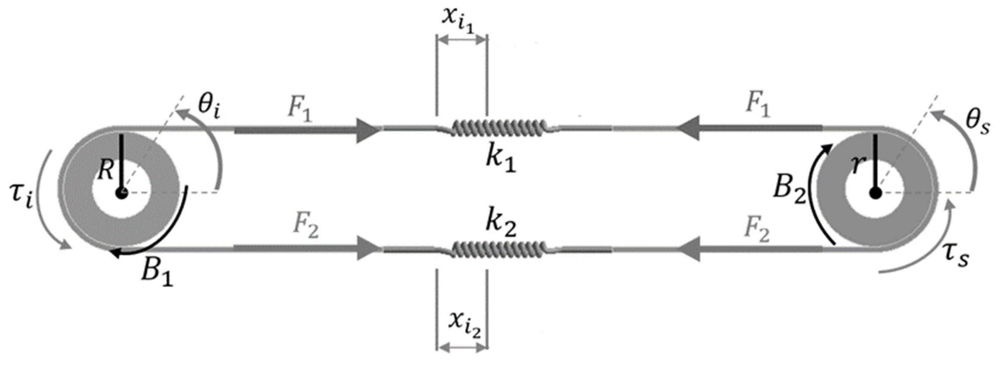
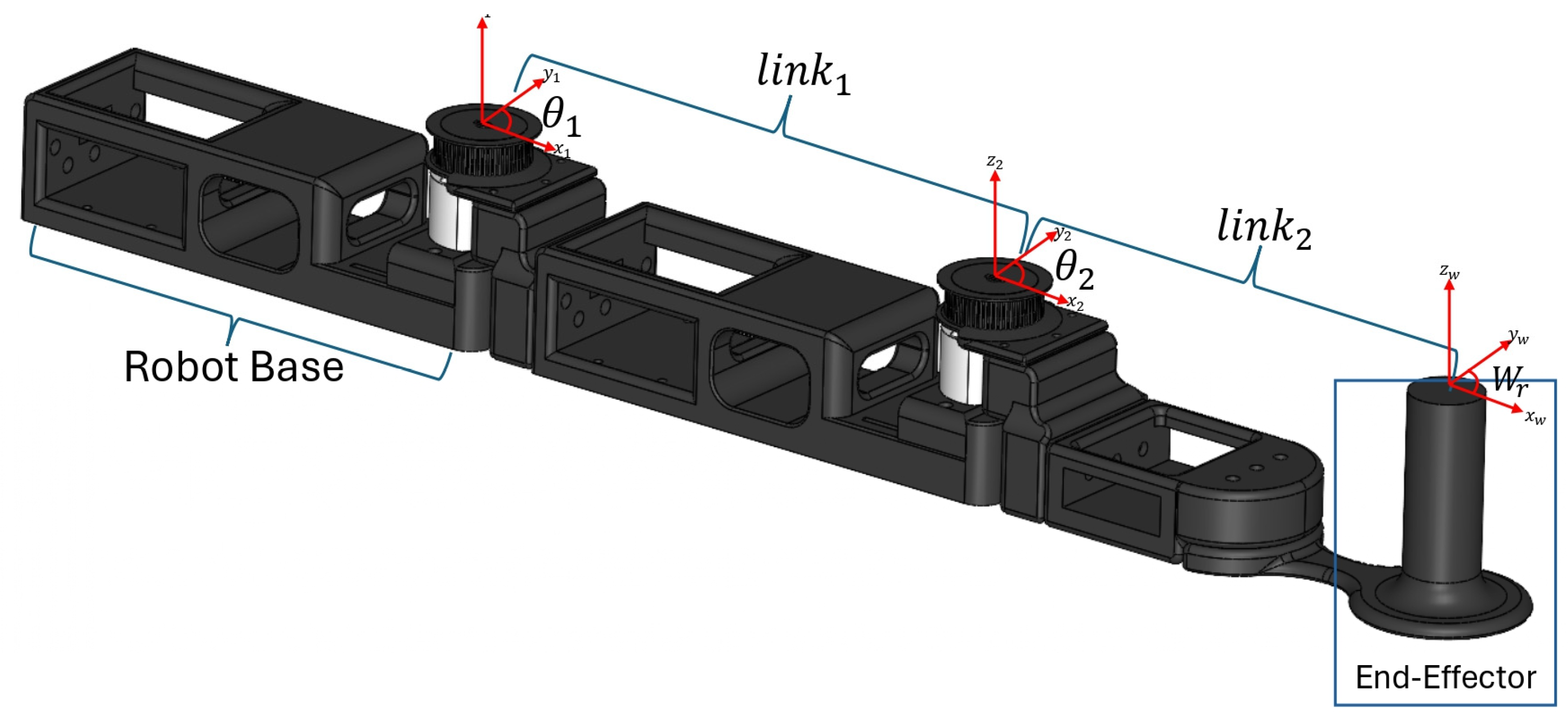
For the implementation of the pediatric upper-limb rehabilitation system—designed as an end-effector type—we selected an SEA architecture featuring two elastic elements in an antagonistic configuration, as shown in
Figure 1 [
12]. This SEA is composed of two springs connected in series. The system is defined by the input torque
, input and output pulley radii
and
, angles
and
, spring constants
and
, spring deformations
and
, output torque
, and viscous damping terms
and
.
When two springs are arranged antagonistically, as shown in
Figure 1, the equivalent stiffness constant of the system is defined as the sum of the individual spring constants, as described by Equation (1).
2.1.1. Kinematic–Torque Relationship of the SEA
The linear deformation experienced by the springs in the SEA, shown in
Figure 1, is modeled as presented in Equation (2):
Applying Hooke’s law, the generated force is evaluated using Equation (3):
The output torque transmitted through the mechanism is then calculated as shown in Equation (4):
By rearranging the terms, the torsional model is obtained and described in Equation (5):
Additionally, the relationship between input and output positions can also be expressed as in Equation (6):
When considering the dynamic effects of both motor and load, the full system behavior is described by Equations (7) and (8):
where
and
represent the inertias of the motor and load, respectively, and
stands for external torques acting on the output.
In the Laplace domain, and assuming
, the dynamic model can be represented by Equations (9) and (10). From these, the transfer function between the input torque and output position is derived as Equation (11).
To validate the model described by Equation (11), a simulation-based experiment was carried out using the parameters listed in
Table 1. A sinusoidal excitation signal was applied in MATLAB
® 2024a on a computer equipped with an Intel(R) Core(TM) i5-9300H CPU @ 2.40 GHz and 16 GB of RAM.
Figure 2 shows the system’s response under ideal conditions, i.e., without any external interaction. In subplot (b), the output position
closely follows the input
shown in subplot (a). During the same time interval, subplot (c) reveals minimal spring deformation, indicating high stiffness and low excitation frequency.
In a second simulation experiment, the SEA was evaluated under non-ideal conditions, specifically, with static friction at the output shaft.
Figure 3 presents the results, showing that, even with motor motion (subplot a), the output position (subplot b) remains constant. Meanwhile, significant spring deformation occurs (subplot c), generating an elastic force profile (subplot d) that corresponds to the sinusoidal input torque.
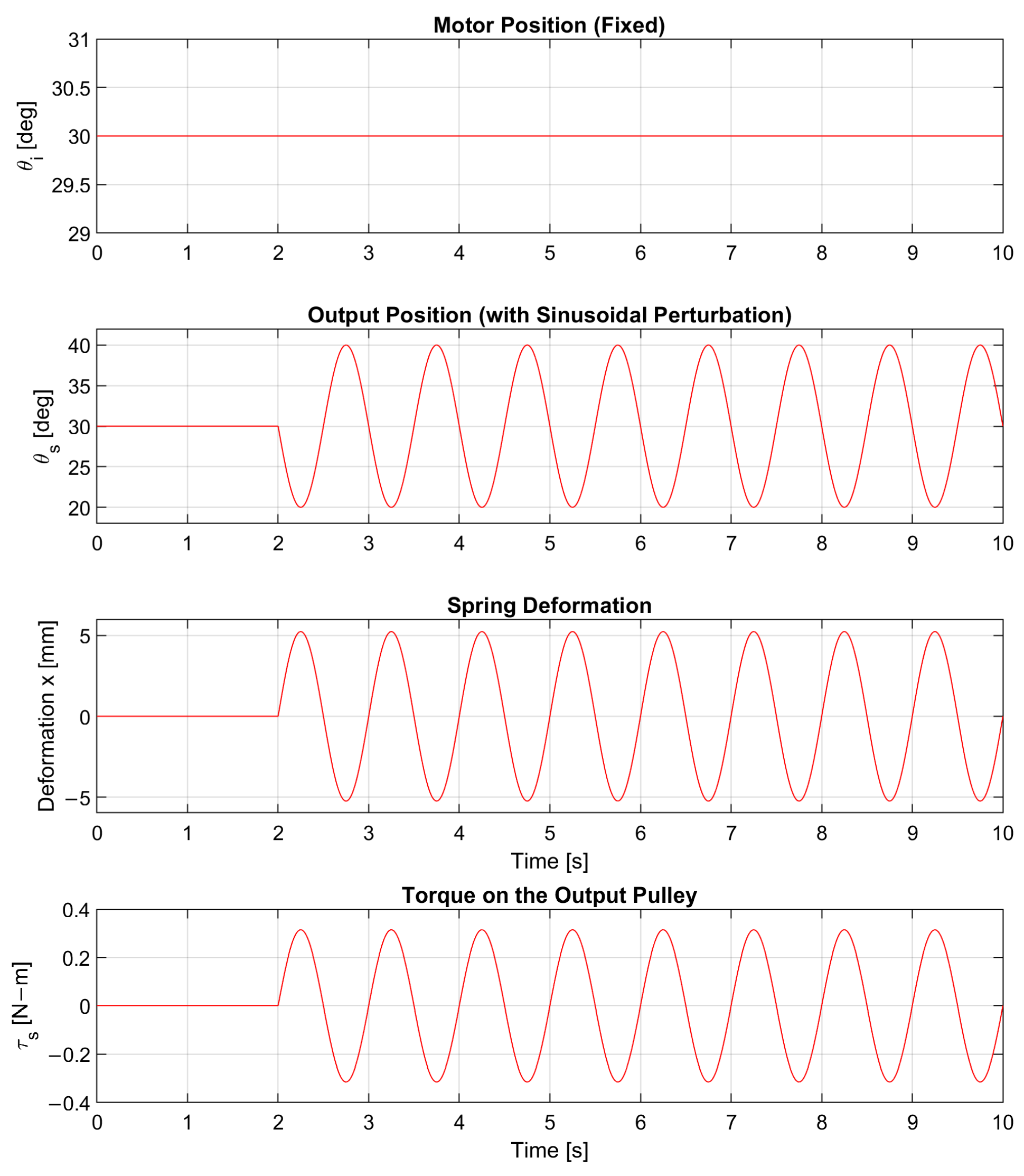
In the third experiment, the system was tested against an external disturbance applied directly to the output shaft while the motor position remained fixed. This scenario helps evaluate the spring’s capacity to absorb loads and decouple the actuator input from the load. As shown in
Figure 4, the motor maintains a fixed position, yet the spring deformation signal (subplot c) follows the external disturbance applied to the output (subplot b).
The observed behavior across all simulation experiments confirms that the modeled SEA exhibits both compliance and backdrivability. On the one hand, progressive spring deformation in response to external excitations demonstrates that the system is mechanically flexible, capable of softening interaction forces and protecting the actuator. On the other hand, the ability of the load to move the output while the motor remains still validates the backdrivable nature of the design, confirming that the system can be driven from output to input without rigid opposition.
While the dynamic model and simulations presented focus on stiffness and backdrivability, it is important to note that the dual-spring configuration and the internal friction of the actuator (including both mechanical and electronic damping) passively contribute to the overall stability of the system. Moreover, since the device is intended for direct physical interaction with users, the human limb itself introduces viscoelastic properties that act as an additional damping source. These characteristics, inherent to the SEA design, effectively attenuate potential oscillatory behavior without the need for external damping mechanisms or active impedance control. No signs of resonant behavior were observed under any of the tested scenarios, reinforcing the suitability of the proposed configuration for safe physical interaction during training tasks.
2.1.2. Design and Fabrication of the Elastic Element
Once the mathematical model obtained from the structure shown in
Figure 1 was validated, the mechanical design and fabrication process of the elastic element were carried out. The stiffness value determined for each actuator was 1000 N/m. Accordingly, a helical compression spring was designed and manufactured using ASTM A228 piano wire sourced in Mexico City, Mexico. This high-carbon steel provides a stable shear modulus (G) and high fatigue resistance, both essential properties for repetitive-use applications in rehabilitation [
16].
This stiffness value was selected to satisfy two essential design requirements: first, it must transmit sufficient torque to move the pediatric upper limb; second, it must allow deformation when unexpected external forces are applied, ensuring passive safety. According to the literature, the average body weight of children aged 2 to 5 years is approximately 17.9 ± 3.7 kg [
17]. Assuming the upper limb represents around 5% of body mass [
18], the estimated limb mass ranges between 0.6 kg and 1.0 kg.
To be conservative, a worst-case limb mass of 1.2 kg was considered. The gravitational force acting on this mass is calculated by multiplying the mass by gravitational acceleration, giving approximately 11.76 N. This force is assumed to act through a moment arm of 3 cm (i.e., 0.03 m), representing the typical pulley or linkage radius in the system. The resulting torque requirement is around 0.353 Nm.
Applying a factor of safety of 4 to this nominal torque yields a design torque of approximately 1.41 Nm. To ensure this torque can be delivered without exceeding safe deformation limits, a maximum allowable spring deflection of 4 mm (i.e., 0.006 m) was established. Dividing the required force by the allowed displacement yields a minimum required stiffness of about 2000 Nm for the entire actuator system. Since the SEA uses two springs in series with additive stiffness, each spring would need to provide around 1000 Nm.
Nevertheless, a stiffness value of 1000 N/m per spring was chosen to provide a balance between performance, manufacturability, and mechanical robustness. This value ensures sufficient torque transmission, limits deformation to safe levels, and preserves the system’s compliance and backdrivability. Altogether, this configuration supports the safety and adaptability goals of the proposed training device for pediatric users.
The stiffness of a cylindrical compression spring is calculated using Equation (12), as reported in [
16]. Here,
represents the wire diameter,
the coil diameter, and
the number of active coils.
Using the parameters listed in
Table 2, the resulting mean diameter of the spring is calculated from Equation (13),
Each spring is housed inside a threaded sleeve that allows for preload adjustments of up to ±10% of the nominal stiffness value. This feature helps compensate for manufacturing tolerances and fine tune the overall compliance of the SEA for different therapy protocols. Additionally, it ensures that the maximum spring deformation under a peak torque of remains below the elastic limit of the material.
With this design, the SEA provides the necessary stiffness to transmit the required torque without sacrificing mechanical flexibility. This balance is particularly crucial for the proposed training device, which must deliver adequate force while remaining compliant and safe for pediatric use.
2.2. Design of the End-Effector-Type Training Device
Upper-limb motor rehabilitation plays a fundamental role in the recovery of various neuromuscular conditions. Support devices used for this purpose are typically classified into end-effectors, exoskeletons, and exosuits and generally operate in three main training modes: corrective, resistive, and assistive [
2].
A key feature in such devices must be their ability to ensure safe and precise interaction, especially when designed for pediatric users. This includes minimizing risks associated with involuntary movements and adapting to each user’s changing physical capabilities. Studies like the one presented in [
9] have shown that end-effector architectures offer greater tolerance to morphological variability and reduce excessive stiffness, which are often associated with multi-link exoskeletons. These configurations are thus particularly suitable when comfort and safety are priorities. In addition, end-effector structures simplify mechanical complexity and help mitigate alignment issues inherent in exoskeletons.
Another important point is that an end-effector layout facilitates the integration of series elastic actuators (SEAs) in each joint. This adds compliance and backdrivability to the system without compromising its functional workspace.
Considering all the above, the proposed device adopts a planar end-effector configuration with two degrees of freedom (DOF), using SEAs and placing the point of interaction at the user’s wrist. This configuration allows the arm to follow predefined trajectories without requiring strict joint alignment, simplifying setup, improving adaptability, and reducing anthropometric mismatches in children under 5 years old [
10].
In order to reproduce functional tasks such as reaching, pushing, or pulling—typical of daily living activities targeted during pediatric training and rehabilitation—the mechanism must cover basic joint combinations of shoulder flexion-extension, shoulder abduction-adduction, and elbow flexion-extension [
19], even though the movement is restricted to a horizontal plane.
2.2.1. Wrist Workspace of the Upper Limb
To compute the workspace, we used joint range data and anthropometric measurements from children aged 2 to 5 years. These include an elbow range between 11 and 148°, shoulder flexion from −30° to 180°, and ±90° in abduction [
20,
21]. Regional studies report combined upper-arm and forearm lengths ranging from 33 to 40 cm in five-year-old children [
18,
22].
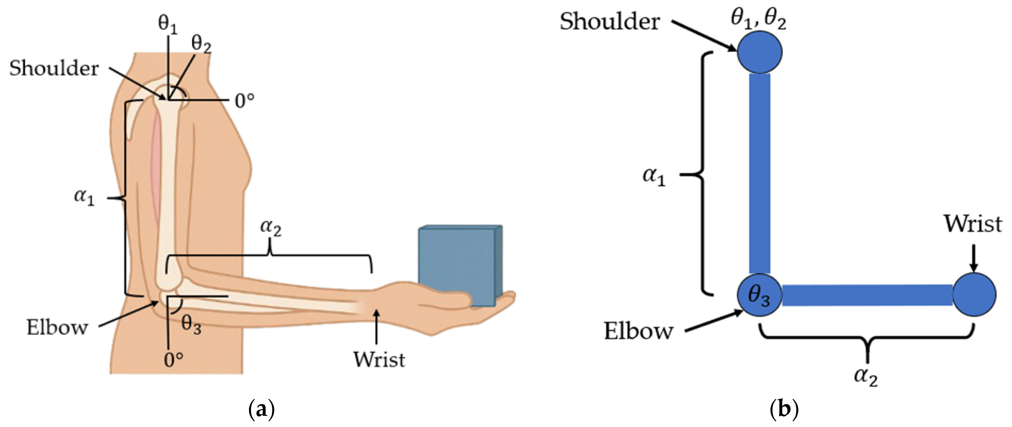
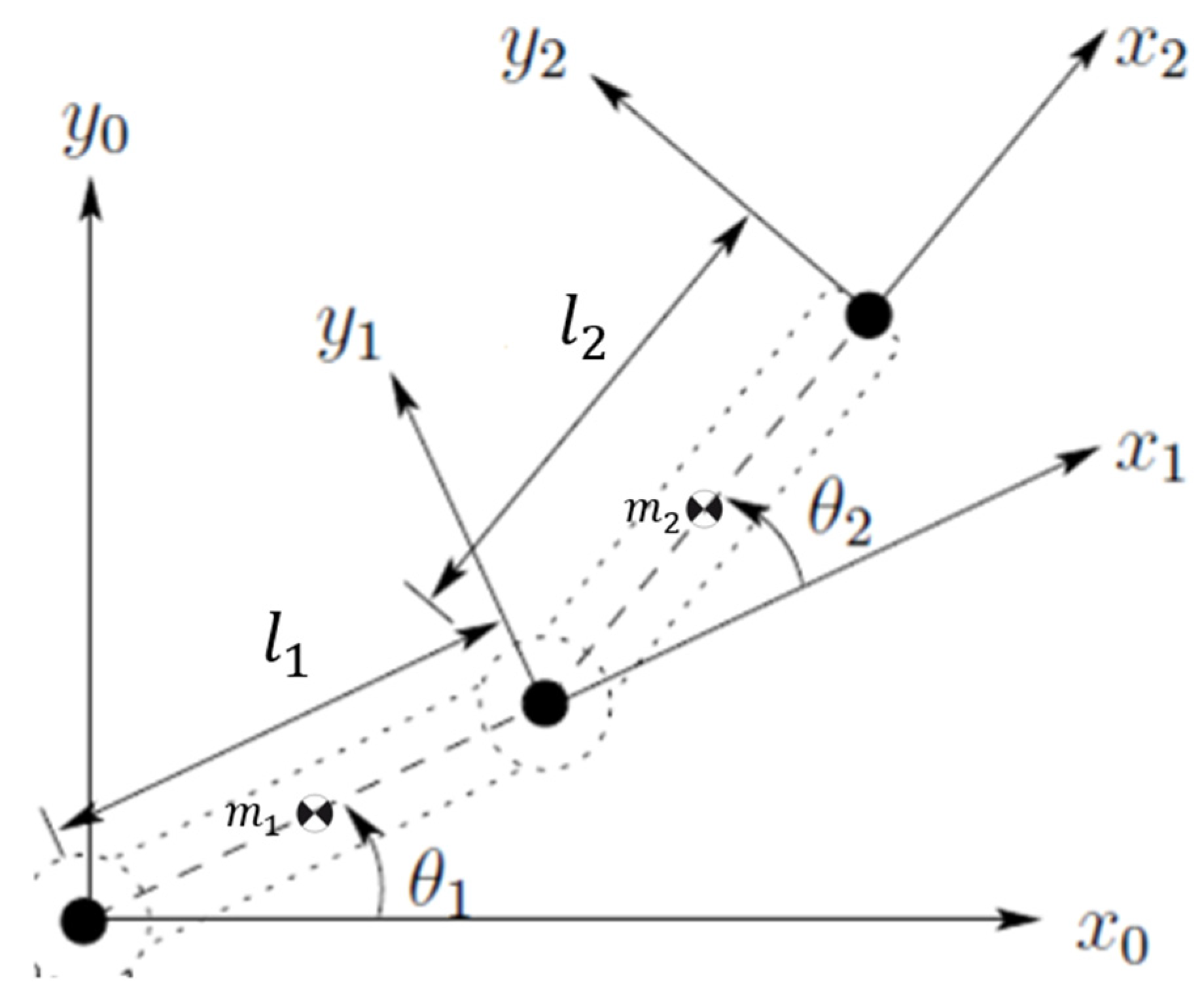
In
Figure 5, a comparison between the human upper limb and the mechanical model used for device kinematic analysis is shown. (a) An anatomical diagram of the upper limb showing key segments and joint angles involved in shoulder elevation (θ
1), arm abduction (θ
2), and elbow flexion (θ
3), along with segment lengths α
1 (upper arm) and α
2 (forearm). (b) Equivalent schematic representation of the robotic system modeled as a 2-link planar manipulator. The same angular and segment notations are used to establish biomechanical correspondence with the human limb. These values are summarized in
Table 3, which compiles the anthropometric parameters used in the kinematic modeling. Although the data correspond to five-year-old children, the chosen ranges ensure that the functional workspace also covers younger children [
20,
21].
To model the workspace, the arm was considered as an RRR manipulator with its origin at the humeral head, as shown in
Figure 5b. The position of the wrist
is obtained using the forward kinematics described by Equation (14):
From Equation (14), the Cartesian components of the wrist position are given by the following:
Since a planar end-effector device is used, the wrist remains supported on a surface at a fixed height
, imposing a vertical constraint
, which helps discard joint combinations that would push the wrist out of the movement plane,
Each joint range was discretized using uniform steps
, as shown in the following:
For each angle triplet
, Equation (14) was evaluated. If constraint (16) was satisfied, the corresponding point was added to the workspace cloud. This process was repeated over the entire joint space defined by the following bounds:
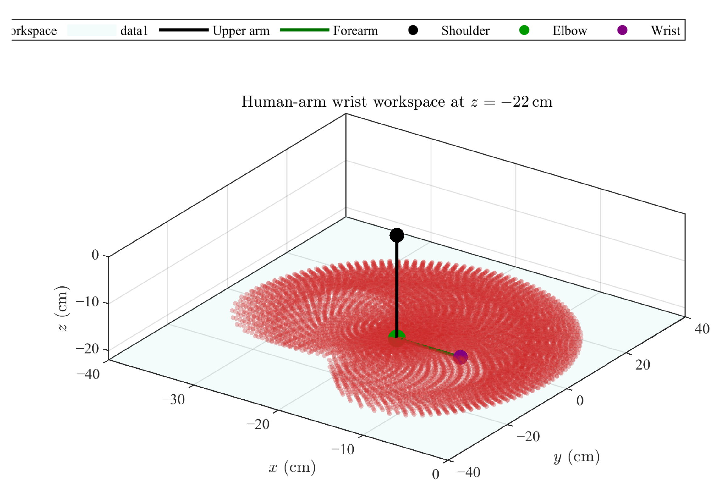
The resulting workspace, presented in
Figure 6, was obtained using MATLAB
® version 2024a. The red dots represent the reachable positions of the wrist, obtained through systematic sampling of the joint space, based on the simplified upper-limb kinematic model.
2.2.2. Geometric Synthesis and Validation of the Training Device
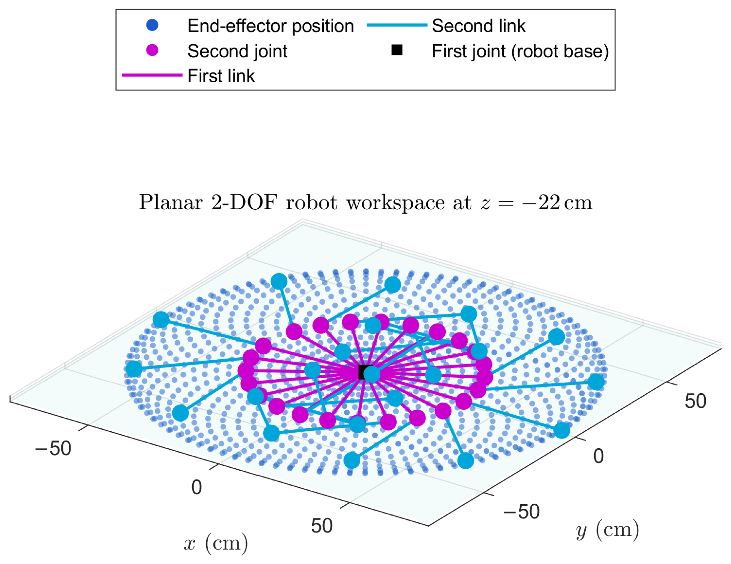
Once the functional workspace of the arm was delimited, a planar 2-DOF configuration was selected for the robot. This geometry was chosen to cover the largest possible area with the fewest number of joints (see
Figure 7). The forward kinematics of this structure are defined by Equation (21), where L
1 and L
2 denote the link lengths, and
and
represent the joint angles.
With the base fixed at the origin (0, 0), the position of the end-effector is computed as follows:
The Jacobian matrix, derived from (21), loses rank when
or
. These configurations were excluded during the workspace analysis by applying a threshold value
. A simulation was performed in MATLAB
® version 2024a with joint domains,
, with a constant step of
. The chosen link lengths were
and
, consistent with the pediatric anthropometric means previously presented in
Table 3. The resulting workspace had a ring-like shape, shown in
Figure 8, with inner and outer
y
, respectively. The blue dots indicate reachable positions of the robot’s end-effector.
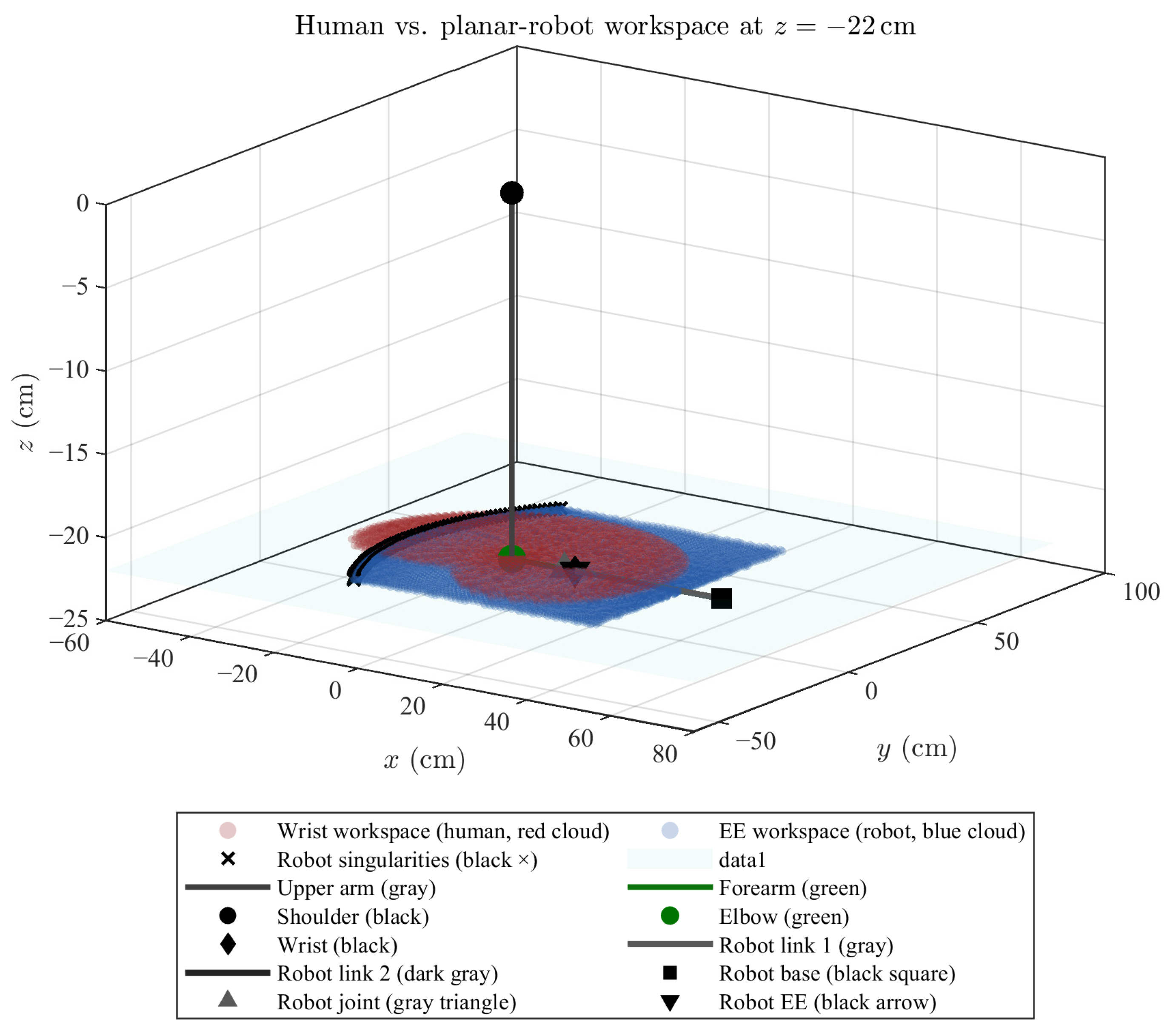
To quantify the overlap between the robot’s workspace
and the human wrist workspace
, the coverage metric
given in Equation (9) was defined. This metric expresses the percentage of human workspace points that fall within the effective reach of the robot, given a spatial tolerance
, where
are the human wrist points and
are the robot end-effector points.
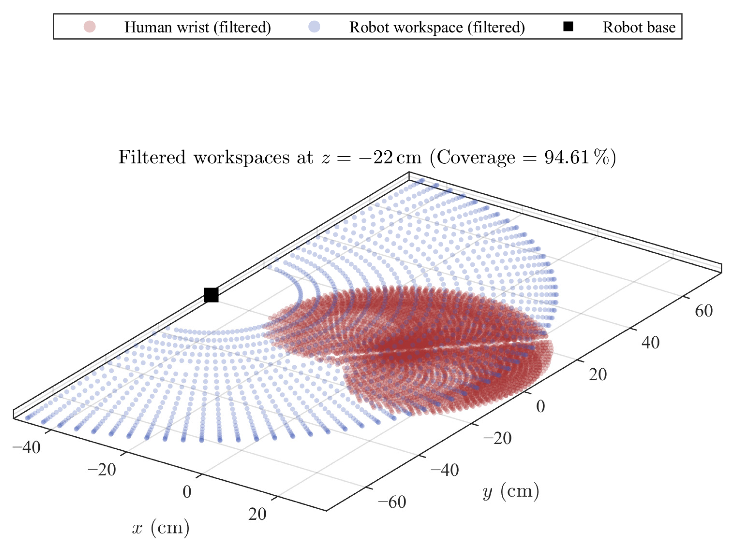
By translating the training device’s base along the x-axis, the optimal base position was found using Equation (23). This positioning yielded a coverage value , indicating high functional overlap between both workspaces.
With the selected link lengths and this base position, full workspace coverage is ensured without requiring full joint rotations, which simplifies mechanical design and facilitates sensor mounting and wiring.
Figure 9 overlays the robot workspace (in blue) with the human workspace (in red). The visual match confirms that the chosen dimensions and ranges adequately cover functional pediatric trajectories, while keeping the wrist supported on the working surface.
This geometric validation forms the foundation for the CAD model and ensures that, once the series elastic actuators are integrated, the device will preserve its assistive capabilities and maintain proper impedance decoupling.
Based on the selected base position x
0, the joint angle limits were tuned to ensure that at least 95% of the upper-limb workspace is covered. These angles are presented in Equation (24).
2.2.3. CAD Design and Fabrication Considerations for the Prototype
The mechanical design was developed using SolidWorks
® 2024, starting from the link lengths established in the previous geometric synthesis
and the minimum joint ranges
and
. To ensure anthropometric compatibility and load-bearing capacity, the weight of the pediatric upper limb was estimated based on a standard reference of 5% of total body mass, approximately [value] kg for children aged 2 to 5 years [
23,
24]. This value was used as the nominal load for structural dimensioning and actuator selection.
Figure 10 shows the 3D model of the end-effector-based device. It includes a fixed base, two rotational joints, and a cylindrical end-effector designed to accommodate different gripping accessories. Sensor integration points were included for instrumentation. Dedicated spaces were reserved for installing the SEA units, ensuring that no collisions occur throughout the full joint range.
A motion study was performed in Dassault Systèmes SolidWorks® 2024, to validate that the CAD model supports the expected volume and mass of the SEAs without interfering with the joint mechanics. The structure was also confirmed to handle the nominal load.
Before fabricating the prototype, the workspace was revalidated by considering (i) the mechanical constraints imposed by casings and motors and (ii) the optimized joint limits. The resulting workspace is shown in
Figure 11, which confirms that the required functional coverage is maintained with a safety margin. The blue cloud represents the robot’s reachable points, and the red cloud corresponds to the human anatomical workspace. The superposition exceeds 95%, and the optimal base position is marked by a black dot.
2.2.4. Dynamic Model and Rigid Actuator Selection
To properly calculate the elastic element of the SEA, it is necessary to obtain the dynamic model of the training device prototype.
Table 4 summarizes the parameters of the 2-DOF planar manipulator, derived from both the mechanical design (assuming the entire structure is manufactured via 3D printing in PLA using a 0.4 mm nozzle and 0.2 mm layer height) and the nominal load exerted by the pediatric upper limb.
In planar dynamics (i.e., ignoring gravity in the horizontal plane), the torque depends solely on the total kinetic energy, given by Equation (25):
Applying the Euler–Lagrange formulation, the dynamic model of the end-effector device is expressed as Equation (26),
where
is the inertia matrix (symmetric and positive-definite),
includes Coriolis and centrifugal effects,
is the transpose of the Jacobian matrix, and
is the torque produced by the external load (i.e., the upper limb).
The resulting matrices, derived using the parameters from
Table 2, are given by Equations (27) and (28),
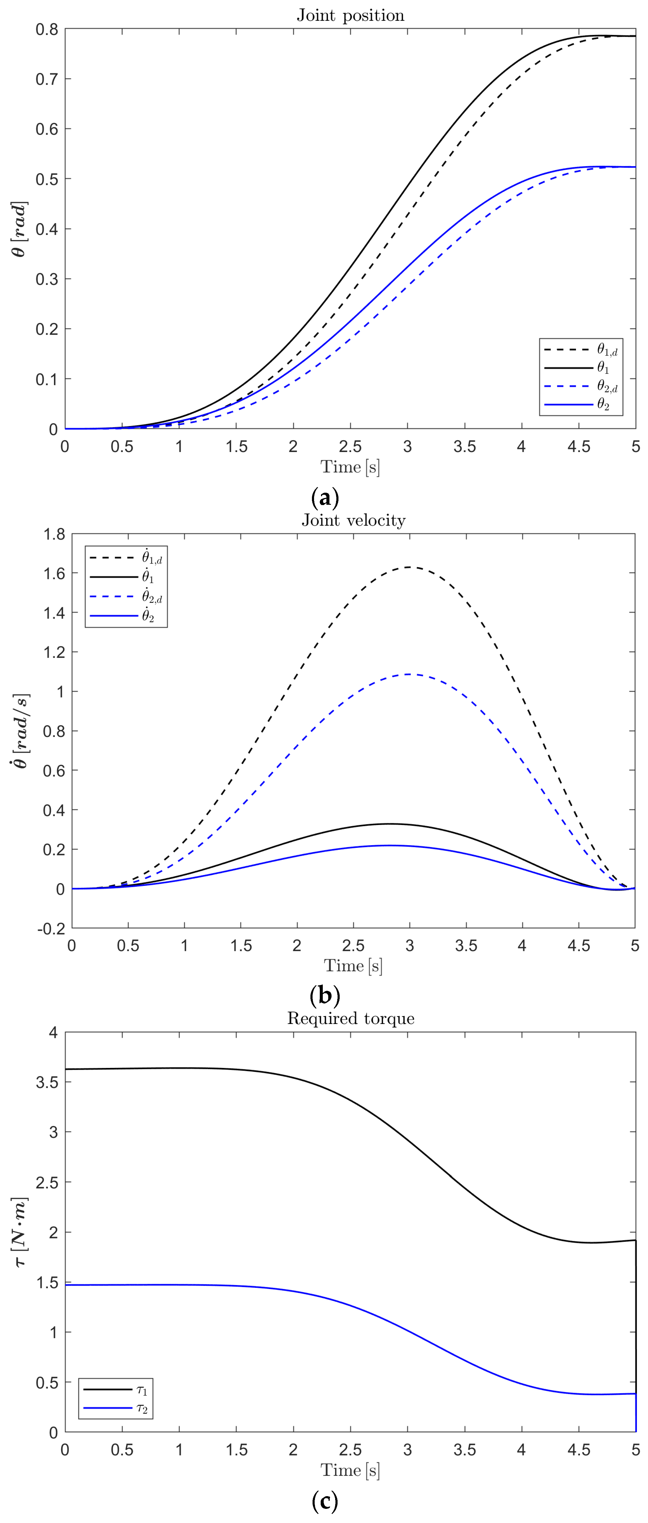
To validate the model, a simulation experiment was conducted in MATLAB®/Simulink® 2024a. Numerical integration was performed with a step size of 5 s using smooth input trajectories generated with 6th-degree Bézier polynomials, ensuring continuity in position, velocity, and acceleration along the Bernstein control points.
In
Figure 12a, the joint positions (solid lines) closely follow the reference trajectories (dashed lines), without noticeable overshoot.
Figure 12b shows the joint velocities, which remain below
, an appropriate range for pediatric rehabilitation tasks. In
Figure 12c, the required joint torques are shown; peaks of
for Joint 1 and
for Joint 2 are reached.
Both torque values fall below the continuous nominal torque limit of the Dynamixel® MX-64 motor (6.4 Nm), ensuring safety margins of at least and , respectively. These results confirm that the selected rigid actuators are suitable for implementing the SEAs in the proposed training device.
In conclusion, this simulation validated the dynamic model of the 2-DOF robotic training device using smooth reference trajectories representative of pediatric movements. The results confirm that the derived model accurately captures the system’s behavior and that the required joint torques remain within the continuous operating limits of the selected actuators.
2.2.5. Fabrication of the End-Effector-Type Training Device Prototype
The prototype of the training device was fabricated using additive manufacturing, specifically Fused Deposition Modeling (FDM). All structural components—including the links, actuator housings, and end-effector supports—were printed in PLA (polylactic acid) due to its low density, ease of fabrication, and favorable specific stiffness.
The printing was completed using a 0.4 mm nozzle, with a 0.2 mm layer height and an infill percentage of 60%. Areas expected to experience higher mechanical stress were reinforced with denser infill to enhance durability. Fastening elements (M4/M5 screws) and rotational shafts were made from commercial-grade steel to ensure sufficient rigidity in critical points.
The links were mounted on 8 mm inner-diameter ball bearings. Each joint incorporated an SEA composed of a Dynamixel® MX-64 motor, an input pulley directly coupled to the motor shaft, two antagonistically arranged springs, and an output pulley rigidly attached to the corresponding link. The custom-designed housings provided space for both springs and a threaded preload system, allowing for effective stiffness adjustment.
All electrical and signal connections were routed through integrated printed cable channels, which help protect the wiring and facilitate maintenance.
Joint positions were measured using the 12-bit encoders integrated into the MX-64 motors. For homing, mechanical limit switches were installed. The preload of each spring was measured using a linear potentiometer (0–10 kΩ) mounted on the output shaft of each joint (Output 1–2) of the SEA.
The components of
Figure 13 are highlighted as follows:
Blue: Dynamixel® MX-64 motors (Motor1 and Motor2);
Red: SEA modules (SEA1 and SEA2);
Yellow: Output pulleys connected to each joint (Output1 and Output2 with sensors);
White: Rigid links (Link1 and Link2) forming the planar manipulator structure.
One key feature of the prototype’s architecture is the integration of the SEAs directly with the joint outputs. This modular arrangement allows for independent dynamic analysis of each joint and facilitates both structural adjustments and experimental diagnostics. The setup also enables data acquisition at multiple points throughout the system, which is essential for validating the dynamic model and tracking the system’s response in real time during experimental trials.
2.3. Design of the Computed Torque Controller
To achieve accurate trajectory tracking in joint space and compensate for small disturbances—not caused by large involuntary movements—a computed-torque control scheme with proportional/derivative and integral (PD + I) action was implemented. This method linearizes the dynamics of the manipulator by canceling nonlinear terms, such that the auxiliary control signal u is applied to an equivalent unit-mass system. The design starts from the general dynamics of an n-degree-of-freedom manipulator, expressed in Equations (27) and (28). To cancel the system’s nonlinearities, a feedback law like the one in Equation (29) is proposed, where u is the auxiliary control signal.
Substituting this into the dynamics Equation (30) yields the following:
To impose a linear control law on the tracking error, we define the joint error variables as shown in Equation (31), where
is the desired trajectory.
The auxiliary control signal is then defined by Equation (32),
here
and
are diagonal gain matrices.
Substituting Equation (32) into (30), the full control law is obtained,
Under ideal tracking conditions
, the error dynamics satisfy
With the corresponding characteristic polynomial given by
To guarantee a desired settling time,
s, and critical damping
, the system is assigned three real poles, placed according to Equation (36).
In this configuration, the first two poles collapse into a double real root at
, and a third pole is positioned further to the left to ensure overdamped behavior. This results in the closed-loop characteristic polynomial, Equation (37).
In this study, a critically damped response (
) was selected, with a specified settling time
. The corresponding natural frequency was then computed using an approximation, Equation (38).
Finally, these values were substituted to obtain the controller gains:
;
;
.
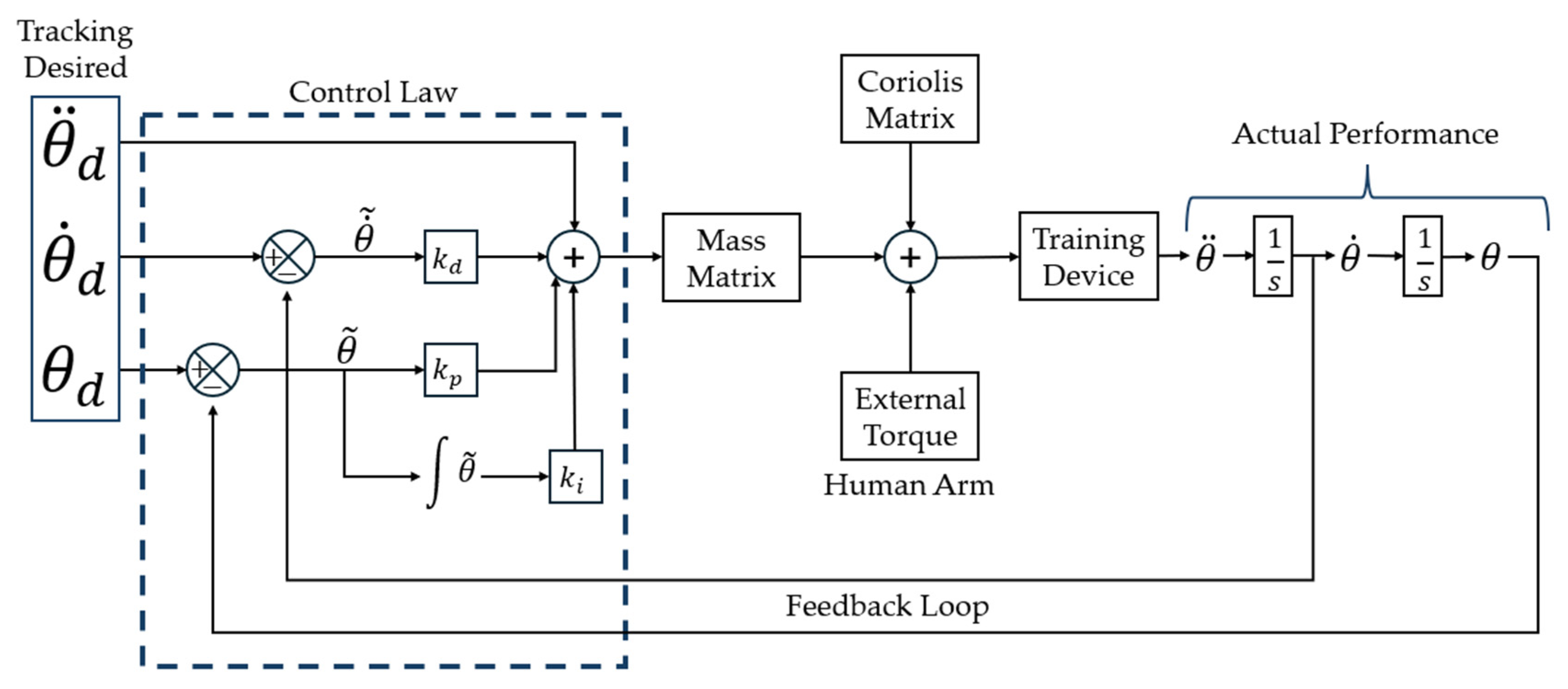
Figure 14 presents the desired trajectory
, which is generated using Bézier polynomials and serves as a reference for a linear control law that computes an auxiliary acceleration, corrected by proportional, derivative, and integral gains. This signal is dynamically compensated using the system model—mass and Coriolis matrices—to generate the total torque to be applied at each joint.
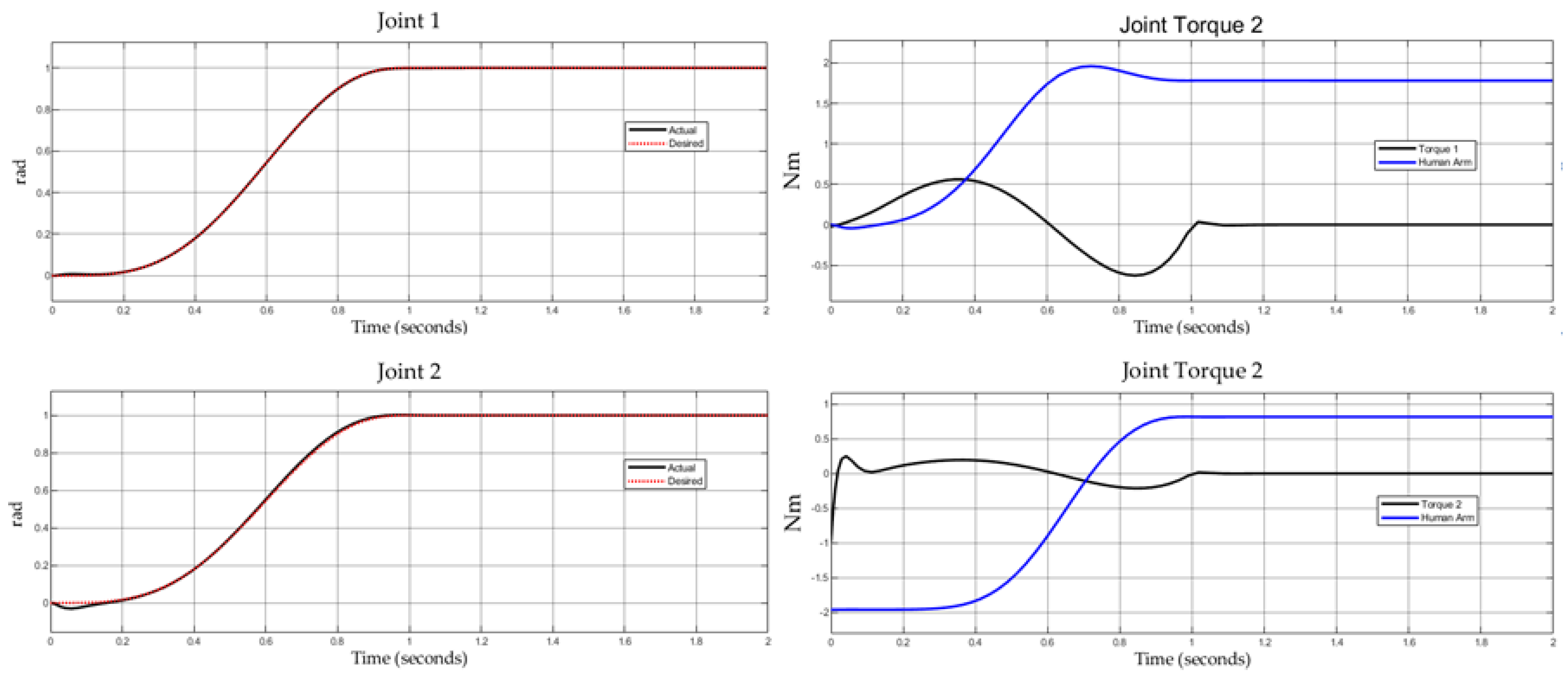
In this study, a constant external torque of −9.8 Nm was applied at the end-effector of the 2-DOF training device to simulate the interaction force typically exerted by a user’s upper limb during physical training. This disturbance was incorporated into the system dynamics as an additive torque input, as shown in
Figure 14, where the block labeled External Torque/Human Arm is connected in parallel to the plant model and the control signal.
The control strategy follows the computed-torque approach with a PD+I structure. The integral term plays a critical role in rejecting constant disturbances, ensuring zero steady-state error. The effect of the external torque is evident in
Figure 15: the control torques of both joints (right-side plots) show how the controller adapts to compensate for the applied load.
Notably, Joint 2 experiences a larger increase in control effort, as it plays a more direct role in countering the disturbance. Despite this, the position trajectories (left-side plots) remain close to the reference curves, confirming that the controller maintains tracking performance even in the presence of external interactions.
The controller was implemented on a PC with the specifications listed in
Table 5, running Windows 10. The control algorithm was executed at 1 kHz, developed in Python 3.12.1 using the Dynamixel
® SDK (Protocol 1.0).
3. Results
The experimental stage aimed to (i) verify the system’s ability to follow reference trajectories under the presence or absence of external perturbations and (ii) evaluate the compliance and backdrivability behavior enabled by the inclusion of SEAs.
In each case, spring deformation was indirectly estimated through the angular difference between the motor shaft and the actuated link, allowing it to be interpreted as a signal of physical interaction. If deformation remained within the nominal range, the system considered the user to be correctly following the reference trajectory.
Two experimental scenarios were defined with the objective of validating the passive mechanical response of the prototype, as well as the controller’s performance during physical interaction. Although the system was designed for upper-limb training in pediatric users and was dimensioned using real anthropometric data, the trajectories used during testing were not based on clinical rehabilitation movements. Instead, synthetic trajectories generated via Bézier polynomials were used, designed specifically to evaluate the system’s dynamic behavior under external perturbations and to assess its performance in terms of tracking, stability, and decoupling.
Two experimental protocols were implemented to assess the compliance and backdrivability features in the SEA-based training device, as described below.
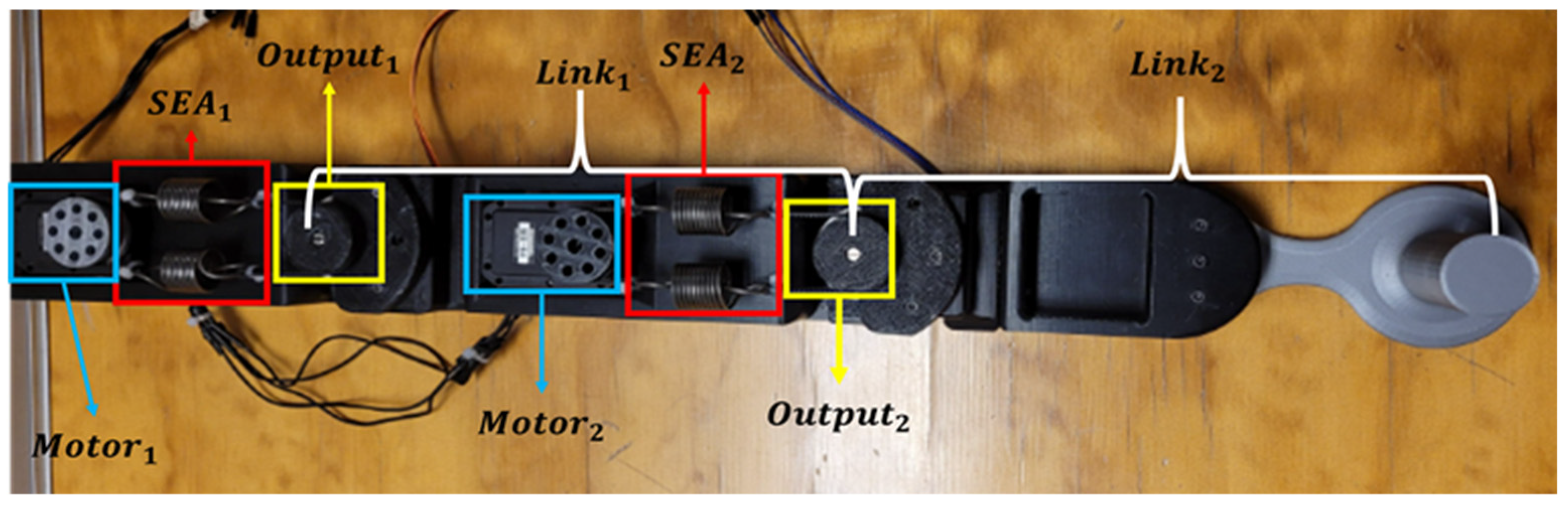
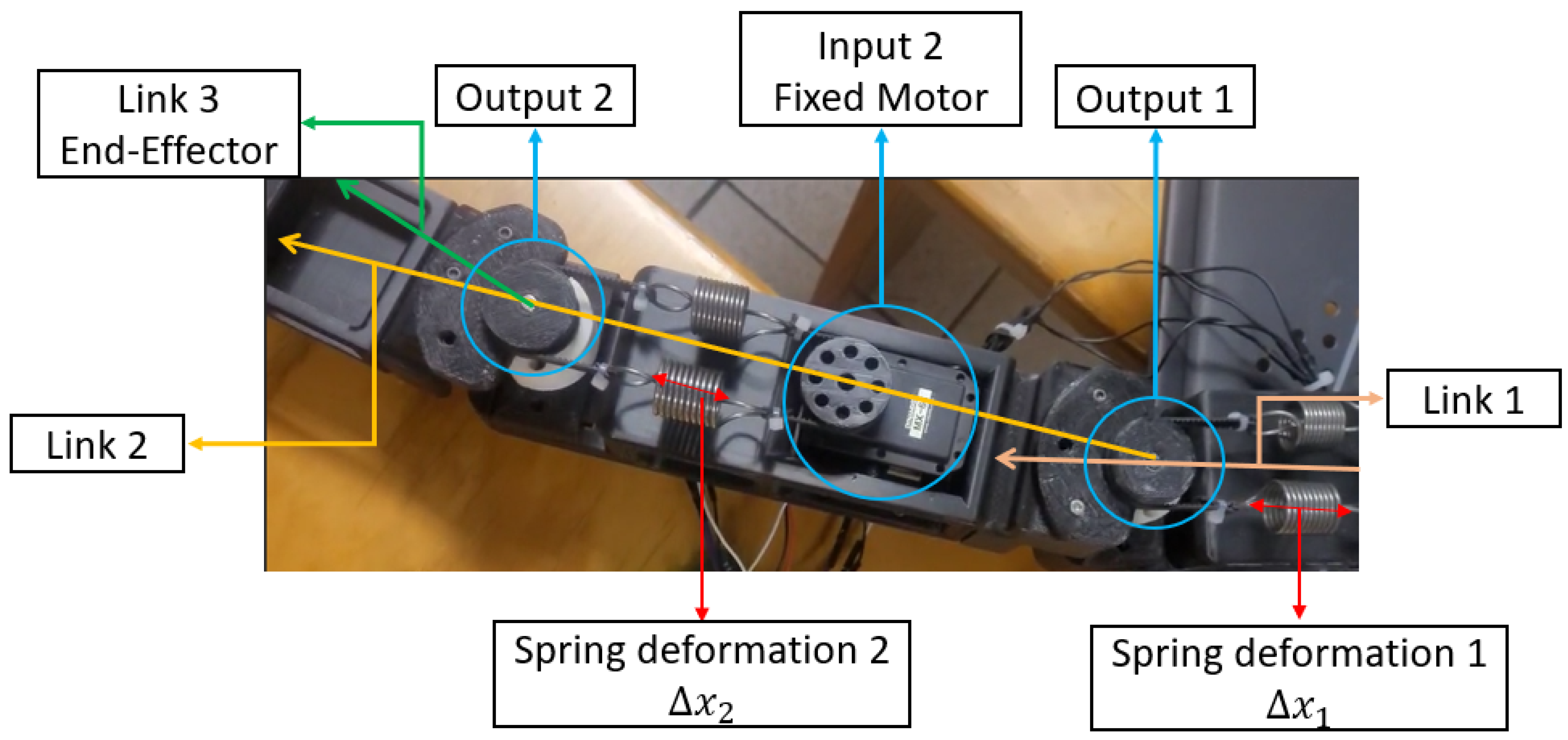
To guide the reader in interpreting the experimental results,
Figure 16 shows an annotated image of the physical prototype used in testing. The image identifies the main components of the SEA architecture, including the fixed motor inputs (Input 1 and 2), the output links, and the elastic elements that produce deformation (
and
). This visualization is key to understanding how deformation and joint displacement are represented in the experimental plots presented in
Figure 16 and
Figure 17. For instance, spring deformation occurs between the motor shaft and the actuated link, allowing for mechanical decoupling when external forces are applied.
3.1. Experiment 1: Impedance Decoupling
During this experiment, the device executed a smooth angular trajectory in both joints, generated by Bézier polynomials, with movement ranges up to ±40°. The trajectory remained constant throughout the test and was delivered as a reference to the controller. Simultaneously, an external manual perturbation was applied to the end-effector by exerting force perpendicular to the motion plane. The controller was tuned with predefined gains to gently and asymptotically correct minor trajectory tracking errors.
As a result, it was observed that the SEA spring absorbed the perturbation while the motor remained rigidly on the reference trajectory without losing stability or precision.
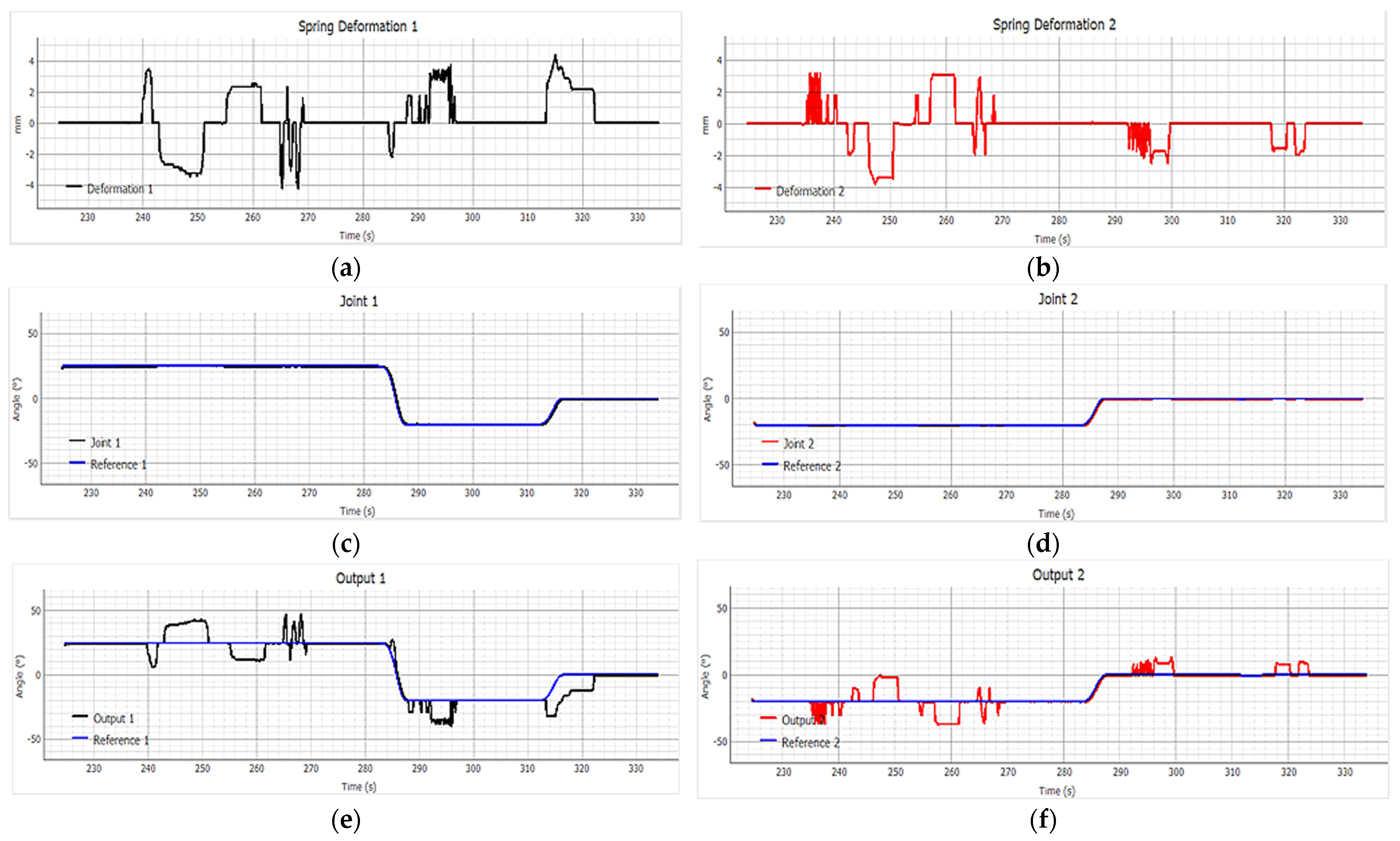
Figure 17 shows how, during the application of external perturbations, the motors of the device actively follow the reference trajectory.
Graphs in
Figure 17a,b present the spring deformation at Joint 1 and Joint 2, respectively, showing how the compliant elements absorb the external torque, reflected in the deformation (in millimeters) of the SEA elastic elements at each joint. These curves indicate how much the spring compresses or stretches under external forces. In
Figure 17a, between 240 and 250 s, a sequence of positive and negative peaks reaching up to ±4 mm is observed, demonstrating that the spring is actively absorbing the energy of the applied perturbation. Similarly,
Figure 17b shows peaks within the same time range, suggesting that both joints were affected by the same external interaction.
In
Figure 17c,d, the angular position of the motors at Joint 1 (black line) and Joint 2 (red line) is shown, which closely follows the reference trajectory even in the presence of perturbation. In the time interval from 230 s to 330 s, the motor position (Joint 1 and Joint 2) tracks the reference (blue line) with minimal error, validating that the motors are not directly affected by the applied external force.
Figure 17e,f show the angular position of the output links (Output 1 and Output 2), where deviations from the reference indicate that the perturbation is transmitted to the load but not to the actuator, thus validating the system’s mechanical impedance decoupling. In the 240 s–250 s interval,
Figure 17e shows how Output 1 (black line) diverges from the reference trajectory (blue line). This behavior aligns with the deformation peaks observed in
Figure 17a (Spring Deformation 1), indicating that the deviation results from spring deformation. Similarly,
Figure 17f (Output 2) shows significant oscillations between 240 s and 260 s, in parallel with the deformations seen in
Figure 17b (Spring Deformation 2).
By comparing the signals in the 240 s–250 s range,
Figure 17c (Joint 1) with
Figure 17e (Output 1), a tracking error increase is observed between Output 1 (red line) and the reference (blue line). This error indicates that the perturbation affected Joint 1, causing spring deformation (
Figure 17a), which enables decoupling between the motor and output while the motor continues following the programmed trajectory without alteration (
Figure 17c).
In general, spring deformations (
Figure 17a,b) occur exactly when the output (
Figure 17e,f) deviates from the reference, while the motor position (
Figure 17c,d) remains constant. This temporal synchronicity confirms the dynamic decoupling provided by the SEAs: external forces do not directly affect the motors but are absorbed by the spring, allowing the motor to precisely control the desired trajectory.
Subsequently, in the interval from 270 s to 290 s, the Output 1 and 2 signals (
Figure 17e,f) gradually correct the tracking error, while the spring deformation (
Figure 17a,b) stabilizes around zero, indicating that the perturbation energy has been fully dissipated. The natural restoration of the trajectory without overshooting or instability validates the SEA’s role as a mechanical damper, providing passive safety and global system stability.
The behavior observed in
Figure 17 confirms that the SEA-based design provides the desired properties of compliance, backdrivability, and impedance decoupling. This adaptive response capability—without sacrificing tracking precision—is essential in pediatric physical training contexts, where unpredictable user interaction may compromise safety if not properly managed.
3.2. Experiment 2: Perturbation Absorption with Fixed Motor
During this test, the motors were intentionally turned off, and an external torque was manually applied to the end-effector to evaluate the backdrivability and energy absorption of the SEA-based joints. In this second experiment, the device operated in passive mode by disabling motor torque, ensuring no controller intervention.
During the trial, the spring deformation and the angular displacement of the joints were recorded. This configuration allowed experimental validation of the backdrivability property (the ability of the system to allow movement at the output without rigid motor resistance). The system responded to the perturbation by allowing movement of the end-effector without generating rigid opposition from the actuator, demonstrating that the design is safe, absorptive, and suitable for uncontrolled physical interaction.
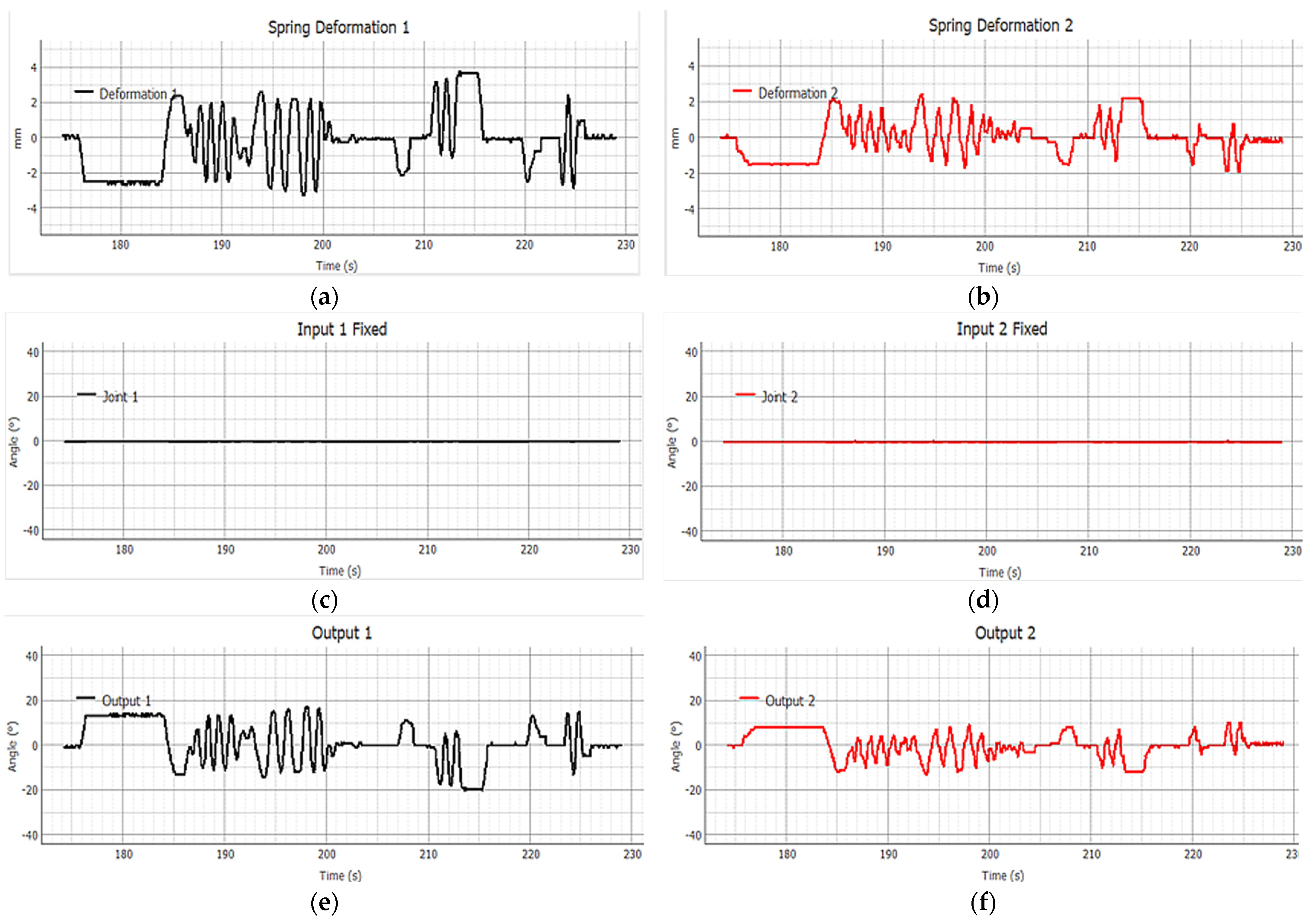
Figure 18 illustrates the system’s behavior in the absence of active control.
Figure 18a,b: spring deformation at Joint 1 and Joint 2, showing the elastic elements’ response to the applied perturbation.
Figure 18c,d: motor joint angle, Input 1 and Input 2, which remain constant during the test, confirming the lack of active control.
Figure 18e,f: output joint angle, demonstrating that the system responds to external perturbations through passive motion, validating actuator–load decoupling.
In
Figure 18c (Input 1 Fixed) and
Figure 18d (Input 2 Fixed), the signals remain at zero throughout the time interval, indicating that the motors are completely locked, with no angular variation.
However, in
Figure 18e (Output 1) and
Figure 18f (Output 2), significant oscillations are observed despite motor immobility. Specifically, between 185 s and 215 s, the output signals vary continuously in response to the external perturbations applied to the end-effector. This system response, in the absence of motor action, confirms that the device can be driven from the output to the input—a fundamental property known as backdrivability.
Figure 18a,b show the spring deformation (in mm) of each SEA. In particular, alternating compression and extension peaks are observed between 180 s and 220 s, indicating that the springs are absorbing and releasing energy as the system reacts to external perturbations. The repetitive and continuous nature of these signals demonstrates the spring’s passive response to external stimuli.
Correlating the three graph sets in
Figure 18 reveals the backdrivability phenomenon: the motors remain fixed (
Figure 18c,d) during the entire interval, yet the output links (
Figure 18e,f) move in accordance with the perturbations (e.g., 185–200 s), and this response is governed by spring deformation (
Figure 18a,b).
This laboratory behavior is consistent with the simulation results shown in
Figure 4, a simulation of an SEA under external sinusoidal perturbation applied to the output, with a fixed motor position. In both cases, the system demonstrates an efficient passive response that decouples physical interaction from the rigid actuator, without requiring active control.
These results confirm that the SEA-based architecture grants the system key capabilities in safety and adaptability. The device’s ability to respond to external forces without controller intervention—through passive elements—is crucial in scenarios where users may generate involuntary or unpredictable motions, such as in pediatric training contexts. The clarity and consistency of these observations reinforce the validity of the proposed design and support its application in real-world physical human–robot interaction environments.
4. Conclusions
The results of this study demonstrate that the proposed dual-spring SEA represents a robust and safe solution for physical training devices requiring adaptable physical interaction. Its integration into a planar, end-effector-type architecture specifically dimensioned for pediatric users allows for effective impedance decoupling between the motor and the load, granting the system compliance and backdrivability—key features in applications where passive safety is essential.
Laboratory validation evidenced that the system is capable of absorbing external perturbations via spring deformation, without overloading the motors or compromising trajectory tracking at the end-effector. In particular, smooth passive restoration of the desired trajectory after the perturbation ceased confirmed the system’s ability to adapt to unexpected interactions without active control.
Additionally, passive-mode experiments with locked motors confirmed the output’s ability to drive the system, experimentally validating the backdrivable behavior of the actuator. This feature is especially relevant in pediatric applications, where user motion is inherently variable and the system’s ability to yield to external forces reduces mechanical and ergonomic risks.
Compared to recent works, this study contributes key experimental evidence that complements and extends prior developments. While studies like [
1,
13] focus on ideal conditions or active control, this work validates SEA behavior under real physical disturbances, including passive-mode performance in an upper-limb training device. Laboratory experiments revealed passive energy absorption through spring deformation without motor intervention, empirically confirming mechanical impedance decoupling and the ability to allow angular output motion despite actuator immobility, validating backdrivability. Moreover, the smooth return of the system output to the reference trajectory after perturbation confirms its adaptability and stability.
Unlike [
25], the approach validated here focuses on a planar system adapted for pediatric upper limbs, expanding its functional range in clinical and assistive contexts and offering a safe and viable alternative for training devices at early ages. Similarly, although [
26] presents a variable stiffness actuator with torque control via adaptive tuning, its experimental analysis is limited to ideal conditions without physical interaction or passive-mode validation. This study explicitly analyzes the SEA response under perturbations and with the motor deactivated, confirming its role as a mechanical filter and enabling safe interaction without active control.
Altogether, this study establishes a solid foundation for the use of SEAs in the design of physical training devices focused on mechanical safety, implementation simplicity, and user variability adaptability. The inclusion of elastic elements in simple architectures—such as the one proposed—emerges as an effective strategy for fostering safe and functional interaction environments, especially in early stages of motor development.
Given that the designed prototype, in accordance with the international conformity assessment principles for medical devices outlined by the Global Harmonization Task Force [
27], is intended to support motor function through rehabilitation processes, it is classified as a Class II medical device with moderate risk. Consequently, its development must follow the stage-gate innovation framework and technology readiness levels (TRLs) defined for medical device design [
28,
29].
According to these frameworks, early-stage validation begins at the laboratory level with proof-of-concept demonstrations (TRL 3), followed by functional performance testing of the prototype in controlled lab settings (TRL 4). Only after successfully completing these phases can preclinical trials with healthy users (TRL 5) be conducted. Based on the outcomes of these preclinical evaluations, protocols for clinical validation and eventual product commercialization can be established (TRL 6 and TRL 7).
This article presents the results corresponding to TRL 3 and TRL 4 stages, in which the system was experimentally validated under laboratory conditions. Future work, in collaboration with healthcare professionals, will aim to define the appropriate medical protocol required for preclinical and clinical testing of the developed robotic training device.


