Article

Fuzzy Adaptive Control for a 4-DOF Hand Rehabilitation Robot

1
CESTER-Research Center for Industrial Robots Simulation and Testing, Technical University of Cluj-Napoca, 28 Memorandumului Street, 400114 Cluj-Napoca, Romania
2
European University of Technology, European Union
3
Neurology I Department, Cluj-Napoca Emergency Clinical County Hospital, 400012 Cluj-Napoca, Romania
4
Neurology Department, University of Medicine and Pharmacy “Iuliu Hatieganu”, 400012 Cluj-Napoca, Romania
5
Department of Neurology, Clinical Municipal Hospital, 400139 Cluj-Napoca, Romania
6
Department of Neurophysiology, National Center for Spinal Disorders, 1126 Budapest, Hungary
7
MEtRICs Research Centre, School of Engineering, University of Minho, Campus of Azurém, 4800-058 Guimarães, Portugal
8
Technical Sciences Academy of Romania, B-dul Dacia, 26, 030167 Bucharest, Romania
*
Author to whom correspondence should be addressed.
Actuators 2025, 14(7), 351; https://doi.org/10.3390/act14070351
Submission received: 6 May 2025 / Revised: 14 July 2025 / Accepted: 16 July 2025 / Published: 17 July 2025

Abstract

This paper presents the development of a fuzzy-PID control able to adapt to several robot–patient interaction modes by monitoring patient evolution during the rehabilitation procedure. This control system is designed to provide targeted rehabilitation therapy through three interaction modes: passive; active–assistive; and resistive. By integrating a fuzzy inference system into the classical PID architecture, the FPID controller dynamically adjusts control gains in response to tracking error and patient effort. The simulation results indicate that, in passive mode, the FPID controller achieves a 32% lower RMSE, reduced overshoot, and a faster settling time compared to the conventional PID. In the active–assistive mode, the FPID demonstrates enhanced responsiveness and reduced error lag when tracking a sinusoidal reference, while in resistive mode, it more effectively compensates for imposed load disturbances. A rehabilitation scenario simulating repeated motion cycles on a healthy subject further confirms that the FPID controller consistently produces a lower overall RMSE and variability.

1. Introduction

Finger impairment represents a significant burden worldwide. Studies have revealed that millions of patients worldwide require finger rehabilitation following neurological conditions like stroke, multiple sclerosis, or peripheral neuropathies, but also local osteoarthritis, degenerative joint diseases, traumatic injuries, or surgical interventions [1,2]. The prevalence of neurological conditions such as post-stroke hemiparesis and complex regional pain syndrome leads to a high demand for finger rehabilitation therapies that rebuild neuronal paths, restore functional independence and, improve patients’ quality of life [3,4]. Conventional approaches for hand and finger rehabilitation usually involve manual therapy, passive and active-assisted exercises, repetitive motions, and functional daily task training [5,6]. Classical rehabilitation techniques show considerable efficiency in accessing neuroplasticity, restoring range of motion, and improving motor coordination. These outcomes are limited by the variability of human-delivered therapy, fatigue, and low quantitative feedback, thus often resulting in inconsistent treatment intensity and variability between therapists [7,8]. Moreover, there is a shortage of physiotherapists, and the time available for each patient is insufficient. Robotic rehabilitation systems emerged in the last decade as a solution to the above limitations. Robotic exoskeletons and cable-driven devices provide a valuable alternative to classical rehabilitation by delivering repeatable, controlled, reproducible patterns for finger rehabilitation [9,10]. A rehabilitation robot can deliver high-intensity, high-repetition training while ensuring progress assessment of patients during the rehabilitation through integrated sensor systems, thus improving motor recovery [11].
Robotic rehabilitation devices also present some limitations. Classical robotic systems that rely on fixed-gain controllers struggle to adapt to patient-specific dynamics and nonlinearities introduced by actuation systems [12,13,14,15,16], and complex interactions between the patient and the robot demand a high level of safety and adaptability [17,18,19,20]. To overcome these limitations, advanced control strategies, such as PID variants, FPID controllers, and Model Predictive Control (MPC) systems, have been developed over time [21,22,23].
Classical PID controllers have been widely used due to their simplicity and robustness in a variety of applications [24]. Early developments on PID tuning [25] have laid the groundwork for PID application in rehabilitation robotics, revealing that fixed parameters can lead to performance degradation under nonlinear conditions. FPID controllers, developed by integrating fuzzy logic into the conventional PID framework, adapt control gains in real time in order to effectively accommodate the system to uncertainties and dynamic variations during therapy [26,27]. Recent work describes the implementation of MPC schemas for their ability to anticipate future errors and adjust control actions accordingly, enhancing response time and reducing overshoots in complex rehabilitation approaches [28,29,30]. Recent publications have reported significant performance improvements using these adaptive control strategies, especially when integrated with comprehensive kinematic models and cable tension management protocols [31,32,33,34,35]. Furthermore, recent advances in robot-assisted therapies, like wearable robotic gloves, have demonstrated promising therapeutic effects in enhancing hand function among chronic stroke patients, offering clinicians an innovative tool for upper extremity rehabilitation [36].
Recent studies in intelligent systems and soft robotics further highlight the trend toward incorporating adaptive, context-aware modeling into actuator and sensor design. For instance, Peng et al. [37] proposed a cognitive computing framework to predict the flow status of a flexible rectifier in unsteady conditions, demonstrating the power of intelligent inference in nonlinear, dynamic systems. Similarly, Mao et al. [38] developed a multimodal strain sensing system for accurate shape recognition in tensegrity structures, which are inherently compliant and require robust feedback models. These contributions emphasize the importance of integrating data-driven or fuzzy reasoning approaches with physical modeling to improve prediction, control, and adaptation. Our study aligns with this direction by embedding a fuzzy-PID control scheme into a cable-driven finger exoskeleton to enable responsive, human-like motion under real-world uncertainties, such as friction, backlash, and variable joint stiffness.
The aim of this paper is to develop an adaptive control system for a 4-DOF finger rehabilitation robot. This robot employs paired servomotors with cable actuation to manage both the flexion/extension movements of the fingers and the thumb. This actuation strategy assures that paired motors operate in opposite directions to maintain constant cable tension. Furthermore, the robot incorporates a safety mechanism that monitors joint torques. When a predefined torque threshold is exceeded, the system halts movement and awaits therapist validation, offering options to continue, stop, or reverse the motion. In this context, we compare a classical PID controller with a fuzzy-PID controller.
This paper is organized as follows: The Introduction reviews the clinical need for enhanced hand rehabilitation solutions and discusses the limitations of conventional control strategies when applied to hand rehabilitation robots. In the Materials and Methods section, we detail the design of a 4-DOF hand rehabilitation robot, providing a thorough derivation of its kinematic model, and describe the implementation of fuzzy-PID (FPID) controllers. The Results section presents comprehensive simulation data comparing the performance of the FPID controller with respect to a conventional PID controller across three interaction modes—passive, active–assistive, and resistive—including quantitative metrics such as RMSE, overshoot, settling time, and error standard deviation. The Discussion section analyses and interprets these findings, examining the advantages of the FPID controller and its implications for patient safety and rehabilitation efficacy. Finally, the Conclusion summarizes the key contributions of the study, outlines the limitations of the proposed approach, and proposes directions for future research.

2. Materials and Methods

This section describes the methods used in the development of the control system for the hand rehabilitation robot. The starting phase is represented by the definition of the medical protocol for robotic-assisted hand rehabilitation.

2.1. Medical Protocol for Robotic-Assisted Hand Rehabilitation

The rehabilitation process starts with the initial evaluation of the patient, after receiving approval from the neurological doctor. The initial clinical assessment of the patient includes an evaluation of the range of motion (ROM) for each joint of the finger using a goniometer. The values for the metacarpophalangeal (MCP), proximal interphalangeal (PIP), distal interphalangeal (DIP) joints (for fingers), and the thumb’s carpometacarpal (CMC), metacarpophalangeal (thumb MP), and interphalangeal (thumb IP) joints are recorded. Figure 1 presents the lengths of the fingers and the targeted rehabilitation joints [39].
Based on the interaction modes between the patient and the robot defined with respect to the state of the patient, three different interaction modes are defined, with each interaction mode requiring a personalized protocol:
Passive Robotic-Assisted Interaction Mode Protocol (PRAIMP) refers to the acute state of the patient (immediately after trauma) and has the objective of preventing joint contracture, minimizing spasticity, and providing controlled passive motion. Active–Assistive Robotic Interaction Mode Protocol (AARIMP) refers to the patient in sub-acute phase and is designed to reactivate motor pathways by combining patient-initiated motion with robotic assistance. Resistive and Strengthening Robotic Interaction Mode Protocol (RSRIMP) refers to the patients in chronic phase and is intended to enhance muscle strength and control by introducing graded resistance during movement. The robot is capable of adapting to the patient’s performance, whether they are able to do more or less of the therapy. The above protocols are each presented in Table 1.

2.2. Description of the Hand Rehabilitation Robot

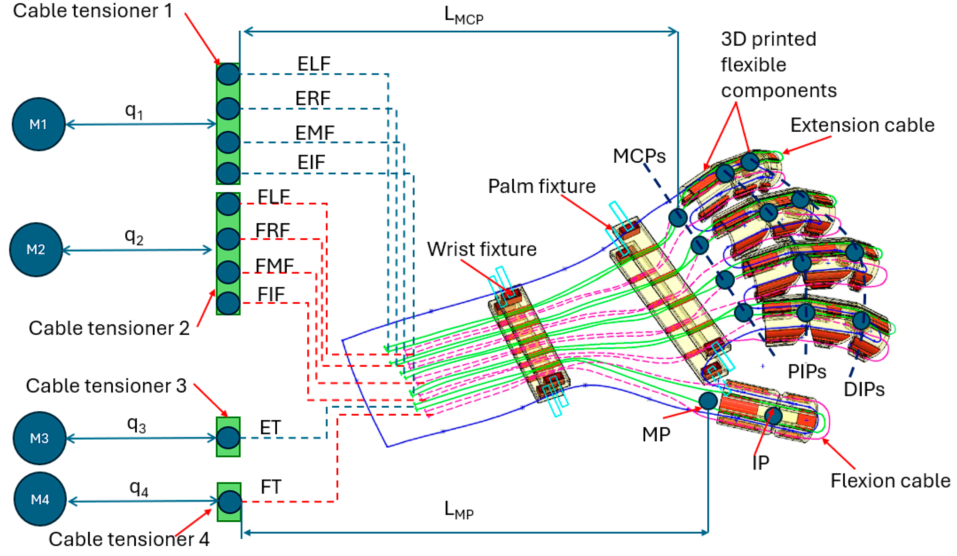
The robotic solution for hand rehabilitation proposed within this paper is presented in Figure 2 [40].
The finger rehabilitation robot is designed as a flexible robot able to perform flexion and extension of the fingers, having the innovative aspect of being customizable for each finger based on the anthropometric characteristics of the patients’ fingers. The envelope for one finger is 3D-printed into a single component, eliminating the need to use different assembly components. The robot is composed of 5 3D-printed finger envelopes (little finger, ring finger, middle finger, index finger, and thumb) designed as whole bodies, eliminating the classical revolute joints that usually present rehabilitation robots. The robot allows for a finger envelop configuration in order to perform two sets of motion: flexion and extension of the thumb and the flexion–extension of the rest of the fingers. For the little, ring, middle, and index fingers, the motor M1 is used to perform the extension motion while the motor M2 is used to perform the flexion motion. During the M1 motion, the M2 motor moves in the opposite direction, and the same is applied during the M2 motion in order to maintain the cable tension. The same principle is applied for the thumb. The cables from extension of the little finger (ELF), extension of the ring finger (ERF), extension of the middle finger (EMF), and extension of the index finger (EIF) are connected to the cable tensioner 1, which slides along q1. The cable tensioner 1 is attached to the motor M1 through a cable that threads around the pulley of M1. The cables from flexion of the little finger (FLF), flexion of the ring finger (FRF), flexion of the middle finger (FMF), and flexion of the index finger (FIF) are connected to the cable tensioner 2, which slides along q2. The cable tensioner 2 is attached to the motor M2 through a cable that threads around the pulley of M2. The cable from the extension of the thumb (ET) is connected to the cable tensioner 3, which slides along q3. The cable tensioner 3 is attached to the motor M3 through a cable that threads around the pulley of M3. The cable from the flexion of the thumb (FT) is connected to the cable tensioner 4, which slides along q4. The cable tensioner 4 is attached to the motor M4 through a cable that threads around the pulley of M4.
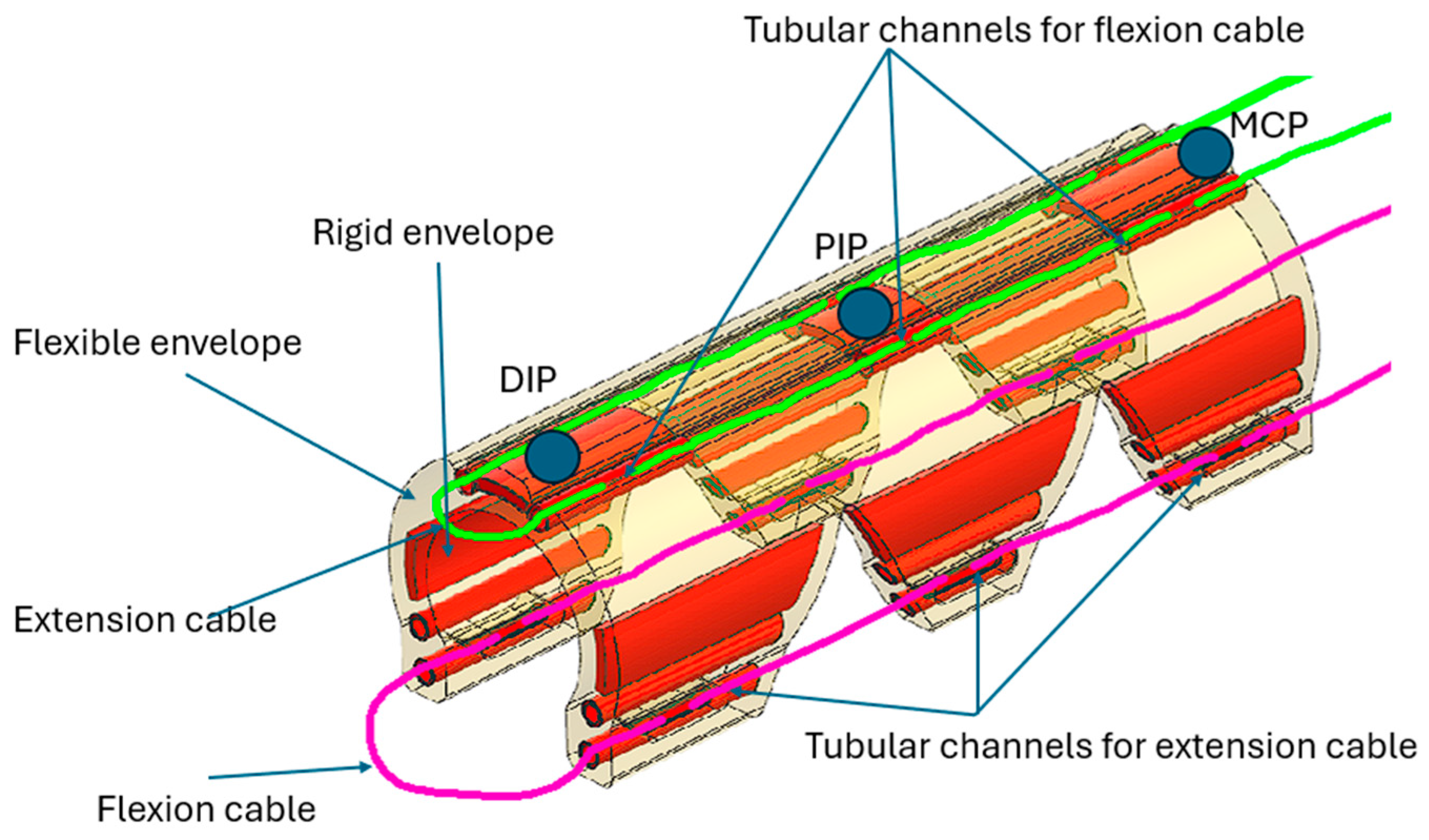
The envelope for one finger is presented in Figure 3. The finger envelope is composed of a single 3D part containing both flexible and rigid parts. The cable for the extension motion is threaded through a series of tubular channels designed in the superior rigid envelope, while the flexion cable is inserted through a series of tubular channels designed in the inferior part of the envelope.
Following the concept design description, the kinematic model of the robot is defined. To simplify the problem, the kinematic model for the index finger and the one for the thumb are presented. The notations from Table 2 are used to compute the kinematic model.
The input data for the forward kinematic model are represented by the values of the active joints, the M1, M2, M3, and M4 motors, respectively. Motor M1 rotates a pulley with diameter D. Let q1 and q2 represent the angular positions of the flexion and extension motor, respectively. Although both motors operate pulleys of equal diameter D, the effective cable displacement per motor angle differs due to path-dependent tensioning and friction, represented by efficiency coefficients for cable routing (flexor/extensor) accounting for slack, friction, or path difference (η1 and η2):
Δ L f l = η 1 D 2 q 1 Δ L e x t = η 2 D 2 q 2
Let the nominal cable length from the cable tensioner to the MCP joint be denoted by LMCP,0, when the motor rotates and pulls ΔL of cable, the new length becomes:
L M C P = L M C P , 0 ( Δ L f l Δ L e x t )
Due to the geometry of the cable attachment and routing over a virtual arc, this change results in flexion of the MCP joint. Assuming the neutral (fully extended) configuration corresponds to θ1 = 0, the joint angle increases with cable shortening:
θ 1 = f ( L M C P )
For small angles or linear approximations, the relationship simplifies to:
θ 1 k 1 ( L M C P , 0 L M C P ) = k 1 ( Δ L f l Δ L e x t ) or ,   θ 1 k 1 Δ L
where k1 is a geometry-dependent constant determined by the tendon routing configuration.
The motion of the PIP and DIP joints is coupled mechanically to that of the MCP joint, meaning that the cable arrangement and the mechanical design impose a (nearly) fixed distribution of rotation among the joints. One typical assumption is that the overall bending is distributed proportionally over the three joints. Thus, one may set:
θ 2 = k 2 θ 1 θ 3 = k 3 θ 1
where k2 and k3 are constants that depend on the finger’s biomechanics and the design of the rehabilitation robot and satisfy the relation 1 + k2 + k3 = K, where K is a fixed factor that matches the maximum achievable flexion of the entire finger.
Once the joint angles are obtained, the fingertip coordinates can be computed:
x t i p = L 11 cos θ 1 + L 12 cos ( θ 1 + θ 2 ) + L 13 cos ( θ 1 + θ 2 + θ 3 ) , y t i p = L 11 sin θ 1 + L 12 sin ( θ 1 + θ 2 ) + L 13 sin ( θ 1 + θ 2 + θ 3 ) .
Using Equations (2) and (3), the inverse kinematics for the finger rehabilitation can be determined:
θ 1 = k 1 D 2 ( η 1 q 1 η 2 q 2 )
Yielding:
q 1 = 2 θ 1 k 1 D η 1 ( η 1 q 1 η 2 q 2 ) q 2 = η 1 η 2 q 1 2 θ 1 k 1 D η 2
The joint velocity is obtained in Equation (9) and the acceleration of the joint is computed in Equation (10).
θ ˙ 1 = k 1 D 2 ( η 1 q ˙ 1 η 2 q ˙ 2 )
where θ ˙ 1 represents the angular velocity of the joint and q ˙ 1 , q ˙ 2 are the angular velocities of the motors.
θ ¨ 1 = k 1 D 2 ( η 1 q ¨ 1 η 2 q ¨ 2 )
To determine the kinematics of the thumb, the same steps are applied with respect to the geometric parameters of the thumb rehabilitation module.
Human finger joints exhibit complex, nonlinear mechanical properties that vary significantly across individuals and rehabilitation phases. Factors such as passive tissue stiffness, joint viscosity, spasticity, and muscular effort introduce patient-specific dynamics that must be accurately modeled to achieve clinically meaningful control. Unlike simplified kinematic approaches, our model incorporates nonlinear joint biomechanics that respond to both the position and velocity of the finger segments.
The joint torque is represented as:
τ joint = I θ ¨ + B ( θ ) θ ˙ + K ( θ ) ( θ θ 0 ) + τ m u s c l e
where I is the moment of inertia of the finger segment; θ ¨ is the angular acceleration of the joint; B ( θ ) is the damping function representing viscous resistance, denoting the increase in resistance during large-amplitude or faster motions, computed in Equation (12); and K ( θ ) is the stiffness function, accounting for passive elastic tissues. This nonlinearity reflects the saturation behaviour during flexion–extension and the exponential resistance near joint limits.
As defined in Equation (13), θ 0 represents the neutral joint position (full extension); and τ m u s c l e = A ρ ( t ) is the time-varying external torque representing tone, reflex activity, or voluntary contraction, where A is an amplitude scaling factor and ρ ( t ) is a control disturbance function (step, burst, noise).
B ( θ ) = B 0 + B 1 θ
K ( θ ) = K 0 + K 1 tanh ( α θ )
By adjusting K0, K1, B0, B1, A, and α, this model can emulate various clinical profiles—from flaccid paralysis (low tone, low stiffness) to hypertonic spasticity (high stiffness, high damping, strong involuntary torque). These dynamics provide a foundation for simulating personalized rehabilitation scenarios, evaluating controller robustness, and eventually adapting parameters in real time based on motor torque feedback.
In tendon-driven robotic systems, such as the one proposed in this study, the transmission of torque from the actuator to the joint is mediated by flexible cables routed over pulleys and through sheaths. While cable-driven actuation offers advantages in terms of compactness, safety, and compliance, it introduces significant nonlinear mechanical behaviour that must be explicitly modelled to achieve precise, stable, and adaptive control.
Failure to account for these nonlinearities—especially in clinical rehabilitation—can lead to degraded performance, overshoot, unintended joint motion, and poor patient safety. The most prominent non-idealities in cable transmissions are elasticity, backlash, hysteresis, and friction. Each of these phenomena are described in detail below, with corresponding mathematical formulations.
Cables made from materials like steel stretch under tension. This elasticity results in delayed or reduced joint movement in response to actuator rotation. The cable behaves like a linear spring with stiffness kc:
F e l a s t = k c ( Δ L Δ L 0 )
where ΔL represents the current elongation of the cable; ΔL0 represents the resting cable length (when there is no tension in the cable); and kc represents the stiffness of the cable in N/m.
This force translates to a torque at the joint via the pulley radius r:
τ e l a s t = r F e l a s t = r k c ( Δ L Δ L 0 )
Cable elasticity causes compliance in the transmission path, introducing a phase lag between motor command and joint response, which affects the stability of the controller, especially during fast or high-torque motions.
Another factor that influences the functionality of the controller is backlash. Backlash refers to a region of zero-torque output despite cable movement, usually caused by mechanical looseness or clearance in pulleys, slack of the tendon path, worn-out cables, or tensioning errors. Mathematically, the backlash is modelled as a dead zone using Equation (16).
τ b c k = 0 , Δ L < δ r ÷ k c ( Δ L s i g n ( Δ L ) δ ) , otherwise
Backlash introduces discontinuities in the input–output mapping, which may confuse derivative-based controllers like PID or FPID. It also prevents smooth bidirectional transitions in torque delivery, which is particularly problematic during alternating flexion–extension cycles in rehabilitation.
Hysteresis in tendon transmissions manifests as a history-dependent response: the cable force depends not only on current elongation but also on the previous state of the system. This is often due to frictional drag between the cable and sheath, internal material damping, or micro-bending losses. The hysteresis is modelled using a first-order memory filter:
F h y s t ( t ) = β F p r e v + ( 1 β ) F e l a s t
where Fprev represents timestep force output, and β [ 0 , 1 ] represents hysteresis weighting factor.
This memory effect leads to asymmetric force generation during loading and unloading phases. In practice, hysteresis causes the system to lag more during release than during pulling, resulting in positional overshoot, longer settling times, and potential unintended motions during rehabilitation exercises.
Friction in cable-driven system can arise from multiple sources, like the cable rubbing against the pulleys or guides, sheath deformation, or bearing friction on the pulley system. In this case, the friction is assumed to be the sum of static and dynamic terms:
τ f = τ C s i g n ( q ˙ ) + b v q ˙
where τ C represents the Coloumb (static) friction torque, which is independent of velocity; bv represents the viscous (dynamic) friction coefficient; and q ˙ represents the angular velocity of the pulley.
Friction creates an offset torque that must be overcome before motion begins (stiction), leading to a delay in the control response and difficulty achieving small, precise movements. For rehabilitation, this may impair gentle assistive support during passive or semi-active therapy modes.
The combined torque applied by the cable to the joint includes all the above effects:
τ c a b l e = τ e l a s t + τ b c k + r F h y s t τ f
Thus, the final actuator output torque is:
τ a c t = τ j o int + τ c a b l e
This torque must be calculated or estimated at each control cycle to ensure accurate force tracking and disturbance compensation in the fuzzy-PID (FPID) controller.

2.3. Robot–Patient Interaction Modes

With respect to the medical protocol defined in Section 2.1, three interaction modes between the robot and the patient are defined. These interaction modes apply to different phases of the neurological disease (acute, subacute and chronic).
a.
Passive rehabilitation mode: the robot is responsible for moving the finger through a predefined trajectory, with minimal or no patient effort. Key characteristics of this mode include that patient input is minimal, meaning that the robot drives the motion; the controller follows a precomputed trajectory (position or joint angle profile); and the system continuously monitors the torque (via servomotor encoder) and intervenes if excessive force is detected to protect the patient.
b.
Active–Assistive Rehabilitation Mode: the patient initiates movement, and the robot helps to complete or smooth the motion. The key aspects are as follow: a measurable patient-generated force or a small change in joint angle signals to the controller that assistance is needed; the controller must sense when the patient has begun moving and then provide an “assisting” torque to help overcome any insufficiencies; and the controller monitors both the deviation from the desired trajectory and the patient’s applied force.
c.
Resistive Rehabilitation Mode: resistive mode is used to help build muscle strength. Here, the robot intentionally opposes the patient’s movement: the control output includes a resistance component that increases the required patient torque; the magnitude of resistance is tuned to provide safe yet challenging forces; and the controller monitors the patient’s applied torque so that the resistance can be adjusted in real time.
In the current implementation, patient effort is indirectly estimated by monitoring joint torque via the servomotor’s integrated encoder. This method provides a non-invasive and hardware-integrated means of approximating user-applied force by analysing deviations in motor torque during motion. While not a direct measure of biological effort such as EMG, encoder-based torque monitoring offers a reproducible and scalable solution for robotic rehabilitation systems, especially in early development and testing phases. This approach also enables the real-time adjustment of control parameters within the fuzzy logic framework.

2.4. Design of the Fuzzy-PID Controller

For the hand rehabilitation robot, a fuzzy controller or fuzzy inference system (FIS) is used to modify the PID controller’s action to adapt to the nonlinearities and uncertainties in robot–patient interactions. With respect to the rehabilitation interaction mode, the FPID controller adjusts the error signal based on the following factors:
  • Tracking error (e): the difference between the desired and actual joint angle.
  • Effort (eef): a measure of patient generated effort.
  • Output Adjustment (Δu): the output of the fuzzy controller is used as a gain scheduling signal for PID gains such as Kp, Ki, and Kd.
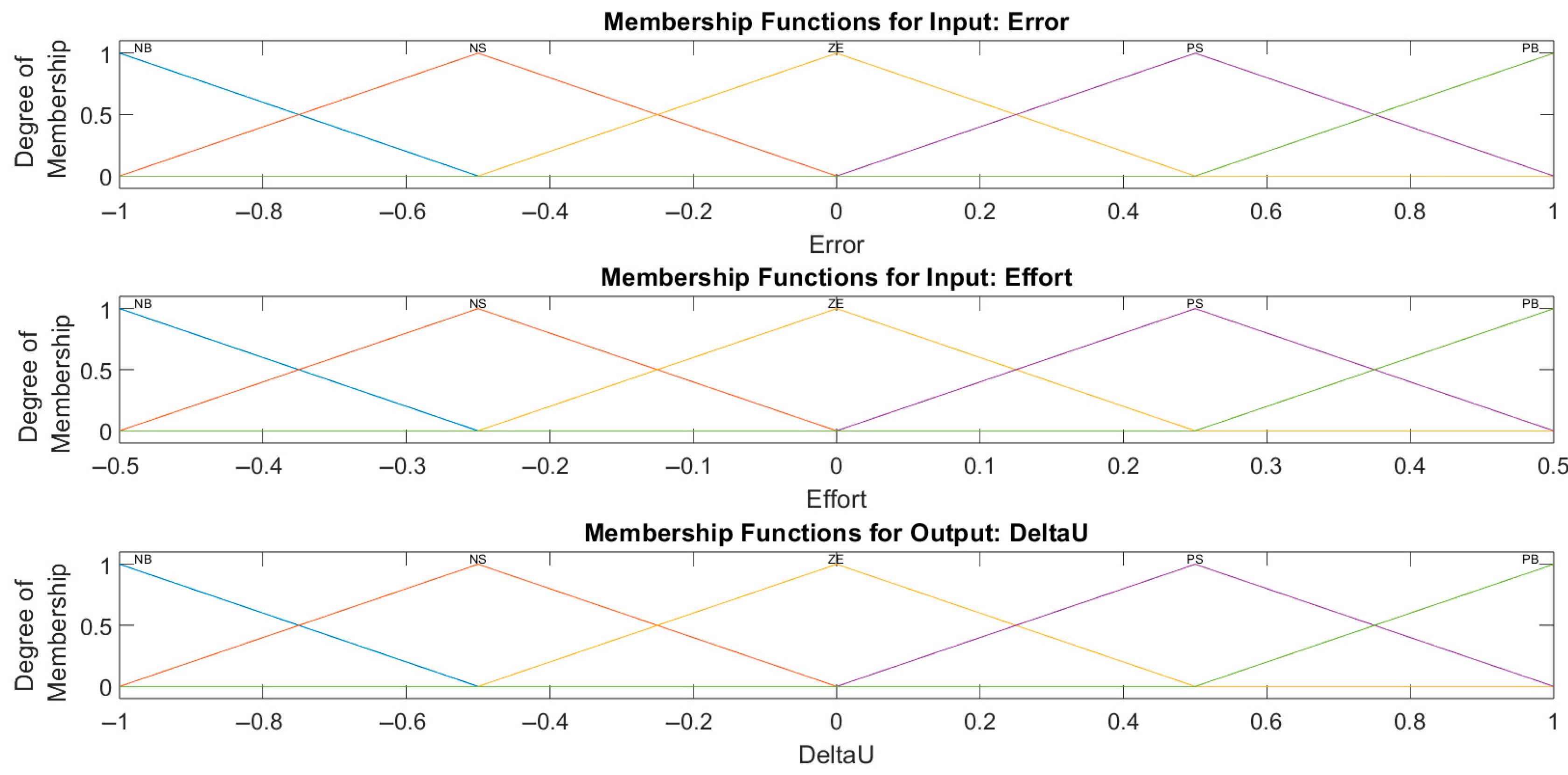
For both the inputs and the output, the same linguistic labels are defined: Negative Big (NB), Negative Small (NS), Zero (ZE), Positive Small (PS), and Positive Big (PB). The universe of discourse for e is [−Emax, Emax], and triangular membership functions are defined as follows:
  • NB: centred at −Emax, with support [−Emax, −Emax/2]
  • NS: centred at −Emax/2, with support [−Emax, 0]
  • ZE: centred at 0, with support [−Emax/2, Emax/2]
  • PS: centred at Emax/2, with support [0, Emax]
  • PB: centred at Emax, with support [Emax/2, Emax]
Similar membership functions are defined for the eeff input, with the specification that the universe of discourse for this input is defined as [−Fmax, Fmax].
The universe of discourse for the output function is defined as [−Umax, Umax], and the membership function uses the following linguistic variables:
  • NB: large negative adjustment.
  • NS: small negative adjustment.
  • ZE: no adjustment.
  • PS: small positive adjustment.
  • PB: large positive adjustment.
The membership function for the input and output functions are presented in Figure 4.
While the membership functions for error, effort, and output shown in Figure 4 appear to be visually similar, each set is defined over a distinct range and physical unit. The tracking error input (e) is measured in radians, typically ranging from –0.2 rad to +0.2 rad, corresponding to joint angle deviations. The estimated effort input (eeff) is derived from encoder torque estimation and ranges from –0.5 Nm to +0.5 Nm, capturing patient-applied torque. The fuzzy controller output (Δu) is a dimensionless control signal used to modulate PID gains and is normalized between –1 and +1 or as specified by a scaling factor U_max.
The choice to use symmetric triangular membership functions with evenly spaced overlap was made to ensure intuitive rule construction, smooth transitions between labels, and real-time computational efficiency. Although this results in similar visual profiles across all variables, the distinct units and ranges ensure that each fuzzy input/output accurately reflects its physical role in the control architecture.
The fuzzy rule base consists of a set of if–then rules that map the combinations of input linguistic labels to an output linguistic label. Rules can be defined to cover the full range of inputs. A common approach is to form a matrix of rules with e along one axis and eeff along the other. The matrix representation of the rules is presented in Table 3. The reading method of the table is presented in the following way: If e is NB and eeff is PS then Δu is NS.
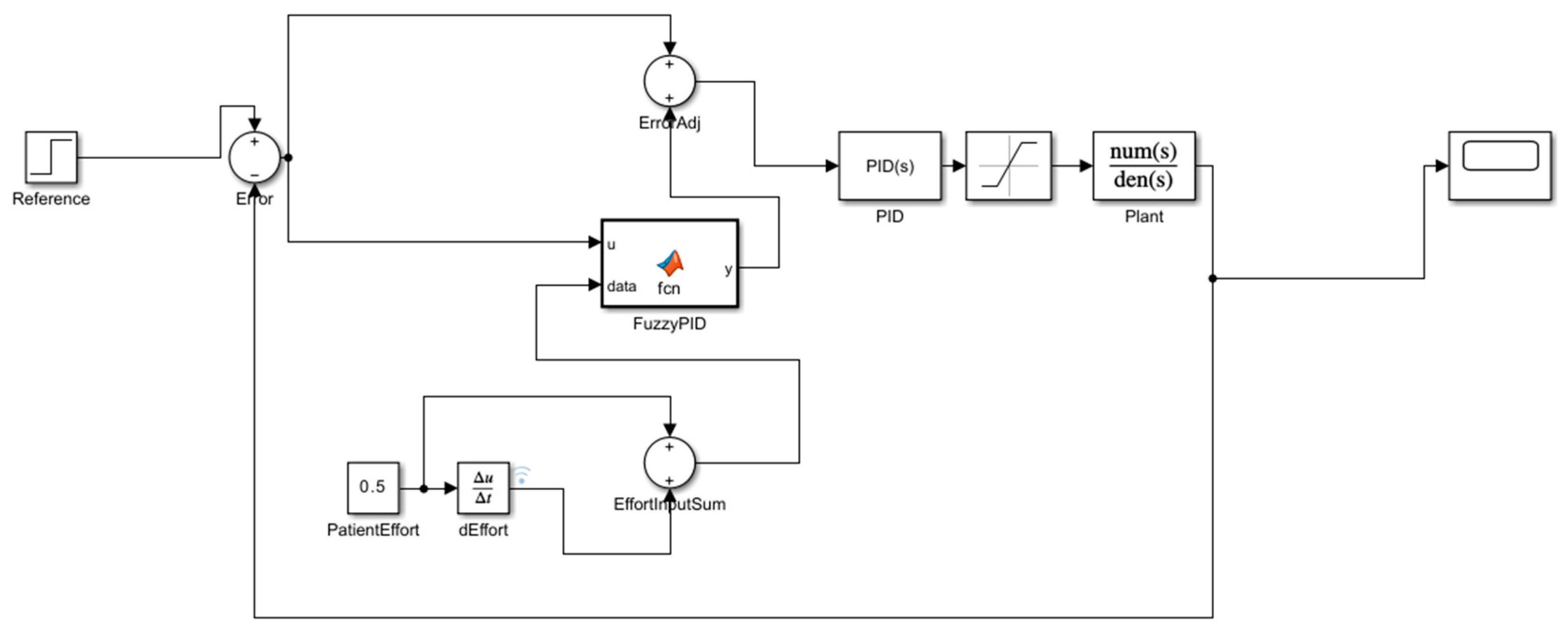
The FIS above is implemented in a Simulink block, which receives the error and the effort signals, processes them according to the defined membership functions and rules, and outputs a control adjustment signal Δu. The output signal is then combined using a Summing block, with the original error before being fed to the PID controller. With respect to previously defined robot–patient interaction modes, 3 FPID controllers are defined. Figure 5 presents the FPID controller for the passive mode, where the fuzzy controller processes the tracking error and outputs an adjustment signal that is summed with the original error before the PID control intervenes. This mode does not require torque monitoring because the motion is performed by the robot. Figure 6 presents the active–assistive mode, where the controller uses additional patient effort information. In this mode, the FIS block processes both the tracking error and the signal representing patient effort. Its output is combined with the tracking error and then fed into the PID controller.
Figure 7 presents the resistive mode where the controller adds an opposing (resistive) signal based on a comparison between a desired resistive torque and the patient’s measured torque. Here, the FIS block processes the torque error signal and outputs resistive adjustment that is subtracted from the overall error before the PID controller intervention.
To transition between rehabilitation modes (passive, active–assistive, and resistive) in real time, an adaptive switching mechanism was implemented based on joint torque estimation. The estimated torque, derived from motor encoder data, serves as a proxy for patient effort during interaction with the rehabilitation robot.
A MATLAB R2024bFunction block titled SelectRehabMode was created in Simulink to classify the current rehabilitation mode based on the magnitude of the estimated torque. The switching logic is driven by two empirically determined thresholds: a lower bound (τ_passive) used to detect patient-initiated motion, and an upper bound (τ_resistive) to indicate sustained voluntary effort requiring resistive training. To prevent rapid mode toggling due to noise or transient fluctuations, a hysteresis band (±τ_hys) was applied around each threshold.
The decision logic follows a finite state paradigm, with three persistent modes:
  • Passive Mode (Mode 1): active when the estimated torque remains below τ_passive. The robot executes pre-programmed trajectories without assistance from the patient.
  • Active–Assistive Mode (Mode 2): triggered when torque exceeds τ_passive + τ_hys, indicating voluntary motion initiation. The robot provides assistive force proportional to patient input.
  • Resistive Mode (Mode 3): engaged when torque exceeds τ_resistive + τ_hys, signaling the ability to handle load-bearing tasks. The controller applies graded resistance to strengthen musculature.
Transitions between modes occur dynamically, based on the torque measurement at each control step. The logic is summarized as follows:
If in Passive and |τ| > τ_passive + hys: switch to Active–Assistive.
If in Active–Assistive:
|τ| > τ_resistive + hys: switch to Resistive
|τ| < τ_passive − hys: revert to Passive
If in Resistive and |τ| < τ_resistive − hys: revert to Active–Assistive
This mechanism allows the system to adapt to the patient’s evolving motor capability during a session, enabling uninterrupted transitions between therapy modes without manual intervention. The controller thus maintains therapeutic relevance throughout the rehabilitation process while minimizing the risk of over- or under-assistance.

3. Results

In order to test the FPID controllers for each interaction mode, equivalent PID controllers were developed without integrating the FIS systems. The conventional PID controller was compared against the developed FPID controller. The comparisons were made across the interaction modes: passive, active–assistive, and resistive.
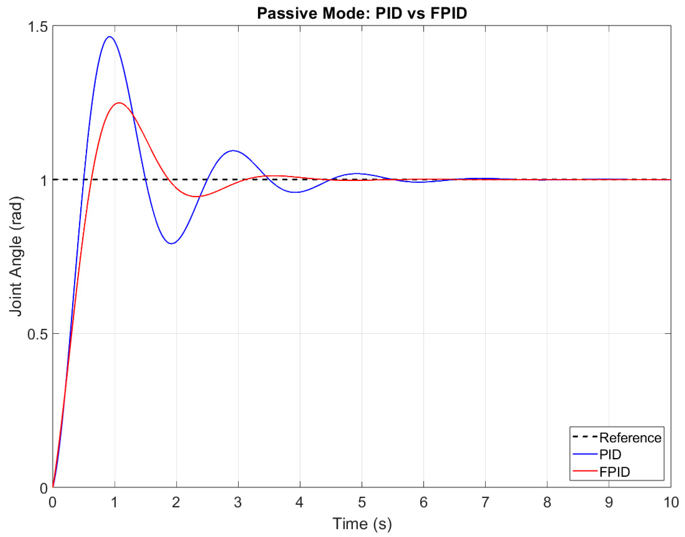
In passive mode, the robot executes a predefined trajectory without relying on patient intervention. The goal is to track the reference trajectory with minimal overshoot and fast settling. Figure 8 below compares the PID and FPID controller responses for the passive mode. For the passive mode, the comparison returned RMSE values of 0.083 for PID and 0.056 for FPID, overshot of 0.107 for PID and 0.065 for FPID, and a settling time of 8.34 s for PID and 6.12 s for FPID, revealing better adaptability of the FPID controller for the passive interaction mode.
In active–assistive mode, the patient initiates movement, and the robot assists in completing the motion. The controller should rapidly correct any lag due to insufficient patient effort. Figure 9 compares the PID and FPID responses when a sinusoidal reference (representing active motion) is tracked. For this comparison, similar results were obtained: RMSE 0.072 (PID), 0.048 (FPID), overshot 0.085 (PID), 0.052 (FPID) and settling time 7.89 s (PID), 6.45 s(FPID). The time response plot shows that the FPID controller tracks the sinusoidal reference more closely, with less lag and a smaller overshoot compared to the conventional PID controller.
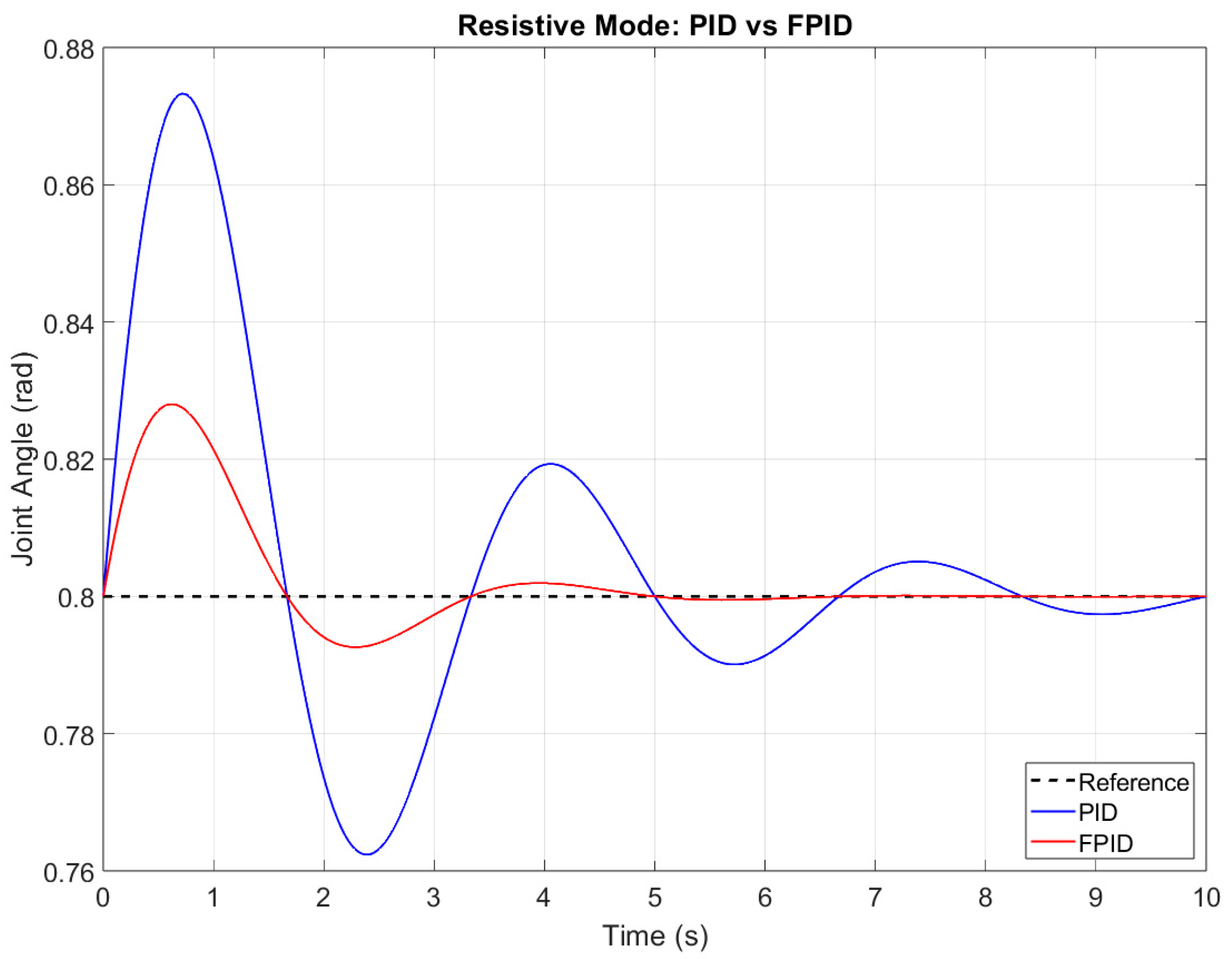
In resistive mode the robot actively opposes the patient’s voluntary motion to build strength. The controller must superimpose a resistive force while still tracking the reference. Figure 10 shows the simulated performance for resistive mode. A constant reference (representing a target joint angle) is imposed, and a resistive disturbance is superimposed. Statistical data are then extracted to evaluate tracking quality under this load. The comparison returned similar results: RMSE 0.072 (PID), 0.051 (FPID), overshoot 0.109 (PID), 0.063 (FPID), and settling time 8.21 s (PID) and 6.75 s (FPID). The results show that the FPID controller is more effective in compensating for the resistive disturbance, as evidenced by lower RMSE, reduced overshoot, and shorter settling time compared to the conventional PID response.
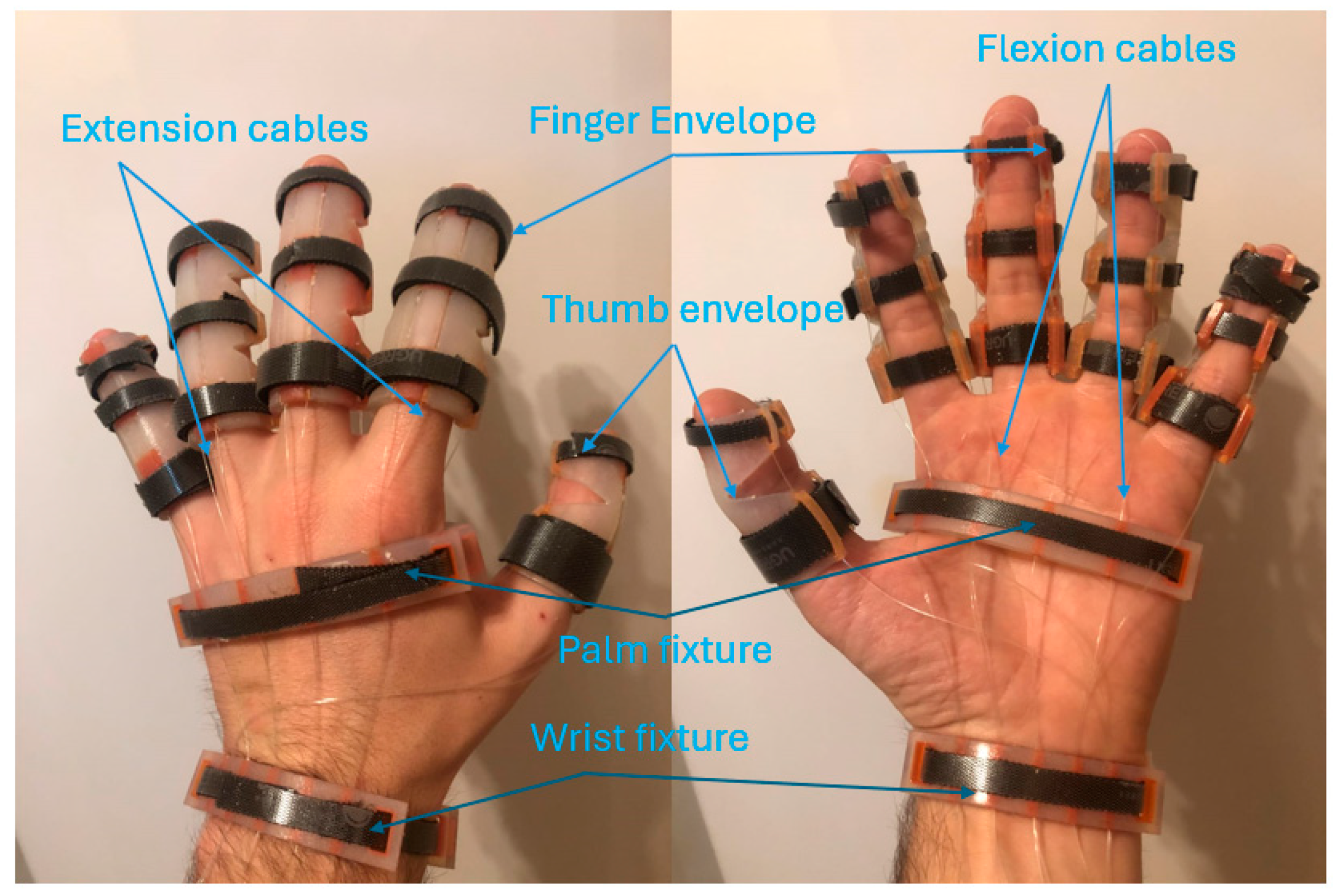
To validate the functional capability of the rehabilitation robot, a composite simulation scenario was designed. In this scenario, a healthy subject performs repeated motion cycles. The prototype of the hand rehabilitation robot is presented in Figure 11.
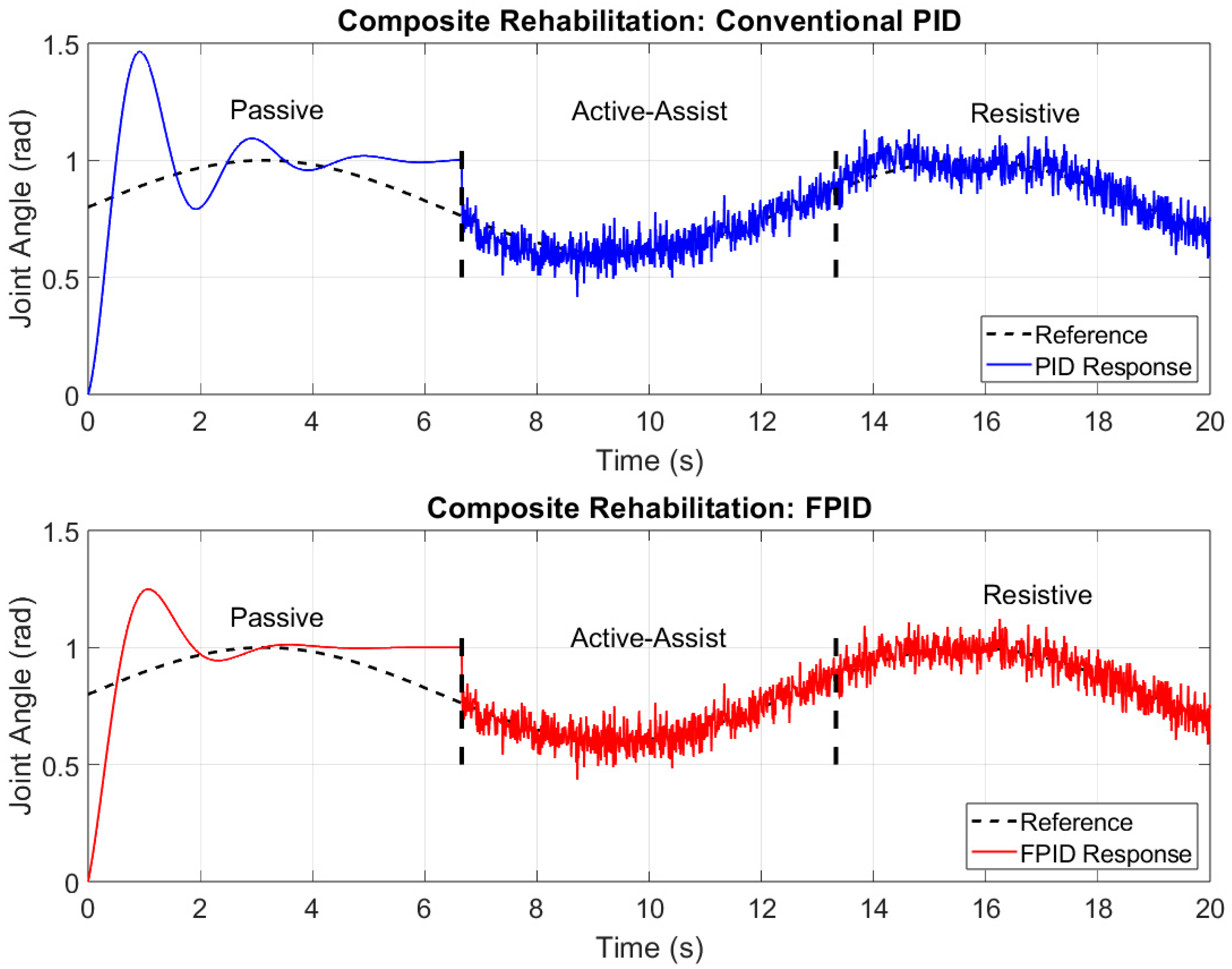
The simulation is segmented into three intervals corresponding to the passive, active–assistive, and resistive modes. Figure 12 illustrates the composite joint angle tracking over 20 s for the conventional PID and the FPID controller, respectively. On each subplot, three time segments are labeled by vertical dashed lines, marking the approximate boundaries between the interaction modes. The “Passive” phase (roughly 0–6 s) is where the robot actively moves the finger through a step-like or gentle motion, with minimal patient input. The “Active–Assist” phase (around 6–12 s) is where the patient is initiating motion, and the device assists in completing it if the patient’s effort is insufficient. The “Resistive” phase (approximately 12–20 s) introduces a controlled opposing force to the patient’s movement, requiring the patient to exert additional effort to maintain the target trajectory. In the top subplot (PID controller), one can see noticeable overshoot during the initial passive phase and higher variability in the active–assist and resistive phases, particularly as the system adapts to the combined effects of patient effort and disturbances. Conversely, the bottom subplot (FPID controller) demonstrates less overshoot in the passive segment, as well as reduced oscillations and deviations during the active–assist and resistive segments. The FPID response appears smoother overall, indicating that the fuzzy logic component helps adapt the control signal to changing conditions—namely, transitions between modes and varying patient input.
From these plots, it is evident that the FPID approach yields improved tracking accuracy and robustness compared to the conventional PID controller, thus underlining the benefits of incorporating fuzzy logic in a rehabilitation robot context.

4. Discussion

The simulation results clearly demonstrate that the fuzzy-PID controller (FPID) outperforms the conventional PID controller across the three defined interaction modes: passive, active–assistive, and resistive.
In passive mode, where the robot performs movements autonomously without requiring patient effort, the FPID controller exhibited a substantial improvement in all key performance metrics. Specifically, it reduced the root mean square error (RMSE) from 0.083 (PID) to 0.056, overshoot from 0.107 rad to 0.065 rad, and settling time from 8.34 s to 6.12 s. These enhancements are critical in a clinical context, where precision in replicating target trajectories ensures safer therapy and minimizes unintended joint stress. The lower overshoot and faster settling further suggest that the FPID’s dynamic gain adjustment contributes to smoother and more controlled joint actuation, preventing abrupt or jerky motions that could cause patient discomfort or anxiety.
In active–assistive mode, where the robot supplements patient-initiated movements, the controller must detect insufficient voluntary input and respond rapidly to provide assistance. The FPID controller again demonstrated superior performance: RMSE was lowered from 0.072 to 0.048, and overshoot dropped from 0.085 rad to 0.052 rad. These improvements were accompanied by a shorter settling time, allowing the robot to adapt more fluidly to the patient’s varying input. This responsiveness is especially important in post-stroke rehabilitation, where motor control is inconsistent and often delayed. The fuzzy logic module within the FPID system allows for real-time assessment of patient effort, ensuring that assistance is proportionally applied—supporting the patient when needed, yet avoiding overcompensation that may reduce patient engagement.
The resistive mode presents a more complex control challenge, as the robot is required to apply controlled resistance to voluntary movement in order to stimulate muscle strengthening. In this scenario, the FPID controller maintained better stability and performance than the conventional PID. The recorded RMSE was 0.051 versus 0.072 for PID, and overshoot was reduced from 0.109 rad to 0.063 rad. The FPID also settled faster (6.75 s vs. 8.21 s). These metrics suggest that the fuzzy logic adaptation enables real-time modulation of resistance forces based on patient input and motion profile, helping ensure safety while delivering effective resistance training. Importantly, the FPID approach avoids the pitfalls of fixed-gain PID controllers, which can fail under the rapidly shifting torque dynamics typical in resistive rehabilitation.
To evaluate system performance under more realistic conditions, a combined rehabilitation scenario was simulated, in which the interaction modes were successively transitioned dynamically. This test aimed to replicate a full therapy session with varying levels of patient involvement and robot assistance. Across all phases—passive, active–assistive, and resistive—the FPID controller maintained better trajectory fidelity, reduced tracking variability, and smoother transitions. The conventional PID controller, in contrast, showed some instability at mode transition points, with higher oscillations and overshoot, highlighting its limited ability to generalize across variable conditions.
From both the technical and clinical perspectives, these results offer credit for the FPID controller in robot-assisted rehabilitation. The controller’s adaptive nature, driven by real-time evaluation of error and patient effort, ensures consistent performance despite nonlinearities, model uncertainties, or patient variability. Such adaptability is crucial for maintaining engagement and safety in therapy sessions, especially in populations with fluctuating motor capacity.
This study reinforces the growing trend toward intelligent control systems in rehabilitation robotics. While various soft robotic gloves and exoskeletons exist for hand rehabilitation [36], few implementations have rigorously compared advanced control strategies under realistic therapy conditions. Moreover, most studies to date involve limited clinical evaluation, with small sample sizes and a lack of protocol standardization [41,42,43,44].
In this context, the presented fuzzy-PID framework contributes a novel, validated control approach that is simulation-proven, adaptable, and immediately implementable in hardware. Complementary to this, recent experimental validations of wearable gloves featuring individualized finger actuation have shown improvements in range of motion and grasping capability [45]. Our future work builds on these foundations, focusing on hardware integration, pilot studies, and clinical trials to assess therapeutic efficacy in stroke patients and other individuals with upper-limb impairment. In our setup, this assessment relies on real-time joint torque data extracted from the motor encoders, providing an efficient and repeatable estimate of patient interaction force. Although more complex bio signals like EMG may offer finer granularity, the encoder-based approach ensures clinical scalability and avoids additional sensor overhead during early-stage deployment
To further contextualize our control strategy, we compared it against representative advanced methods in the literature. Barfi et al. [46] implemented an EMG-driven fuzzy-PI controller for a 15-DOF robotic hand, achieving an average RMSE of 1.61°, significantly better than conventional PI (5.01°). Hu et al. [27] proposed a fuzzy adaptive passive controller that dynamically adjusted assistance based on task performance and impulse—demonstrating enhanced initiative and safety in upper-limb tasks. More recently, Xao et al. [47] reported a DDPG-PID (deep reinforcement learning–augmented PID) applied to a hydraulic servo system, with an RMSE reduction of over 60% compared to fuzzy-PID and rapid convergence. Finally, He et al. [48] employed a SAC-PID (soft actor-critic tunable PID) on hydraulic systems, enabling periodic online tuning and outperforming classical PID in trajectory tracking.
While these strategies demonstrate the power of adaptive and learning-based methods—achieving high accuracy and fast response—they also introduce significant computational complexity and require substantial training or offline setup. In contrast, our fuzzy-PID controller with real-time torque-based mode switching provides a lightweight yet adaptive solution that balances tracking performance (~0.015 rad RMSE, ~4.3% overshoot) with interpretability and suitability for rehabilitation contexts.
While this study demonstrates the feasibility and effectiveness of the FPID controller through extensive simulations and testing on a healthy subject scenario, we acknowledge the limitation that experimental validation on patient populations has not yet been conducted. The use of a healthy subject allowed us to evaluate the system under controlled conditions and ensure safety, consistency, and baseline performance before advancing to real-world deployment. Clinical scenarios present additional challenges, such as irregular patient effort, spasticity, and variability in motor control, to which the controller must adapt. As a continuation of this work, we are actively preparing for hardware integration and pilot clinical trials involving stroke patients and individuals with hand motor impairments. These studies will provide the necessary validation to assess therapeutic efficacy, patient engagement, and safety under actual rehabilitation conditions.
We acknowledge the limitation of this study based on the use of healthy subjects to test the control system, while during patient clinical trials the passing between the interaction modes would not be possible due to the patient state and the motion pattern would not be that regulated. By refining fuzzy logic rule sets and integrating more physiological feedback (e.g., EMG, torque thresholds), we aim to develop a controller that is not only robust but also personalized—supporting patient-specific therapy and further aligning rehabilitation robotics with principles of precision medicine. The FPID may also be integrated with multimodal artificial intelligence agents to adapt to various inputs, such as patient expression, patient state, and integration, with serious gaming based on daily tasks in order to improve the efficiency of the treatment.
While the current fuzzy-PID controller uses manually designed rule sets and gain values tailored to each rehabilitation mode, we recognize that personalization is crucial for maximizing therapeutic outcomes. To that end, future work will explore the use of machine learning techniques such as reinforcement learning (RL) and genetic algorithms (GA) to automatically optimize both the fuzzy inference rules and the PID gain parameters.
These approaches can dynamically tune control strategies based on feedback from: patient-specific joint torque and motion patterns; therapeutic progress indicators (e.g., reduced error, increased voluntary effort); and sensor data trends over time.
In a reinforcement learning framework, the controller could learn optimal control actions through a reward system that penalizes high tracking error and promotes smooth, patient-initiated movement. Alternatively, genetic algorithms could be used offline or in periodic updates to evolve fuzzy rules and PID weights that maximize a defined objective function (e.g., therapy compliance, accuracy, effort).
This would enable a closed-loop adaptation where the control system is not only reactive but also progressively refined according to the patient’s rehabilitation trajectory, enabling precision therapy aligned with individual needs.
Before initiating clinical trials, the authors plan to validate the fuzzy-PID (FPID) controller using a hardware-in-the-loop (HIL) setup. This test bench will integrate the actual robotic hardware with a simulated human hand model and programmable synthetic disturbances. The goal is to assess the real-time performance, safety, and adaptability of the controller under realistic operating conditions.
The HIL setup will include: real-time motor and cable dynamics from the rehabilitation robot; synthetic torque profiles mimicking various patient impairments (e.g., spasticity, flaccidity, reflex bursts); sensor feedback (encoder, torque estimates) processed through the same fuzzy-PID logic; and adaptive mode switching using the torque-based controller.
This platform allows us to emulate unpredictable patient behavior and evaluate control robustness under non-ideal conditions, such as sensor noise, mechanical backlash, or latency. It also serves as a safe intermediary validation step before engaging with clinical populations, ensuring system reliability and responsiveness without patient risk.

5. Conclusions

A fuzzy-PID (FPID) controller for a 4-DOF hand rehabilitation robot was developed and evaluated and compared with a conventional PID controller under passive, active–assistive, and resistive interaction modes. The simulation results showed that the fuzzy-PID (FPID) controller consistently outperformed the conventional PID controller across all defined interaction modes—passive, active–assistive, and resistive—demonstrating superior tracking accuracy, lower RMSE, reduced overshoot, and faster settling times. These findings confirm that the fuzzy-PID controller actively governs the robot’s real-time operation across all therapeutic scenarios. The integration of fuzzy logic into the conventional PID framework has been shown to substantially enhance the robot’s capacity to manage nonlinearities and uncertainties associated with patient variability. By adapting control gains in real time based on instantaneous tracking errors and estimated patient effort, the FPID controller addresses critical limitations of fixed-gain systems, improving both safety and therapeutic efficacy. It is important to note that, although the simulation results are promising, experimental validation with patient populations is a crucial next step. Future work will focus on real-time testing in clinical environments to assess the controller’s adaptability and effectiveness under realistic rehabilitation conditions. The integration of additional physiological feedback, such as electromyographic (EMG) signals, is also planned to improve personalization and support dynamic patient needs. Future work will focus on physical hardware implementation and comprehensive experimental validation, including usability testing, real-time trials on healthy subjects, and pilot clinical trials to evaluate the effectiveness, safety, and patient acceptance of the FPID-controlled rehabilitation robot in real-world healthcare settings. Future development will also explore the integration of richer physiological signals, such as EMG, to complement the current torque-based effort estimation. This would enhance the personalization of therapy while maintaining the scalability and real-time responsiveness demonstrated through motor encoder-based feedback. Additional research will also explore the refinement of fuzzy rule sets and the integration of physiological feedback, such as electromyography (EMG) or bioimpedance, to further personalize control actions and optimize therapeutic impact.

Author Contributions

Conceptualization, P.T., C.V., D.L., B.G., J.M. and D.P.; Formal analysis, O.-M.V., S.S., Z.M. and D.L.; Investigation, P.T., M.C. and S.S.; Methodology, P.T., O.-M.V., D.S., A.P., D.L., S.S., B.G., Z.M., V.B. and I.Z.; Project administration, C.V., J.M. and D.P.; Resources, I.Z., M.C. and J.M.; Software, P.T., C.V., D.S., A.P., S.S., B.G., V.B. and I.Z.; Supervision, C.V., A.P., J.M. and D.P.; Validation, O.-M.V., Z.M. and D.P.; Visualization, M.C. and D.P.; Writing—original draft, P.T. and B.G. Writing-review and editing, P.T., O.-M.V., C.V., M.C., D.S., A.P., S.S., D.L., Z.M., B.G., V.B., I.Z., J.M. and D.P. All authors have read and agreed to the published version of the manuscript.

Funding

This research has been supported by the project New frontiers in adaptive modular robotics for patient-centered medical rehabilitation—ASKLEPIOS, funded by European Union—Next Generation EU and Romanian Government, under the National Recovery and Resilience Plan for Romania, contract no. 760071/23.05.2023, code CF 121/15.11.2022, with the Romanian Ministry of Research, Innovation and Digitalization, within Component 9, investment I8.

Institutional Review Board Statement

Ethical review and approval were waived for this study due to the fact that the study involved healthy subject, was non-invasive and the subject signed informed consent.

Informed Consent Statement

Informed consent for participation was obtained from all subjects involved in the study.

Data Availability Statement

The data presented in this study are available upon request from the corresponding author.

Conflicts of Interest

The authors declare no conflicts of interest.

References

  1. Kamper, D.G.; Fischer, H.C.; Cruz, E.G.; Rymer, W.Z. Weakness Is the Primary Contributor to Finger Impairment in Chronic Stroke. Arch. Phys. Med. Rehabil. 2006, 87, 1262–1269. [Google Scholar] [CrossRef] [PubMed]
  2. Bonzano, L.; Sormani, M.P.; Tacchino, A.; Abate, L.; Lappuci, C.; Mancardi, G.L.; Uccelli, A. Bove, Marco, Quantitative Assessment of Finger Motor Impairment in Multiple Sclersosis. PLoS ONE 2013, 8, e65225. [Google Scholar] [CrossRef] [PubMed]
  3. Anwer, S.; Waris, A.; Gilani, S.O.; Iqbal, J.; Shaikh, N.; Pujari, A.N.; Niazi, I.K. Rehabilitation of Upper Limb Motor Impairment in Stroke: A Narrative Review on the Prevalence, Risk Factors, and Economic Statistics of Stroke and State of the Art Therapies. Healthcare 2022, 10, 190. [Google Scholar] [CrossRef] [PubMed]
  4. Dalton, E.J.; Jamwal, R.; Augoustakis, L.; Hill, E.; Johns, H.; Thijs, V.; Hayward, K.S. Prevalence of Arm Weakness, Pre-Stroke Outcomes and Other Post-Stroke Impairments Using Routinely Collected Clinical Data on an Acute Stroke Unit. Neurorehabilit. Neural Repair 2024, 38, 148–160. [Google Scholar] [CrossRef] [PubMed]
  5. Saito, T.; Nakamichi, R.; Nakahara, R.; Nishida, K.; Ozaki, T. The Effectiveness of Rehabilitation after Open Surgical Release for Trigger Finger: A Prospective, Randomized, Controlled Study. J. Clin. Med. 2023, 12, 7187. [Google Scholar] [CrossRef] [PubMed]
  6. Waszczykowski, M.; Dziankowska-Bartkowiak, B.; Podgórski, M.; Fabis, J.; Waszczykowski, A. Role and effectiveness of complex and supervised rehabilitation on overall and hand function in systemic sclerosis patients—One-year follow-up study. Sci. Rep. 2021, 11, 15174. [Google Scholar] [CrossRef] [PubMed]
  7. Landry, M.D.; Hack, L.M.; Coulson, E.; Freburger, J.; Johnson, M.P.; Katz, R.; Kerwin, J.; Smith, M.H.; “Bud” Wessman, H.C.; Venskus, D.G.; et al. Workforce Projections 2010–2020: Annual Supply and Demand Forecasting Models for Physical Therapists Across the United States. Phys. Ther. 2016, 96, 71–80. [Google Scholar] [CrossRef] [PubMed]
  8. Leonardis, D.; Barsotti, M.; Loconsole, C.; Solazzi, M.; Troncossi, M.; Mazzotti, C.; Castelli, V.P.; Procopio, C.; Lamola, G.; Lamola, C.; et al. An EMG-Controlled robotic hand exoskeleton for bilateral rehabilitation. IEEE Trans. Haptics 2015, 8, 140–151. [Google Scholar] [CrossRef] [PubMed]
  9. Gherman, B.; Zima, I.; Vaida, C.; Tucan, P.; Pisla, A.; Birlescu, I.; Machado, J.; Pisla, D. Robotic Systems for Hand Rehabilitation—Past, Present and Future. Technologies 2025, 13, 37. [Google Scholar] [CrossRef]
  10. Ratz, R.; Conti, F.; Muri, R.M.; Marchal-Crespo, L. A Novel Clinical-Driven Design for Robotic Hand Rehabilitation: Combining Sensory Training, Effortless Setup, and Large Range of Motion in a Palmar Device. Front. Neurorobotics 2021, 15, 748196. [Google Scholar] [CrossRef] [PubMed]
  11. Mahfouz, D.M.; Shehata, O.M.; Morgan, E.I.; Arrichiello, F. A Comprehensive Review of Control Challenges and Methods in End-Effector Upper-Limb Rehabilitation Robots. Robotics 2024, 13, 181. [Google Scholar] [CrossRef]
  12. Li, X.; Peng, Y.; Chen, Z. Review of Adaptive Control for Stroke Lower Limb Exoskeleton Rehabilitation Robots. Front. Neurorobotics 2023, 17, 1186175. [Google Scholar] [CrossRef] [PubMed]
  13. Baud, R.; Manzoori, A.R.; Ijspeert, A.; Bouri, M. Review of Control Strategies for Lower-Limb Exoskeletons to Assist Gait. J. Neuroeng. Rehabil. 2021, 18, 119. [Google Scholar] [CrossRef] [PubMed]
  14. Ghafoori, S.; Rabiee, A.; Norouzi, M.; Jouaneh, M.; Abiri, R. A Novel Seamless Magnetic-Based Actuating Mechanism for End-Effector-Based Robotic Rehabilitation Platforms. arXiv 2024, arXiv:2404.01441. [Google Scholar] [CrossRef]
  15. Zhang, Y.; Li, S.; Nolan, K.J.; Zanotto, D. Shaping Individualized Impedance Landscapes for Gait Training via Reinforcement Learning. arXiv 2021, arXiv:2109.02109. [Google Scholar] [CrossRef]
  16. Wang, H.; Shen, H.; Han, Y.; Zhou, W.; Wang, J. Effect of Robot-Assisted Training for Lower Limb Rehabilitation on Lower Limb Function in Stroke Patients: A Systematic Review and Meta-Analysis. Front. Hum. Neurosci. 2025, 19, 1549379. [Google Scholar] [CrossRef] [PubMed]
  17. Khan, M.U.A.; Ajmal, H.M.S.; Hassan, H.A.; Azam, A.; Malik, E. A Soft Robotic Sleeve for Physiotherapy: Improving Elbow Rehabilitation in Baseball Pitchers. Physiother. Res. Int. 2025, 30, e70025. [Google Scholar] [CrossRef] [PubMed]
  18. Pezeshki, L.; Sadeghian, H.; Mohebbi, A.; Keshmiri, M.; Haddadin, S. Personalized Assistance in Robotic Rehabilitation: Real-Time Adaptation via Energy-Based Performance Monitoring. IEEE Trans. Autom. Sci. Eng. 2025, 22, 1234–1245. [Google Scholar] [CrossRef]
  19. Lejeune, T.; Nuic, D.; Dehem, S.; Previnaire, J.-G.; Cuenot, C.; Debugne, T.; Kaps, J.; Paul, B.; Pean, V.; Sanz Perez, S.; et al. Hands-Free Atalante Exoskeleton in Post-Stroke Gait and Balance Rehabilitation: A Safety Study. J. Neuroeng. Rehabil. 2025, 22, 82. [Google Scholar] [CrossRef] [PubMed]
  20. Duanmu, D.; Wen, R.; Li, X.; Huang, W.; Hu, Y. Development of Assistive Donning Device of Robotic Hand Glove Inspired by the Venus Flytrap. Mech. Based Des. Struct. Mach. 2025, 53, 2487171. [Google Scholar] [CrossRef]
  21. Roy, R.; Islam, M.; Rashid, M.; Mounis, S.; Ahsan, M.M.; Ahad, M.T.; Siddique, Z.; Kouzani, A.Z.; Mahmud, M.A.P. Investigation of 2DOF PID Controller for Physio-Therapeutic Application for Elbow Rehabilitation. Appl. Sci. 2021, 11, 8617. [Google Scholar] [CrossRef]
  22. Saleem, O.; Ahmad, K.R.; Iqbal, J. Fuzzy-Augmented Model Reference Adaptive PID Control Law Design for Robust Voltage Regulation in DC–DC Buck Converters. Mathematics 2024, 12, 1893. [Google Scholar] [CrossRef]
  23. Maxim, A.; Pauca, O.; Caruntu, C.-F. Distributed Model Predictive Control and Coalitional Control Strategies—Comparative Performance Analysis Using an Eight-Tank Process Case Study. Actuators 2023, 12, 281. [Google Scholar] [CrossRef]
  24. Xiao, W.; Chen, K.; Fan, J.; Hou, Y.; Kong, W.; Dan, G. AI-driven rehabilitation and assistive robotic system with intelligent PID controller based on RBF neural networks. Neural Comput. Appl. 2023, 35, 16021–16035. [Google Scholar] [CrossRef]
  25. Borase, R.P.; Maghade, D.K.; Sondkar, S.Y.; Pawar, S.N. A Review of PID Control, Tuning Methods and Applications. Int. J. Dyn. Control 2021, 9, 818–827. [Google Scholar] [CrossRef]
  26. Tong, L.; Cui, D.; Wang, C.; Peng, L. A Novel Zero-Force Control Framework for Post-Stroke Rehabilitation Training Based on Fuzzy-PID Method. Intell. Robot. 2024, 4, 125–145. [Google Scholar] [CrossRef]
  27. Hu, Y.; Meng, J.; Li, G.; Zhao, D.; Feng, G.; Zuo, G.; Liu, Y.; Zhang, J.; Shi, C. Fuzzy Adaptive Passive Control Strategy Design for Upper-Limb End-Effector Rehabilitation Robot. Sensors 2023, 23, 4042. [Google Scholar] [CrossRef] [PubMed]
  28. Jin, X.; Guo, J. Disturbance Rejection Model Predictive Control of Lower Limb Rehabilitation Exoskeleton. Sci. Rep. 2023, 13, 19463. [Google Scholar] [CrossRef] [PubMed]
  29. Yan, Y.; Tang, M.; Wang, W.; Zhang, Y.; An, B. Trajectory Tracking Control of Wearable Upper Limb Rehabilitation Robot Based on Laguerre Model Predictive Control. Robot. Auton. Syst. 2024, 179, 104745. [Google Scholar] [CrossRef]
  30. Brown, D.F.; Xie, S.Q. Model Predictive Control with Optimal Modelling for Pneumatic Artificial Muscle in Rehabilitation Robotics: Confirmation of Validity Though Preliminary Testing. Biomimetics 2025, 10, 208. [Google Scholar] [CrossRef] [PubMed]
  31. Geonea, I.D.; Tarnita, D.; Pisla, D.; Carbone, G.; Bolcu, A.; Tucan, P.; Georgescu, M.; Tarniță, D.N. Dynamic Analysis of a Spherical Parallel Robot Used for Brachial Monoparesis Rehabilitation. Appl. Sci. 2021, 11, 11849. [Google Scholar] [CrossRef]
  32. Lou, Y.; Lin, H.; Quan, P.; Wei, D.; Di, S. Robust Adaptive Control of Fully Constrained Cable-Driven Serial Manipulator with Multi-Segment Cables Using Cable Tension Sensor Measurements. Sensors 2021, 21, 1623. [Google Scholar] [CrossRef] [PubMed]
  33. Chen, W.; Li, Z.; Cui, X.; Zhang, J.; Bai, S. Mechanical Design and Kinematic Modeling of a Cable-Driven Arm Exoskeleton Incorporating Inaccurate Human Limb Anthropomorphic Parameters. Sensors 2019, 19, 4461. [Google Scholar] [CrossRef] [PubMed]
  34. Vaida, C.; Birlescu, I.; Pîșla, A.; Carbone, G.; Plitea, N.; Ulinici, I.; Gherman, B.; Puskas, F.; Tucan, P.; Pîșla, D. RAISE—An Innovative Parallel Robotic System for Lower Limb Rehabilitation. In New Trends in Medical and Service Robotics; Carbone, G., Ceccarelli, M., Pîșla, D., Eds.; Mechanisms and Machine Science; Springer: Cham, Switzerland, 2018; pp. 293–302. [Google Scholar]
  35. Vaida, C.; Plitea, N.; Carbone, G.; Birlescu, I.; Ulinici, I.; Pîșla, A.; Pîșla, D. Innovative development of a spherical parallel robot for upper limb rehabilitation. Int. J. Mech. Robot. Syst. 2018, 4, 256. [Google Scholar] [CrossRef]
  36. Fardipour, S.; Hadadi, M. Investigation of Therapeutic Effects of Wearable Robotic Gloves on Improving Hand Function in Stroke Patients: A Systematic Review. Curr. J. Neurol. 2022, 21, 125–132. [Google Scholar] [CrossRef] [PubMed]
  37. Peng, Y.; Yang, X.; Li, D.; Ma, Z.; Liu, Z.; Bai, X.; Mao, Z. Predicting flow status of a flexible rectifier using cognitive computing. Expert Syst. Appl. 2025, 264, 125878. [Google Scholar] [CrossRef]
  38. Mao, Z.; Kobayashi, R.; Nabae, H.; Suzumori, K. Multimodal Strain Sensing System for Shape Recognition of Tensegrity Structures by Combining Traditional Regression and Deep Learning Approaches. IEEE Robot. Autom. Lett. 2024, 9, 10050–10056. [Google Scholar] [CrossRef]
  39. Birouaș, F.I.; Țarcă, R.C.; Dzitac, S.; Dzitac, I. Preliminary Results in Testing of a Novel Asymmetric Underactuated Robotic Hand Exoskeleton for Motor Impairment Rehabilitation. Symmetry 2020, 12, 1470. [Google Scholar] [CrossRef]
  40. Tohanean, N.; Tucan, P.; Vanta, O.-M.; Abrudan, C.; Pintea, S.; Gherman, B.; Burz, A.; Banica, A.; Vaida, C.; Neguran, D.A.; et al. The Efficacity of the NeuroAssist Robotic System for Motor Rehabilitation of the Upper Limb—Promising Results from a Pilot Study. J. Clin. Med. 2023, 12, 425. [Google Scholar] [CrossRef] [PubMed]
  41. Connelly, L.; Stoykov, M.E.; Jia, Y.; Toro, M.L.; Kenyon, R.V.; Kamper, D.G. Use of a pneumatic glove for hand rehabilitation following stroke. In Proceedings of the Annual International Conference of the IEEE Engineering in Medicine and Biology Society, Minneapolis, MN, USA, 3–6 September 2009; pp. 2434–2437. [Google Scholar] [CrossRef]
  42. Fischer, H.C.; Triandafilou, K.M.; Thielbar, K.O.; Ochoa, J.M.; Lazzaro, E.D.; Pacholski, K.A.; Kamper, D.G. Use of a portable assistive glove to facilitate rehabilitation in stroke survivors with severe hand impairment. IEEE Trans. Neural Syst. Rehabil. Eng. 2016, 24, 344–351. [Google Scholar] [CrossRef] [PubMed]
  43. van Ommeren, A.L.; Radder, B.; Buurke, J.H.; Kottink, I.R.; Holmberg, J.; Sletta, K.; Prange-Lasonder, G.B.; Rietman, J.S. The effect of prolonged use of a wearable soft-robotic glove post stroke—A proof-of-principle. In Proceedings of the 7th IEEE International Conference on Biomedical Robotics and Biomechatronics (BioRob), Enschede, The Netherlands, 26–29 August 2018. [Google Scholar]
  44. Prange-Lasonder, G.B.; Radder, B.; Kottink, A.I.R.; Melendez-Calderon, A.; Buurke, J.H.; Rietman, J.S. Applying a soft-robotic glove as assistive device and training tool with games to support hand function after stroke: Preliminary results on feasibility and potential clinical impact. In Proceedings of the IEEE International Conference on Rehabilitation Robotics (ICORR), London, UK, 17–20 July 2017; pp. 1401–1406. [Google Scholar] [CrossRef]
  45. Zhu, Y.; Gong, W.; Chu, K.; Wang, X.; Hu, Z.; Su, H. A Novel Wearable Soft Glove for Hand Rehabilitation and Assistive Grasping. Sensors 2022, 22, 6294. [Google Scholar] [CrossRef] [PubMed]
  46. Barfi, M.; Karami, H.; Faridi, F.; Sohrabi, Z.; Hosseini, M. Improving robotic hand control via adaptive Fuzzy-PI controller using classification of EMG signals. Heliyon 2022, 8, e11931. [Google Scholar] [CrossRef] [PubMed]
  47. Hao, X.; Xin, Z.; Huang, W.; Wan, S.; Qiu, G.; Wang, T.; Wang, Z. Deep reinforcement learning enhanced PID control for hydraulic servo systems in injection molding machines. Sci. Rep. 2025, 15, 23005. [Google Scholar] [CrossRef] [PubMed]
  48. He, J.; Su, S.; Wang, H.; Chen, F.; Yin, B. Online PID Tuning Strategy for Hydraulic Servo Control Systems via SAC-Based Deep Reinforcement Learning. Machines 2023, 11, 593. [Google Scholar] [CrossRef]
Figure 1. Joints and lengths of fingers and thumb.
Actuators 14 00351 g001
Figure 2. The concept of the cable-actuated finger rehabilitation robot.
Actuators 14 00351 g002
Figure 3. Detail of the finger envelope (index finger).
Actuators 14 00351 g003
Figure 4. Membership functions for input and output functions.
Actuators 14 00351 g004
Figure 5. Passive FPID model.
Actuators 14 00351 g005
Figure 6. Active–Assistive FPID model.
Actuators 14 00351 g006
Figure 7. Resistive FPID model.
Actuators 14 00351 g007
Figure 8. FPID vs. PID for the passive interaction mode.
Actuators 14 00351 g008
Figure 9. PID vs. FPID in Active–assistive interaction mode.
Actuators 14 00351 g009
Figure 10. PID vs. FPID in resistive mode.
Actuators 14 00351 g010
Figure 11. Prototype of the hand rehabilitation robot.
Actuators 14 00351 g011
Figure 12. Complex simulation of the two controllers.
Actuators 14 00351 g012
Table 1. Robotic-assisted protocol for hand rehabilitation.
Protocol ParameterPRAIMPAARIMPRSRIMP
Sessions15–20 min per session, 3–5 sessions per week.15–20 min per session, 3–5 sessions per week.15–20 min per session, 3–5 sessions per week.
Repetitions2–3 sets of 10–15 repetitions per movement cycle.2–3 sets of 10–15 repetitions per movement cycle.3 sets of 10–15 repetitions per movement cycle, focusing on gradually increasing resistance.
Motion executionThe robotic system moves the fingers through predefined arcs while maintaining joint safety. Also maintains the stretch for 2 s to preserve ROM.The patient initiates movement while the robotic device provides adjustable assistance based on the detected effort.The device now introduces graded resistance to challenge the patient’s muscles during active movement.
MCP JointPassive flexion up to 80–90° and extension to neutral (0–10°).Aim for active movement toward 80–90° flexion (with assistance) and controlled return to neutral.Active movement against resistance, targeting the same arc (flexion up to 80–90° and return to neutral) with emphasis on strength.
PIP JointFlexion up to 90–100° and extension to 0–10°Active-assisted flexion targeting 90–100° with gradual extension to 0–10°.Active flexion toward 90–100° with resistance, ensuring controlled extension to 0–10°.
DIP JointFlexion up to 60–70°.Active-assisted flexion approaching 60–70°, progressing toward independent control.Active flexion of 60–70° with resistance to build fine motor control and muscular endurance.
ThumbOppositional movements: Guide the thumb in abduction and opposition, aiming for contact with the small finger (approximating a 50° opposition angle).Assisted opposition and abduction to achieve a 50° opposition angle, reinforcing the initiation of thumb-to-small finger contact.Resistance-based opposition and abduction training to reinforce a 50° opposition angle, promoting strength and fine control.
MonitoringMonitor for discomfort or signs of increased spasticity. Adjust the device’s speed and range if any pain or discomfort is reported.Closely monitor the patient’s initiation effort, movement smoothness, and any discomfort; adjust the level of robotic assistance as needed to ensure safety.Monitor for signs of fatigue, discomfort, or improper technique; adjust resistance levels and provide feedback to maintain proper movement quality.
Table 2. Notation of geometric parameters.
NotationDescription
θ1MCP angle
θ1PIP angle
θ1DIP angle
L11length from MCP to PIP
L12length from PIP to DIP
L13length from DIP to fingertip
q1finger extension active joint
q2finger flexion active joint
LMCPfrom cable tensioner 1 and 2 to finger MCP
α1CMC angle
α2MP angle
α3IP angle
L21length from CMC to MP
L22length from MP to IP
L23length from IP to thumb tip
q3thumb extension active joint
q4thumb flexion active joint
LMPlength from cable tensioner to MP
Dpulley diameter
Table 3. The FIS Rules.
e/eeffNBNSZEPSPB
NBNBNBNBNSZE
NSNBNBNSZEPS
ZENBNSZEPSPB
PSNSZEPSPBPB
PBZEPSPBPBPB
Disclaimer/Publisher’s Note: The statements, opinions and data contained in all publications are solely those of the individual author(s) and contributor(s) and not of MDPI and/or the editor(s). MDPI and/or the editor(s) disclaim responsibility for any injury to people or property resulting from any ideas, methods, instructions or products referred to in the content.