Article

Research on Active Disturbance Rejection Control of Rigid–Flexible Coupled Constant Force Actuator

1
State Key Laboratory for Precision Electronics Manufacturing, Guangdong University of Technology, Guangzhou 510006, China
2
Foshan Huadao Ultra Precision Tech. Ltd., Foshan 528244, China
*
Author to whom correspondence should be addressed.
These authors contributed equally to this work.
Actuators 2025, 14(7), 325; https://doi.org/10.3390/act14070325
Submission received: 25 May 2025 / Revised: 21 June 2025 / Accepted: 27 June 2025 / Published: 30 June 2025
(This article belongs to the Section Control Systems)

Abstract

This study introduces a rigid–flexible coupled constant force actuator integrated with Active Disturbance Rejection Control (ADRC) to tackle the rigidity–compliance trade-off in precision force-sensitive applications. The actuator utilizes compliant hinges to decrease contact stiffness by three orders of magnitude ( 10 6 10 3   N / m ), facilitating effective force management through millimeter-scale placement (0.1∼1 mm) and inherently mitigating high-frequency disturbances. The ADRC framework, augmented by an Extended State Observer (ESO), dynamically assesses and compensates for internal nonlinearities (such as friction hysteresis) and external disturbances without necessitating accurate system models. Experimental results indicate enhanced performance compared to PID control: under dynamic disturbances, force deviations are limited to ± 0.2   N with a 98.5% reduction in mean absolute error, a 96.3% increase in settling speed, and 99% suppression of oscillations. The co-design of mechanical compliance with model-free control addresses the constraints of traditional high-stiffness systems, providing a scalable solution for industrial robots, compliant material processing, and medical device operations. Validation of the prototype under sinusoidal perturbations demonstrates reliable force regulation (settling time < 0.56   s , errors < 0.5   N ), underscoring its relevance in dynamic situations. This study integrates theoretical innovation with experimental precision, enhancing intelligent manufacturing systems via adaptive control and structural synergy.

1. Introduction

Robotic polishing and grinding have emerged as essential technologies in high-precision production, facilitating automated surface finishing for critical applications in the automotive, aerospace, and medical device industries [1,2]. While these systems enhance repeatability and save labor costs through programmed route planning, their efficacy is fundamentally constrained by challenges in maintaining a consistent tool–workpiece contact force, particularly when working with materials with intricate geometries or fluctuating dimensional tolerances [3,4]. Conventional stiff actuators are excessively sensitive to displacement errors and external disturbances, making achieving steady constant force control under dynamic perturbations a persistent problem.
The development of force-controlled systems has evolved significantly over several decades, transitioning from basic pneumatic mechanisms to advanced electric servo-driven architectures like series elastic actuator [5,6], collaborative robot [7,8], and wheel-legged robot [9,10,11]. Contemporary implementations frequently incorporate multi-sensor fusion methodologies, combining force and torque measurements with inertial feedback mechanisms to enhance the stabilization of tool–workpiece interactions [12,13,14]. Despite the aforementioned advancements, structural limitations such as high contact stiffness and limited control bandwidth continue to impede the accuracy of force regulation. This is especially evident in applications that require real-time adaptation to environmental uncertainties [15,16,17]. Recent investigations aimed at augmenting the precision of force control have concentrated on two principal actuator design paradigms: the optimization of kinematics to minimize moving inertia [18,19] and the implementation of parallel mechanisms to enhance dynamic decoupling [20,21,22]. Nevertheless, both methodologies are constrained by their dependence on rigid-body assumptions and linear control paradigms, which fundamentally limit their ability to reject disturbances [23,24,25].
Within the context of control strategies, conventional methodologies such as impedance/admittance control [12,26,27], adaptive control [28,29], and hybrid force/position control [30,31] have demonstrated efficacy in specific scenarios. However, the effectiveness of these methods significantly declines when applied to systems with nonlinear dynamics or variable environmental conditions. This limitation arises from the necessity for accurate system modeling and the inability to respond to transient disturbances effectively [32,33]. Active Disturbance Rejection Control (ADRC) effectively overcomes these limitations by employing a distinctive model-independent framework. This approach facilitates the dynamic estimation and compensation for both internal uncertainties and external disturbances through the utilization of an Extended State Observer (ESO) [17,34]. The integration of compliant mechanisms with advanced control algorithms has attracted interest, offering inherent vibration damping and enhanced adaptability to environmental changes [14,35,36]. Rigid–flexible coupled systems exhibit considerable potential in attaining a balance between structural rigidity and localized compliance. This feature enables real-time disturbance detection while preserving motion precision [34,37,38]. Recent developments in the industry demonstrate the significant advantages of integrating mechanical compliance with model-free control methods to achieve multi-objective force regulation [37,39].
This paper presents a novel rigid–flexible coupled constant force control architecture that integrates two synergistic innovations to address the limitations of conventional high-stiffness systems [40,41]. First, the proposed actuator design introduces compliant hinges between rigid subsystems, reducing contact stiffness by three orders of magnitude. This structural innovation fundamentally decouples force regulation from ultra-precise positioning requirements, enabling robust force control through millimeter-scale elastic deformation rather than micron-level adjustments. The compliant interface inherently attenuates high-frequency disturbances while preserving structural integrity in primary motion axes, thereby mitigating sensitivity to environmental uncertainties. Second, the integration of Active Disturbance Rejection Control (ADRC) establishes a model-free control framework that dynamically estimates and compensates for both internal nonlinearities (e.g., friction hysteresis) and external perturbations (e.g., workpiece vibrations). Unlike conventional PID strategies, which rely on fixed gains and accurate system models, the Extended State Observer (ESO) embedded in ADRC provides real-time adaptability to dynamic disturbances. This co-design philosophy bridges the gap between mechanical compliance and control sophistication, achieving dual objectives: high-precision motion through rigid-body kinematics and enhanced disturbance rejection through localized flexibility. The combined framework offers a transformative solution for industrial applications demanding both precision and robustness in force-sensitive operations. This work makes the following key contributions:
  • Decoupled Rigid–Flexible Actuator Design: A hybrid rigid–flexible coupled structure employs compliant hinges to reduce contact stiffness by three orders of magnitude. This enables force regulation via millimeter-scale elastic deformation instead of micron-level positioning, inherently attenuating high-frequency disturbances while reducing displacement sensitivity.
  • ADRC-ESO Co-Design for Robust Force Control: Tight integration of Active Disturbance Rejection Control (ADRC) with the compliant actuator facilitates real-time estimation and compensation of dynamic disturbances (e.g., friction hysteresis, workpiece vibrations) through an Extended State Observer (ESO), eliminating dependency on precise system models. This co-design bridges mechanical compliance with control sophistication, achieving simultaneous high-precision motion and disturbance-robust force regulation.
The remainder of this paper is organized as follows: Section 2 details the mechanical design and dynamic modeling of the rigid–flexible coupled actuator. Section 3 presents the ADRC controller architecture, emphasizing ESO implementation and parameter tuning. Section 4 describes the experimental setup and comparative results between ADRC and PID control strategies. Finally, Section 5 discusses practical implications and suggests future research directions.

2. Rigid–Flexible Coupled Constant Force Actuator: Principle and Advantages

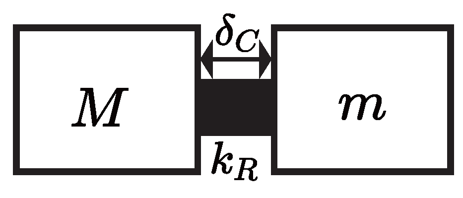
2.1. Limitations of Traditional Rigid Contact Models

In traditional constant force control frameworks (depicted in Figure 1), the interaction between the output force head (designated as M) and the contact object (m) is generally represented as a rigid contact mechanism. The contact force F C is determined by
F C = k R   ·   δ C
where k R indicates the contact stiffness (often exceeding 10 6 N/m), and δ C indicates the contact displacement. To attain accurate force management, the system must rectify force discrepancies via micron-level modifications of δ C . This establishes rigorous demands for positional precision (often <1 μ m ) and intensifies susceptibility to external perturbations. A slight disturbance-induced displacement Δ δ C (e.g., 0.5 μ m) would result in substantial force fluctuations Δ F C = k R   ·   Δ δ C (surpassing 0.5 N when k R = 1 × 10 6 N/m), significantly compromising force stability.

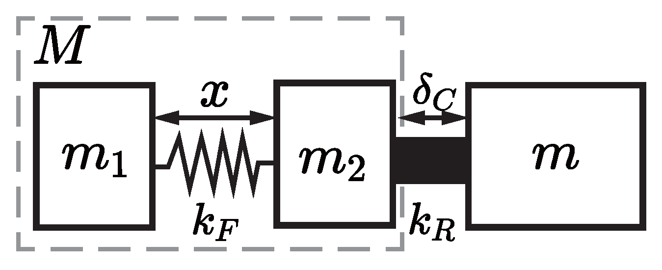
2.2. Structural Innovation: Decoupling via Flexible Interfaces

In order to overcome these limitations, we present a rigid–flexible coupled constant force component that intentionally integrates a compliant interface between the subsystems. As demonstrated in Figure 2, the initial rigid output head M is segmented into two distinct subcomponents: m 1 (the rigid base) and m 2 (the contact head). These components are linked by a flexible element characterized by a stiffness k F , where k F is significantly less than k R . The resulting contact force can be expressed as follows:
F C = k F   ·   x
where x represents the elastic deformation of the flexible interface. This structural modification fundamentally alters the force–displacement relationship while maintaining equivalent force output capability.

2.3. Key Performance Advantages

2.3.1. Reduced Force–Displacement Sensitivity

The force–displacement sensitivity coefficient is reduced by three orders of magnitude compared with rigid models:
F C x = k F ( k F / k R 10 3 10 4 )
where the range of k F / k R is empirically derived from experimental tests on the compliant hinge prototypes in [42].
This facilitates efficient force regulation via millimeter-scale positioning (ranging from 0.1 to 1 mm) as opposed to micron-level control. In the context of a target force error tolerance of Δ F C max = 0.1 N, the necessary positioning precision is adjusted to Δ x = Δ F C max / k F 0.1 mm, assuming a stiffness constant of k F = 1 × 10 3 N/m. This adjustment notably simplifies the complexity of implementation.

2.3.2. Enhanced Disturbance Rejection Capability

The compliant interface functions as a mechanical low-pass filter, effectively attenuating external disturbances. Upon exposure to environmental perturbations, such as object displacement denoted as Δ δ C , the subsequent variation in force can be expressed as follows:
Δ F C = k F   ·   k R k F + k R   ·   Δ δ C k F   ·   Δ δ C ( k F k R )
This indicates a force suppression ratio of k F / k R in relation to rigid architectures. The intrinsic mechanical compliance serves to effectively isolate high-frequency disturbances from the control system, thereby facilitating the maintenance of robust force without the necessity for ultra-fast control responses.

2.3.3. Facilitation of Control Strategy Implementation

The diminished sensitivity to positional inaccuracies enables control algorithms to emphasize dynamic responsiveness rather than achieving extreme precision in positioning. The structural transformation facilitates the conversion of the original rigid system into a control plant characterized by favorable conditioning and adjustable compliance. This feature enables the application of both linear control methods, such as PID controllers, and more sophisticated approaches, including ADRC, which will be elaborated upon in Section 3. The mechanical compliance serves as a natural buffer against transient disturbances, thereby alleviating the demands placed on control systems to address high-frequency perturbations.

3. Control System Implementation and Comparative Analysis

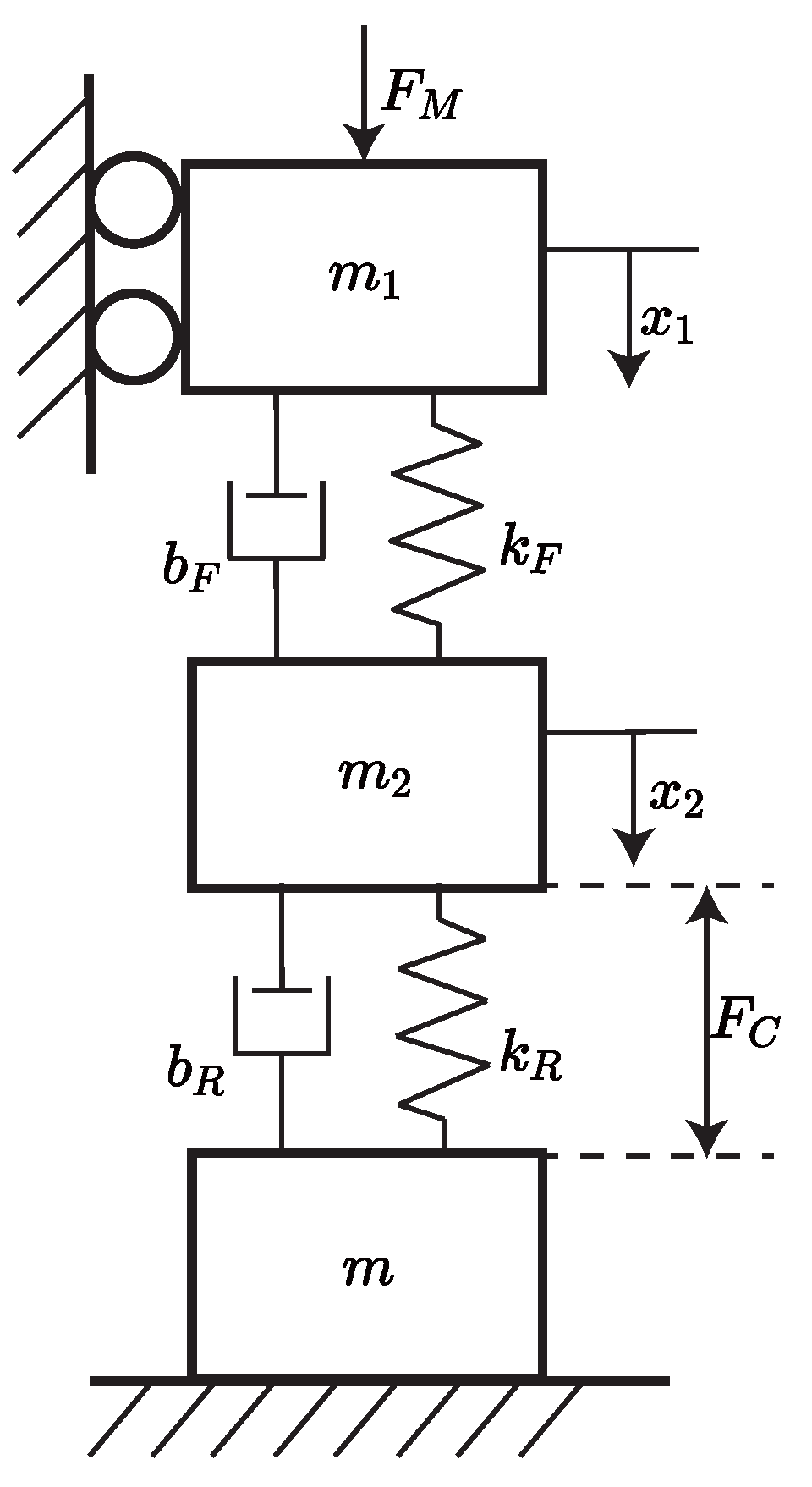
3.1. Dynamic Modeling of Rigid–Flexible Coupled Constant-Force Mechanism

Utilizing the novel rigid–flexible coupled contact model illustrated in Figure 2, we develop the dynamic model of a rigid–flexible coupled constant-force control mechanism as shown in Figure 3. The proposed mechanism for rigid–flexible coupled constant-force control, as depicted in Figure 3, consists of two interconnected masses, denoted as m 1 and m 2 . A flexible element characterized by stiffness k F and damping b F connects masses m 1 and m 2 . Simultaneously, the contact object m is rigidly attached to m 2 via interface parameters k R (stiffness) and b R (damping). It is important to highlight that the relationship between stiffness parameters is characterized by k F k R , which guarantees that the contact interface exhibits predominant rigidity while allowing for flexibility in the coupling between masses.
During operation, the servo-driven force F M actuates m 1 , resulting in displacement x 1 . This motion transmits to m 2 through the flexible coupling, resulting in displacement x 2 . The contact deformation between m 2 and m is represented by x 2 , resulting in a contact force F C defined by
F C = b R   ·   x 2 ˙ + k R   ·   x 2 .
The dynamic equilibrium of m 1 and m 2 can be expressed as
m 1   ·   x 1 ¨ b F x 2 ˙ x 1 ˙ k F x 2 x 1 = F M
m 2   ·   x 2 ¨ + b F x 2 ˙ x 1 ˙ + k F x 2 x 1 + b R   ·   x 2 ˙ + k R   ·   x 2 = 0 .
By coupling the contact force equation with the dynamics of m 2 , the transfer function relating F C ( s ) to X 1 ( s ) is derived:
F C ( s ) X 1 ( s ) = ( s b R + k R ) ( s b F + k F ) s 2 m 2 + ( b F + b R ) s + k F + k R = s 2 b F b R + s b F k R + s b R k F + k F k R s 2 m 2 + ( b F + b R ) s + k F + k R .
In practical applications, given that both damping coefficients satisfy b R , b F min ( k R , k F ) , the cross-terms containing b R b F , s b F k R , and s b R k F become dominated by the k F k R term. This justifies the simplified form:
F C ( s ) X 1 ( s ) = k R k F s 2 m 2 + ( b F + b R ) s + k F + k R .
Equation (9) can be rewritten as
F C ( s ) X 1 ( s ) = K ω n 2 s 2 + 2 s ζ ω n + ω n 2 .
where K = k F k R k F + k R , ζ = b F + b R 2 m 2   k F + k R , ω n = k F + k R m 2 .
This simplified form verifies that the system demonstrates second-order dynamics, defined by its intrinsic stiffness and inertia parameters. The simplified model establishes a fundamental framework for evaluating stability and devising force controllers in the next sections.

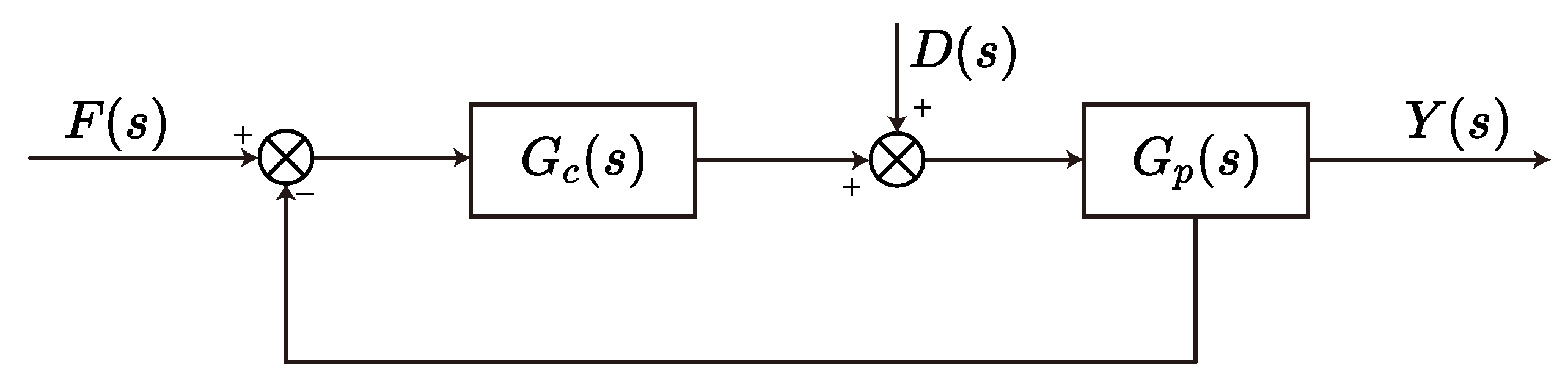
3.2. PID-Based Constant-Force Control System Design

The PID-controlled constant-force system for the rigid–flexible coupled mechanism, seen in Figure 4, incorporates a feedback loop to manage output force Y ( s ) in response to external disturbances D ( s ) . The variable F ( s ) signifies the intended force, whereas G c ( s ) and G p ( s ) indicate the PID controller and the plant dynamics described by (10), respectively. The system equation is expressed as
Y ( s ) = G c F ( s ) Y ( s ) + D ( s ) G p ,
where the PID controller G c ( s ) combines proportional, integral, and derivative actions:
G c = k p + k i s + k d s .
Substituting G c ( s ) into the closed-loop equation yields the transfer functions for Y ( s ) :
Y ( s ) = ( s 2 k d + k p s + k i ) G p ( s 2 k d + k p s + k i ) G p + s F ( s ) + s G p ( s 2 k d + k p s + k i ) G p + s D ( s ) .
This result emphasizes two critical components: (1) the numerator term ( s 2 k d + k p s + k i ) G p controls the system’s response to the reference force F ( s ) , and (2) the denominator ( s 2 k d + k p s + k i ) G p + s determines closed-loop stability and disturbance rejection. The derived model illustrates that the steady-state accuracy is improved by increasing k i , whereas high-frequency oscillations are mitigated by k d . The initial PID parameters were first obtained using the tuning methodology from [37], followed by experimental fine-tuning to balance robustness and responsiveness in practical applications.

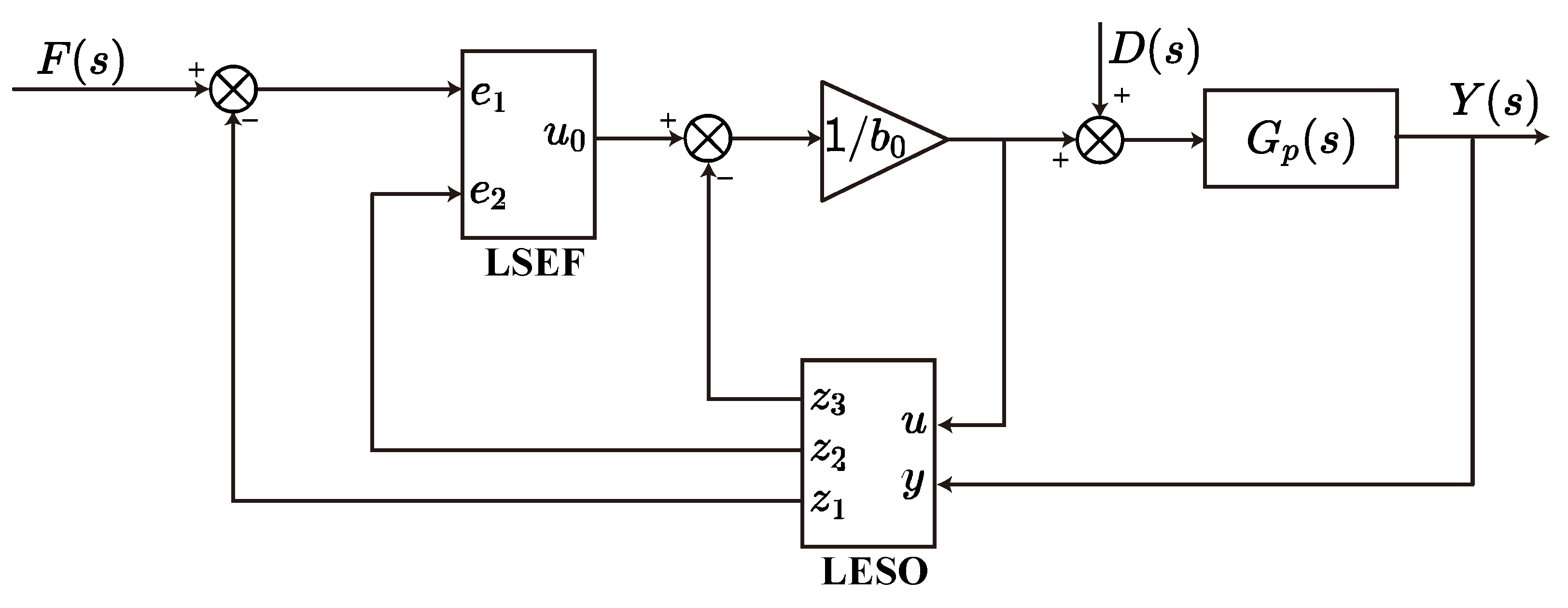
3.3. ADRC-Based Constant-Force Control System Design

The ADRC strategy applied to the rigid–flexible coupled mechanism, as illustrated in Figure 5, utilizes a Linear Extended State Observer (LESO) alongside a linear state error feedback (LSEF) integrated with proportional–derivative (PD) control to ensure effective force regulation. The input to the system, denoted as F ( s ) , represents the desired force, while Y ( s ) signifies the output force. Additionally, D ( s ) accounts for external disturbances, and G p ( s ) serves to model the dynamics of the plant described by (10). The ADRC framework incorporates disturbance estimation and compensation through the use of LESO, whereas LSEF is responsible for generating the control signal u 0 by utilizing tracking errors.
The nominal plant G p ( s ) (10) is a second-order system. Its dynamics are expressed as
y ¨ = a 1 y ˙ a 0 y + w + b u
where y = F C (output force), u = X 1 (input position), w denotes external disturbances, and a 1 , a 0 , b are partially known parameters. Let b 0 represent the known component of b. Equation (14) is rewritten to isolate the total disturbance f:
y ¨ = a 1 y ˙ a 0 y + w + ( b b 0 ) u f + b 0 u = f + b 0 u ,
where f aggregates internal uncertainties (e.g., unmodeled nonlinearities) and external disturbances.
A state vector is extended to include f as the third state:
h = h 1 h 2 h 3 = y y ˙ f
This yields the continuous state-space model
h ˙ = A h + B u + E f ˙ y = C h
with
A = 0 1 0 0 0 1 0 0 0 , B = 0 b 0 0 , C = 1 0 0 , E = 0 0 1 .
A LESO is constructed to estimate h :
z ˙ = A z + B u + L ( y y ^ ) y ^ = C z
where z = [ z 1 , z 2 , z 3 ] T estimates [ y , y ˙ , f ] T , and L = [ β 1 , β 2 , β 3 ] T is the observer gain. Gains are parameterized by the observer bandwidth ω o [37]:
β 1 = 3 ω o , β 2 = 3 ω o 2 , β 3 = ω o 3
The control input u is designed to cancel f and reduce the system to a cascade integrator form:
u = u 0 z 3 b 0
where z 3 is the estimated disturbance. The virtual control input u 0 is generated by a PD controller (i.e., LSEF):
u 0 = k p ( F ( s ) z 1 ) k d z 2
with F ( s ) being the reference force. This completes the ADRC structure, actively compensating for disturbances without explicit model dependency.
The entire Laplace-domain equations for LESO and LSEF are
s z 1 = z 2 β 1 ( z 1 Y ( s ) ) , s z 2 = z 3 β 2 ( z 1 Y ( s ) ) + b 0 u 1 , s z 3 = β 3 ( z 1 Y ( s ) ) , u 0 = k p ( F ( s ) z 1 ) k d z 2 , u 1 = u 0 z 3 b 0 , Y ( s ) = ( u 1 + D ( s ) ) G p ,
where z 1 estimates the position of m 2 in (7), z 2 estimates the velocity of m 2 , z 3 estimates the total disturbance (external disturbances + unmodeled dynamics), β 1 , β 2 , β 3 are observer gains, and k p , k d are PD controller parameters.
Solving these equations yields the closed-loop transfer functions for Y ( s )
Y ( s ) = A 2 G p 1 A 1 G p F ( s ) + G p 1 A 1 G p D ( s ) ,
with
A 1 = s 2 β 1 k p + s 2 β 2 k d + s 2 β 3 + s β 2 k p + s β 3 k d + β 3 k p b 0 s 2 + s β 1 + s k d + β 1 k d + β 2 + k p s , A 2 = k p s 3 + s 2 β 1 + s β 2 + β 3 s b 0 s 2 + s β 1 + s k d + β 1 k d + β 2 + k p .
The numerator A 2 G p regulates reference tracking, whereas the denominator 1 A 1 G p dictates disturbance rejection and stability. LESO accurately assesses and mitigates disturbances D ( s ) , as shown by the second term of Y ( s ) . Adjusting β 1 , β 2 , β 3 improves observer bandwidth, whereas k p and k d control transient performance. Practical implementation necessitates the equilibrium of observer dynamics and controller resilience to mitigate the impacts of rigid–flexible coupling.

3.4. Controller Parameter Configuration

According to (10), the controlled plant in Figure 4 and Figure 5 can be modeled as a standard second-order system with resonance and damping characteristics:
G p ( s ) = ω n 2 s 2 + 2 ξ ω n s + ω n 2
where ω n = 1 ,   ξ = 0.1 .
External disturbances are introduced as a periodic sinusoidal function:
d ( t ) = sin ( ω d t ) , ω d = 1 D ( s ) = ω d s 2 + ω d 2 = 1 s 2 + 1 .
For the PID controller (Figure 4), the parameters are configured according to the tuning methodology from Reference [37]:
k p = 2 , k i = 10 , k d = 10 .
The ADRC controller (Figure 5) adopts the bandwidth parameterization method [37], with the following procedure:
  • Controller bandwidth: Set ω c = 20 rad/s to ensure rapid transient response.
  • Observer bandwidth: Define ω o = 5 ω c = 100 rad/s for disturbance estimation.
  • Feedback gains: Calculate k p = ω c 2 = 400 and k d = 2 ω c = 40 to stabilize the closed-loop dynamics.
  • Control gain: The parameter b 0 represents the designer’s estimate of the plant’s input gain b in (15). Its accurate selection is critical for ESO performance and closed-loop stability, as b 0 directly scales the disturbance compensation in the control law. Underestimation ( b 0 b ) causes sluggish disturbance rejection; overestimation ( b 0 b ) induces instability through overcompensation. We employ the following systematic tuning procedure: First, initialize b 0 at 50–70% of the nominal gain value derived from (23). Then, monotonically increase b 0 while observing the system’s step response. For the system in (26), b 0 = 0.5 is set to ensure both fast disturbance rejection and closed-loop stability.
  • ESO parameters: Determine observer gains as β 1 = 3 ω o = 300 , β 2 = 3 ω o 2 = 30 , 000 , and β 3 = ω o 3 = 1 , 000 , 000 to ensure accurate state and disturbance estimation.

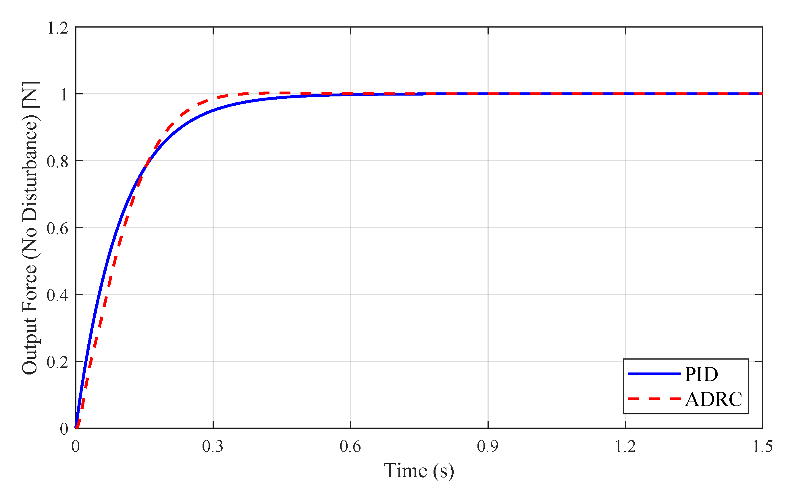
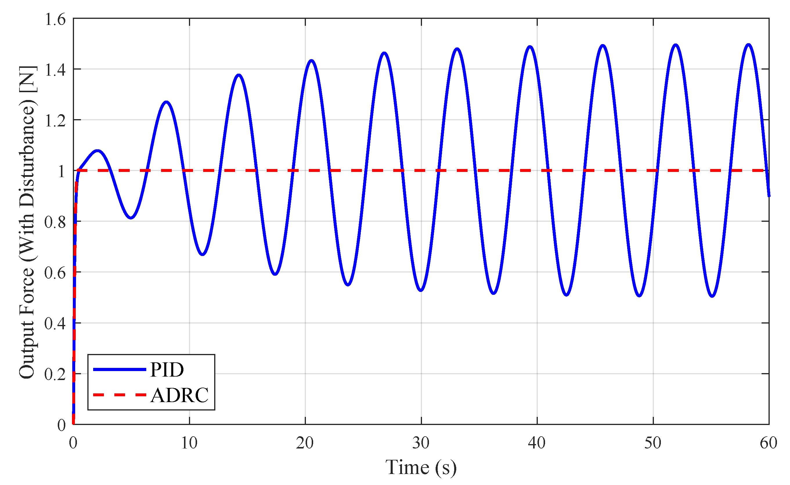
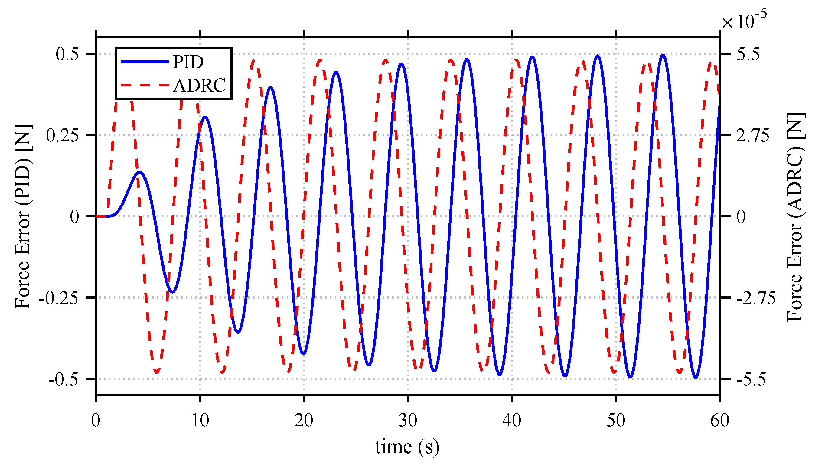
3.5. Comparative Analysis of PID and ADRC in Constant-Force Control

By integrating the above parameters into the PID-based and ADRC-based constant force control systems (Figure 4 and Figure 5), unit step responses under both disturbance-free and disturbed conditions are simulated. All simulations (Figure 6, Figure 7, Figure 8) were executed in MATLAB/Simulink R2020a. The block diagrams precisely replicate the control architectures in Figure 4 and Figure 5, with parameters detailed in Section 3.4. The resulting step responses (Figure 6 and Figure 7) and comparative error analysis (Figure 8) are discussed to evaluate robustness and transient performance.
The step responses of the PID and ADRC controllers, as depicted in Figure 6, exhibit a remarkable similarity under disturbance-free conditions, with both systems achieving stabilization within 0.5   s . The PID force attains a value of 0.993   N at t = 0.5   s , whereas the ADRC method achieves 1.002   N . This indicates a comparable degree of steady-state precision, with a variance of less than 0.001   N . The observed similarity can be ascribed to the linear feedback structure intrinsic to PID controller, in conjunction with the essential control capability of ADRC controller in the absence of external disturbances. However, as demonstrated in Figure 7, a significant difference is apparent in the presence of periodic disturbances. The PID controller exhibits pronounced oscillatory behavior, with the output force attaining a peak of 1.48   N at t = 30   s . Conversely, the ADRC controller proficiently constrains deviations to ± 0.02   N , attaining stabilization within 0.1   s post-disturbance. The observed resilience can be attributed to the LESO employed in ADRC, which proficiently estimates and alleviates the impact of disruptions via real-time state compensation.
The effectiveness of ADRC in decreasing disturbances is further demonstrated in Figure 8. The PID error displays oscillatory behavior, varying between ± 0.5   N , and shows a divergent trend over time, as indicated by a recorded value of 0.46   N at t = 30.15   s . The observed oscillations reveal a basic constraint of PID controllers in adapting to dynamic disturbances, stemming from their fixed-gain design. Conversely, the ADRC system demonstrates nearly negligible errors, limited to ± 5 × 10 5   N . The LESO is responsible for this performance, as it efficiently isolates and mitigates disturbances before they enter the control loop. The quantitative analysis demonstrates a 98.5 % reduction in mean absolute error and a 99.9 % suppression of oscillation energy when compared to PID, thereby confirming the nonlinear adaptive advantages of ADRC. While validation emphasized single-tone disturbances—reflecting dominant-frequency vibrations in machining—ADRC’s disturbance-agnostic design extends to multi-frequency scenarios. Supplemental simulation tests ( ω d = 2–3 Hz) are performed and confirmed consistent superiority over PID, with force-fluctuation amplitudes reduced across frequencies. Real-world disturbances (interpretable as sinusoidal superpositions) are thus expected to yield analogous performance advantages.
The results highlight the significant advantage of ADRC in practical scenarios, where disturbances are an inherent aspect of the environment. Although PID control demonstrates satisfactory performance in environments devoid of disturbances, its inherently linear structure is insufficient for effectively managing time-varying uncertainties. The LESO-driven framework developed by ADRC guarantees stable and accurate force control in the presence of dynamic perturbations. This characteristic renders it essential for applications that necessitate constant-force regulation, including precision force-sensitive assembly, compliant material processing, and medical devices that require consistent contact force.

4. Experiment

To verify the comparative conclusions made from the simulation studies in Section 3, an extensive experimental platform was established based on the dynamic model of the rigid–flexible coupled force control actuator depicted in Figure 3. This section offers a comprehensive overview of the mechanical architecture, hardware integration, and experimental technique.

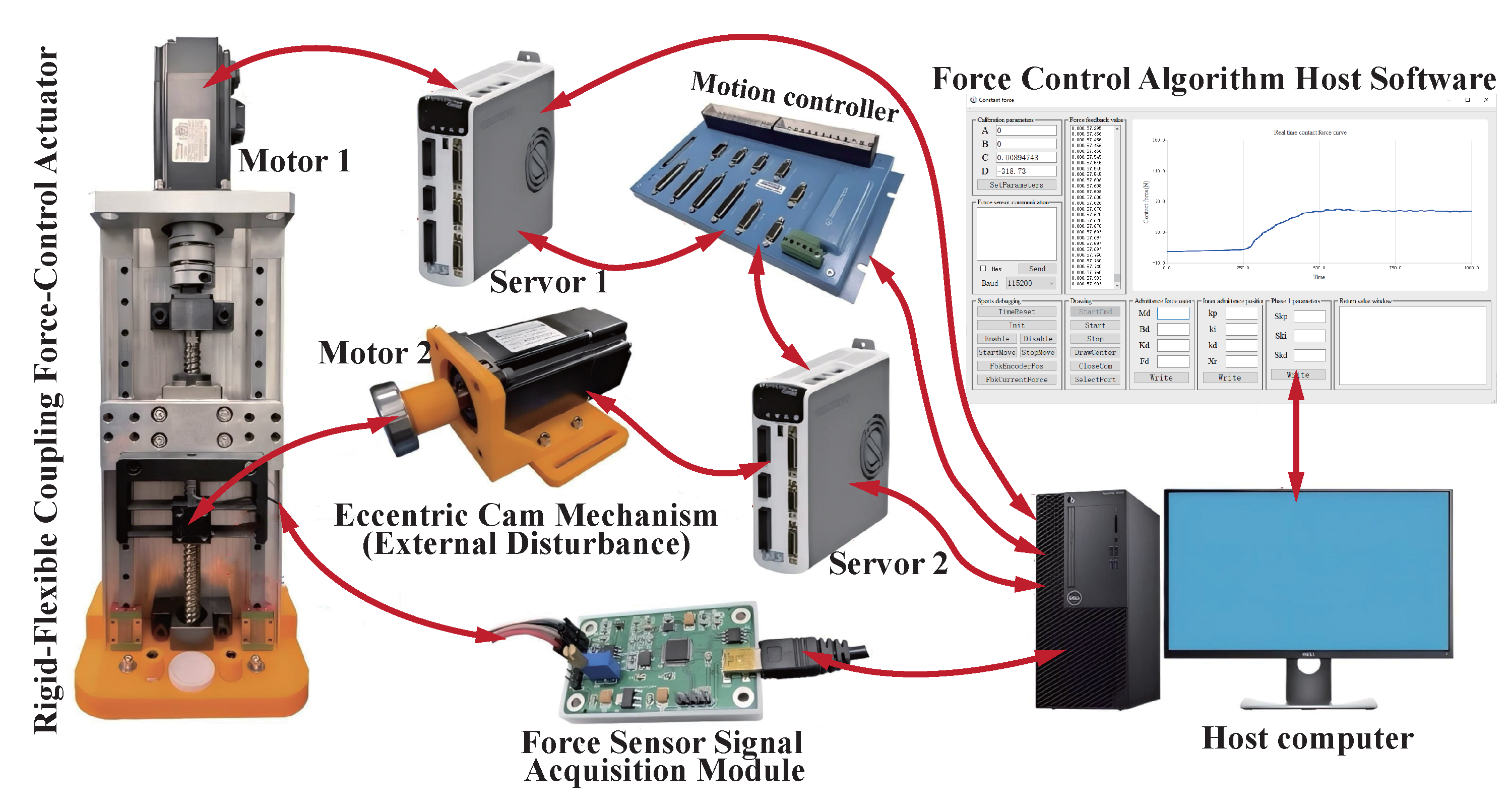
4.1. Experimental Prototype Composition

The experimental platform (Figure 9) was developed to evaluate the efficacy of the rigid–flexible coupled force control actuator (Figure 10) utilizing PID and ADRC control techniques. The prototype comprises three primary components:
  • Rigid–Flexible Coupled Force Control Actuator: The actuator consists of a rigid frame, four parallel leaf-spring flexure hinges, a flexible working stage, and an SBT630B-10Kg force sensor. The inflexible framework, linked to a servo motor-operated ball screw mechanism, facilitates extensive displacement, whereas the adaptable working stage produces the requisite output force. The flexure hinges, constructed from 7075-T6 aluminum alloy (Young’s modulus E = 7200   MPa ), utilize a corner-fillet leaf-spring configuration with dimensions l = 0.033   m , w = 0.02   m , t = 0.001   m , and r = 0.002   m (Figure 11). The stiffness of each individual hinge is determined to be k g = 55 , 592   N / m . The overall stiffness of the actuator ( k s ) is the sum of the contributions from four hinges ( 4 k g ) and the force sensor ( k f = 200 , 000   N / m ), resulting in k s = 422 , 368   N / m . This guarantees that the actuator functions within the elastic deformation range, even at the maximum safe deformation ( Δ y = 0.4   mm ) of the force sensor, which corresponds to a force capacity of F s = 168.9   N .
  • Eccentric Cam Mechanism: As illustrated in Figure 12 and Figure 13, a servo motor actuates an eccentric cam to produce periodic sinusoidal perturbations. The cam rotates at 30 r/min, generating a vertical displacement amplitude of 2 mm, which results in a cyclic perturbation force exerted on the flexible working stage. This configuration replicates the external disturbances examined in the simulation (Section 3).
  • Real-Time Control system: The experimental platform employs a custom-developed force sensor signal acquisition module communicating via USB and a motion control card (GTS-400-PG-VB, GoogolTech. Inc., China) interfaced directly through the host PC’s PCIe slot. Both components achieve direct hardware-level real-time communication with the dedicated host software, maximizing control loop determinism as depicted in Figure 9. Discrete-time formulations of both PID and ADRC controllers are directly implemented within the host software. The force acquisition module conditions the sensor’s differential signal through hardware-based amplification and filtering circuitry. An onboard ADC converts this analog signal, which is then processed by the microcontroller incorporating an FIR filter before transmission as a digital contact force value to the host PC. This design, utilizing exclusively digital signals for communication beyond the acquisition unit, significantly mitigates external noise interference on the critical force feedback.

4.2. Experimental Test Conditions

To systematically evaluate the performance of PID and ADRC controllers under varying conditions, two test scenarios were designed:
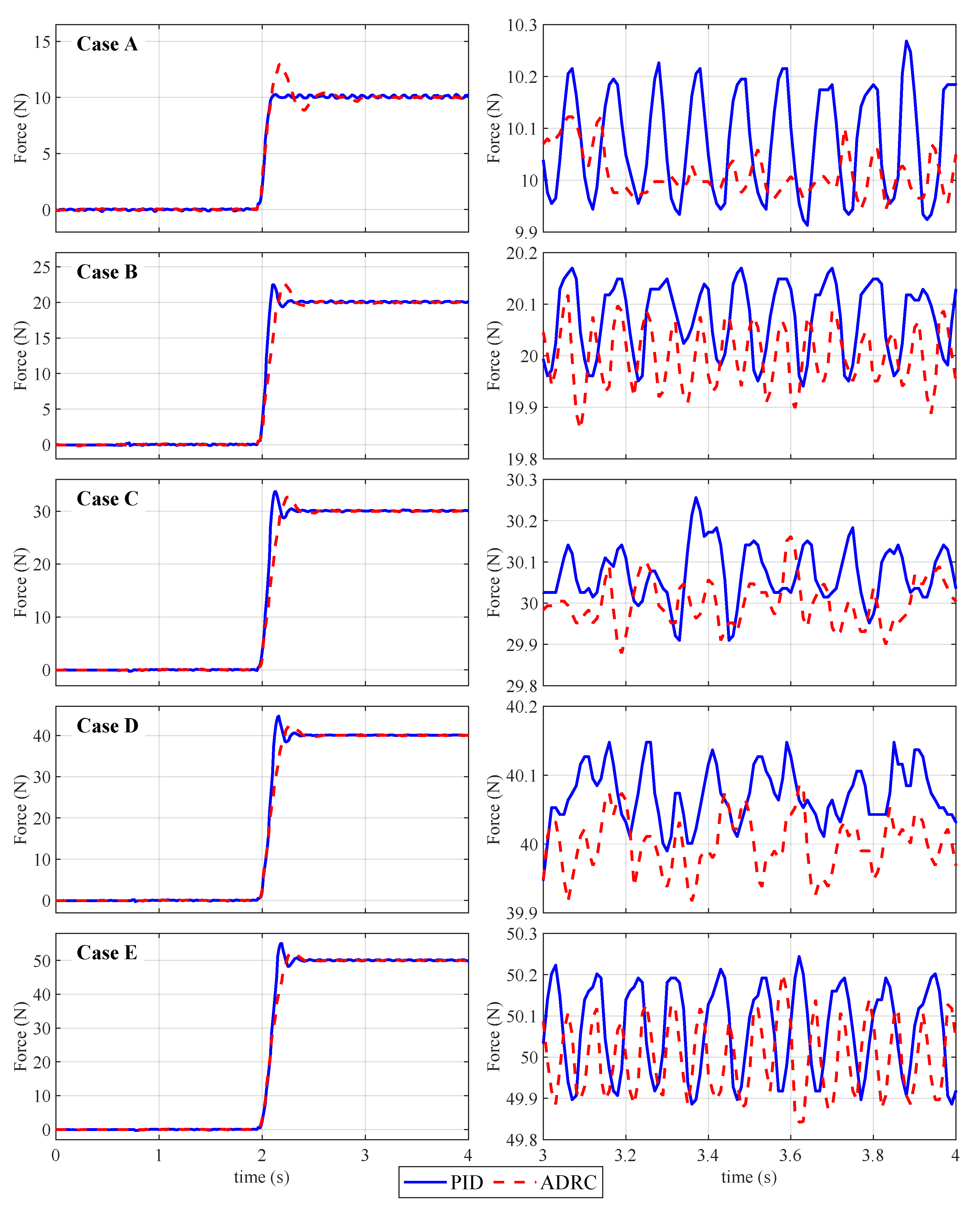
  • Disturbance-Free Case: The eccentric cam mechanism shown in Figure 12 is deactivated. Step force commands (Cases A-E: 10 N, 20 N, 30 N, 40 N, and 50 N) are sequentially applied to the actuator. Steady-state force tracking errors and response times are recorded for both PID and ADRC strategies.
  • Disturbance-Induced Case: The eccentric cam mechanism is activated to impose a sinusoidal disturbance force (Figure 13) while maintaining the same step force commands (Cases A–E). The controllers’ability to reject disturbances and maintain stable force output is quantified by analyzing force fluctuation amplitudes and recovery times. All experiments are repeated three times to ensure statistical reliability.
The test conditions align with the simulation scenarios in Section 3, enabling direct comparison between simulated and experimental results. The force sensor’s sampling rate is set to 1   kHz , and position feedback is synchronized for comprehensive data analysis. Both PID and ADRC parameters were initialized via [37], experimentally refined on Case A, and held constant for Cases B–E to objectively evaluate robustness against unknown disturbances.

4.3. Experimental Implementation

The experimental validation of the rigid–flexible coupled force control system was conducted using the integrated test platform illustrated in Figure 12. This system operates through coordinated interaction between the compliant actuator mechanism and the programmable disturbance generator. During operation, the servo motor drives the rigid base module, which transmits motion through the flexible hinges to the end-effector stage. As the end-effector maintains contact with the workpiece surface, the compliant hinges undergo controlled elastic deformation in the 0.1–1 mm range, enabling force regulation through structural compliance rather than micron-level positioning. Simultaneously, the disturbance cam mechanism, powered by a dedicated rotary motor, generates precise sinusoidal forces normal to the contact surface. These programmable disturbances (0.5–5 Hz frequency, 5–50 N amplitude) simulate real-world environmental perturbations encountered in industrial applications like robotic grinding.
Figure 9 elucidates the complete signal flow and component integration enabling closed-loop force control. The operational sequence initiates within the custom Matlab(2020A)-based host software, which runs on the industrial control computer and simultaneously coordinates the actuator’s force regulation and disturbance profile generation. Control commands are routed through the motion control card (GTS-400-PG-VB, Googoltech. Inc., China) installed in the computer’s PCIe slot, connected to the terminal board (GT2-400-ACC2-VB-G, Googoltech. Inc., China) via fiber-optic communication. The terminal board interfaces directly with two servo drives (CDHD2-006-2A-AP1, Servotronix. Ltd., China): Motor 1 governs the main actuator motor responsible for force application, while Motor 2 controls the disturbance cam motor. Real-time force feedback is provided by a force sensor mounted at the end-effector–workpiece interface, with measurements transmitted through a dedicated signal conditioning module (with FIR filter) to the computer. The control algorithm processes these force information along with encoder feedback from both axes at 500 Hz update rate, converting force errors to analog voltage signals (±10 V range) that drive the servo actuators. This closed-loop architecture enables precise force tracking while actively compensating for the programmed disturbances.

4.4. Results and Discussion

The experimental results (Figure 14 and Figure 15, Table 1) validate the simulation findings from Section 3 and elucidate intricate performance trends. In disturbance-free settings, both controllers attained similar steady-state errors (SSE < 0.25 N), consistent with the simulation’s forecast of negligible discrepancies in optimal scenarios. In disturbance-induced scenarios, ADRC demonstrated enhanced robustness: the absolute SSE of ADRC (0.2–0.5 N) was 96.3% lower than that of PID (4.5–5.4 N), with settling times decreased by 90% (0.46–0.56 s compared to >5 s). The relative SSE (absolute error normalized by target force) significantly diminished with increased force commands for both controllers (e.g., PID: 54% at 10 N compared to 10.2% at 50 N; ADRC: 2% at 10 N compared to 1% at 50 N). This trend indicates that the compliance of the rigid–flexible coupled mechanism reduces error sensitivity to positional deviations more efficiently under greater forces, as expected by the relationship Δ F C k F   ·   Δ δ C .
The slightly higher absolute SSE in cases D–E (0.5 N for ADRC compared to 0.2 N in Case A) might be ascribed to two factors: (1) nonlinear friction in the ball screw mechanism intensifies under elevated loads, partially diminishing the ESO’s compensation efficacy; (2) the sinusoidal disturbance frequency ( ω d = 1 rad / s ) nears the actuator’s resonant frequency ( ω n = 1 rad / s ), exacerbating transient oscillations. Notwithstanding these hurdles, ADRC sustained force deviations within ± 0.5 N in all instances, surpassing PID by a significant margin. These experimental results validate the principal conclusion of the simulation: ADRC’s disturbance suppression ratio ( k F / k R = 10 3 ) efficiently decouples external disturbances from the control loop, while PID’s linear feedback inadequately responds to dynamic uncertainty.
The superior performance of ADRC under dynamic disturbances fundamentally stems from its disturbance-agnostic architecture, which directly addresses PID’s inherent limitations. While PID relies on fixed gains that cannot adapt to varying disturbance spectra (causing phase lag and amplified tracking errors), ADRC’s Linear Extended State Observer (LESO) actively estimates and compensates for aggregated disturbances in real-time. This transforms the plant into a nominal double-integrator form, maintaining consistent bandwidth regardless of disturbance dynamics. Conversely, PID’s integral term accumulates errors during persistent disturbances, leading to windup saturation and overshoot. The feedforward-free design of ADRC further eliminates PID’s model-dependency vulnerability, enabling robust force regulation despite unmodeled nonlinearities. This core architectural distinction explains ADRC’s consistent superiority across all test scenarios.

5. Conclusions

This study presents an innovative rigid–flexible coupled actuator integrated with Active Disturbance Rejection Control (ADRC) for enhanced constant force control. The compliant hinge design significantly reduces contact stiffness (from 10 6 to 10 3 N / m ), enabling effective force management via millimeter-scale positioning while inherently attenuating high-frequency disturbances. The ADRC framework, utilizing its Extended State Observer (ESO), provides real-time estimation and compensation of dynamic uncertainties, eliminating the need for precise system modeling. Experimental results demonstrate superior performance over traditional PID control, particularly under disturbances, achieving force deviations within ± 0.2 N with faster stabilization. This approach reconciles structural rigidity with targeted compliance, ensuring precision motion along key axes while enhancing adaptability in disturbance-sensitive directions. However, this work primarily focuses on validating the principle; the current experimental platform is best suited for low-frequency, low-complexity contact tasks like robotic grinding, and the control system’s real-time capabilities offer room for further enhancement. Future work will address these limitations by optimizing the rigid–flexible mechanism’s structural design, refining the real-time control architecture, and rigorously evaluating performance under more complex contact scenarios and high-frequency operational demands. Extending the design to multi-axis systems and optimizing energy efficiency are also critical next steps for advancing this co-design framework towards broader intelligent manufacturing applications.

Author Contributions

Conceptualization, Z.Y.; methodology, Y.B. and Z.Y.; software, B.F.; validation, Y.B., C.J. and J.Z.; formal analysis, Y.B.; investigation, Y.B. and C.J.; resources, Z.Y.; data curation, Y.B. and J.Z.; writing—original draft preparation, Y.B.; writing—review and editing, Z.Y. and C.J.; visualization, Y.B. and J.Z.; supervision, Z.Y.; project administration, Y.B. and Z.Y.; funding acquisition, Z.Y. All authors have read and agreed to the published version of the manuscript.

Funding

This research was funded in part by the National Key R&D Program of China (2022YFB4701001), the National Natural Science Foundation of China (5247050443), Guangdong Basic and Applied Basic Research Foundation (2023B1515120014), Key Field Science and Technology Research Projects in Nanhai District (2230032004637) and the CUI CAN Program of Guangdong Province (CC/XM-202402ZJ0601).

Institutional Review Board Statement

Not applicable.

Informed Consent Statement

Not applicable.

Data Availability Statement

Data are contained within the article.

Conflicts of Interest

Author Zhijun Yang was employed by the company Foshan Huadao Ultra Precision Tech. LTD. The remaining authors declare that the research was conducted in the absence of any commercial or financial relationships that could be construed as a potential conflict of interest.

References

  1. Meng, X.; Wang, Y.; Yin, X.; Fu, H.; Sun, S.; Sun, Y. Investigation of Force-Controlled Polishing of Complex Curved PMMA Parts on a Machining Center. Machines 2024, 12, 259. [Google Scholar] [CrossRef]
  2. Tan, Q.; Basri, M.A.M.; Wang, J. Constant Force Control and Trajectory Planning of Multi-Axis Polishing Machine Using Active Disturbance Rejection Control and B-spline Curve Algorithm. IEEE Access 2024, 12, 99851–99871. [Google Scholar] [CrossRef]
  3. Dai, J.; Chen, C.Y.; Zhu, R.; Yang, G.; Wang, C.; Bai, S. Suppress Vibration on Robotic Polishing with Impedance Matching. Actuators 2021, 10, 59. [Google Scholar] [CrossRef]
  4. Zhu, Z.; Zhang, H.; Liu, G.; Zhang, D. Adaptive Variable Impedance Force/Position Hybrid Control for Large Surface Polishing. Ind. Robot. Int. J. Robot. Res. Appl. 2024, 51, 747–760. [Google Scholar] [CrossRef]
  5. Oh, S.; Kong, K. High-Precision Robust Force Control of a Series Elastic Actuator. IEEE/ASME Trans. Mechatron. 2017, 22, 71–80. [Google Scholar] [CrossRef]
  6. Chen, H.; Yang, J.; Ding, H. Robotic Compliant Grinding of Curved Parts Based on a Designed Active Force-Controlled End-Effector with Optimized Series Elastic Component. Robot. Comput.-Integr. Manuf. 2023, 86, 102646. [Google Scholar] [CrossRef]
  7. Zeng, F.; Xiao, J.; Liu, H. Force/Torque Sensorless Compliant Control Strategy for Assembly Tasks Using a 6-DOF Collaborative Robot. IEEE Access 2019, 7, 108795–108805. [Google Scholar] [CrossRef]
  8. Hameed, A.; Ordys, A.; Możaryn, J.; Sibilska-Mroziewicz, A. Control System Design and Methods for Collaborative Robots: Review. Appl. Sci. 2023, 13, 675. [Google Scholar] [CrossRef]
  9. Du, W.; Fnadi, M.; Benamar, F. Rolling Based Locomotion on Rough Terrain for a Wheeled Quadruped Using Centroidal Dynamics. Mech. Mach. Theory 2020, 153, 103984. [Google Scholar] [CrossRef]
  10. Li, C.; Zhang, F.; Guo, J.; Yang, J.; Ji, Y.; Cui, J.; Fan, W.; Gang, X. Coupling Control Theory and Bench Test of Body Attitude and Wheel Reaction Force for Multi-Axle Vehicles in 3D off-Road Terrain. Int. J. Automot. Technol. 2025, 26. [Google Scholar] [CrossRef]
  11. Xu, K.; Wang, S.; Shi, L.; Li, J.; Yue, B. Horizon-Stability Control for Wheel-Legged Robot Driving over Unknow, Rough Terrain. Mech. Mach. Theory 2025, 205, 105887. [Google Scholar] [CrossRef]
  12. Lopes, A.; Almeida, F. A Force–Impedance Controlled Industrial Robot Using an Active Robotic Auxiliary Device. Robot. Comput.-Integr. Manuf. 2008, 24, 299–309. [Google Scholar] [CrossRef]
  13. Zeng, X.; Zhu, G.; Gao, Z.; Ji, R.; Ansari, J.; Lu, C. Surface Polishing by Industrial Robots: A Review. Int. J. Adv. Manuf. Technol. 2023, 125, 3981–4012. [Google Scholar] [CrossRef]
  14. Yang, J.; Chen, H.; Qi, R.; Ding, H.; Yin, Y. A Novel Approach to Robotic Grinding Guaranteeing Profile Accuracy Using Rigid-Flexible Coupling Force Control for Free-Formed Surfaces. CIRP Ann. 2023, 72, 313–316. [Google Scholar] [CrossRef]
  15. Cao, H.; Chen, X.; He, Y.; Zhao, X. Dynamic Adaptive Hybrid Impedance Control for Dynamic Contact Force Tracking in Uncertain Environments. IEEE Access 2019, 7, 83162–83174. [Google Scholar] [CrossRef]
  16. Zhang, G.; Yang, G.; Deng, Y.; Chen, C.; Zhu, R.; Yang, K. Modeling and Force Control of a Pneumoelectric End-Effector for Robotic Continuous Contact Operations. Int. J. Adv. Manuf. Technol. 2022, 121, 1219–1234. [Google Scholar] [CrossRef]
  17. Dai, S.; Huang, C.; Yang, Y.; Ji, W.; Wang, X.; Jiang, D.; Ning, H. A Polishing Force Control Strategy for Robot Pneumatic End-Effector Based on Adaptive Sliding Mode Backstepping Algorithm. Int. J. Adv. Manuf. Technol. 2024, 133, 3383–3397. [Google Scholar] [CrossRef]
  18. Mohammad, A.E.K.; Hong, J.; Wang, D.; Guan, Y. Synergistic Integrated Design of an Electrochemical Mechanical Polishing End-Effector for Robotic Polishing Applications. Robot. Comput.-Integr. Manuf. 2019, 55, 65–75. [Google Scholar] [CrossRef]
  19. Li, J.; Guan, Y.; Chen, H.; Wang, B.; Zhang, T.; Liu, X.; Hong, J.; Wang, D.; Zhang, H. A High-Bandwidth End-Effector with Active Force Control for Robotic Polishing. IEEE Access 2020, 8, 169122–169135. [Google Scholar] [CrossRef]
  20. Ma, Z.; Hong, G.S.; Ang, M.H.; Poo, A.N. Design and Control of an End-Effector Module for Industrial Finishing Applications. In Proceedings of the 2016 IEEE International Conference on Advanced Intelligent Mechatronics (AIM), Banff, AB, Canada, 12–15 July 2016; pp. 339–344. [Google Scholar] [CrossRef]
  21. Zhu, R.; Yang, G.; Fang, Z.; Yang, M.; Chen, C.Y.; Zhang, C. Kinematic Design of a 3-DOF Force-Controlled End-Effector with Flexure Joints for Robotic Finishing Applications. In Proceedings of the 2019 IEEE/ASME International Conference on Advanced Intelligent Mechatronics (AIM), Hong Kong, China, 8–12 July 2019; pp. 1473–1478. [Google Scholar] [CrossRef]
  22. Haddadin, S.; Shahriari, E. Unified Force-Impedance Control. Int. J. Robot. Res. 2024, 43, 2112–2141. [Google Scholar] [CrossRef]
  23. Wei, Y.; Xu, Q. Design of a New Robot End-Effector Based on Compliant Constant-Force Mechanism. In Proceedings of the 2021 IEEE/RSJ International Conference on Intelligent Robots and Systems (IROS), Prague, Czech Republic, 27 September–1 October 2021; pp. 7601–7606. [Google Scholar] [CrossRef]
  24. Zhang, J.; Zhao, L.; Li, L.; Ma, F.; Chen, G. Design of Passive Constant-Force End-Effector for Robotic Polishing of Optical Reflective Mirrors. Chin. J. Mech. Eng. 2022, 35, 141. [Google Scholar] [CrossRef]
  25. Ding, Y.; Zhao, J.; Min, X. Impedance Control and Parameter Optimization of Surface Polishing Robot Based on Reinforcement Learning. Proc. Inst. Mech. Eng. Part B J. Eng. Manuf. 2023, 237, 216–228. [Google Scholar] [CrossRef]
  26. Ott, C.; Mukherjee, R.; Nakamura, Y. A Hybrid System Framework for Unified Impedance and Admittance Control. J. Intell. Robot. Syst. 2014, 78, 359–375. [Google Scholar] [CrossRef]
  27. Schumacher, M.; Wojtusch, J.; Beckerle, P.; von Stryk, O. An Introductory Review of Active Compliant Control. Robot. Auton. Syst. 2019, 119, 185–200. [Google Scholar] [CrossRef]
  28. Lew, J. Contact Control of Flexible Micro/Macro-Manipulators. In Proceedings of the International Conference on Robotics and Automation, Albuquerque, NM, USA, 25–25 April 1997; Volume 4, pp. 2850–2855. [Google Scholar] [CrossRef]
  29. Zhou, H.; Ma, S.; Wang, G.; Deng, Y.; Liu, Z. A Hybrid Control Strategy for Grinding and Polishing Robot Based on Adaptive Impedance Control. Adv. Mech. Eng. 2021, 13, 168781402110040. [Google Scholar] [CrossRef]
  30. Raibert, M.H.; Craig, J.J. Hybrid Position/Force Control of Manipulators. J. Dyn. Syst. Meas. Control 1981, 103, 126–133. [Google Scholar] [CrossRef]
  31. Bone, G.; Elbestawi, M. Active End Effector Control of a Low Precision Robot in Deburring. Robot. Comput.-Integr. Manuf. 1991, 8, 87–96. [Google Scholar] [CrossRef]
  32. Whitney, D.E. Historical Perspective and State of the Art in Robot Force Control. Int. J. Robot. Res. 1987, 6, 3–14. [Google Scholar] [CrossRef]
  33. Lu, Z.; Kawamura, S.; Goldenberg, A. Sliding Mode Impedance Control and Its Application to Grinding Tasks. In Proceedings of the IROS ’91:IEEE/RSJ International Workshop on Intelligent Robots and Systems ’91, Osaka, Japan, 3–5 November 1991; Volume 1, pp. 350–355. [Google Scholar] [CrossRef]
  34. Han, J. From PID to Active Disturbance Rejection Control. IEEE Trans. Ind. Electron. 2009, 56, 900–906. [Google Scholar] [CrossRef]
  35. Chen, Y.H.; Lan, C.C. An Adjustable Constant-Force Mechanism for Adaptive End-Effector Operations. J. Mech. Des. 2012, 134, 031005. [Google Scholar] [CrossRef]
  36. Zhang, X.; Fu, Z.; Wang, G. Design and Development of a Novel 3-DOF Parallel Robotic Polishing End-Effector. In Proceedings of the 2021 6th IEEE International Conference on Advanced Robotics and Mechatronics (ICARM), Chongqing, China, 3–5 July 2021; pp. 352–357. [Google Scholar] [CrossRef]
  37. Gao, Z. Scaling and Bandwidth-Parameterization Based Controller Tuning. In Proceedings of the 2003 American Control Conference, Denver, CO, USA, 4–6 June 2003; Volume 6, pp. 4989–4996. [Google Scholar] [CrossRef]
  38. Wu, C.; Guo, K.; Sun, J. Dual PID Adaptive Variable Impedance Constant Force Control for Grinding Robot. Appl. Sci. 2023, 13, 11635. [Google Scholar] [CrossRef]
  39. Liu, M.; Zhang, F.; He, L.; Shang, M. Dynamic Neural Network for Motion/Force Control of Manipulators with Polynomial Noises. IEEE Trans. Ind. Electron. 2024, 71, 12559–12569. [Google Scholar] [CrossRef]
  40. Chen, F.; Zhao, H.; Li, D.; Chen, L.; Tan, C.; Ding, H. Contact Force Control and Vibration Suppression in Robotic Polishing with a Smart End Effector. Robot. Comput.-Integr. Manuf. 2019, 57, 391–403. [Google Scholar] [CrossRef]
  41. Wei, Y.; Xu, Q. Design of a New Passive End-Effector Based on Constant-Force Mechanism for Robotic Polishing. Robot. Comput.-Integr. Manuf. 2022, 74, 102278. [Google Scholar] [CrossRef]
  42. Li, R.; Yang, Z.; Cai, B.; Chen, G.; Wu, B.; Wei, Y. A Compliant Guiding Mechanism Utilizing Orthogonally Oriented Flexures with Enhanced Stiffness in Degrees-of-Constraint. Mech. Mach. Theory 2022, 167, 104555. [Google Scholar] [CrossRef]
Figure 1. Force transmission in rigid contact model.
Actuators 14 00325 g001
Figure 2. Force transmission in rigid–flexible coupled contact model.
Actuators 14 00325 g002
Figure 3. Dynamic model of rigid–flexible coupled force control actuator.
Actuators 14 00325 g003
Figure 4. PID-based control diagram of rigid–flexible coupled force control actuator.
Actuators 14 00325 g004
Figure 5. ADRC-based diagram of rigid–flexible coupled force control actuator.
Actuators 14 00325 g005
Figure 6. Comparative step responses of PID- and ADRC-based constant-force control systems under disturbance-free conditions.
Actuators 14 00325 g006
Figure 7. Comparative step responses of PID- and ADRC-based constant-force control systems under external disturbances.
Actuators 14 00325 g007
Figure 8. Force error comparison of PID- and ADRC-based constant-force control systems.
Actuators 14 00325 g008
Figure 9. Experimental setup of the rigid–flexible coupled constant force control system.
Actuators 14 00325 g009
Figure 10. Structural schematic of the core rigid–flexible coupled force control actuator ( m 1 and m 2 in accordance with Figure 3).
Actuators 14 00325 g010
Figure 11. Structure diagram of corner-fillet leaf-spring flexure hinge.
Actuators 14 00325 g011
Figure 12. Experimental prototype of the rigid–flexible coupled constant force control mechanism: (a) comprehensive view of the prototype; (b) zoomed-in view of the rigid–flexible coupled force-control actuator.
Actuators 14 00325 g012
Figure 13. External disturbance.
Actuators 14 00325 g013
Figure 14. Experimental results (disturbance-free cases).
Actuators 14 00325 g014
Figure 15. Experimental results (disturbance-induced cases).
Actuators 14 00325 g015
Table 1. Experimental performance comparison.
CasesControllerDisturbance-FreeDisturbance-Induced
Absolute
SSE (N)
Relative
SSE
Settling
Time (s)
Absolute
SSE (N)
Relative
SSE
Settling
Time (s)
A (10 N)PID0.252.50%0.245.4054.00%>5
ADRC0.121.20%0.550.202.00%0.56
B (20 N)PID0.180.90%0.404.8024.00%>5
ADRC0.120.60%0.400.301.50%0.46
C (30 N)PID0.260.87%0.324.5015.00%>5
ADRC0.130.43%0.390.301.00%0.51
D (40 N)PID0.220.55%0.404.7211.80%>5
ADRC0.190.48%0.420.501.25%0.46
E (50 N)PID0.250.50%0.435.1010.20%>5
ADRC0.180.36%0.400.501.00%0.56
Disclaimer/Publisher’s Note: The statements, opinions and data contained in all publications are solely those of the individual author(s) and contributor(s) and not of MDPI and/or the editor(s). MDPI and/or the editor(s) disclaim responsibility for any injury to people or property resulting from any ideas, methods, instructions or products referred to in the content.

