1. Introduction
To complete the space gravitational wave detection, a microthruster with microNm-scale thrust noise and thrust resolution is required to realize the high-precision drag-free control mission of the satellite platform [
1]. The microthrust measurement device can accurately measure the thrust generated by the thruster and evaluate the performance of the thruster through the measurement results, which can provide the improvement direction for the thruster research [
2,
3,
4], and shorten the cycle and time of the thruster research and development.
The effect of environmental vibration on thrust measurements is an important disturbing factor. Human activities, vehicles passing by, airflow disturbance, and other factors will all disturb the thrust measurement, resulting in signal distortion or abnormality. Therefore, when selecting the measurement environment, due consideration should be given to selecting a good measurement environment. For example, when the measurement is carried out at night, vibration-damping measures are considered, such as vacuum tanks, vibration-isolated foundations, and vibration-isolated platforms [
5]. In addition, the effect of vibration on the measurement should be studied, such as using model compensation or data processing (e.g., spectrum analysis using the Fourier transform, adaptive filtering, etc.) for noise reduction [
6].
Currently, the structures of thrust measurement devices in the world mainly include the torsional pendulum structure, simple pendulum structure, and cantilever beam-based deformation structure [
7,
8]. The advantages of cantilever beam microthrust measurements are a simple structure, fast response speed, and suitability for measuring dynamic thrust. It can accurately measure the magnitude, duration, and transient response of the thrust force, but the disadvantage is that it is susceptible to vibration noise. In microthrust measurements, there are various vibration disturbances and vibration disturbances with impulses in the environment. The cantilever beam force measurement structure has very little damping, and once disturbed, it will continue to vibrate and stop, affecting the measurement. In order to minimize the effect of external environmental disturbances on thrust measurement, especially the disturbances of signals such as impulses and oscillations caused by step thrust, it is necessary to identify the step response and impulse response, and then adopt different feedback control strategies. Kakami et al. [
9] proposed a perturbation observer for evaluating high-frequency thrust variations outside the resonance frequency.
Zhang et al. [
10] utilized a feedback-controlled torsionally oscillating elastic thrust holder to achieve accurate measurements of thrust in the range of 0–200 μN. Wang Jiabin et al. [
11] designed a closed-loop control-based monofilament torsion pendulum microthrust measurement system, but the stabilization time of the system’s feedback control reaches more than 60 s, and the response period is long. Therefore, for the impulse and step interference in the microthrust measurement process, a PID control method is used, and the two signals require different PID control strategies.
Microthrust measurement devices are highly susceptible to disturbances in the external environment, such as ambient vibration, ambient temperature changes, etc., and this problem is especially prominent in thrust tests in the millinewtons scale and below. Interference from ambient noise is an unavoidable problem in practical system response measurements. If it is not effectively suppressed, it will increase the calibration error of the system parameters, resulting in the inability to obtain accurate vibration differential equations of the thrust measurement system, thus indirectly increasing the thrust measurement error. Therefore, in order to achieve the desired detection goal, it is necessary to effectively suppress the interference of environmental noise.
Through the above domestic and international research on the current status of environmental interference suppression methods for microthrust measurement devices. It can be seen that the impulse of environmental interference on the accuracy and stability of microthrust measurement cannot be ignored, and when a microthrust measurement is performed, the environment has a variety of vibrational disturbances and vibrational disturbances with impulses. Structure damping is small, and once disturbed, it will continue to oscillate and stop, affecting the measurement. In order to reduce the influence of external environmental interference on the thrust measurement, especially the interference of impulse and other signals, this study uses feedback control, combined with the learning ability of the neural network, to complete the identification and attenuation of impulse and other interference signals and step oscillations.
As a key component in mechanical, aeronautical, and aerospace engineering, the dynamic characteristics of cantilever beam structures directly affect the stability and safety of the structure. Under the effect of microthrust variation and external excitation (e.g., impulse load), the cantilever beam is prone to producing continuous vibration, which affects the microthrust measurement process. Therefore, how to effectively suppress such transient impulse-induced vibration has become a research hotspot in the field of engineering control. Although traditional passive control methods can alleviate some of the vibration problems, there are limitations such as response lag and lack of accuracy when dealing with high-frequency and sudden impulses. In recent years, active control technology has provided new ideas for cantilever beam vibration control by virtue of its advantages of fast response, high accuracy, and adjustability.
As the core structure of microthrust measurement, the vibration control of the cantilever beam is crucial for system stability and measurement accuracy. Due to the low stiffness and weak damping characteristics of the cantilever beam, the traditional linear control methods (e.g., PID) rely on accurate mathematical models, which have difficulty in coping with nonlinear time-varying conditions and multimodal coupled vibration caused by random perturbations [
12]. Fuzzy control effectively solves the problem of model uncertainty through the nonlinear mapping mechanism of linguistic rule base and subordinate function, and becomes the key technology of cantilever beam vibration suppression, whose core advantages are model-independence and strong robustness [
13].
In recent years, research has focused on the fusion of fuzzy control and intelligent algorithms for optimization. For example, Xinke Gou’s team [
14] proposed a fuzzy rule table generation method based on optimal control theory, which significantly improves the vibration suppression efficiency by combining offline computation and online execution; Pan J et al. [
15] proposed a control strategy for suppressing the buckling of cantilever structures based on fuzzy sliding mode control; Sun L’s [
16] control strategy based on fuzzy sliding mode control was applied to the control of a multi-dimensional nonlinear composite cantilever beam with large-amplitude limit ring; Jingjun Z et al. [
17] used fuzzy logic to control the vibration of smart structures with better control performance; and Singh et al. [
18] used a fuzzy logic controller to study the vibration control of an intelligent cantilever beam, and the results showed that the method could effectively suppress the vibration of the cantilever beam. In addition, Chen et al. [
19] proposed a fuzzy sliding mode active control strategy, which effectively reduces the vibration shaking phenomenon of sliding mode control by adjusting the switching gain through fuzzy rules. These studies show that fuzzy control can effectively improve the performance and robustness of cantilever beam vibration control, which provides new ideas and methods for solving the cantilever beam vibration problem.
With the increasing complexity of modern control systems, traditional control methods often struggle to meet the demands of high precision and adaptability. Particle swarm optimization (PSO) and fuzzy control have emerged as powerful tools to address these challenges. PSO, inspired by social behavior, is an efficient optimization algorithm that can quickly find optimal solutions in complex search spaces [
20]. Fuzzy control, on the other hand, excels in handling uncertainties and nonlinearities through its ability to mimic human decision-making processes [
21]. The integration of PSO and fuzzy control has shown great promise in enhancing system performance by leveraging the strengths of both methods. For instance, in energy management systems, the combination has been used to dynamically adapt PSO parameters, improving solution quality and robustness. This paper aims to explore the application of PSO-based fuzzy control in various fields, focusing on its ability to optimize control parameters and enhance system stability and adaptability. Additionally, in industrial applications, PSO-based fuzzy control has been employed to optimize the speed tracking of robotic manipulators, enhancing system stability and response time [
22].
Based on this background, this study designs a general validation experimental system with a cantilever beam step impulse vibration as the object, aiming at verifying the effectiveness of the active control strategy in transient vibration suppression. The system adopts an electromagnetic coil as an actuator to offset the vibration energy triggered by the impulse excitation by applying a reverse control force; at the same time, it combines a laser displacement sensor to monitor the vibration displacement signal in real time, and utilizes an STM32 microcontroller to realize the data acquisition and fast processing. At the level of the control algorithm, particle swarm optimization fuzzy PID (proportional-integral-derivative) regulation mechanism is introduced to optimize the response characteristics of the system by dynamically adjusting the control parameters, taking into account the control accuracy and stability. This study focuses on the transient response characteristics of the cantilever beam thrust measurement system under the step thrust and impulse disturbance. And comprehensively evaluates the robustness of the control system by comparing the impulse amplitude decay rate, stabilization time, and other key indicators before and after control. The results of the study can provide theoretical support and experimental basis for the design of a cantilever beam structure and active vibration control technology under a high dynamic loading environment. It has important engineering significance for improving the disturbance attenuation technology of cantilever beam microthrust measurement in aerospace equipment and precision instruments.
The remainder of this paper is organized as follows. In
Section 2, system modeling is introduced. In
Section 3, expectation estimation and control algorithms are introduced. In
Section 4, control algorithm experiments are conducted.
Section 5 gives the conclusions of the paper.
3. Expectation Estimation and Control Algorithms
3.1. Adaptive Kalman Displacement Expectation Estimation
Real-time simulation control of the cantilever beam based on identification results. First, an adaptive Kalman filter-based desired displacement estimation algorithm is proposed based on the displacement of the cantilever beam and the identification results, aiming to approximate the ideal step curve and provide a reliable desired displacement for control. Second, a fuzzy PID algorithm based on improved particle swarm optimization is designed. The fuzzy PID controller dynamically adjusts the Kp, Ki, and Kd parameters by real-time monitoring of system error and its rate of change, thereby suppressing thrust response oscillations and impulse oscillations of the cantilever beam.
When a cantilever beam microthrust measurement system is used for thrust calibration, the actual thrust value is unknown, and the only data that can be obtained are the vibration displacement signal of the cantilever beam. This signal is the result of a combination of factors such as step thrust, impulse disturbances, and noise. However, the PID control strategy requires a desired value as a reference. To provide an accurate reference for the control process, the expectation value needs to be estimated to approximate the ideal step change.
Ideally, the cantilever beam should stabilize at a certain position after being subjected to a thrust. By subsequent processing of the cantilever beam displacement, the magnitude of the thrust force can be calculated, thus completing the calibration task. Obviously, the cantilever beam can be stabilized quickly when the thrust force changes, and the impulse interference can be effectively suppressed in order to provide a purer signal for the subsequent processing. Therefore, detecting and distinguishing between step changes and impulse signals is crucial for improving the measurement accuracy of the system.
Regarding the identification of impulses and steps, our other article, “SE-ResNet-Based Disturbance Identification Algorithm for Microthrust Measurement System”, uses the SE-ResNet neural network for identification. The prediction accuracy is at 93%, and the total delay is about 70 ms, which basically meets the requirements.
In the microthrust measurement system, different filtering strategies are used to optimize the system performance for three states: steady state, impulse, and step change. Under steady-state conditions, the filter should effectively suppress the noise to ensure the smooth operation of the system. When an impulse disturbance occurs, the filter should be able to maintain the stability of the desired value and provide a reliable reference signal for PID control. In the case of a step change, the filter should have the ability to respond quickly and accurately estimate the value after the step, so that the PID controller can quickly suppress the oscillations caused by the step and restore the stability of the system. Ideally, after the step control, the PID output should tend to zero, and the cantilever beam remains stable.
The Kalman filter performs recursive estimation based on system dynamics models and noise statistical characteristics, but its performance is highly dependent on accurate mathematical models and steady-state noise assumptions. In practical engineering applications, if the system model is biased or the noise statistical characteristics change over time, the estimation accuracy of the filter will significantly decrease. To address this issue, adaptive Kalman filtering introduces an online parameter adjustment mechanism, such as real-time adjustment of the process noise covariance matrix or adaptive weighting of multi-sensor observation data, thereby enhancing the algorithm’s adaptability in environments with model uncertainty and time-varying noise. From an algorithmic structure perspective, adaptive Kalman filtering incorporates parameter adaptation, forming a more robust closed-loop estimation framework [
29].
Parameter adaptation session:
where
is the process noise estimation mean;
is the observation noise estimation mean;
is the process noise estimation covariance matrix,
is the observation noise estimation covariance; and
is the adaptive computation step.
Fast tracking is achieved by dynamically increasing Q and decreasing k. Impulse suppression is performed by decreasing the observation weights by increasing R and increasing k. The adaptive calculation step size is adjusted according to the recognition results of the neural network: in steady state, k adapts near the more moderate equivalent value to balance the interference of tiny jitter; in step, k adapts near the smaller value to realize the fast following effect with a small step size; and when the impulse comes, k adapts near the larger equivalent value to balance the interference of impulse jitter. According to the simulation and experimental test, the k range of steady state, step, and impulse fluctuates better near 80, 20, and 160, respectively.
As shown in
Figure 5, different filtering schemes are used for the three cases of steady state, step, and impulse, respectively. When the step change is detected, the filtering scheme should be adjusted to the fast response mode in order to truly reflect the change characteristics of the step. When the system enters the steady state, the filtering scheme is switched back to the steady-state filtering scheme to ensure the smooth transition of the state transition. Parameter transitions take a linear change to ensure a smooth transition of state transitions. Similarly, when impulse interference is detected, a specialized impulse filtering scheme should be used to suppress the interference caused by the impulse. Ideally, the estimated signal should be unaffected by impulses, reflecting only the step change and steady-state characteristics.
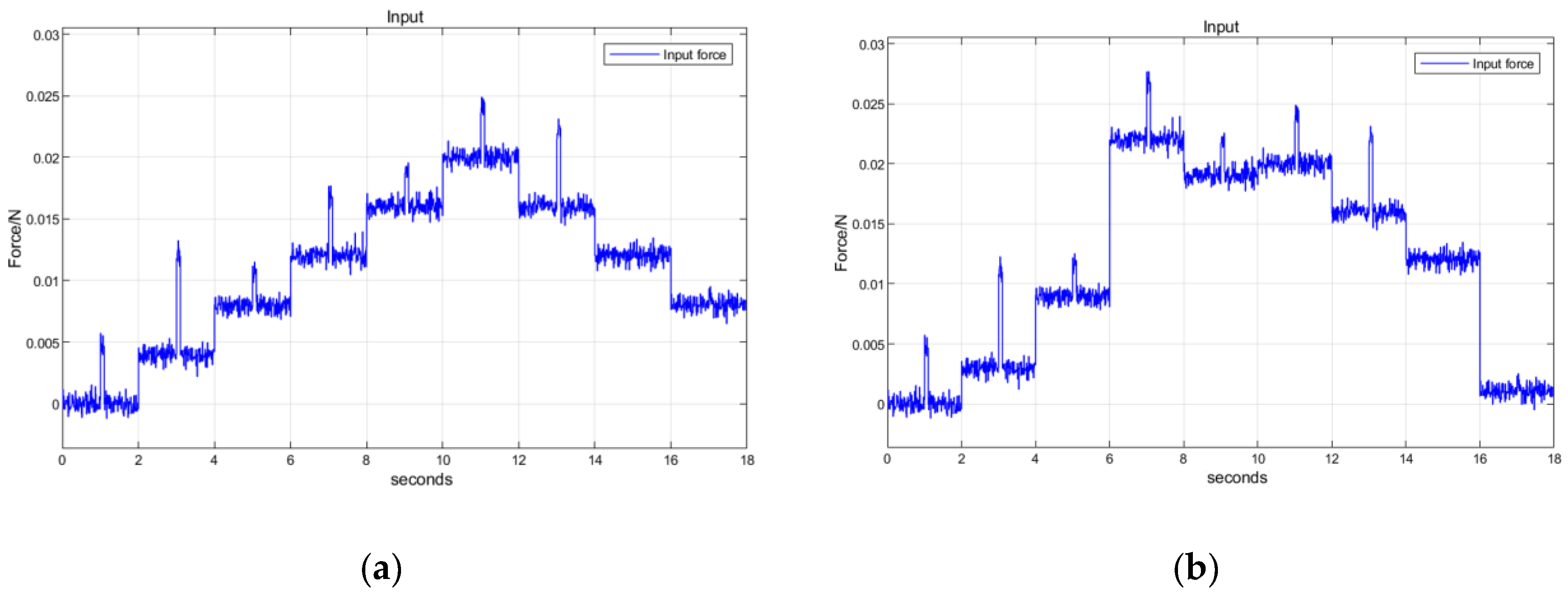
For microthrust measurement oscillation control in the mN range, the thrust change is usually in the order of several mN, the impulse size is in the order of 0–10 mN, and the noise signal is in the order of 1 mN. Therefore, Simulink simulation uses a step force input that changes once in 2 s as the signal under test, classified into two categories. As shown in
Figure 6, ordered steps each have a step difference of 4 mN, and a simulated impulse disturbance of 3 mN with a duration of 0.1 s is applied to the middle of the steps, and arbitrary step signals are used to randomize the step force and the impulse size in order to fully test the performance of the proposed algorithm.
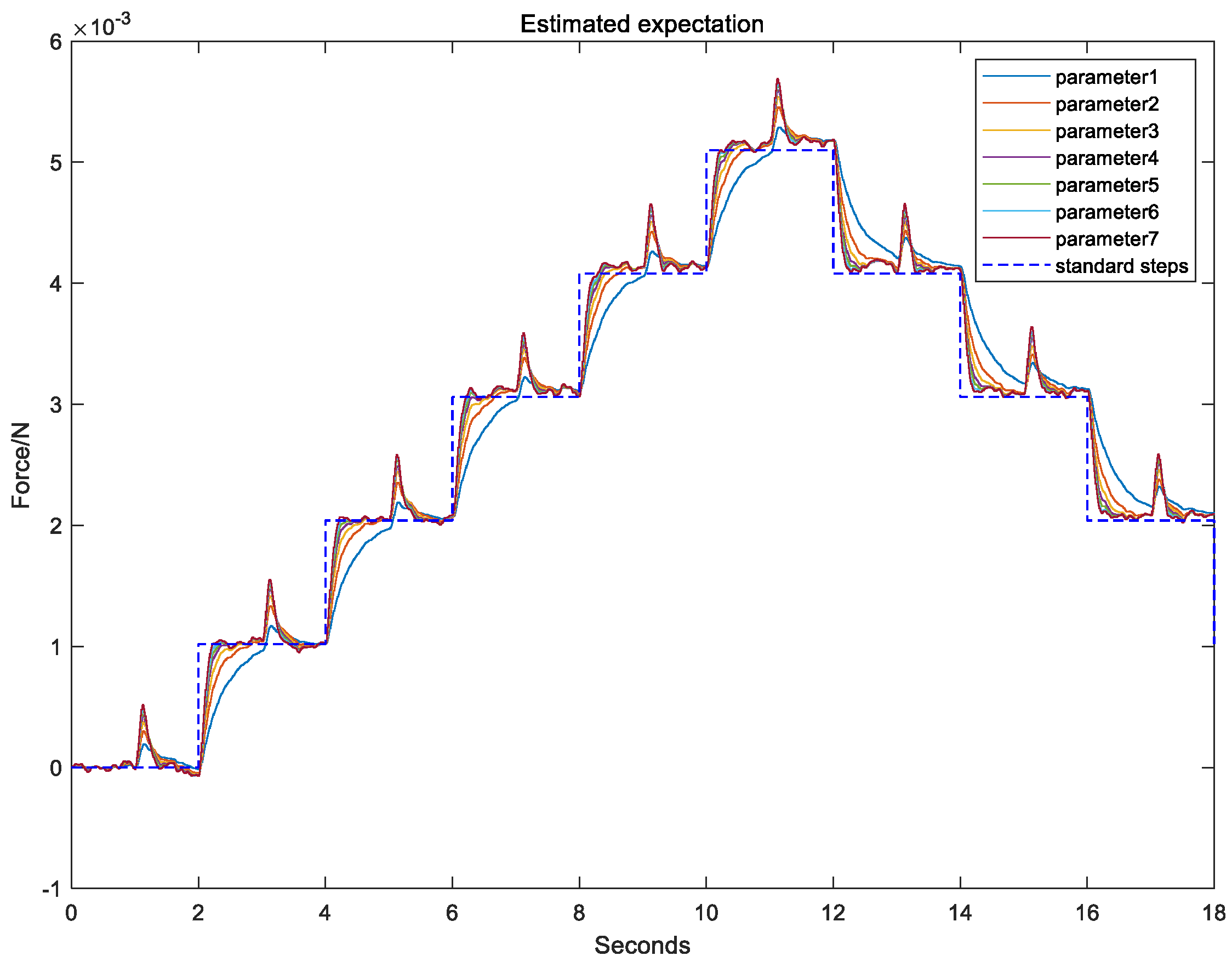
Before the estimation comparison, it should be pointed out that the expectation estimation and PID control are complementary to each other, and the control PID algorithm for this comparison is the fuzzy PID control, which has better results in the next Section.
Figure 7 shows the expectation estimation using fixed-parameter filtering, respectively, parameter 1 to parameter 7, and it can be seen that the tracking speed of parameter 1 is slower, but the suppression of impulses is a little better, and parameter 7 is faster tracking speed, but the suppression of impulses is poorer. Therefore, if the system wants to achieve both fast tracking and strong impulse suppression, it needs to identify the two signals and adopt different strategies.
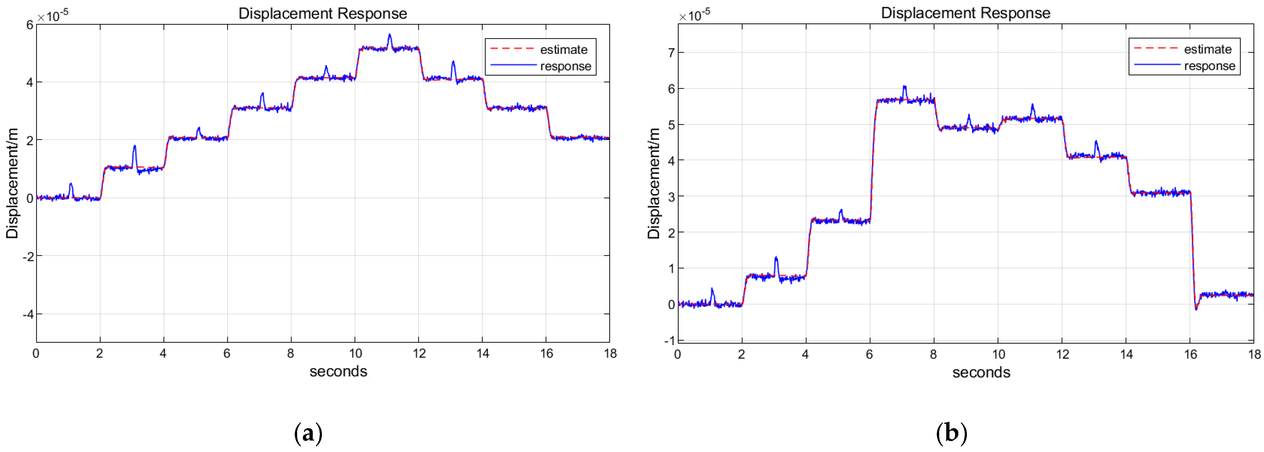
As shown in
Figure 8a, for the expectation estimation algorithm proposed in this paper, it can be seen that the expectation estimation algorithm can both track the step change signals faster, with a steady-state error of less than 5%, suppress the impulse of the impulse signals better, and keep the estimated value unchanged all the time during the impulse process, so that the expectation estimation can be as close as possible to the standard step input. As shown in
Figure 8b, for any step and impulse under the estimated signal, it can be seen that, even if the step change is very different, the size of the impulse is not the same, the expectation of the estimation algorithm can be faster tracking of the step change signal, but also better suppression of the impulse signal to meet the design requirements for the design of the subsequent control algorithms to provide a more accurate reference.
3.2. PSO Optimization Algorithm
The basic principle of the PSO algorithm is to find a suitable solution by exchanging information between each particle within the population [
30]. In each iteration, the particle updates itself by finding two optimal values,
and
, and after finding these two optimal values, the particle can then change its position and velocity using Equation (19) [
31].
where
is the number of iterations of the particle;
is the individual learning factor,
is the group learning factor, and it is often taken as
and
are two random numbers, whose values are between 0 and 1;
is the inertia weight, and the larger the
is, the stronger the global searching ability is, and the smaller the
w is, the stronger the local searching ability is;
are the velocity vector and position vector of particle
i in the
dth dimension in the wth iteration, respectively;
is the optimal solution obtained by the search of particle
i after the
kth iteration; and
is the optimal solution obtained by the search of the whole particle swarm after the
kth iteration.
Fitness function:
where
is the input step force, and
is the displacement response after the equivalent value; the square of their difference reacts to the control algorithm’s effect on the control of the step force response, the smaller the value of the fitness represents the closer the response curve is to the step, and accordingly, the smaller the overshoots and oscillations are, and the closer it is to our control goal.
3.3. Principle of Fuzzy PID Algorithm Based on PSO Optimization
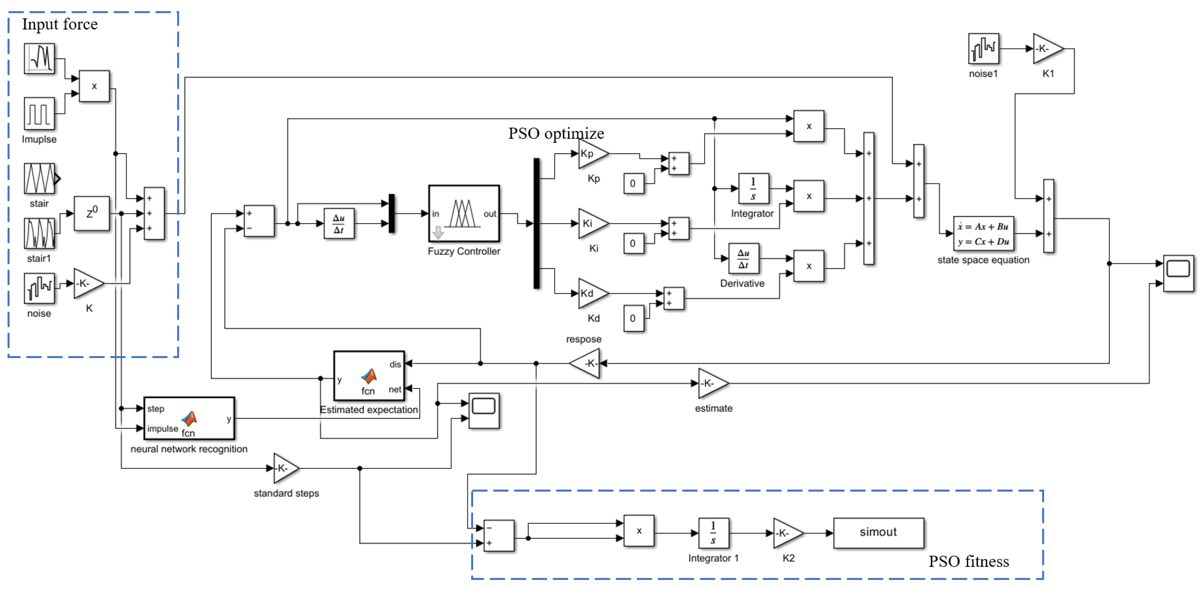
The system architecture is shown in
Figure 9. The step force and PID control force act on the cantilever beam together. The cantilever beam displacement signal is input into SE-ResNet for classification, and the desired estimation algorithm generates the displacement estimate. The system drives the PID control based on the deviation between the displacement value and the estimate, and the output control force and input force act on the cantilever beam together. The particle swarm optimization algorithm uses the step force and displacement deviation as the fitness criteria to dynamically optimize the fuzzy PID parameter domain to enhance control accuracy.
The key to the fuzzy PID controller is its ability to dynamically adjust the control parameters (proportional gain Kp, integral gain Ki, and differential gain Kd) according to the real-time control error and error changes [
32], thus realizing adaptive control of complex systems. Such controllers are particularly suitable for systems for which it is difficult to establish an accurate mathematical model or for which there are nonlinear, time-varying, and uncertainty factors [
33].
In this Section, the particle swarm algorithm is combined with fuzzy control to design a fuzzy adaptive PID controller that calculates the adjustment values of the three parameters of the PID according to the positional deviation of the cantilever beam and the rate of change in deviation, so as to realize the fuzzy PID control of the measurement system.
Fuzzy PID Controller Design
The core value of the fuzzy PID controller lies in its intelligent regulation architecture with two inputs and three outputs: by analyzing the deviation e and its rate of change ec in real time, it dynamically adjusts the three parameters ΔKp, ΔKi, and ΔKd. This mechanism implements a segmented optimization strategy: when the system has a large error, the proportional term Kp is prioritized to accelerate a dynamic response (while avoiding overshoot); as the system approaches steady state, the integral term Ki is strengthened to eliminate residual error, and the derivative term Kd is used to provide proactive compensation for the vibration trend of the cantilever beam, thereby effectively suppressing mechanical oscillations. This multi-modal adaptive characteristic demonstrates significant advantages in nonlinear system control, achieving real-time optimization of cantilever beam dynamic stability. The design process of a fuzzy PID controller primarily includes the following key steps:
- (1)
Construct the basic thesis domain
In the practical application of microthrust measurement, through the accumulation of a large amount of experimental data, the fluctuation range of the error signal e is ultimately determined to be within the interval [−0.05, 0.05]. The numerical range of the error change rate ec is even smaller, primarily concentrated within the range [−0.01, 0.01]. Subsequently, the adjustment ranges of the three PID parameters are all restricted to the range [−3, 3]. Here, the particle swarm optimization algorithm is primarily employed to dynamically optimize the output parameter range.
- (2)
Performing fuzzification
Convert precise numerical values into fuzzy language descriptions. Quantify the precise error value of 0.02 as the “PS (positive small)” language variable, and apply a seven-level fuzzy classification: NB (negative large), NM (negative medium), NS (negative small), O (zero), PS (positive small), PM (positive medium), and PB (positive large). These linguistic variables correspond one-to-one with the quantization levels [−3, −2, −1, 0, 1, 2, 3], achieving an accurate mapping between natural language descriptions such as “error is too large” and control parameters, thereby establishing an intuitive fuzzy reasoning framework.
- (3)
Selection of the membership function
Considering the computational efficiency of the STM32, a simple triangular membership function was selected, which reduces the amount of computation significantly compared to the Gaussian membership function.
- (4)
Formulation of fuzzy control rule table
The fuzzy controller is able to determine the corresponding fuzzy PID tuning values according to the fuzzy control rule table by querying the fuzzy theoretical domains of the error e and its rate of change ec. These rules are combined by several logical relationship terms to form a complete set of fuzzy logic control strategies.
Based on this kind of fuzzy logic, a total of 49 fuzzy control rules are formulated in this paper, forming a complete fuzzy control rule table, which is displayed in
Table 2,
Table 3 and
Table 4.
- (5)
Perform defuzzification
Since the fuzzy control quantities output by the system after reasoning through the fuzzy rule table are abstract values, and the actuator needs to receive precise control signals, the conversion from fuzzy quantities to precise values must be realized. For this reason, the Centroid Method is used for defuzzification in this study.
The Centroid Method, as a mathematical method of defuzzification in fuzzy logic control systems, aims to convert fuzzy sets into exact value outputs. The method is based on the concept of the geometric center of a fuzzy set and determines the final output value by calculating the weighted average position of all elements within the fuzzy set. The following is a detailed explanation of the principles and formulas of the center of gravity method [
34]:
Let the fuzzy set A be on the universe set X with the affiliation function
, then the fuzzy set A can be represented as:
The process of defuzzification is to find a point c that represents the center of the fuzzy set A. The center of gravity method calculates c as:
where the numerator is the integral of the product of all elements x in the fuzzy set A whose affiliation
represents the weighted affiliation; the denominator is the integral of the affiliation function
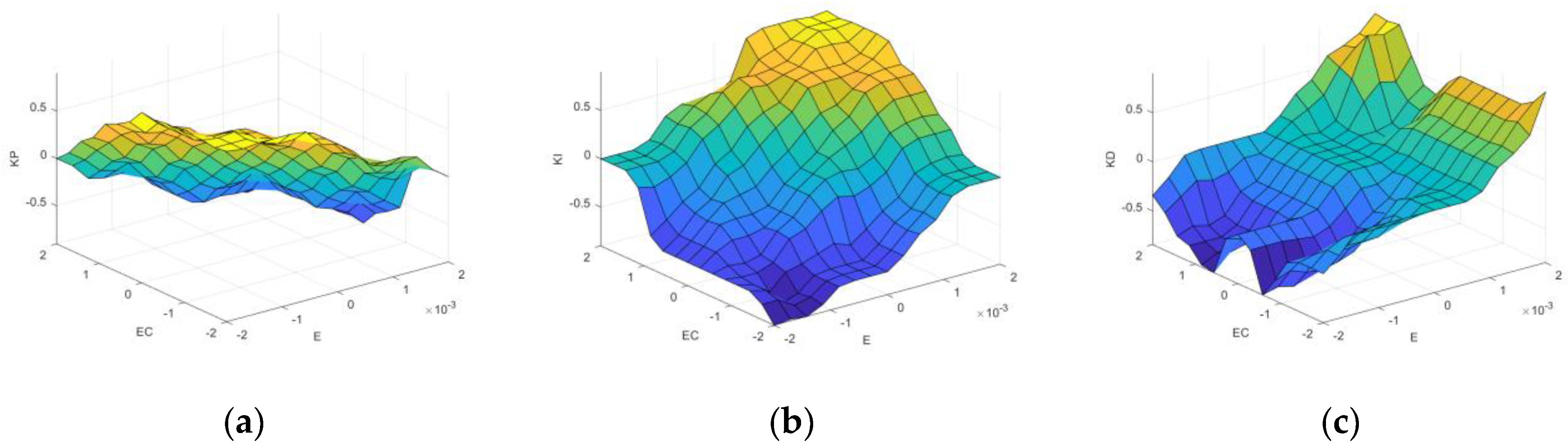
, which represents the sum of the affiliation. This ratio is the center of mass of the fuzzy set A, which represents the center position of the fuzzy set, which is the exact output value after defuzzification. Through the above five steps, the structure of a fuzzy inference system (FIS) for fuzzy control was constructed using MATLAB R2023a’s FuzzyLogicDesigner toolbox. The process generates a fuzzy inference output surface map of the system outputs
, as shown in
Figure 10, which is capable of querying the tuned values of the PID parameters for any given input value.
3.4. Simulation Results
As shown in
Figure 11, for Simulink simulation, the input force of the system acts directly on the cantilever beam equation of state, and the displacement of the cantilever beam is used as the input for the neural network to recognize. And the neural network outputs the classified signals, and at the same time, the displacement and the classified signals are input into the expectation estimation algorithm, which outputs the estimation signals of the step force, and the classified signals are inputted into the fuzzy PID control algorithm, which generates different PID parameters. PID parameters, the displacement output of the cantilever beam is converted to the expected estimated displacement as the signal source of PID control, and the control force output from the PID calculation is then superimposed with the input force to act on the cantilever beam system to complete the control action.
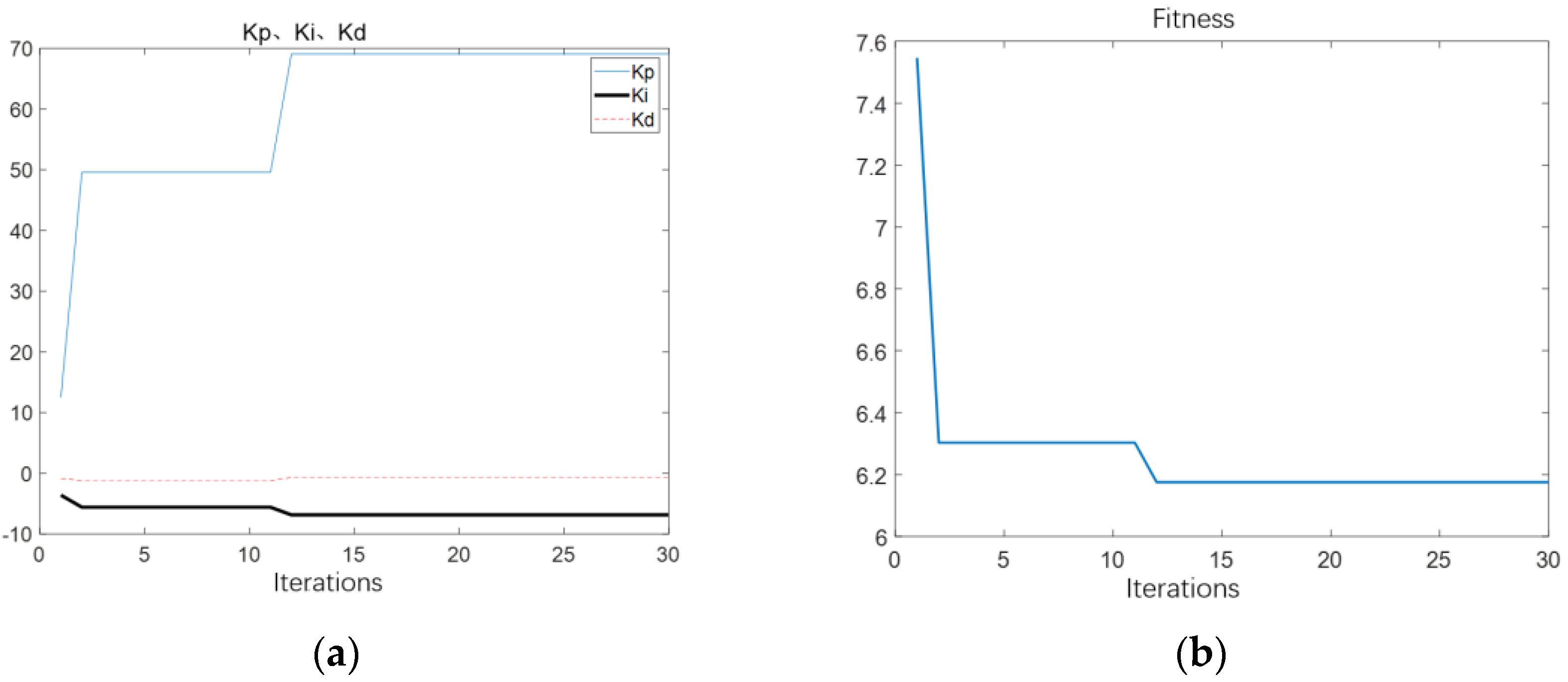
As shown in
Figure 12, for the particle swarm optimization effect, 30 iterations were carried out,
Kp,
Ki, and
Kd changed gradually with the iteration, and remained almost unchanged at the later stage, indicating that the optimum was reached. At this time,
Kp,
Ki, and
Kd are taken as 69.54, −7.95, and −0.43, respectively, and the fitness function was also gradually reduced to unchanged.
As shown in
Figure 13, for the simulation results, it can be seen from the PID control simulation graph that the step tracking effect is better, and no oscillation overshoot appears. Although its ability to suppress impulse and vibration is stronger than that of fixed parameter PID control, there are still some displacement peaks.
From the simulation results, it can be seen that the system is stabilized under the action of fuzzy PID control, and its overshooting amount, adjustment time, and maximum error are all smaller than those of traditional PID control, and its control performance is better than that of the traditional PID control method.
The application of the fuzzy PID control algorithm in this study effectively shortens the adjustment period of the system, realizes a more rapid stabilization of the system, and significantly enhances the stability performance of the system. The optimization of the traditional PID controller by introducing fuzzy logic not only improves the dynamic response characteristics of the control system but also enhances its robustness in the face of parameter changes and external perturbations.
4. Experiments
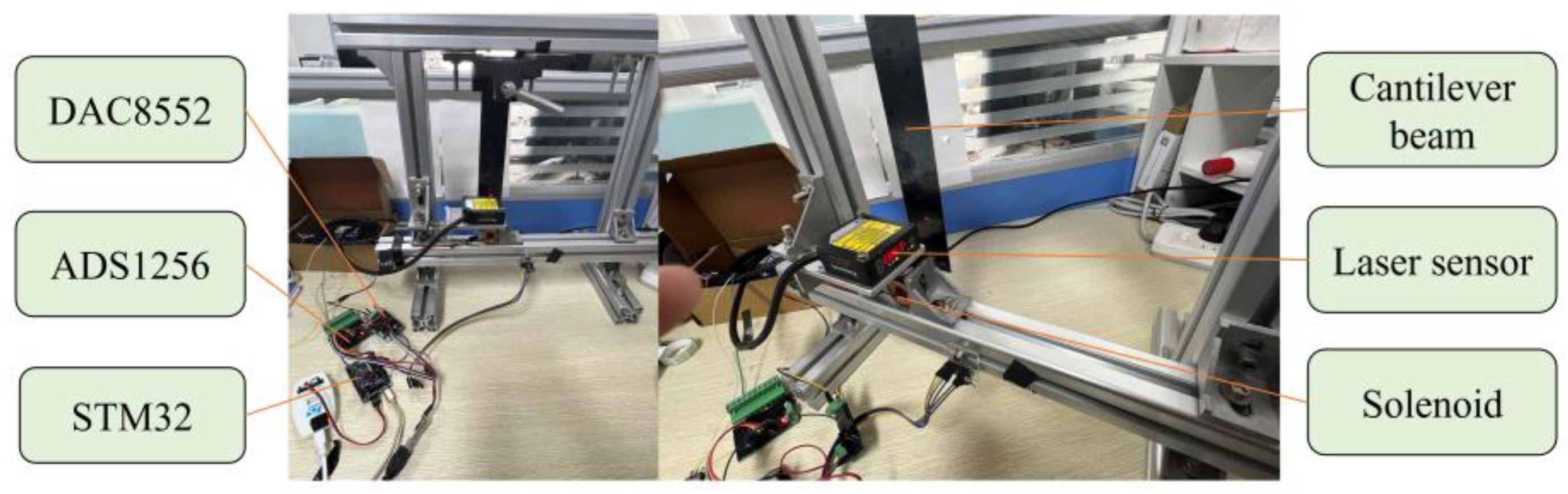
The schematic diagram of the cantilever beam thrust measurement system is shown in
Figure 14. The system mainly consists of a cantilever beam, a fixed fixture, an aluminum alloy frame, a microthrust detection unit, a feedback control unit, a position measurement unit, and a standard force generating unit cum microthrust generating unit. The system adopts the STM32H743 microcontroller module as the core of computing and processing, and FreeRTOS, a real-time system, as the scheduling system.
The overall system is shown in
Figure 15. The cantilever beam is suspended in the air by the fixture fixed on the beam, and the permanent magnet is adsorbed at the bottom midpoint of the free end of the cantilever beam. The electromagnetic coil is aligned with the permanent magnet and fixed on the beam, and the direction of the force is the same as the direction of the cantilever beam oscillation. And the force between the electromagnetic coil and the permanent magnet serves as a push force and a control force. The laser displacement sensor is fixed above the electromagnetic coil to measure the bottom displacement of the cantilever beam.
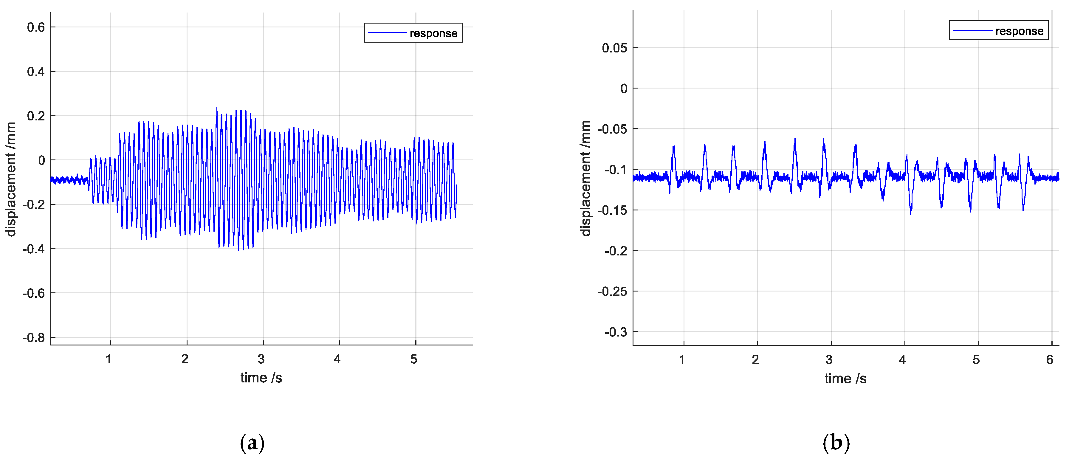
In the thrust calibration study, to ensure generality, we focus on the steady-state response of the thrust. Ideally, the measured steady-state signal should exhibit a step characteristic. Therefore, a synthetic step signal is used for testing in the experiment, and impulse disturbances are simulated by hand-tapping the desktop. After the system is built, the data set acquisition is carried out. When the electromagnet applies force, the cantilever beam vibrates under the force. As shown in
Figure 16a, the vibration of the cantilever beam within each step is characterized by attenuation oscillation, and the attenuation rate is slow, and the oscillation persists, which affects the measurement accuracy, and
Figure 16b shows the step response under fixed-parameter PID control, and it can be seen that the overshooting and the oscillation are large. As shown in
Figure 17a, the cantilever beam under the impulse interference shows attenuation oscillation, the decay rate is slow, and the oscillation persists for a long time, affecting the measurement accuracy.
Figure 17b shows the impulse response under fixed-parameter PID control, and it can be seen that the oscillation is larger, affecting the measurement accuracy.
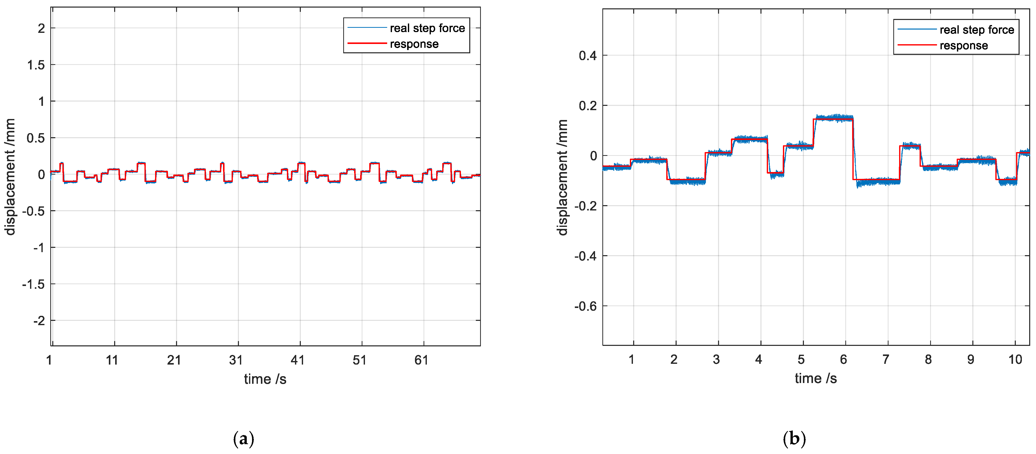
The cantilever beam was loaded with step and impulse signals as the applied force of the thruster and external impulse disturbances, respectively, to test whether the algorithm could suppress the impulses quickly enough to stabilize the cantilever beam. The response of the system to the microthrust is shown in
Figure 18, where the red line indicates the expectation of the estimation algorithm, which is intended to estimate the applied step microthrust, and the blue line indicates the response of the system when the control algorithm is employed.
Figure 18a shows the fixed-parameter PID control, where the system is in uninterrupted oscillations with large overshoots of the step oscillations, and the impulses can hardly be suppressed, making thrust measurements impossible. It shows that the fixed-parameter PID control has difficulty in meeting the multi-state control of the cantilever beam, which can neither track the step better nor shield the impulse of the impulse better.
Figure 18b is the effect of the fuzzy PID control of the ordered step, where the step tracking effect is better, there is almost no overshooting, and the impulse oscillation is smaller, and the amount of the overshooting is controlled within 10%, and the stabilizing time is shortened to less than 0.2 s, and the impulse oscillation is reduced to about 22% of the original one, which basically meets the thrust measurement around, and basically meet the needs of thrust measurement. In
Figure 18c, for the fuzzy PID control stochastic step effect, impulse overshooting is smaller, impulse can be better suppressed, and the oscillation phenomenon of the system has a strong inhibition, with better control accuracy and stability, for the thrust calibration to provide good conditions.
Compared with the traditional PID control algorithm, as shown in
Table 5, from the perspective of overshoot, the fixed-parameter PID will have an overshoot of about 23%, while the fuzzy PID overshoot is 4%, which shows that the addition of fuzzy logic can effectively reduce the overshoot problem that is prone to occur in traditional methods. However, this improvement will actually slow down the response speed: the fixed-parameter PID only takes 0.21 s to reach a stable state, the segmented type needs to increase to 0.26 s, and the fuzzy PID takes the slowest 0.28 s. This shows that there is a restrictive relationship between overshoot suppression and response speed; that is, the higher the algorithm complexity, the smoother the dynamic response. For the control effect of impulse interference, the fixed-parameter PID can only reduce the amplitude to 71% of the original, which is a weak effect, while the fuzzy PID can reduce the amplitude to 27% of the original, which is a strong effect.
In terms of anti-interference ability, the fixed-parameter PID is not handled well, while the fuzzy PID performs better. The fixed-parameter PID has difficulty in filtering out high-frequency interference, especially in the sensor noise frequency band; fuzzy PID enhances the system damping characteristics through real-time parameter adjustment, which is equivalent to introducing adaptive low-pass filtering, and can automatically identify and filter out interference signals.
The control effect of particle swarm optimized fuzzy PID control algorithm under random step, random time, and random impulse loading is shown in
Figure 19b as a zoomed-in figure, from which it can be seen that the control algorithm still achieves the goal of suppressing the impulse and following the step quickly under random loading.


