Article

Design and Optimization of a Large-Air-Gap Voice Coil Motor with Enhanced Thermal Management for Magnetic Levitation Vibration Isolation in a Vacuum †

1
School of Electrical Engineering and Automation, Harbin Institute of Technology, Harbin 150001, China
2
Suzhou Research Institute, Harbin Institute of Technology, Suzhou 215104, China
*
Author to whom correspondence should be addressed.
This paper is an extended version of our paper published in Mu, J.; Zhang, H. Design and Optimization of Large Air-Gap Voice Coil Motor for Application in Magnetic Levitation Platform. In Proceedings of the 11th Chinese Symposium on Magnetic Levitation Technology and Vibration Control, Changsha, China, 4–7 August 2023.
Actuators 2025, 14(6), 301; https://doi.org/10.3390/act14060301
Submission received: 16 May 2025 / Revised: 8 June 2025 / Accepted: 17 June 2025 / Published: 19 June 2025
(This article belongs to the Special Issue Advanced Theory and Application of Magnetic Actuators—2nd Edition)

Abstract

:
This study presents the design, optimization, and experimental validation of a large-air-gap voice coil motor (LAG-VCM) for high-precision magnetic levitation vibration isolation in vacuum environments. Key challenges arising from a large air gap, including pronounced leakage flux and a reduced flux density, were addressed by employing the equivalent magnetic charge method and the image method for the modeling of permanent magnets. Finite element analysis was applied to refine the motor geometry and obtain high thrust, low ripple, and strong linearity. To mitigate the severe thermal conditions of a vacuum, a heat pipe-based cooling strategy was introduced to efficiently dissipate heat from the coil windings. The experimental results demonstrate that the optimized LAG-VCM delivers a thrust of 277 N with low ripple while effectively maintaining coil temperatures below critical limits for prolonged operation. These findings confirm the suitability of the proposed LAG-VCM for vacuum applications with stringent requirements for both a large travel range and stable, high-force output.

1. Introduction

Vibration isolation platforms are extensively used in the testing and environmental simulation of spacecraft. Traditional vibration isolation approaches include mechanical spring vibration isolation [1,2], air spring vibration isolation [3,4], and hydraulic vibration isolation [5,6]. However, these conventional solutions typically exhibit relatively high stiffness, implying that even a small displacement can result in substantial force changes. Consequently, they often struggle to satisfy the high-precision, low-disturbance requirements demanded by emerging space applications. Magnetic levitation vibration isolation has recently gained significant attention due to its unique advantages: It is contactless, features high precision, is long-lived, and features low maintenance [7,8,9,10]. Due to the low stiffness inherent in magnetic levitation systems, force changes with displacement are minimized, thereby more effectively isolating the tested object from external disturbances. Moreover, unlike air-based solutions, magnetic levitation can operate in vacuum environments without concerns regarding gas leakage or supply.
During their design and manufacturing, space telescopes require a series of tests to verify their functionalities. The China Space Station Telescope (CSST) needs to test its optical imaging system under vacuum microgravity conditions, necessitating the design of a gravity compensation vibration isolation system that can operate in a vacuum. Air spring isolation is unsuitable for vacuum conditions [11], and the high stiffness of mechanical spring isolation systems does not allow for precise positioning; meanwhile, magnetic levitation isolation systems, due to their low stiffness and lack of gas leakage, effectively meet these requirements. Figure 1 presents the basic configuration of the vibration isolation platform, which mainly consists of a permanent magnet array-type magnetic levitation gravity compensator [12], voice coil motors, and a support frame. The gravity compensator and the voice coil motor’s armature are connected to the object being tested, where the gravity compensator plays a passive role in gravity compensation, and the voice coil motor actively isolates vibrations and compensates.
In recent years, there has been considerable research on voice coil motors for magnetic levitation and vibration isolation. In [13], two different structures of voice coil motors designed for magnetic positioning devices were analyzed using finite element analysis (FEA) to study the impact of various parameters on thrust. The results ultimately demonstrated a 40% difference in thrust between the two motors with the same volume. In [14], a voice coil motor capable of generating constant thrust without energy input was proposed. The motor’s stiffness with constant thrust was optimized by altering the core iron shape, achieving a constant thrust of 20.9 N and saving 23 W of power consumption. The authors of [15] proposed a three-degree-of-freedom spherical voice coil motor for robotic joints, achieving a tilt range of ±30° along the X and Y axes and a rotation range of 360° around the Z axis using annular magnets and multiple coils. In [16], a two-degree-of-freedom voice coil motor was proposed, with the magnetic field analyzed using the equivalent current method, achieving a prototype thrust of 7.8 N and a torque of 30 mN·m.
The existing literature has primarily focused on voice coil motors with small air gaps and low thrust. Given the displacement range required by the object under testing and considering the manufacturing and assembly errors inherent in large test platforms, the voice coil motor designed in this study requires a larger mechanical air gap to meet displacement needs within allowable errors. However, when the air gap is large (≥4 mm), the leakage flux significantly increases, which reduces the air-gap flux density and complicates the motor design for high-thrust applications. Furthermore, operating in a vacuum environment makes thermal management more difficult, since convective cooling is virtually absent. These factors demand a specialized LAG-VCM design capable of handling both electromagnetic and thermal constraints. This study targeted the design optimization of voice coil motors under large air-gap conditions [17,18,19,20,21,22].
In this study, a large air-gap voice coil motor was designed and optimized to achieve high thrust, low ripple, and precise vibration isolation under vacuum conditions. The methodology leverages the equivalent magnetic charge approach and finite element optimization to address the inherent challenges of increased leakage flux, a reduced air-gap flux density, and stringent thrust requirements resulting from the large gap. Additionally, a heat pipe-based thermal management strategy was proposed to maintain acceptable winding temperatures in a vacuum environment, where convective cooling is absent. The experimental results confirm that the optimized LAG-VCM meets the targeted thrust capacity, exhibits low ripple, and demonstrates reliable thermal performance, thereby validating its suitability for high-precision, continuous-operation vibration isolation applications.

2. Structure and Magnetic Field Analysis of the LAG-VCM

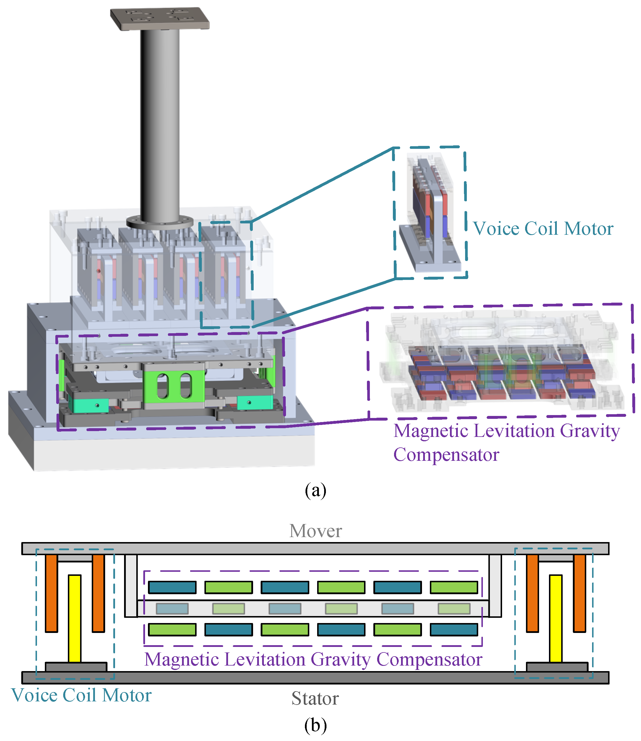
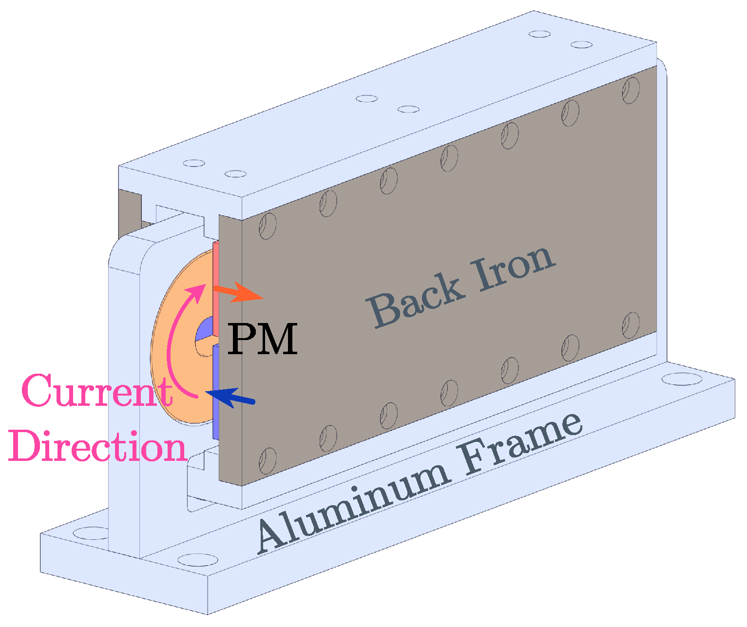
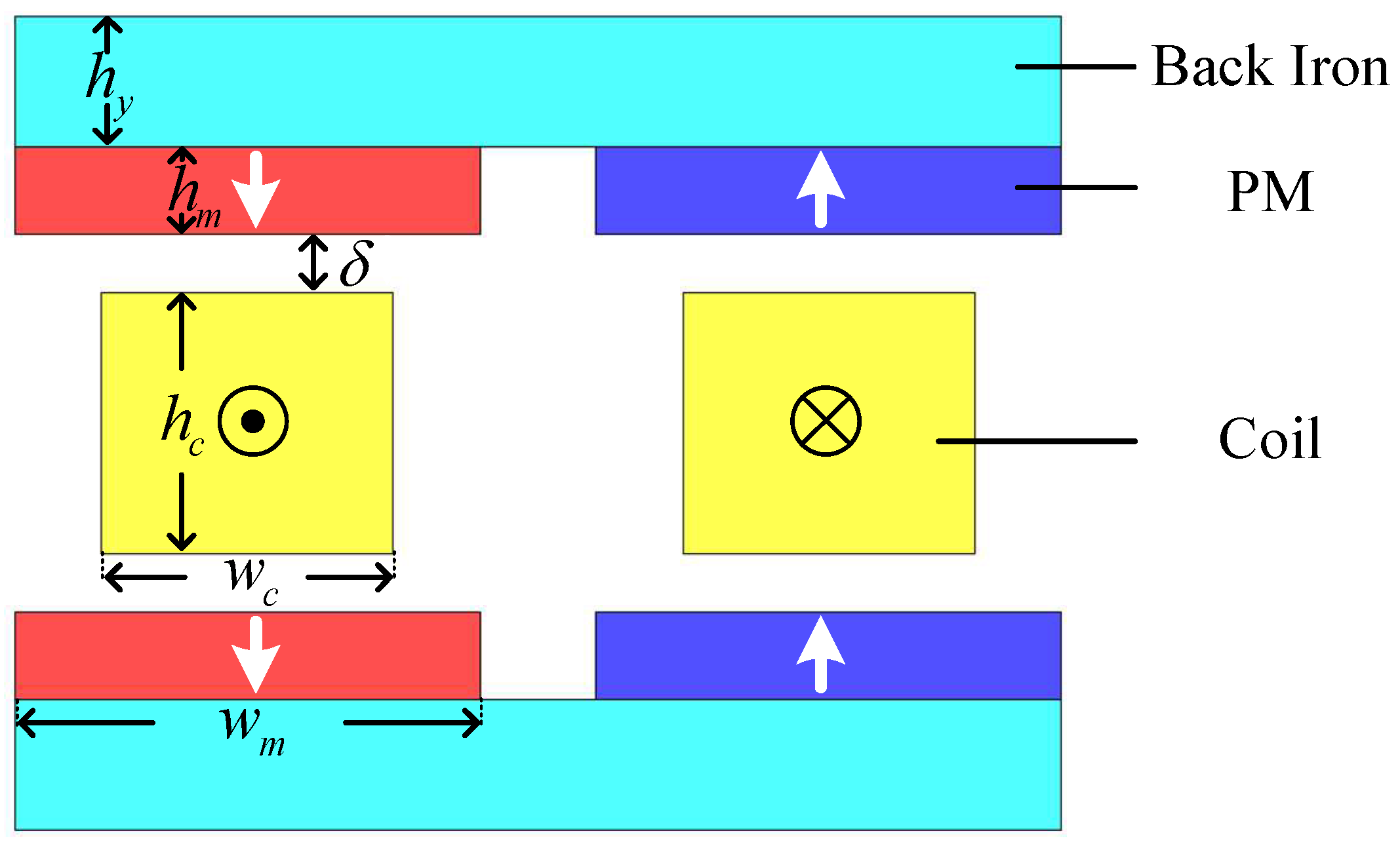
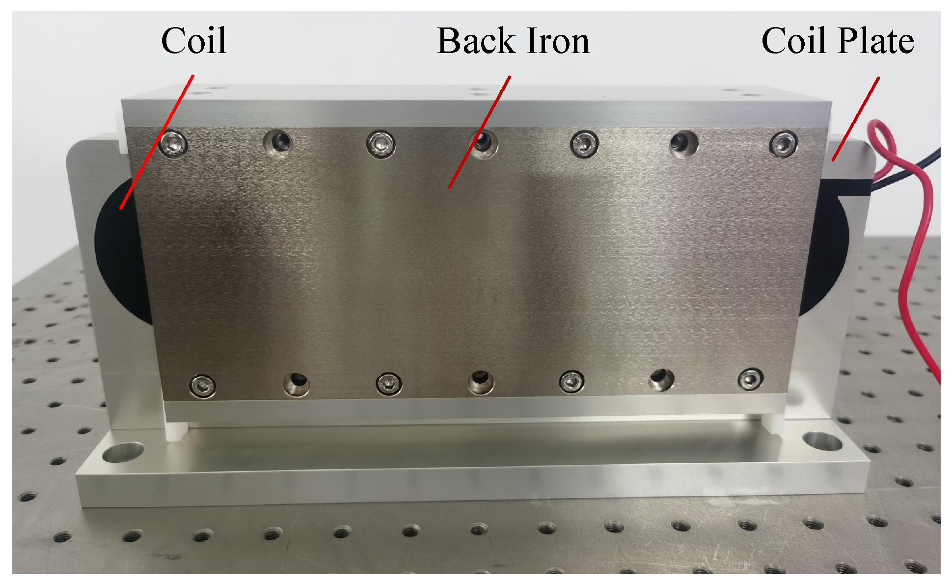
2.1. The Structure of the LAG-VCM

The proposed actuator is a flat-type linear voice coil motor (VCM), as shown in Figure 2. The two red and blue horizontal arrows indicate the magnetization directions of the permanent magnets, and the pink curved arrow denotes the direction of current flow. This actuator employs an active magnetic configuration. The mover is electrically passive (wiring-free), which eliminates cable interference with an optical test setup. Moreover, the coil produces joule heating when energized, and in a vacuum, the lack of convective heat transfer severely impairs cooling. Since the optical test system is highly temperature-sensitive, the coil is mounted on the stator to enable direct conduction to the base cooling block, thus preventing thermal disturbance to the optics. The design requirements of the VCM are summarized in Table 1.

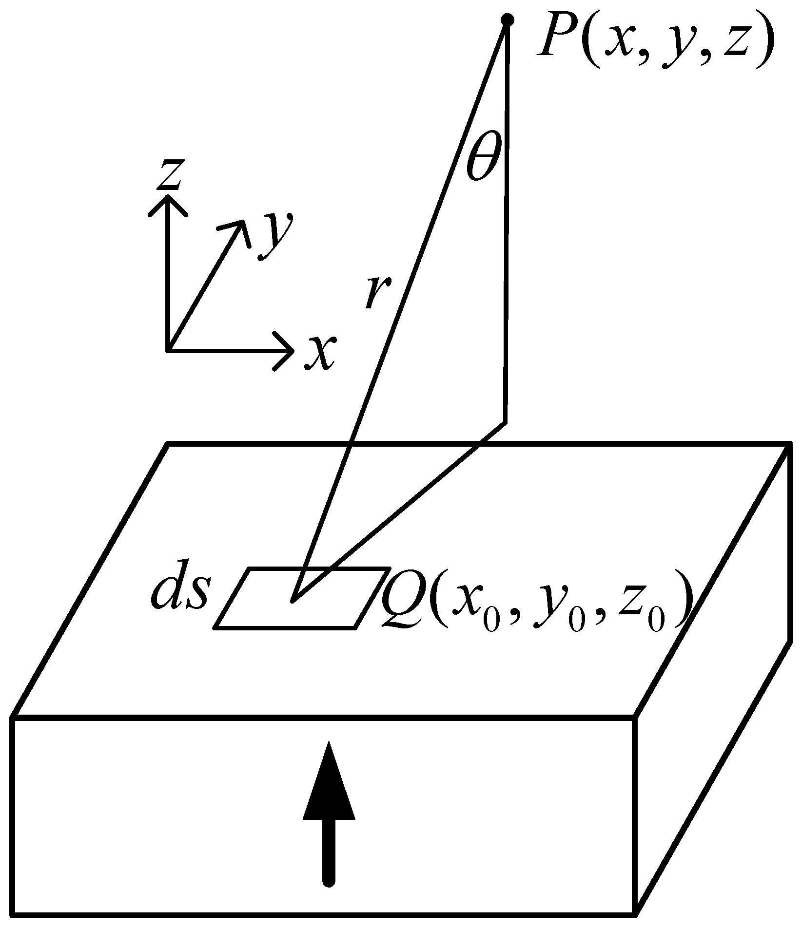
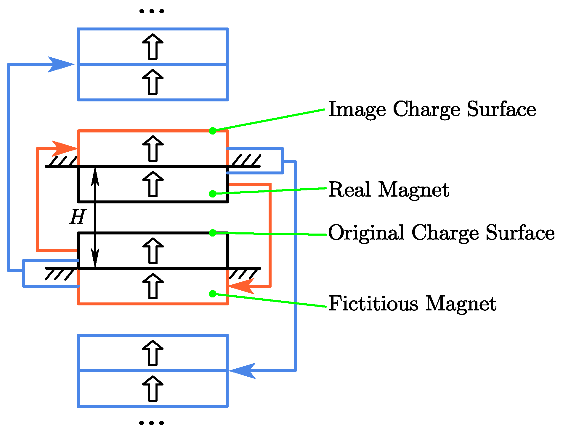
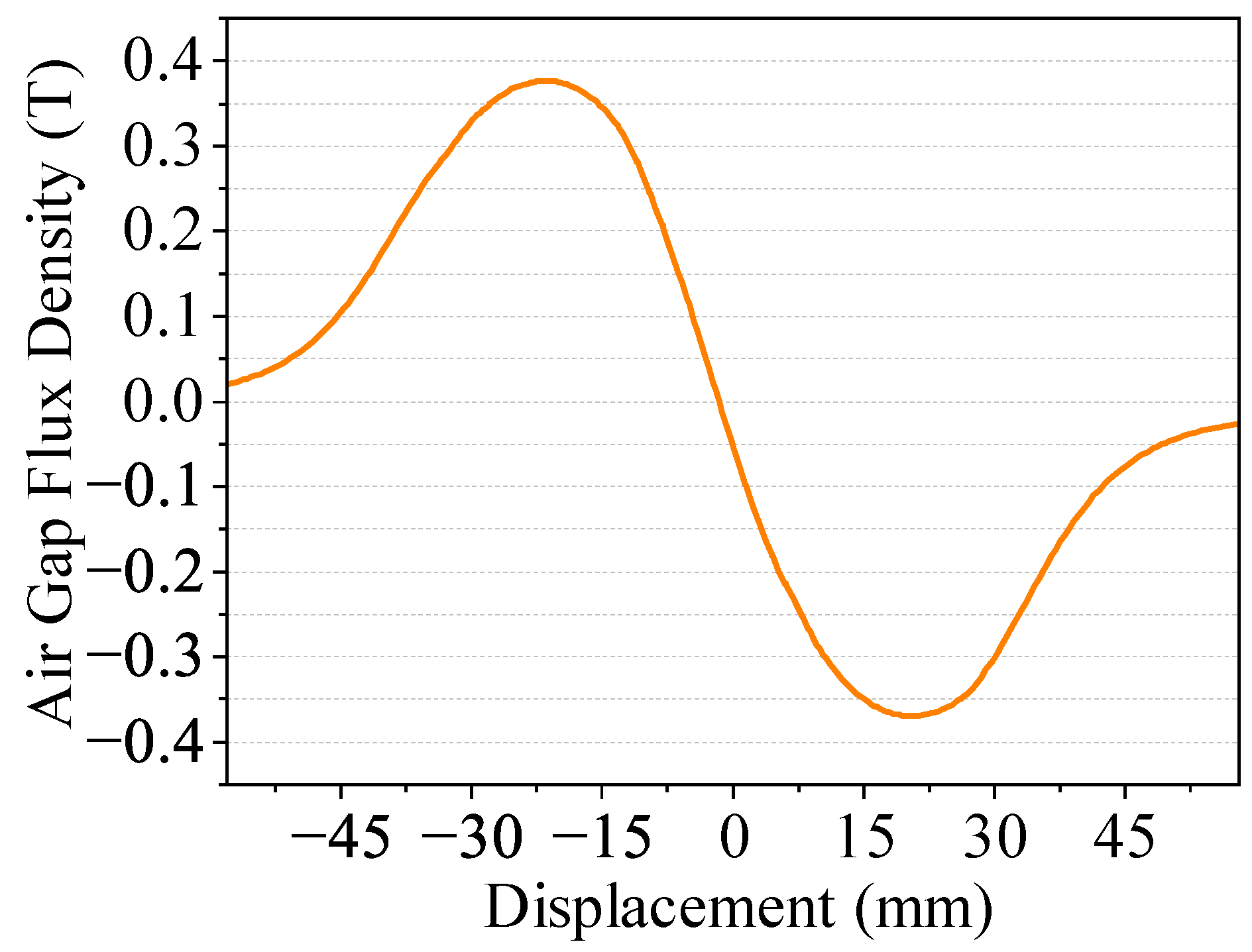
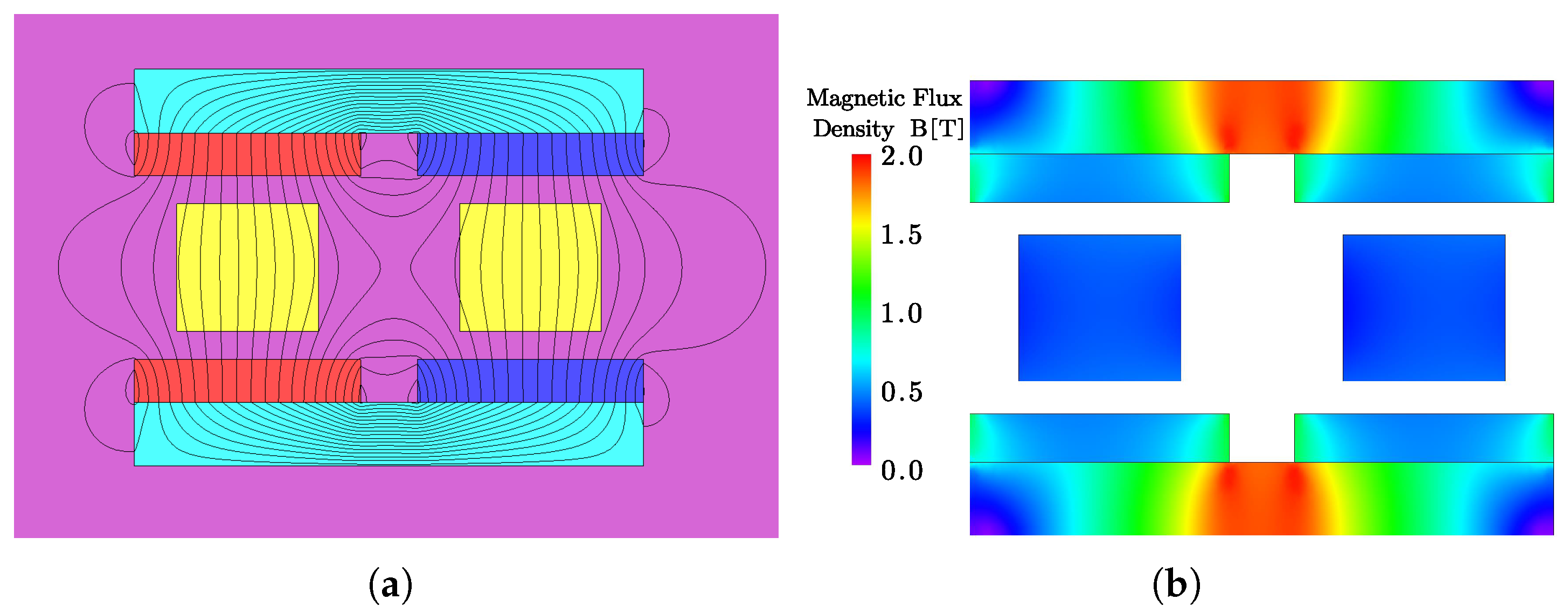
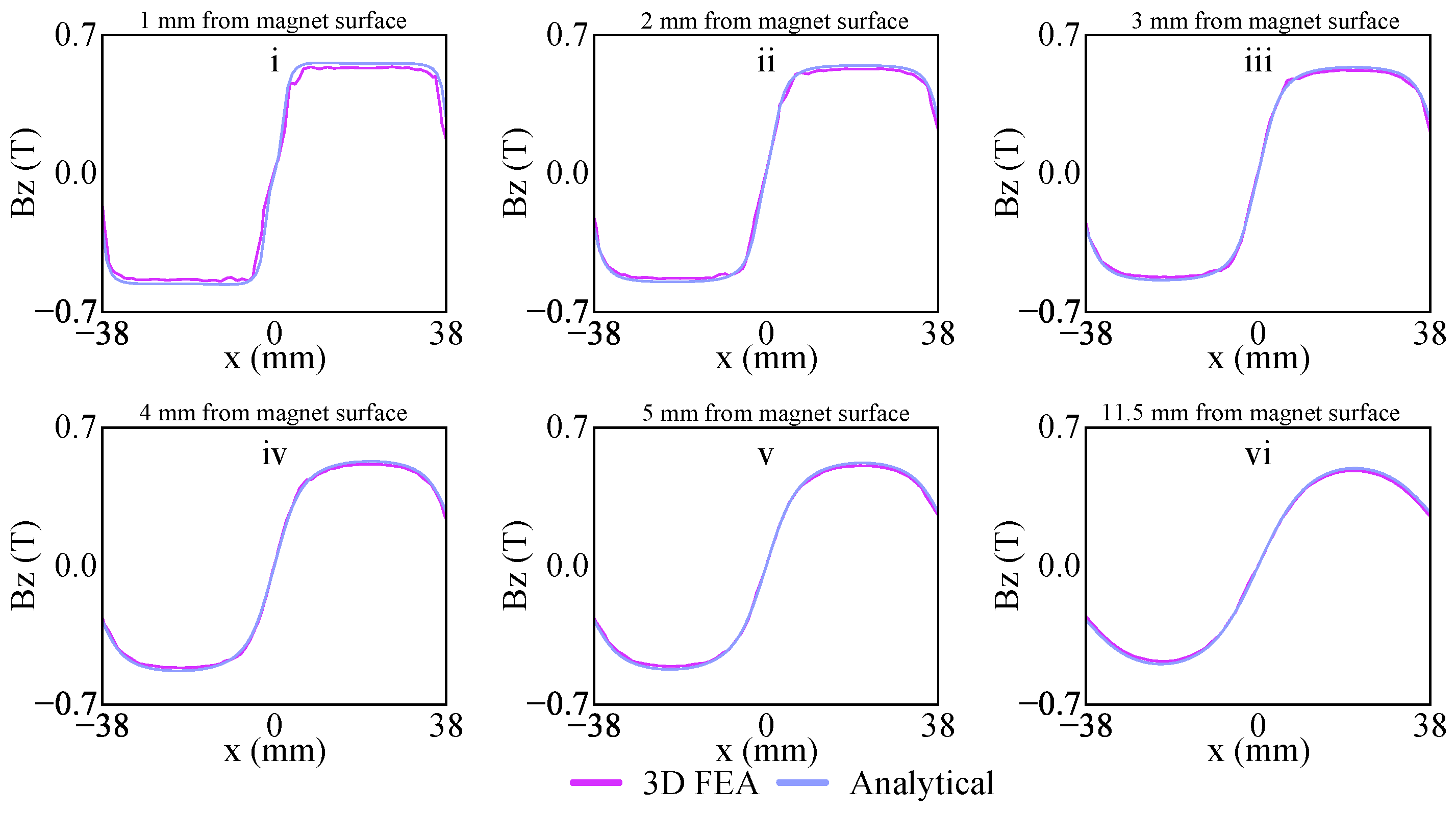
2.2. Magnetic Field Analysis of the LAG-VCM

The equivalent magnetic charge method is a widely utilized theoretical tool in magnetic field analysis and is particularly effective for handling permanent magnets with complex geometries and magnetization distributions [23,24,25]. This method simplifies the computation of magnetic fields by representing the magnetization within the material as equivalent surface and volume magnetic charges. Specifically, the equivalent magnetic charge method leverages the magnetization vector M to transform the internal magnetic field problem of a permanent magnet into an analogous problem of electric charge distribution in electrostatics. By introducing the volume magnetic charge density ρ m and surface magnetic charge density σ m , the method facilitates an analytical solution for the magnetic field.
Substituting H = φ m and B = μ 0 ( H + M ) into Maxwell’s divergence equation · B = 0 , we derive the Poisson equation for the scalar magnetic potential φ m :
2 φ m = · M
To solve the Poisson equation, the Green’s function method is employed, allowing the scalar magnetic potential to be expressed as a combination of volume and surface integrals as follows:
φ m ( e ) = 1 4 π V · M ( e ) e e d v + 1 4 π S M ( e ) · n e e d s
where e denotes the position vector of the observation point; e represents the position vector of the source point; and n is the unit normal vector on the surface S.
To further simplify the expression, we define the volume magnetic charge density ρ m and the surface magnetic charge density σ m as follows:
ρ m = · M
σ m = M · n
Substituting ρ m and σ m into the scalar magnetic potential expression and then substituting φ m into the expression for the magnetic flux density B , we obtain the following expression for the magnetic flux density generated by the permanent magnet in free space:
B ( e ) = μ 0 4 π V ρ m ( e ) e e e e 3 d v + μ 0 4 π S σ m ( e ) e e e e 3 d s
For uniformly magnetized permanent magnets, the internal magnetization M is constant, leading to a volume magnetic charge density of zero as ρ m = · M = 0 . Consequently, the expression for the magnetic flux density simplifies to
B ( e ) = μ 0 4 π S σ m ( e ) e e e e 3 d s
Figure 3 illustrates the equivalent magnetic charge model for a vertically magnetized permanent magnet. In this model, the vertically magnetized permanent magnet is equivalently represented by two magnetic charge surfaces located on the upper and lower surfaces of the magnet. Here, P ( x , y , z ) denotes the observation point in free space at which the magnetic flux density is to be evaluated; Q ( x 0 , y 0 , z 0 ) denotes a representative source point on the magnet face; d s denotes the infinitesimal surface element; r is the scalar distance from the source point Q to the field point P; and θ is the angle between r and the z axis. Assuming that the origin of the coordinate system is positioned at the geometric center of the permanent magnet, the magnetic flux density produced in free space by a rectangular permanent magnet can be expressed as follows:
B ( e ) = μ 0 M s 4 π k = 1 2 ( 1 ) k b b a a e e e e 3 z k d x d y
where M s denotes the residual magnetization of the permanent magnet; a and b represent the semi-lengths of the permanent magnet in the x and y directions; and z k indicates the z coordinates of the two magnetic charge surfaces.
Specifically, the expression for the z component of the magnetic flux density is given by
B z ( x , y , z ) = μ 0 M s 4 π i = 1 2 j = 1 2 k = 1 2 ( 1 ) i + j + k tan 1 G x , y , z , x i , y j , z k
where the function G is defined as
G x , y , z , x i , y j , z k = x x i y y j z z k 1 x x i 2 + y y j 2 + z z k 2 1 / 2
This expression accurately describes the Z component of the magnetic flux density in space by superimposing the contributions from different magnetic charge surfaces.
In the LAG-VCM configuration, there are ferromagnetic boundaries on both sides. These boundaries substantially influence the magnetic field generated by the permanent magnets. To account for this effect analytically, the image method can be employed. The image method replaces the influence of a perfectly ferromagnetic boundary by introducing a series of fictitious image magnetic charges located behind the boundary plane such that the boundary condition of zero normal flux leakage at the ferromagnetic interface is satisfied [26].
Figure 4 shows a schematic of the image method for two rectangular permanent magnets between two parallel ferromagnetic plates. In the figure, the black rectangles labeled ’Real Magnet’ denote the actual, uniformly magnetized PM, with its top/bottom faces carrying the original magnetic surface charge; the orange outlines indicate the first image magnets that enforce the boundary condition at the closest ferromagnetic plate; the blue outlines represent the second image magnets, generated by reflecting the first image about the opposite ferromagnetic boundary, and so on; the distance between the two ferromagnetic surfaces is denoted by H.
Mathematically, if B original ( x , y , z ) denotes the magnetic flux density produced by the real magnet in free space, then under the constraint of two infinite, perfectly ferromagnetic ( μ r ) plates separated by a distance H, the total flux density in the air gap can be written as the superposition of the original field and all image fields. Specifically, one obtains the following:
B ( x , y , z ) = B original ( x , y , z ) + i = 1 B original x , y , z + i H + B original x , y , z i H B image ( x , y , z )
where for each i 1 , the pair z ± i H denotes the ith-order image magnets.
Thus, Equation (10) compactly expresses the composite air gap field B ( x , y , z ) as the infinite sum of the original PM field and its images. In summary, the equivalent image method allows us to account for ferromagnetic boundary conditions analytically by replacing the iron plates with an appropriate series of fictitious magnets.
In the early stages of LAG-VCM design, it is often sufficient to estimate the volume-average air-gap flux density within the coil winding region rather than computing its full spatial distribution. Specifically, one defines the following:
B ¯ δ = 1 V coil V coil B ( x , y , z ) d V
where V coil denotes the effective volume occupied by the coil windings.
By evaluating B ¯ δ via computed integrals, one obtains a thrust estimate directly from the Lorentz force relation:
F L = N B ¯ δ I L eff
where N is the total number of turns in the coil, I is the coil current, and L eff is the effective length (i.e., the equivalent 2D depth).
By narrowing down the magnet dimensions, coil turn count, and yoke dimensions via these analytical expressions, the parameter space for subsequent FEM optimization is drastically reduced, accelerating convergence toward the final design.
In summary, the equivalent magnetic charge method represents the magnetization vector M by equivalent magnetic charge distributions and, using integral expressions augmented by the image method when ferromagnetic boundaries are present, yields an analytical solution for the local field B ( x , y , z ) . These analytical tools provide a rapid, reliable means to calculate the air-gap flux density and estimate the motor thrust. They guide the selection of preliminary magnet, coil, and yoke dimensions, accelerate early tradeoff studies, and deliver a robust theoretical foundation for the design and optimization of the LAG-VCM.

3. Finite Element Analysis and Optimization of the LAG-VCM

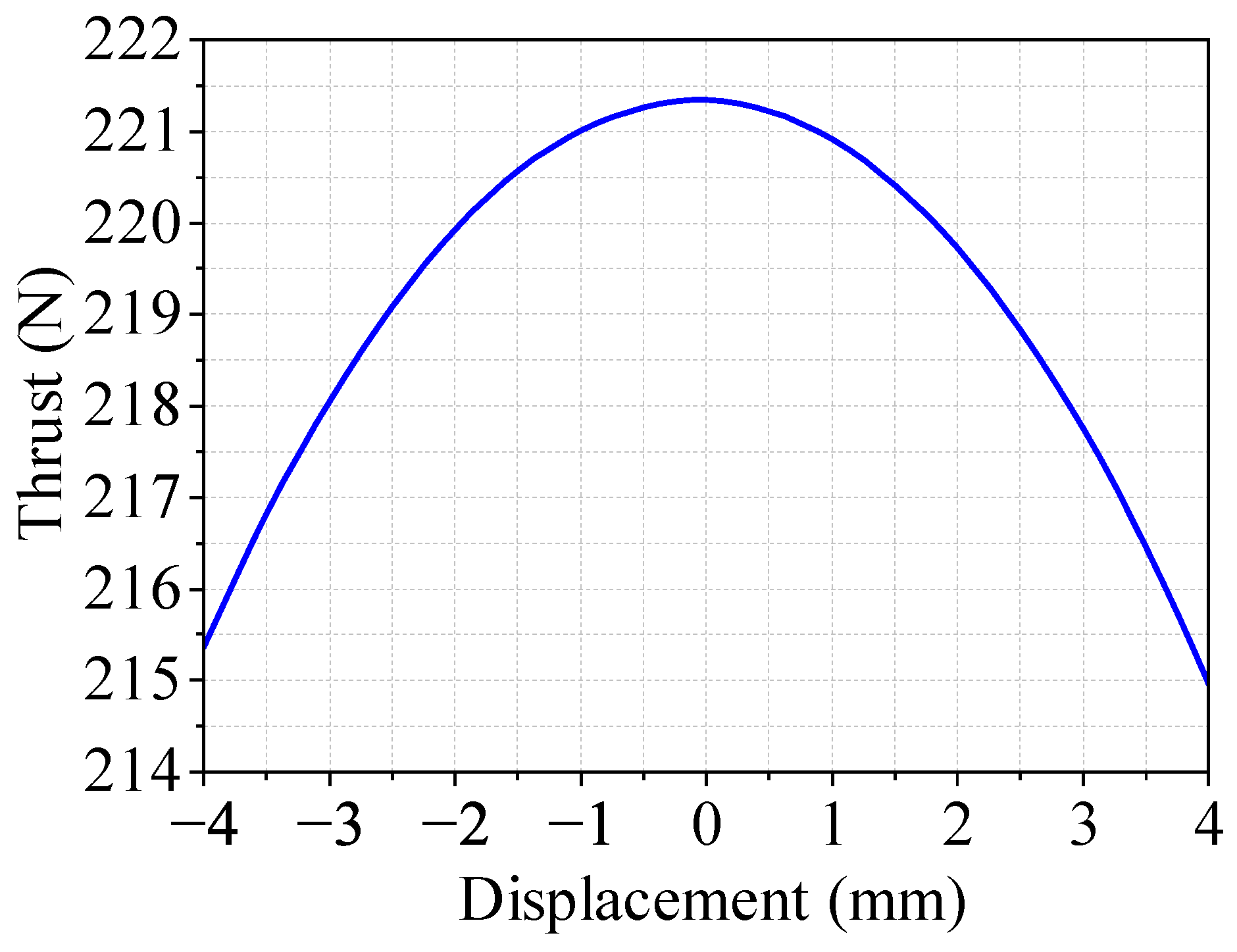
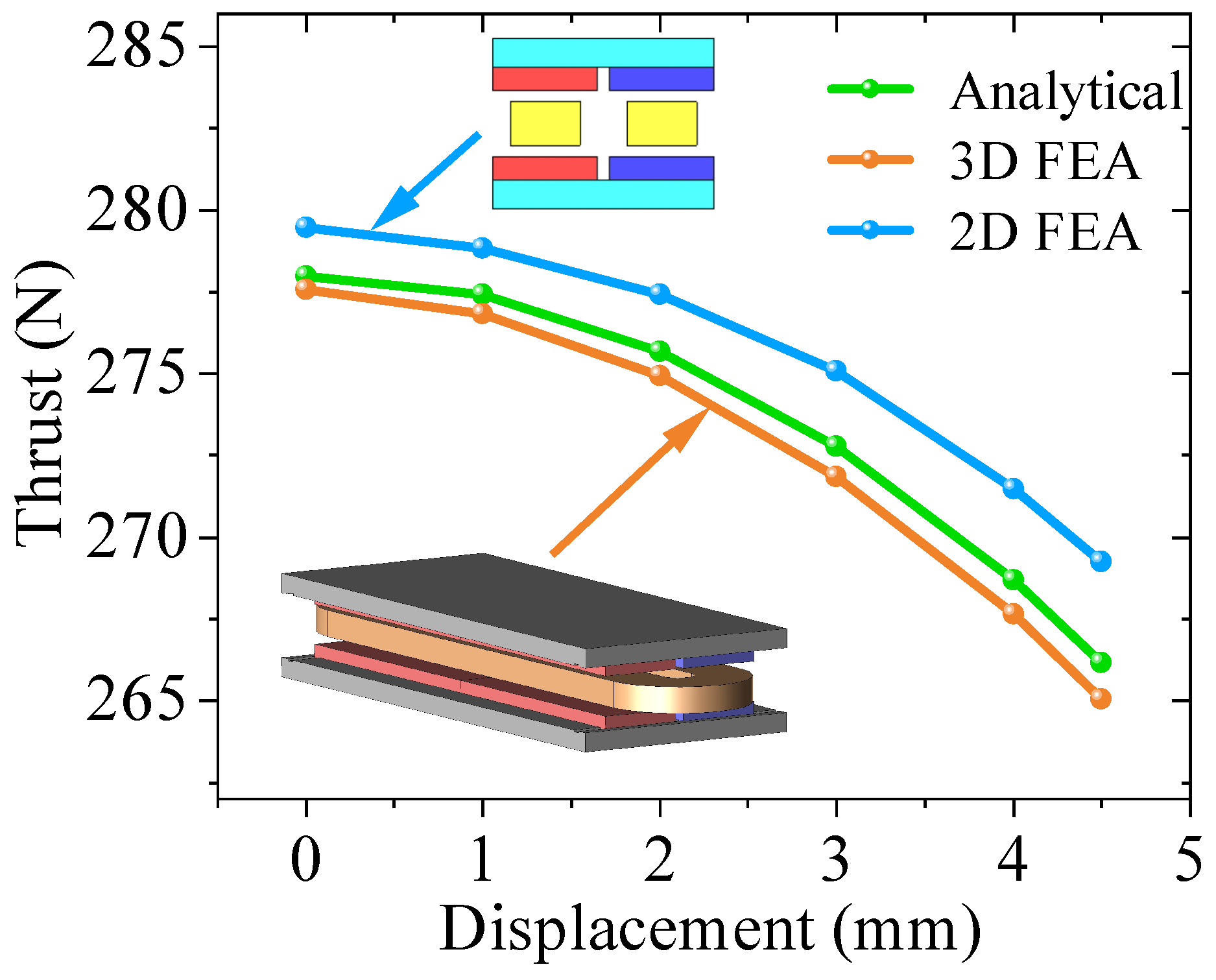
3.1. Finite Element Analysis Validation of the LAG-VCM

A 2D finite element analysis model was established using finite element analysis software, with its geometry and initial parameters derived from an electromagnetic design incorporating analytical field solutions, as shown in Figure 5. In this model, w m denotes the permanent magnet width, and h m denotes its height; w c denotes the coil width, and h c denotes its height; h y denotes the yoke height, and δ denotes the electromagnetic air-gap length. An equivalent depth L eff = 230 mm was assigned in the out-of-plane direction so that Lorentz force calculations in 2D could be directly mapped to the full 3D motor.
Because the analytical approach cannot account for iron core saturation effects, finite element analysis is required to accurately capture nonlinear material behavior and truly reflect motor performance. However, full 3D FEA of the entire parameter space is computationally prohibitive during optimization due to the excessive mesh size and long solution times involved. Therefore, 2D FEA was employed for rapid parametric optimization, while full 3D FEA was reserved for final validation and comparison once the candidate geometries had been narrowed down.
Figure 6 illustrates the thrust variation with position when the rated current was applied to the coil. The maximum thrust of 221.3 N occurred at the coil’s center position and gradually decreased with increasing coil displacement. At the center position, the thrust did not reach the design target.
The magnetic flux density in the middle of the motor’s air gap is depicted in Figure 7. At the air-gap centerline, the maximum flux density is 0.35 T, which is lower than the preset air-gap flux density in the electromagnetic design. This is due to the significant leakage flux associated with the large equivalent air gap and possible saturation in the yoke.
The distribution of flux lines in the voice coil motor is shown in Figure 8a. The flux lines primarily form a closed magnetic circuit through the permanent magnet–air-gap–yoke path, but significant leakage occurred between adjacent magnets. This is mainly due to the large equivalent air gap of the voice coil motor, which should be reduced in subsequent optimization.
The magnetic flux density map of the voice coil motor is presented in Figure 8b. It shows a certain degree of saturation at the center of the yoke, which weakened the motor’s thrust and increased the thrust ripple. In future optimization, the height of the yoke should be increased to mitigate this saturation. Furthermore, it can be observed that the saturation is concentrated primarily in the region between the two permanent magnets, whereas the yoke sections closer to the lateral ends—farther away from the magnets—exhibit only minimal saturation. In applications where weight reduction and high dynamic response are critical, a trapezoidal yoke profile (thicker in the central region and thinner toward the edges) could be employed to reduce mass and cost [27]. However, for the LAG-VCM, structural integrity, overall mechanical stability, and ease of assembly are of greater importance. Therefore, the chosen optimization approach is intended to uniformly increase the entire yoke height.

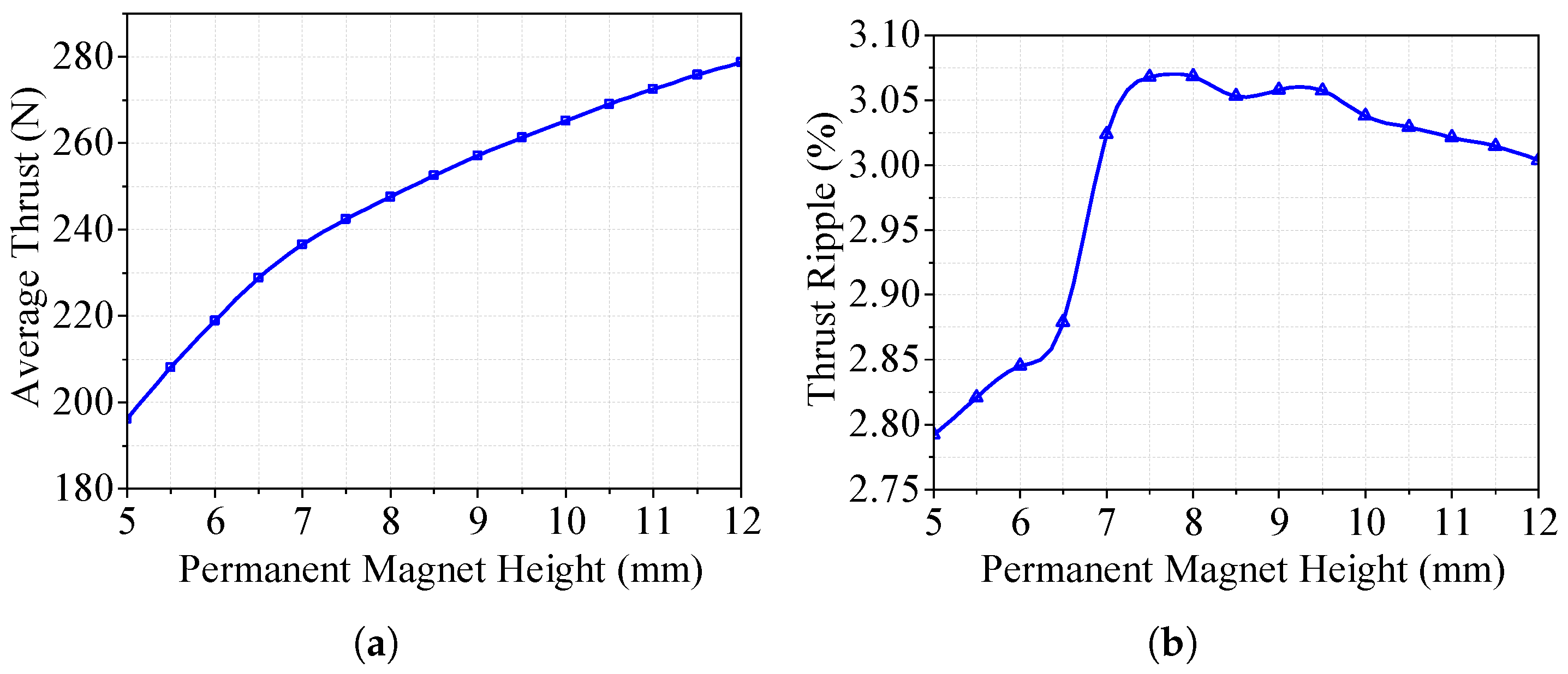
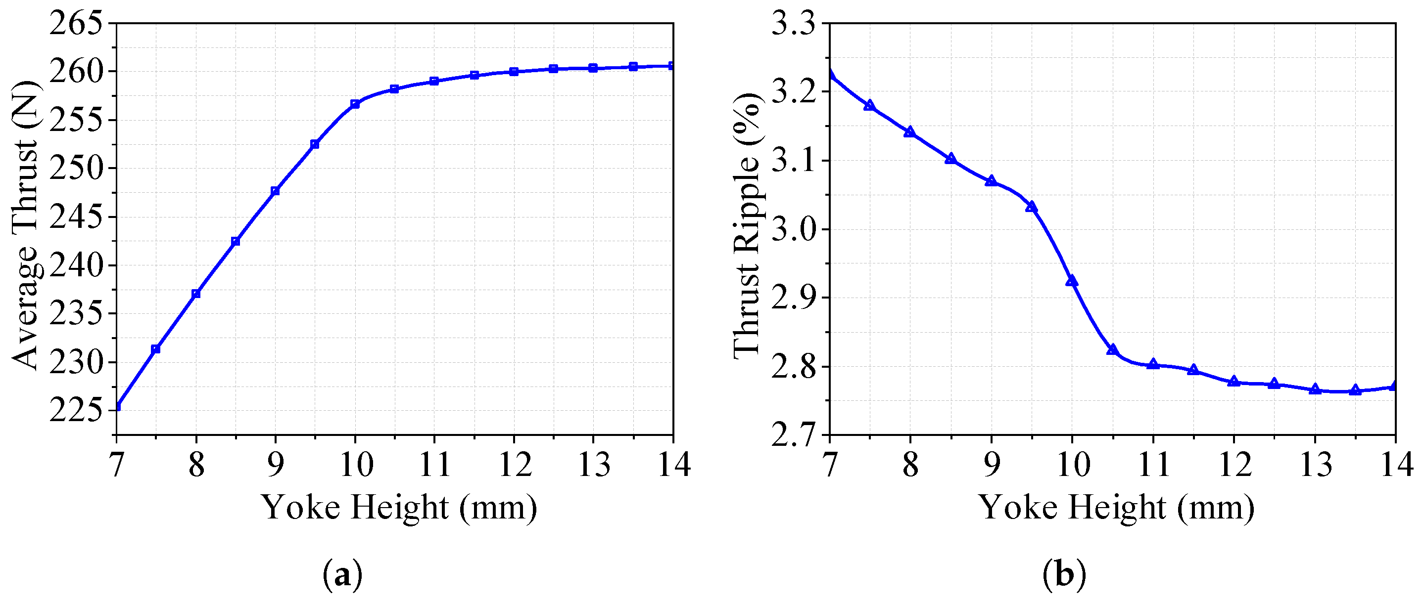
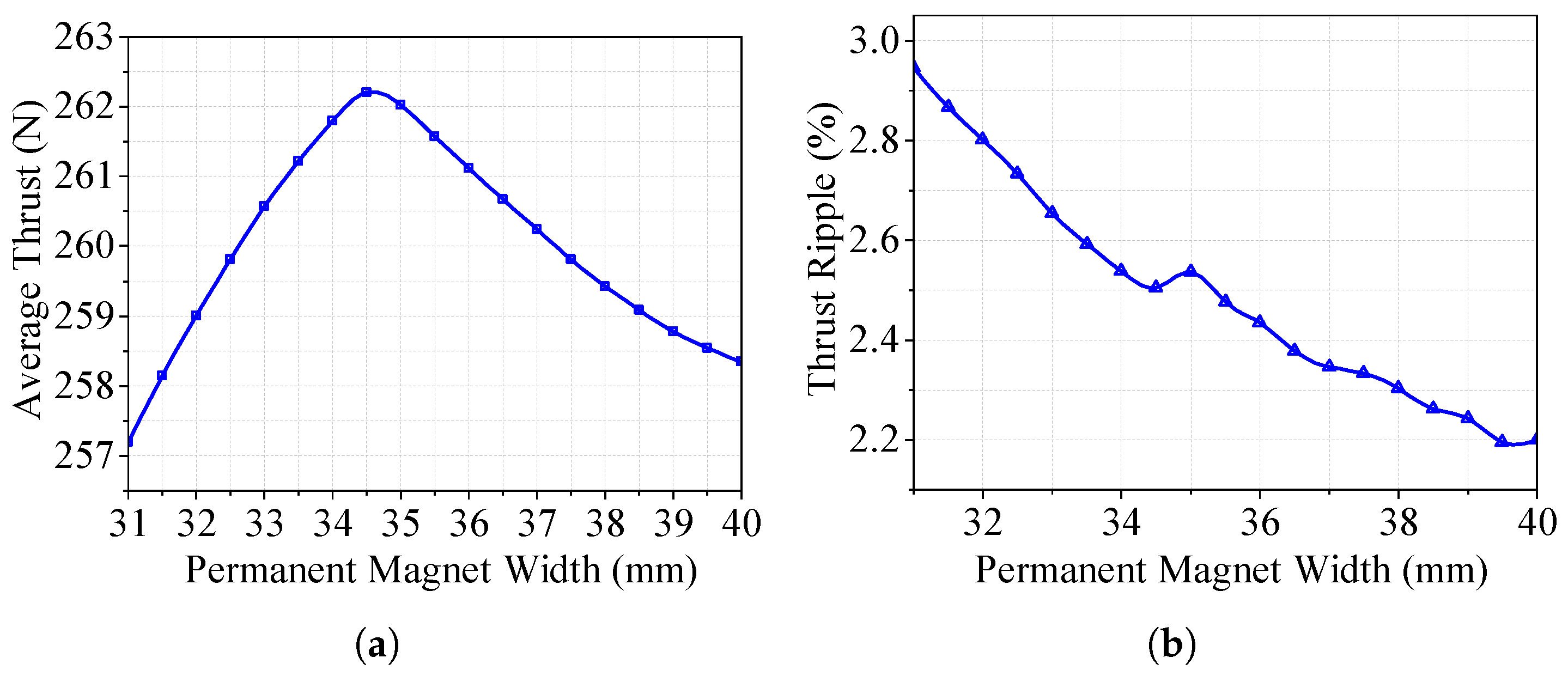
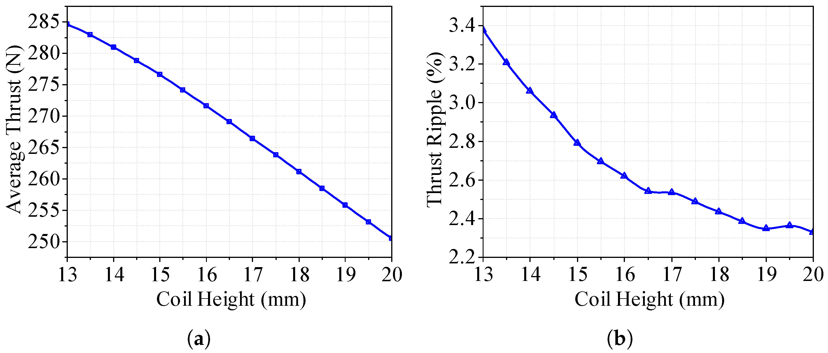
3.2. Finite Element Optimization of the LAG-VCM

Finite element optimization was carried out using parameter scanning to analyze the impact of different parameters on the motor’s thrust and thrust ripple. When increasing the air-gap flux density to enhance the motor’s thrust, the aim was to minimize the armature mass for an improved dynamic response while considering practical manufacturing costs.
To quantitatively evaluate the variations in thrust over the motor’s stroke, two indices are defined. Let F ( x ) be the thrust at axial position x, with x [ x min , x max ] . The average thrust F ¯ is obtained by sampling F ( x ) at discrete intervals and computing the arithmetic mean as follows:
F ¯ = 1 N i = 1 N F x i
where x i denotes the ith sample point within the travel range.
The thrust ripple γ is calculated using the maximum and minimum thrust values observed over the same stroke:
γ = F max F min F max
with F max typically appearing around the center of the stroke and F min occurring near the stroke extremes.
First, the effect of the permanent magnet height on the average thrust and thrust ripple of the voice coil motor was analyzed. The relationship between the average thrust and the height of the permanent magnets is shown in Figure 9a. The motor’s thrust increased with the height of the permanent magnets due to the increased magnetic potential and the consequent increase in the air-gap flux density. When the height of the magnets exceeded 7 mm, the increase in thrust slowed due to further saturation of the yoke. The thrust ripple varied with the height of the permanent magnets, as shown in Figure 9b. The thrust ripple initially increased and then stabilizes with increasing height. This is due to increased unevenness in the air-gap flux density caused by saturation, leading to a higher thrust ripple. Considering both the average thrust and thrust ripple, a height of 8 mm was chosen for the permanent magnets.
Changes in yoke height were analyzed in terms of the average thrust and thrust ripple of the voice coil motor. The relationship between the average thrust and yoke height is shown in Figure 10a, where the average thrust initially increased and then stabilized with increased yoke height due to decreasing saturation levels. The relationship between the thrust ripple and yoke height is presented in Figure 10b, where the thrust ripple decreased and then stabilized as the yoke height increased, improving the uniformity of the air-gap magnetic field. Therefore, a yoke height of 11 mm was chosen.
The effect of changing the width of the permanent magnets on the average thrust and thrust ripple was calculated, as shown in Figure 11a,b. Considering subsequent optimization margins and manufacturing costs, a width of 36 mm was chosen for the permanent magnets.
By keeping the coil area and number of turns constant and changing the coil height, the average thrust and thrust ripple were calculated, as shown in Figure 12a,b. As the coil height increased, the average thrust gradually decreased due to the increased equivalent air gap and increased magnetic reluctance in the air gap, leading to a decrease in the air-gap flux density and, consequently, the average thrust. The thrust ripple decreased with increasing coil height as the coil width simultaneously decreased, improving the uniformity of the internal magnetic field and thus reducing the motor thrust ripple. After considering both the average thrust and thrust ripple, a coil height of 15 mm and a width of 24 mm were selected.
To further validate the analytical approach, a series of comparisons were performed between the air-gap flux density predicted by the analytical model—which combines the equivalent magnetic charge method and image method under the assumption of idealized infinitely permeable ferromagnetic boundaries—and the results obtained from full 3D finite element analysis. The 3D FEA model was built using the optimized geometry derived from the 2D FEA optimization. Flux density values were computed at 1 mm, 2 mm, 3 mm, 4 mm, 5 mm, and 11.5 mm from the magnet surface. As shown in Figure 13, the two methods exhibit a high degree of agreement in distribution shape and peak locations, with only minor amplitude differences. Although the analytical model does not account for yoke saturation, the prior optimization of the yoke height minimized saturation effects, resulting in close concordance between the analytical and FEA results. This consistency confirms that the simplified analytical formulation provides an accurate preliminary estimate of the magnetic field distribution in the air gap.
To evaluate the effectiveness of the analytical method in calculating the motor’s electromagnetic thrust, thrust values computed by each method (analytical, 2D FEA, and 3D FEA) were compared at a constant coil current of 5 A at different displacement positions. As shown in Figure 14, the maximum difference between the analytical prediction and the 3D FEA result was only 1.1 N (approximately 0.4%), while the 2D FEA result deviated from the 3D FEA by at most 4.2 N (about 1.5%). All three methods exhibited the same slowly decreasing thrust-vs-displacement trend, demonstrating a high degree of consistency. Notably, the 2D FEA result was consistently higher than both the analytical and 3D FEA results because the 2D model does not account for the out-of-plane decay of the magnetic field, leading to a systematic overestimation of the Lorentz force. Overall, the close agreement among the analytical, 2D FEA, and 3D FEA results confirms the analytical method’s accuracy as a preliminary design tool, with 3D FEA serving as the final validation benchmark.

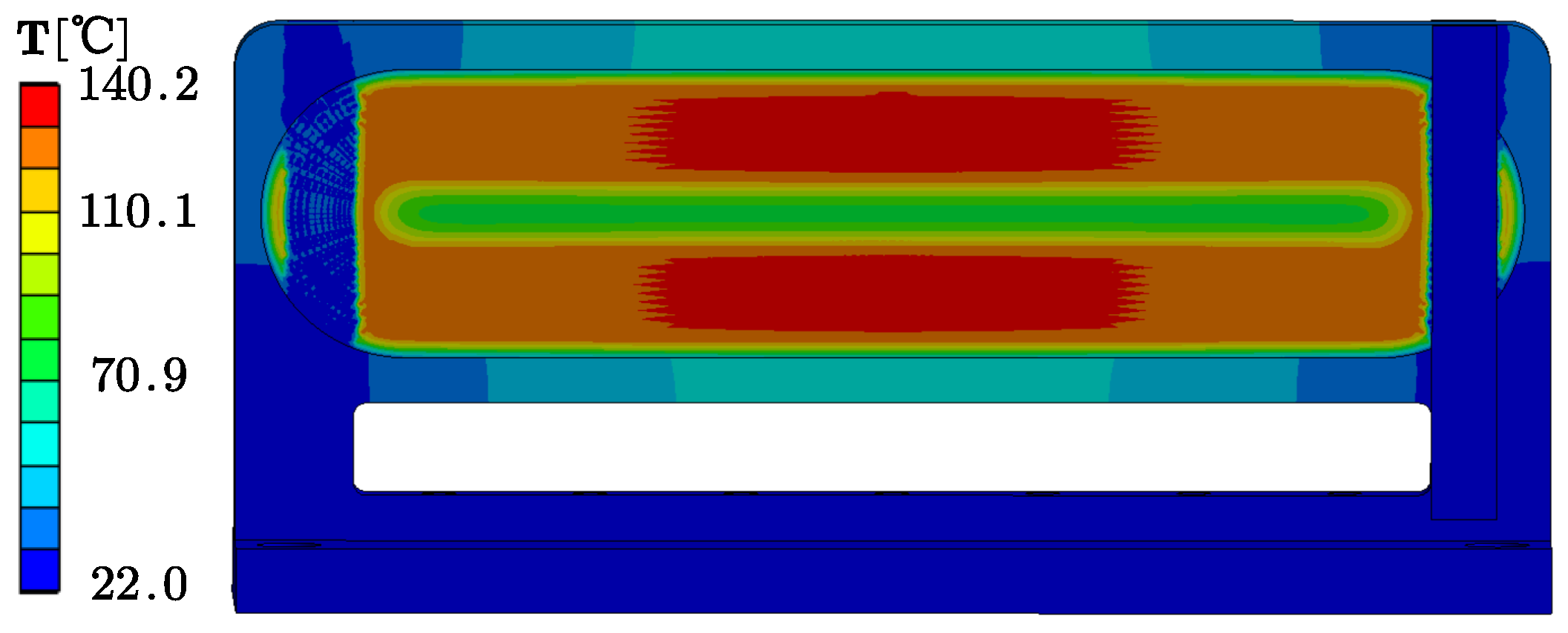
4. Thermal Analysis and a Cooling Strategy for a Vacuum-Operated Voice Coil Motor

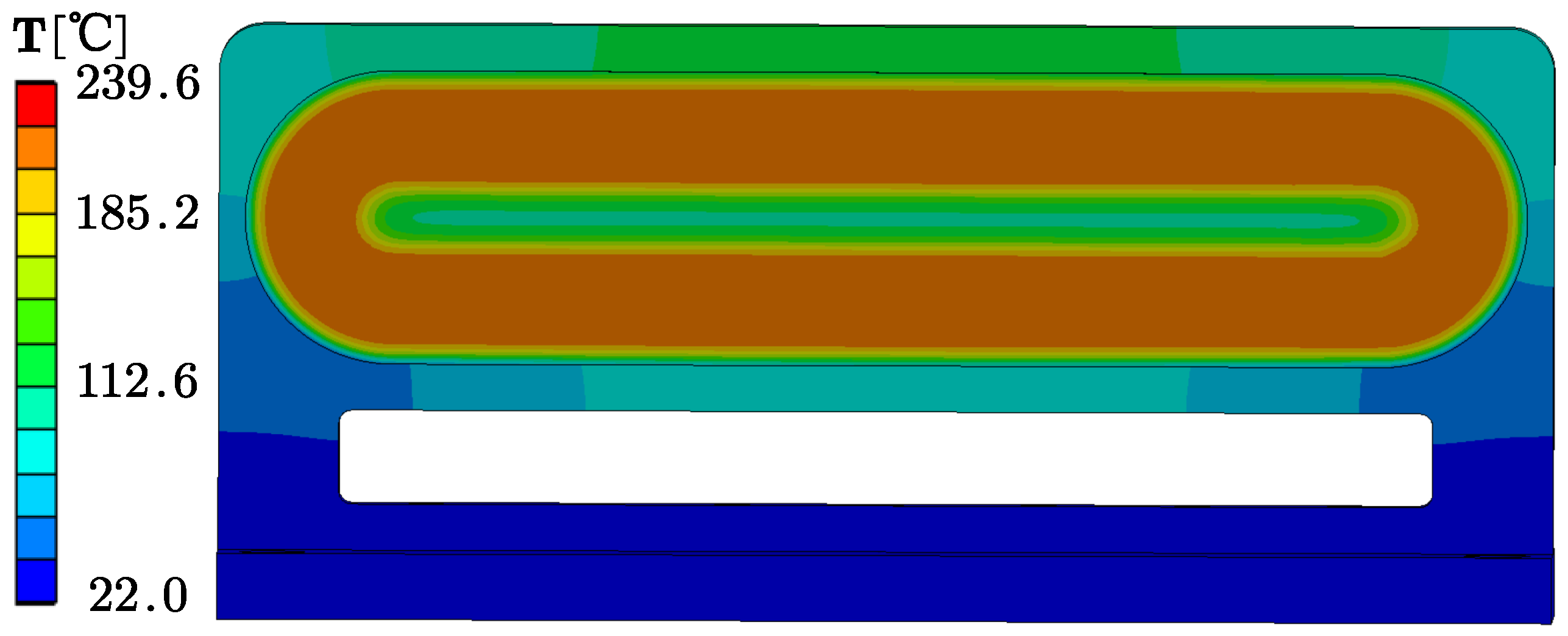
4.1. Introduction and Baseline Analysis

Voice coil motors are widely employed in high-precision and high-thrust applications, such as magnetically levitated isolation platforms. However, when operating in a vacuum, the absence of convective cooling leads to substantial thermal challenges, risking insulation failure and performance degradation. The VCM discussed here comprises copper windings embedded in low-thermal-conductivity (≈0.2 W/(m·K)) epoxy mounted on a 7075 aluminum frame (≈130 W/(m·K)). While epoxy potting enhances mechanical robustness and insulation, it also impedes heat dissipation to the cold plate at the base of the motor, which is maintained at 22 °C.
A three-dimensional finite element model (FEM) was built to assess steady-state heat flow and radiation effects within this vacuum environment. Radiative heat transfer was included using the Stefan–Boltzmann law:
Q rad = ϵ σ A T 4 T env 4
where ϵ is the surface emissivity, σ is the Stefan–Boltzmann constant, and A is the surface area at temperature T facing an environment at T env .
Conduction in each material region is given by
· k T = q
where k is the thermal conductivity, and q the volumetric heat source.
In the copper windings, the joule heat is calculated via
Q = I 2 R ( T ) , R ( T ) = ρ ( T ) L A , ρ ( T ) = ρ 0 1 + α ( T T 0 )
Under a 5 A coil current, the FEM predicts approximately 160 W of resistive heat, causing the winding temperature to climb to around 235 °C in the steady state. This temperature far exceeds the 180 °C rating (Class H) of both the enamel insulation and epoxy. Figure 15 illustrates the hot zone concentrated around the epoxy-encapsulated coil, highlighting a significant temperature gradient from the upper aluminum region (approximately 135 °C) to the base (around 30 °C).

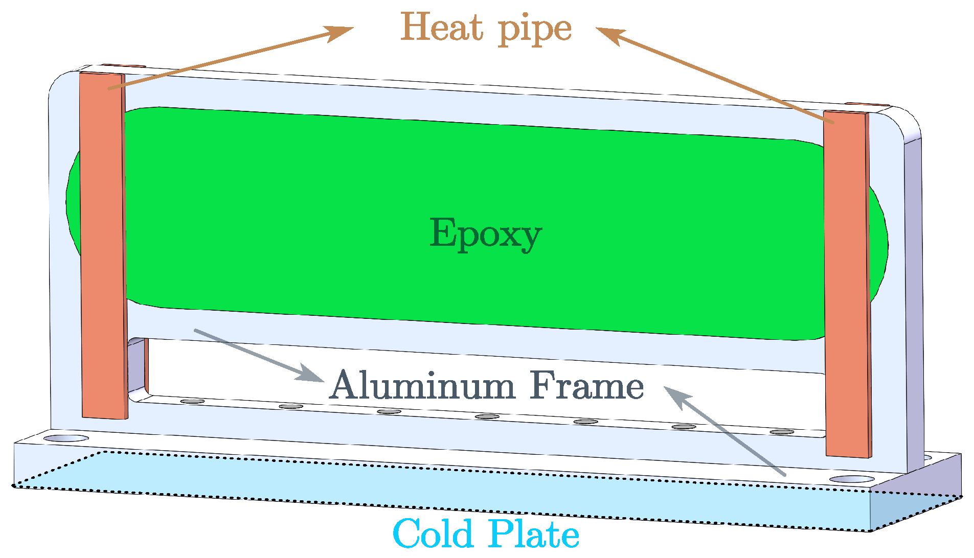
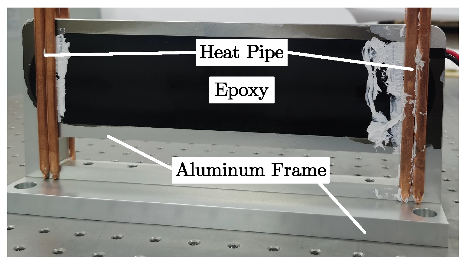
4.2. Proposed Heat Pipe Cooling Enhancement

Because conventional water-cooling plates would encroach on the magnetic gap and reduce the travel stroke, an alternative approach is required. Here, multiple slim heat pipes were bonded along the side surfaces of the epoxy potting and aluminum frame. Heat pipes utilize the evaporation and condensation of an internal working fluid to provide an effective thermal conductivity on the order of 10 4 W / m · K , greatly exceeding that of common metals. By extending from the high-temperature regions near the coil to the cold plate at the motor’s base, these pipes facilitate rapid heat transport without significantly altering the VCM’s mechanical layout.
Figure 16 shows a 3D model of the VCM with the heat pipes attached along the coil’s epoxy region and frame. In the finite element analysis, each heat pipe is treated as an ultra-high-thermal-conductivity strip in the conduction equation, thus establishing a low-resistance path for heat flow.
Rerunning the FEM under the same operating conditions revealed a substantial reduction in the maximum coil temperature—down to approximately 140 °C. Additionally, the improved heat extraction lowered the steady-state coil resistance, decreasing the joule losses from 160 W to around 125 W. The resulting temperature distribution, depicted in Figure 17, remains below the critical 180 °C threshold for Class H insulation.
Overall, this heat pipe arrangement prevents thermal runaway in vacuum conditions, avoids the complexities of a water-cooling loop, and exerts minimal effects on the motor’s air gap and travel range. Each heat pipe can be bonded in place at a relatively low cost, making it a practical and effective means of protecting the VCM’s insulation integrity.
This study has demonstrated that a vacuum-operated VCM within a magnetically levitated isolation platform experiences severe overheating when relying solely on conduction through epoxy and aluminum. Embedding a water-cooling channel near the coil is impractical due to geometric constraints and the platform’s motion requirements. Alternatively, attaching high-thermal-conductivity heat pipes proves highly effective, significantly lowering winding temperatures and preserving the Class H insulation limit.
By combining the finite element modeling of conduction and radiation losses, one can systematically evaluate the VCM’s thermal behavior and optimize the heat pipe configurations. The proposed approach preserves stroke capabilities, minimizes additional mass and complexity, and can be readily adapted to other vacuum-based motor systems.

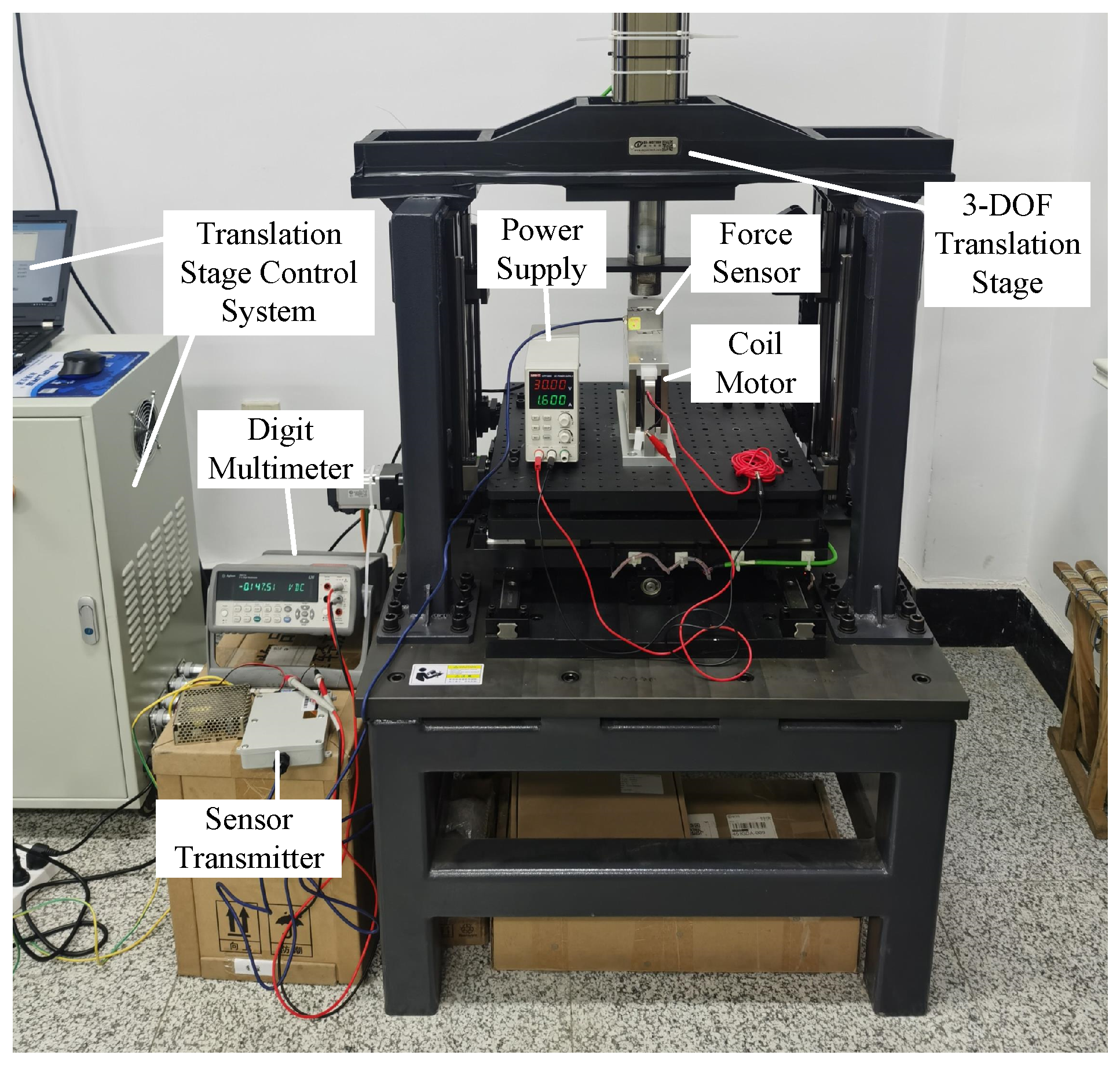
5. The LAG-VCM Prototype and Experimentation

Following the electromagnetic design and finite element optimization, a prototype of the LAG-VCM was manufactured, as shown in Figure 18. The back iron material is S10C (manufactured by Baosteel Group Corporation, Shanghai, China); the permanent magnets are NdFeB (Grade N48H, manufactured by Hangzhou Permanent Magnet Group Co., Ltd., Hangzhou, China); the remaining support structures were manufactured from 7075 aluminum alloy; and the coil is encapsulated with epoxy resin. There is no physical contact between the mover and the stator. The total mass of the mover is 6.95 kg, and the mass of the stator is 2.8 kg. The main parameters of the prototype are given in Table 2.

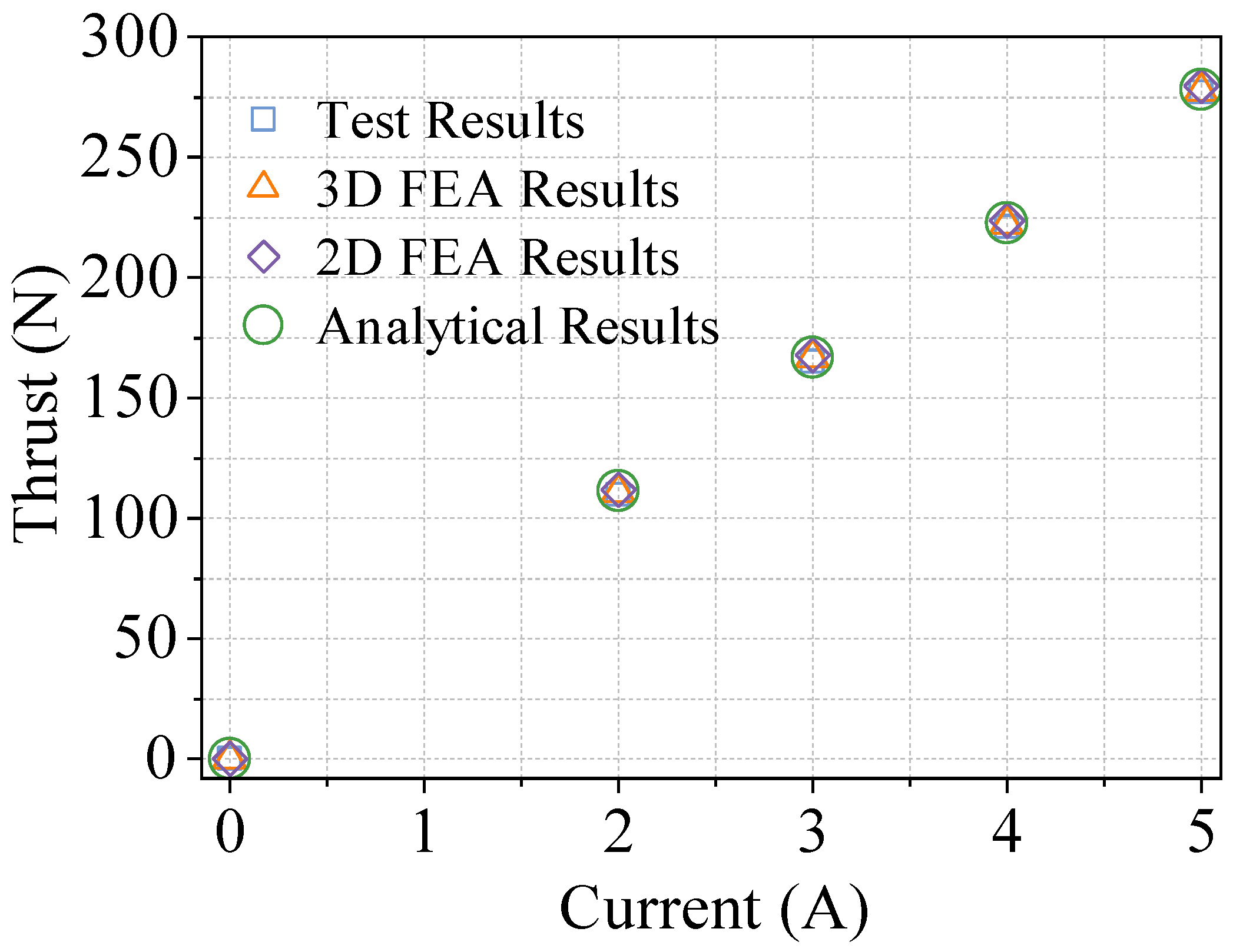
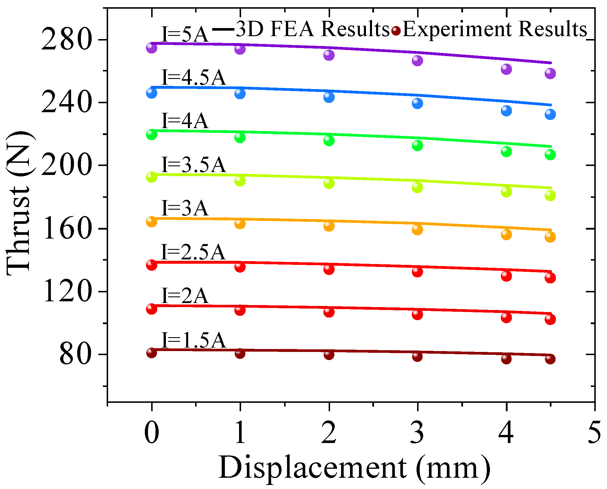
5.1. The Thrust Test of the LAG-VCM Prototype

The platform used for the thrust test of the large-air-gap voice coil motor is illustrated in Figure 19. A three-degree-of-freedom (3-DOF) electrically controlled translation stage facilitates displacement in the direction of the motor’s movement, with a minimum displacement resolution of 0.1 mm. The DC power supply (model UTP1306S, manufactured by Uni-Trend Technology Co., Ltd., Dongguan, China) provides a controllable direct current to the coil of the voice coil motor. A force sensor (a Transcell BAB-20MT device; capacity: 200 N; manufactured by Transcell Technology, Inc., Buffalo Grove, IL, USA) and a multimeter (an Agilent 34411A6 device; digital resolution: 6 1 / 2 ; manufactured by Agilent Technologies, Inc., Santa Clara, CA, USA) were used to test the thrust of the voice coil motor.
To enhance the accuracy of the thrust test results, the voice coil motor was positioned vertically, and the current was adjusted to ensure that the thrust was directed upwards. This arrangement negates the effect of the mover’s weight and eliminates frictional interference due to the absence of physical contact between the mover and the stator. The first step involved testing the linearity of the thrust, with the mover positioned at the center and the current magnitude adjusted. Subsequently, the 3-DOF translation stage’s z axis was controlled for incremental movement, allowing for the measurement of the voice coil motor’s thrust at various positions and different current magnitudes.
The relationship between thrust and current is plotted in Figure 20, where the blue squares denote the measured test data, the green circles represent the analytical model predictions, the purple diamonds correspond to 2D FEA results, and the orange triangles indicate 3D FEA results. All four curves exhibit a near-perfect linear relationship, confirming excellent thrust linearity. Moreover, the analytical, 2D FEA, and 3D FEA values are in close agreement: The test values lie slightly below the predictions, while the 2D FEA results are marginally higher than both the 3D FEA and analytical predictions. At the rated current of 5 A, the test thrust reached 277.11 N, which is in good agreement with the analytical (277.97 N), 2D FEA (279.47 N), and 3D FEA (277.51 N) values—yielding differences of less than 1%. This level of consistency validates the analytical method and confirms that both the 2D and 3D finite element models accurately capture the prototype’s thrust behavior under practical manufacturing conditions.
Figure 21 shows the relationship between the thrust and displacement at different current magnitudes. At various currents, the thrust ripple of the voice coil motor was consistently 6%, and the thrust ripple was low. At the rated current (I = 5 A), within a displacement of 4.5 mm, the maximum absolute variation in the thrust was 16.2 N. The test values are slightly lower than the 3D FEA values, which may be attributed to the insufficient magnetization of the permanent magnets.

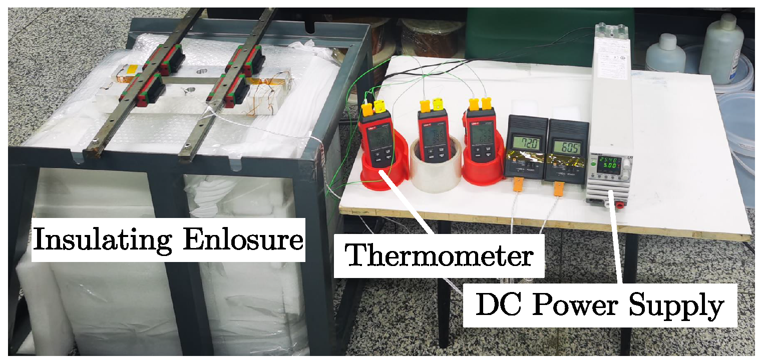
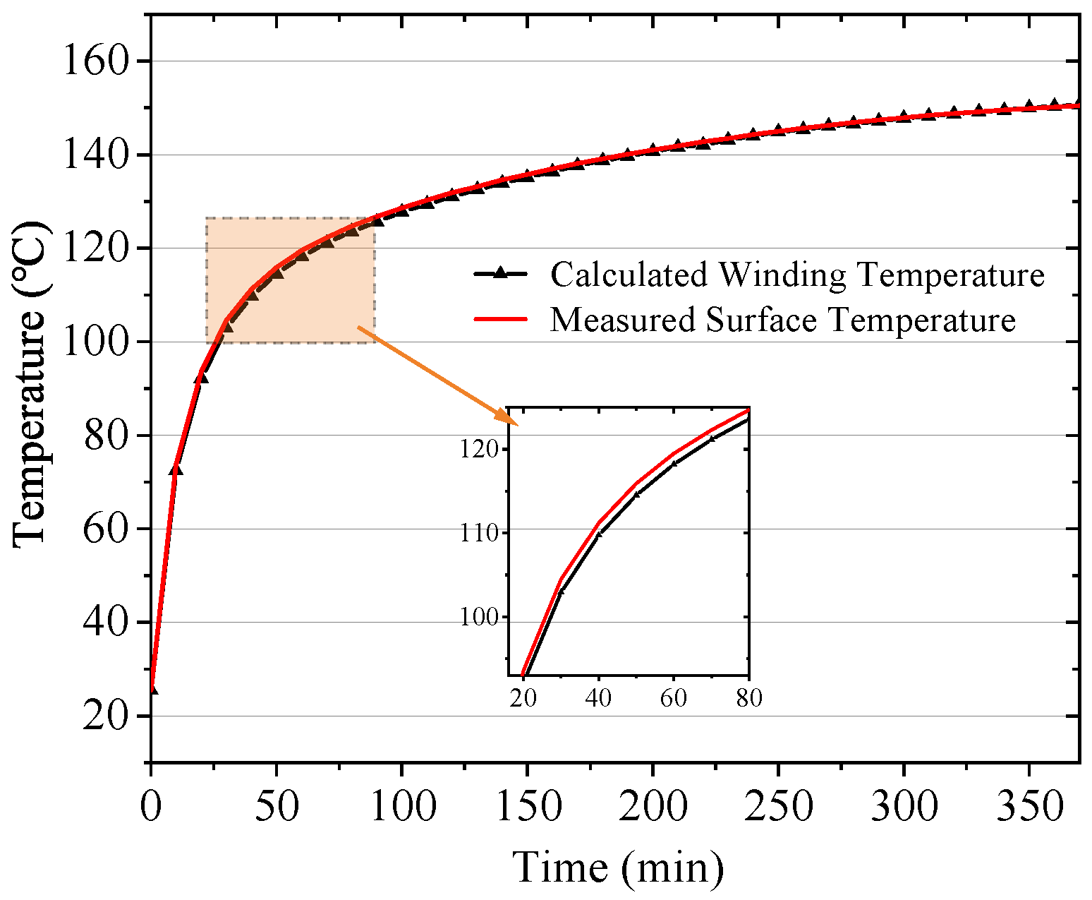
5.2. The Temperature Test of the LAG-VCM Prototype

An experimental platform was constructed to assess whether the proposed heat pipe-assisted cooling strategy can effectively mitigate thermal buildup under vacuum-like conditions. As shown in Figure 22, a pair of miniature heat pipes (each 8 mm × 3.25 mm ) was affixed at each attachment location on the coil stator using Dow 4485L thermally conductive adhesive. By spanning the high-temperature coil region leading toward the motor’s base, these heat pipes establish a high-conductivity heat path to supplement conduction through the comparatively insulating epoxy resin.
To approximate a vacuum environment, where neither forced convection nor air cooling is available, a low-conductivity foam enclosure was used to house the entire VCM during testing. This enclosure significantly impedes convective and conductive heat transfer to the ambient environment. Although not a literal vacuum chamber, it ensures that radiative cooling and conduction through internal structures dominate the heat-dissipation mechanism, closely mirroring thermal behavior in a vacuum.
The resultant test platform is depicted in Figure 23. A KIKUSUI PWR401ML DC (manufactured by Kikusui Electronics Corporation, Yokohama, Japan) power supply provided a constant 5 A current to the coil, while a UNI-T UT320D digital thermometer (manufactured by Uni-Trend Technology Co., Ltd., Dongguan, China) continuously recorded the temperature of the epoxy-encapsulated coil surface. Since the surface epoxy region is typically one of the hottest points accessible from outside, it offers a practical location for in situ temperature measurement. Meanwhile, the coil’s winding temperature was inferred by monitoring the real-time voltage drop across the coil.
By applying the linear temperature coefficient relation
T = T 0 + U I R 0 α R 0 = T 0 + U I R 0 · 1 α 1 α
one can translate the measured U / I into a winding temperature T, given a known reference resistance R 0 at the baseline temperature T 0 and the copper’s temperature coefficient α .
Figure 24 shows how the coil temperature, as derived from both direct surface measurements and voltage-based calculations, initially rose sharply within the first hour and then transitioned into a slower climb before stabilizing at around 150 °C. This steady-state temperature aligns well with the finite element thermal predictions, indicating that the heat pipes successfully enhance conduction away from the coil in a low-convection environment. In turn, the insulation foam prevents outside airflow from masking any shortcomings in the heat pipe design, ensuring that the observed cooling performance is genuinely attributable to the heat pipes themselves rather than ambient convection.
These experimental findings confirm that the implemented heat pipe cooling arrangement provides a significant thermal pathway sufficient to keep the winding temperature well under the Class H limit of 180 °C. Even in this foam-insulated (and thus convection-deprived) environment, the coil settled at approximately 150 °C, closely matching the numerical thermal analysis. Consequently, this setup demonstrates the viability of using lightweight heat pipes in vacuum or near-vacuum applications where conventional forced air or fluid cooling is impractical, ensuring safe coil operating temperatures while preserving the motor’s large air gap and required stroke.

6. Conclusions

A comprehensive investigation into the design and implementation of an LAG-VCM for vacuum-based vibration isolation has been presented. The use of the equivalent magnetic charge method and the image method accurately captured the magnetostatic field distribution in the presence of a large air gap, while finite element optimization minimized the thrust ripple and addressed the leakage flux. Experimental tests verified that the motor achieved the targeted thrust range and maintained satisfactory linearity across its travel span. Additionally, a heat pipe-based cooling arrangement effectively reduced the coil temperature under continuous loading in vacuum-like conditions, demonstrating a viable solution for environments where conventional convective cooling is unavailable. These results highlight the potential of the optimized LAG-VCM in applications requiring a compact size, low disturbance, and reliable high-force output. Future work may extend the thermal design to higher power levels and investigate integrated control schemes for enhanced dynamic performance, further solidifying the role of large-air-gap actuators in precise spaceborne or vacuum-oriented systems.

Author Contributions

Conceptualization, J.M. and H.Z.; methodology, H.Z.; software, J.M.; validation, J.M. and H.Z.; formal analysis, H.Z.; investigation, J.M.; resources, H.Z.; data curation, H.Z.; writing—original draft preparation, J.M.; writing—review and editing, H.Z.; visualization, J.M.; supervision, H.Z.; project administration, H.Z.; funding acquisition, H.Z. All authors have read and agreed to the published version of the manuscript.

Funding

This work was supported by the National Natural Science Foundation of China under Grant 52377044 and the Natural Science Foundation of Heilongjiang Province of China under Grant YQ2024E025.

Data Availability Statement

Data are contained within the article.

Conflicts of Interest

The authors declare no conflicts of interest.

Abbreviations

The following abbreviations are used in this manuscript:
LAG-VCMLarge-air-gap voice coil motor
FEAFinite element analysis

References

  1. Ling, Y.; Wu, S.; Gu, J.; Lai, H. A novel ring spring vibration isolator for metro superstructure. Appl. Sci. 2021, 11, 8422. [Google Scholar] [CrossRef]
  2. Araki, Y.; Asai, T.; Kimura, K.; Maezawa, K.; Masui, T. Nonlinear vibration isolator with adjustable restoring force. J. Sound Vib. 2013, 332, 6063–6077. [Google Scholar] [CrossRef]
  3. Voigtländer, B.; Coenen, P.; Cherepanov, V.; Borgens, P.; Duden, T.; Tautz, F.S. Low vibration laboratory with a single-stage vibration isolation for microscopy applications. Rev. Sci. Instrum. 2017, 88, 023703. [Google Scholar] [CrossRef] [PubMed]
  4. Qu, D.; Liu, X.; Liu, G.; Bai, Y.; He, T. Analysis of vibration isolation performance of parallel air spring system for precision equipment transportation. Meas. Control 2019, 52, 291–302. [Google Scholar] [CrossRef]
  5. Law, M.; Wabner, M.; Colditz, A.; Kolouch, M.; Noack, S.; Ihlenfeldt, S. Active vibration isolation of machine tools using an electro-hydraulic actuator. CIRP J. Manuf. Sci. Technol. 2015, 10, 36–48. [Google Scholar] [CrossRef]
  6. Henderson, J.-P.; Plummer, A.; Johnston, N. An electro-hydrostatic actuator for hybrid active-passive vibration isolation. Int. J. Hydromechatronics 2018, 1, 47–71. [Google Scholar] [CrossRef]
  7. Xu, D.; Yu, Q.; Zhou, J.; Bishop, S.R. Theoretical and experimental analyses of a nonlinear magnetic vibration isolator with quasi-zero-stiffness characteristic. J. Sound Vib. 2013, 332, 3377–3389. [Google Scholar] [CrossRef]
  8. Yan, B.; Yu, N.; Wang, Z.; Wu, C.; Wang, S.; Zhang, W. Lever-type quasi-zero stiffness vibration isolator with magnetic spring. J. Sound Vib. 2022, 527, 116865. [Google Scholar] [CrossRef]
  9. Ma, Z.; Zhou, R.; Yang, Q.; Lee, H.P.; Chai, K. A semi-active electromagnetic quasi-zero-stiffness vibration isolator. Int. J. Mech. Sci. 2023, 252, 108357. [Google Scholar] [CrossRef]
  10. Chen, X.; Zhao, J.; Jing, Y.; Cao, X.; Yuan, S.; Luo, J.; Pu, H. A novel permanent magnet vibration isolator with wide stiffness range and high bearing capacity. Mechatronics 2024, 98, 103119. [Google Scholar] [CrossRef]
  11. Zhao, Y.; Cui, J.; Bian, X.; Zou, L.; Liang, S.; Wang, L. Study on Performance of an air spring isolator for large-scale precision optical micro-vibration isolation. In Proceedings of the 3rd International Conference on Information Technologies and Electrical Engineering, Changde, China, 3–5 December 2020; pp. 173–178. [Google Scholar]
  12. Zhang, H.; Lou, Y.; Zhou, L.; Kou, Z.; Mu, J. Modeling and Optimization of a Large-Load Magnetic Levitation Gravity Compensator. IEEE Trans. Ind. Electron. 2022, 70, 5055–5064. [Google Scholar] [CrossRef]
  13. Kim, J.-Y.; Ahn, D. Analysis of high force voice coil motors for magnetic levitation. Actuators 2020, 9, 133. [Google Scholar] [CrossRef]
  14. Lee, K.-M. Design and analysis of a vertically moving voice coil motor with gravity compensation for semiconductor equipment. Sens. Actuators A Phys. 2022, 344, 113735. [Google Scholar] [CrossRef]
  15. Lin, Y.-H.; Liu, C.-S.; Yeh, C.-N. Design and Simulation of Novel 3-DOF Spherical Voice Coil Motor. Actuators 2021, 10, 155. [Google Scholar] [CrossRef]
  16. Zhang, Z.; Luo, M.; Zhou, H.; Duan, J.-A. Design and analysis of a novel two-degree-of-freedom voice coil motor. IEEE/ASME Trans. Mechatronics 2019, 24, 2908–2918. [Google Scholar] [CrossRef]
  17. Zhang, H.; Kou, B.; Ge, Q.; Liu, Y. Design and analysis of a high thrust linear voice coil motor using for the stiffness test of linear motor servo system. IEEE Trans. Magn. 2021, 58, 1–5. [Google Scholar] [CrossRef]
  18. Chi, F.; Wu, L.; Yang, X. Optimum design of voice coil motor using for nano-stage in lithographic equipment. In Proceedings of the 11th World Congress on Intelligent Control and Automation, Shenyang, China, 29 June–4 July 2014; pp. 2540–2543. [Google Scholar]
  19. Zhang, Z.-J.; Zhou, H.-B.; Duan, J.-A.; Kou, B.-Q. Design and analysis of two-degree-of-freedom voice coil motors for linear-rotary motion. In Proceedings of the 19th International Conference on Electrical Machines and Systems (ICEMS), Chiba, Japan, 13–16 November 2016; pp. 1–6. [Google Scholar]
  20. Chen, Y.-D.; Fuh, C.-C.; Tung, P.-C. Application of voice coil motors in active dynamic vibration absorbers. IEEE Trans. Magn. 2005, 41, 1149–1154. [Google Scholar] [CrossRef]
  21. Li, L.; Pan, D.; Liu, J.; Wang, M.; Guo, Q.; Peng, E. Analysis and modeling of air-core monopole linear motor for nanopositioning system. IEEE Trans. Magn. 2013, 49, 3977–3980. [Google Scholar] [CrossRef]
  22. Mu, J.; Zhang, H. Design and Optimization of Large Air-Gap Voice Coil Motor for Application in Magnetic Levitation Platform. In Proceedings of the 11th Chinese Symposium on Magnetic Levitation Technology and Vibration Control (CSMLVC11), Changsha, China, 4–7 August 2023; p. 231. [Google Scholar]
  23. Ravaud, R.; Lemarquand, G.; Lemarquand, V.; Depollier, C. Analytical calculation of the magnetic field created by permanent-magnet rings. IEEE Trans. Magn. 2008, 44, 1982–1989. [Google Scholar] [CrossRef]
  24. Ravaud, R.; Lemarquand, G.; Lemarquand, V.; Depollier, C. Permanent magnet couplings: Field and torque three-dimensional expressions based on the Coulombian model. IEEE Trans. Magn. 2009, 45, 1950–1958. [Google Scholar] [CrossRef]
  25. Rakotoarison, H.L.; Yonnet, J.-P.; Delinchant, B. Using Coulombian approach for modeling scalar potential and magnetic field of a permanent magnet with radial polarization. IEEE Trans. Magn. 2007, 43, 1261–1264. [Google Scholar] [CrossRef]
  26. Lee, S.-H.; Park, S.-B.; Kwon, S.-O.; Lee, J.-Y.; Lee, J.-J.; Hong, J.-P.; Hur, J. Characteristic analysis of the slotless axial-flux type brushless DC motors using image method. IEEE Trans. Magn. 2006, 42, 1327–1330. [Google Scholar]
  27. Zhang, H.; Kou, B.; Zhang, H.; Jin, Y. A Three-Degree-of-Freedom Short-Stroke Lorentz-Force-Driven Planar Motor Using a Halbach Permanent-Magnet Array With Unequal Thickness. IEEE Trans. Ind. Electron. 2015, 62, 3640–3650. [Google Scholar] [CrossRef]
Figure 1. The configuration of the vibration isolation platform for the CSST experiment. (a) A model of the platform and an illustration of the compensator and voice coil motor. (b) A simplified diagram of the platform.
Actuators 14 00301 g001
Figure 2. Structure of voice coil motor, where red and blue arrows denote the magnetization directions, and the pink arrow denotes the coil current direction.
Actuators 14 00301 g002
Figure 3. Equivalent magnetic charge model of vertically magnetized permanent magnet P ( x , y , z ) is the field point in free space, Q ( x 0 , y 0 , z 0 ) denotes a surface source point on the magnet face, d s is the differential surface area, r is the distance from Q to P, and θ is the angle between r and the z axis.
Actuators 14 00301 g003
Figure 4. Schematic of the image method for PM located between two parallel ferromagnetic boundaries. The black regions are the real magnets; the orange regions are the first-order fictitious image magnets; the blue regions are the second-order image magnets; H is the separation between the ferromagnetic plates.
Actuators 14 00301 g004
Figure 5. The 2D FEA model of voice coil motor.
Actuators 14 00301 g005
Figure 6. Voice coil motor thrust–displacement diagram.
Actuators 14 00301 g006
Figure 7. VCM air-gap magnetic flux density distribution.
Actuators 14 00301 g007
Figure 8. Magnetic field of voice coil motor. (a) Diagram of magnetic field lines. (b) Diagram of magnetic flux density distribution.
Actuators 14 00301 g008
Figure 9. Diagrams of thrust and thrust ripple vs. height of PM. (a) Diagram of thrust–height of PM. (b) Diagram of thrust ripple–height of PM.
Actuators 14 00301 g009
Figure 10. Diagrams of thrust and thrust ripple vs. height of yoke. (a) Diagram of thrust–height of yoke. (b) Diagram of thrust ripple–height of yoke.
Actuators 14 00301 g010
Figure 11. Diagrams of thrust and thrust ripple vs. width of PM. (a) Diagram of thrust–width of PM. (b) Diagram of thrust ripple–width of PM.
Actuators 14 00301 g011
Figure 12. Diagrams of thrust and thrust ripple vs. height of coil. (a) Diagram of thrust–height of coil. (b) Diagram of thrust ripple–height of coil.
Actuators 14 00301 g012
Figure 13. A comparison of the air-gap flux density obtained using the analytical method and 3D finite element method at distances of 1 mm, 2 mm, 3 mm, 4 mm, 5 mm, and 11.5 mm from the magnet surface.
Actuators 14 00301 g013
Figure 14. Comparison of thrust versus displacement at a coil current of 5 A computed by analytical model (green), 3D FEA (orange), and 2D FEA (blue); the maximum difference between the analytical and 3D FEA results is 1.1 N (approximately 0.4%).
Actuators 14 00301 g014
Figure 15. Baseline finite element thermal simulation of the VCM with no additional cooling measures.
Actuators 14 00301 g015
Figure 16. A 3D model illustrating the VCM with heat pipes attached to the epoxy potting and the upper portion of the aluminum frame.
Actuators 14 00301 g016
Figure 17. Finite element thermal simulation after adding heat pipes, showing the coil temperature reduced to approximately 140 °C.
Actuators 14 00301 g017
Figure 18. Prototype of large-air-gap voice coil motor.
Actuators 14 00301 g018
Figure 19. Experimental platform for voice coil motor.
Actuators 14 00301 g019
Figure 20. Comparison of thrust versus current at no displacement; all four methods show excellent linearity, with test values slightly lower and 2D FEA values slightly higher than analytical and 3D FEA results.
Actuators 14 00301 g020
Figure 21. Thrust–displacement curves at currents from 1.5 A to 5 A, illustrating near-linear thrust increase with current and a consistent 6% ripple.
Actuators 14 00301 g021
Figure 22. Prototype stator with heat pipes attached using thermally conductive adhesive.
Actuators 14 00301 g022
Figure 23. Insulated temperature-rise test platform simulating vacuum-like conditions.
Actuators 14 00301 g023
Figure 24. Measured surface temperature and voltage-inferred winding temperature versus time.
Actuators 14 00301 g024
Table 1. Voice coil motor design requirements.
Design RequirementShort DesignationValueUnits
Continuous Thrust F N 250N
Peak Thrust F MAX 300N
Rated Current I N 5A
Single-Side Air Gap δ 4mm
Maximum Dimensions-160 × 100 × 320mm
Table 2. Dimensions and material properties of LAG-VCM.
SymbolQuantityValueUnits
B r Remanence1.385T
H c Coercivity1073kA/m
μ r Relative permeability1.027
w m PM width36mm
h m PM height8mm
τ Polar pitch40mm
w c Coil width24mm
h c Coil height15mm
h y Yoke height11mm
NCoil turns264
δ Electromagnetic air gap4mm
Disclaimer/Publisher’s Note: The statements, opinions and data contained in all publications are solely those of the individual author(s) and contributor(s) and not of MDPI and/or the editor(s). MDPI and/or the editor(s) disclaim responsibility for any injury to people or property resulting from any ideas, methods, instructions or products referred to in the content.

