Article

The Design of a Turning Tool Based on a Self-Sensing Giant Magnetostrictive Actuator

by
Dongjian Xie
1,2,
Qibo Wu
1,
Yahui Zhang
1,
Yikun Yang
1,
Bintang Yang
1,* and
Cheng Zhang
3,*
1
State Key Laboratory of Mechanical System and Vibration, School of Mechanical Engineering, Shanghai Jiao Tong University, Shanghai 200240, China
2
Aerospace System Engineering Shanghai, Shanghai 201109, China
3
Facility Design and Instrumentation Institute, China Aerodynamics Research and Development Center, Mianyang 621000, China
*
Authors to whom correspondence should be addressed.
Actuators 2025, 14(6), 302; https://doi.org/10.3390/act14060302
Submission received: 9 May 2025 / Revised: 14 June 2025 / Accepted: 18 June 2025 / Published: 19 June 2025
(This article belongs to the Special Issue Recent Developments in Precision Actuation Technologies)

Abstract

:
Smart tools are limited by actuation–sensing integration and structural redundancy, making it difficult to achieve compactness, ultra-precision feed, and immediate feedback. This paper proposes a self-sensing giant magnetostrictive actuator-based turning tool (SSGMT), which enables simultaneous actuation and output sensing without external sensors. A multi-objective optimization model is first established to determine the key design parameters of the SSGMT to improve magnetic transfer efficiency, system compactness, and sensing signal quality. Then, a dynamic hysteresis model with a Hammerstein structure is developed to capture its nonlinear characteristics. To ensure accurate positioning and a robust response, a hybrid control strategy combining feedforward compensation and adaptive feedback is implemented. The SSGMT is experimentally validated through a series of tests including self-sensing displacement accuracy and trajectory tracking under various frequencies and temperatures. The prototype achieves nanometer-level resolution, stable output, and precise tracking across different operating conditions. These results confirm the feasibility and effectiveness of integrating actuation and sensing in one structure, providing a promising solution for the application of smart turning tools.

1. Introduction

Machining is widely used in the final molding of metal or non-metal parts in industry. With the continuous improvement in the complexity and geometric accuracy of design products, the application of new materials, and the shortening of product life cycle, the level of intelligence and automation of manufacturing equipment is facing major challenges [1]. With the development of technology, new mechatronics integrated in intelligent manufacturing equipment have gradually developed to meet the needs of the times. Compared with ordinary manufacturing equipment, intelligent manufacturing equipment is different in that it integrates different types of actuators and sensors to improve the equipment’s sensitivity to and control of the machining process, as well as ensuring machining accuracy and machining system robustness [1,2,3].
As the appendage of manufacturing equipment, tools are also being developed to achieve precision and intelligence in cutting processing. Based on traditional tools, intelligent tools are integrated with precision drive and sensing technologies [4,5]. To ensure cutting functions, intelligent tools can achieve real-time adjustment of machining parameters [6,7], online monitoring of their own working conditions [8], and communication and interaction with numerical control systems [5].
Limited by the narrow installation space and specific design performance requirements, intelligent tools have specific requirements for the appearance of the driver geometry, output scale, operating frequency, and output power. Electromagnetic actuators are widely used in the field of intelligent tools, such as the voice coil motor driven by Lorentz force [9] and the micro solenoid actuator driven by Maxwell force [10]. In the process of miniaturization, the physical properties of the electromagnetic drive and the key structural guiding elements are prone to adverse scaling effects, and as such, the output force will be proportional to the fourth square of the structural size [11]. Drivers based on smart materials are widely used in the field of smart tools because of their superior performance in response speed, output energy, robustness, and easy control. Currently, piezoelectric materials (PZTs) [11], magnetorheological liquids (MRFs) [12], shape memory alloys (SMAs) [13], and giant magnetostrictive materials (GMMs) [14] are widely used.
The typical application of the integration of drive and sensing functions in smart tools is to use the sensor with the driver to assist the cutting tool for machining, or to install the cutting tool directly on the output end of the driver for machining. A representative of this class of applications is the fast tool servo (FST) system. FST systems play an important role in precision turning of micro-features or free-form surfaces of diamond tools, with common structures including piezoelectric [15] or voice coil drivers [16], flexure hinges, and position feedback sensors. In addition, in order to adapt to more complex design requirements and machining requirements of different drive frequencies, normal stress electromagnetic drives are also gradually applied to FST systems. Huang et al. [17] proposed a normal stress electromagnetic-driven FST system, in which flexible hinges were used to amplify the output displacement of the electromagnetic driver, and capacitive displacement sensors were installed inside the FST system to detect the output displacement. By modifying the conventional manufacturing device, the intelligent tool can further expand the process performance of the device on the basis of retaining the original processing capacity. Yoshioka et al. [18] integrated a giant magnetostrictive actuator (GMA) inside a milling machine spindle to process complex surfaces and fine patterns alongside conventional milling. However, in current smart tools, the drive and external sensors function as separate components, resulting in a bulky structure and complex installation, along with calibration errors and inconsistent responses due to diverse sensing mechanisms and vibration coupling. This study aims to fundamentally address issues of structural redundancy, matching difficulties, and vibration interference by integrating actuation and self-sensing capabilities into a single device, thereby enhancing the precision machining performance of smart tools.
To address the above challenges, this paper presents a self-sensing giant magnetostrictive actuator-based turning tool (SSGMT), in which both actuation and displacement sensing are realized within a unified structure. A coupled multi-physical model is developed to characterize the magneto–mechanical–thermal behavior of the actuator, and a Hammerstein-like dynamic hysteresis model is introduced to capture its nonlinear input–output characteristics. Based on this model, a constrained multi-objective optimization framework is established, balancing energy efficiency, magnetic field strength, mechanical stiffness, and system mass. The key structural parameters are optimized accordingly, and a prototype of the SSGMT is fabricated for subsequent validation. In addition, a hybrid control scheme combining inverse feedforward compensation and adaptive feedback is designed to suppress nonlinear hysteresis and enhance trajectory tracking accuracy.
The remainder of this paper is organized as follows. Section 2 introduces the working principle and mechanical structure of the SSGMT. Section 3 presents the multi-objective optimization model for key structural parameters and its solution. Section 4 describes the design of the nonlinear dynamic model and the composite control strategy. Section 5 reports the experimental validation results including displacement resolution, self-sensing accuracy, and tracking performance under various thermal and dynamic conditions. Finally, Section 6 summarizes the main conclusions and discusses future prospects.

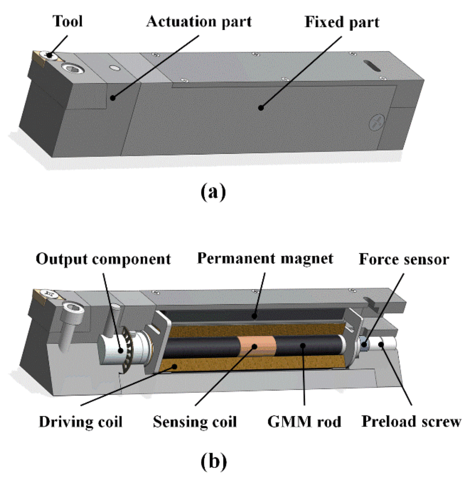
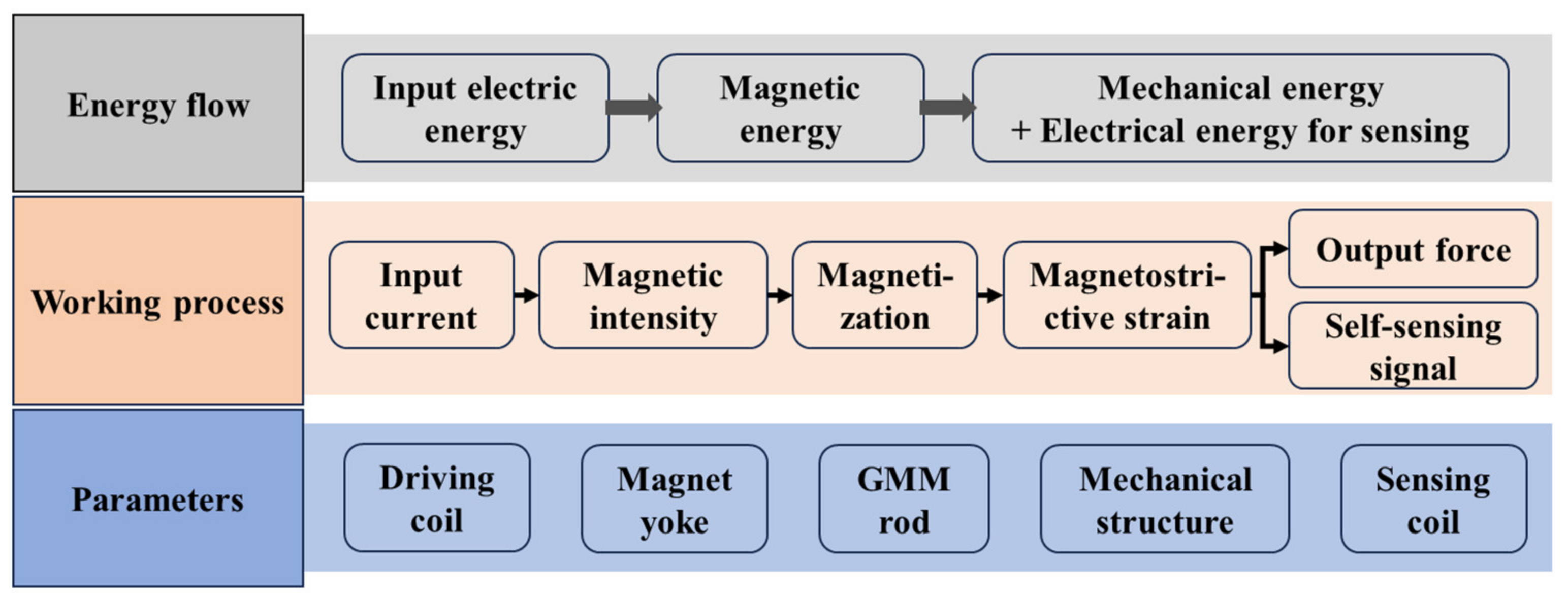
2. Working Principle and Structure Scheme

The self-sensing giant magnetostrictive actuator (SSGMA) proposed in this paper has the ability to achieve linear feed with micro- and nano-level precision. Due to the magnetic–mechanic–thermal coupling characteristics of giant magnetostrictive materials, the SSGMA can detect its own output displacement and force during execution and sense the change in working environment temperature [19,20]. Based on detailed research on the characteristics of the SSGMA, the multi-physical self-sensing actuator is presented. In order to apply the SSGMA mechanism to practical engineering, this section proposes and designs a self-sensing giant magnetostrictive actuator-based turning tool (SSGMT) based on the SSGMA. Figure 1 shows the mechanical structure diagram of the designed SSGMT. The external structure of the SSGMT is shown in Figure 1a, which includes three parts: fixed parts, executive parts and machining tools. Among them, the fixed parts are responsible for the connection with the lathe chuck, and the executive parts are connected through the pin; the processing tool is fixed on the executive parts by a special screw, and the specific model of the processing tool needs to be selected according to the actual processing needs.
The internal structure of the fixed component is shown in Figure 1b. The internal structure of the giant magnetostrictive self-sensing driver is the same as that of the giant magnetostrictive rod. The sensor coil is installed in the middle of the giant magnetostrictive rod, and the two are completely wrapped inside the drive coil. A magnetic yoke is placed around the driving coil to form a complete closed magnetic circuit with a permanent magnet that provides a biased magnetic field, so that the magnetic field evenly passes through the giant magnetostrictive rod. At the end of the fixed part, the preload nut fixes the force sensor to the rear end of the giant magnetostrictive rod. By adjusting the preload nut, the prestress applied to the giant magnetostrictive rod can be adjusted. The force sensor is used to detect the magnitude of the prestress and at the same time to monitor the load borne during SSGMT operation in order to calibrate the self-sensing signal. The front end of the giant magnetostrictive rod is equipped with an output component, which is connected with the actuator through a pin, and a guide ring is placed around the output component to reduce non-axial movement during execution. In the actual working process, the external magnetic field of the giant magnetostrictive rod is provided by the permanent magnet and the drive coil, and the sensing signal is extracted from the sensor coil in real time.

3. Optimization of Structural Parameters

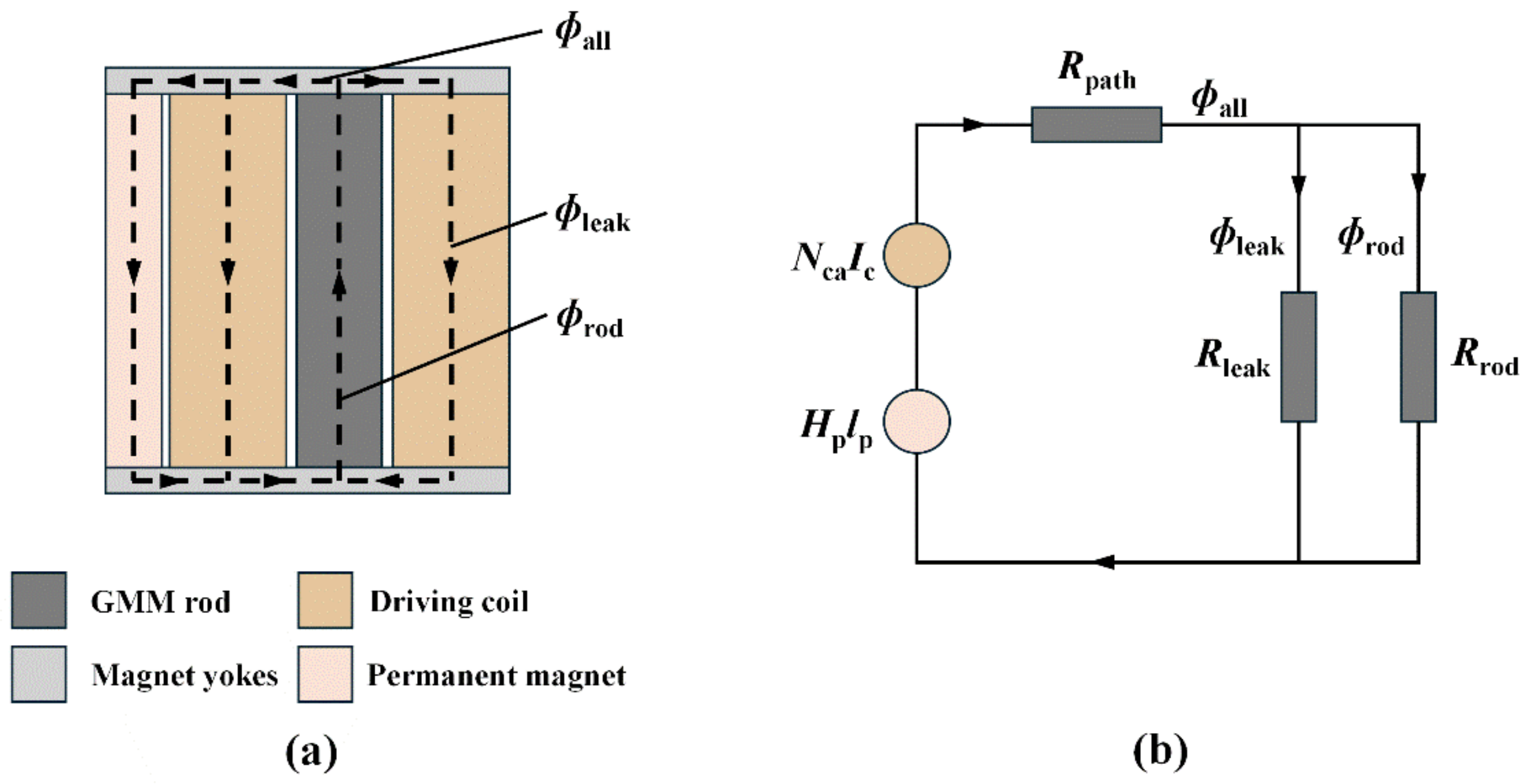
3.1. Parameter Analysis

For the actual engineering application scenarios of lathe cutting, the optimization design principles for the SSGMT should include the following: (1) reducing energy consumption, mainly the loss of magnetic energy, to ensure that the output of the GMM rod provides a uniform and stable driving magnetic field; (2) improving the quality factor of the self-sensing signal to ensure that it can effectively perceive its own state while stabilizing the output; (3) on the premise of ensuring the strength and stiffness of the mechanical system, reducing the size and quality of the mechanical structure, on the one hand, to adapt to the use of the actual machine tool space and, on the other hand, to avoid bringing too much additional redundancy to the machine tool and affecting its effective function. This section will optimize the design of key components under the premise of ensuring SSGMT output capability.
For the SSGMT, the analysis of the whole drive system from the perspective of energy flow includes three key links, namely, the electromagnetic conversion link, magnetic energy transfer link, and electromechanical output link, as shown in Figure 2. In the electromagnetic conversion process, the electric energy input to the system is converted into magnetic energy through the drive coil, so the parameters of the drive coil directly affect the efficiency of electromagnetic conversion. The energy lost in this process is mainly due to coil magnetic leakage loss and heating loss. In the magnetic energy transfer link, the magnetic energy is transferred in the magnetic circuit to magnetize the GMM rod, so the eddy current loss caused by the magnetic yoke in this link is related. Finally, the magnetic energy is converted into mechanical energy, and the displacement and force output by the GMM rod are transferred to the outside of the system through the mechanical structure to carry out work. Therefore, the energy lost in this process is related to the magneto conversion efficiency of the GMM rod, and the size of the GMM rod and the equivalent stiffness of the associated components will also affect the output performance of the SSGMT. In addition, some energy is converted into inductive electrical signals through the sensing coil, which directly affects the signal quality of the self-sensing signal; so, it is also necessary to optimize the sensor coil design.
In order to build an optimal design model, theoretical analysis and parameter modeling are carried out for the key links involved in the above SSGMT working process:
  • Drive coil energy loss analysis
In the electromagnetic conversion process of the SSGMT, the drive coil mainly converts external input electric energy into magnetic energy. The system’s magnetic circuit which forms part of the drive process is shown in Figure 3a. The total magnetic flux in the system a l l is generated by the joint action of the drive coil and permanent magnet and transmitted through the magnetic circuit formed by the magnetic yoke; part of the magnetic flux r o d passes through the GMM rod. The GMM rod is magnetized and deformed, and part of   l e a k is lost as the magnetic leakage flux of the driving coil. In addition, there is a certain degree of magnetic leakage in the air, which is ignored in the analysis due to its small magnitude. According to the above process, the equivalent magnetic circuit model is established, as shown in Figure 3b. The number of turns and the input current of the drive coil are N c a and   I c , the coercive magnetic field and length of the permanent magnet are H p and   I p , and the magnetic leakage impedances of the drive coil, GMM rod, and magnetic circuit are R l e a k , R r o d , and   R p a t h , respectively. In order to increase the magnetic flux through the GMM rod, the value of R l e a k should be increased as much as possible, which also means that the magnetic leakage inductance of the drive coil should be reduced as much as possible.
The driving coil is in the form of a conventional solenoid coil. The inner diameter of the coil is r c a 1 , the outer diameter is r c a 2 , the length is l c a , and the radius of the enamelled wire composed of the driving coil is d c a . The GMM rod is placed inside the drive coil with a radius of r m and a length of l m . The number of turns N c a of the drive coil can be calculated directly from the size parameter of the coil, which is specifically expressed as follows:
N c a = l c a r c a 2 r c a 1 η c 1 η c 2 d c a 2
η c 1 is the axial winding coefficient of the solenoid coil, which is usually 1.05. η c 2 is the radial winding coefficient of the solenoid coil, usually 1.15. When the input current is I c , the input magnetic field H c provided by the N c a turn drive coil can be expressed as follows [21]:
H c = G c a N c a I c π α c a + 1 l c a r c a 1 α c a 1
where G c a is the geometric shape parameter of the drive coil, which can be expressed as follows:
G c a = 1 5 2 π β c a α c a 2 1 ln α c a + α c a 2 + β c a 2 1 + 1 + β c a 2
In the above formula, α c a = r c a 2 / r c a 1 and β c a = l c a / 2 r c a 1 ; according to the Biot–Savart law, the magnetic leakage inductance L c a l e a k of the drive coil with the above parameters can be calculated as follows:
L c a l e a k = μ 0 π 2 G c a 2 N c a 2 r m γ c a 2 1 α c a + 1 γ c a α c a 1 + r c a 1 α c a + 1 α c a + 3 6
where γ c a = r c a 1 / r m . For the design in this section, the inner diameter of the drive coil r c a 1 is approximately   r m . Therefore, through optimal design of the structure parameters of the drive coil, the output magnetic field strength is stronger and the magnetic leakage loss is smaller under the same input current. According to the magnetic energy theory [22], the loss of the drive coil due to magnetic leakage per unit time can be calculated as follows:
W c l = 1 2 I c 2 L c a l e a k
In addition to magnetic leakage loss, coil loss due to heat also has a huge impact. In actual work, the current input to the SSGMT drive coil is composed of two parts: one is the low-frequency and high-amplitude current used to drive the GMM rod, and the other is the high-frequency and low-amplitude current used for sensing excitation. Therefore, considering the heat loss of the coil, the coil impedance should be considered. Among them, the static resistance R c d c caused by the DC current and the AC resistance R c a c caused by the AC current due to the “skin effect” are included. According to the literature [23], by ignoring the inductive reactance of the coil with less influence, the heating loss of the drive coil per unit time can be expressed as follows:
W c h = I c 2 R c d c 2 + R c a c 2
The static resistance R c d c is related to the structural parameters of the drive coil and can be expressed as follows:
R c d c = N c a 2 ρ c w π α c a + 1 λ c l c a α c a 1
ρ c w is the winding resistivity of the copper coil, generally 1.72 × 10 8 Ω m ; R c d c is the form factor of the copper coil, and π/4 is taken when the copper section is circular. The AC resistance R c a c is related to the current frequency fc of the input drive coil and can be calculated as follows:
R c a c = l c a w π μ 0 ρ c w f c π d c a
where l c a w is the total length of the winding of the copper coil, which can be approximately expressed as follows:
l c a w = N c a π r c a 1 + r c a 2
Based on the above analysis, the energy loss caused by the drive coil in the electromagnetic conversion process can be expressed as follows:
W c a = W c l + W c h
Therefore, on the premise of ensuring the output performance of the SSGMT, the coil parameters are optimized to reduce the value of Formula (10) and reduce the energy loss caused by driving the coil.
II.
Drive magnetic field strength analysis
As shown in Figure 3b, after optimizing the magnetic flux leakage impedance caused by the coil, the functions of the magnetic yoke and GMM rod are mainly considered in the magnetic circuit, and the magnetic flux leakage caused by air is ignored. Therefore, the magnetic field strength acting on the GMM rod can be calculated as follows [23]:
H r o d = N c a I c + H p l p μ m A m l m μ m A m + 2 μ i r o n t y
where μ m represents the permeability of the GMM rod, μ i r o n represents the permeability of the permeable yoke, and Am and ty represent the cross-sectional area of the GMM rod and the thickness of the permeable yoke, respectively. When the input current is constant, in order to ensure the output performance of the GMM rod, the lower limit of the magnetic field strength should be limited in the optimization design.
III.
Energy loss analysis of the magnetic yoke
In order to ensure that the magnetic field generated by the drive coil and permanent magnet can effectively pass through the GMM rod, a permeable yoke is added to the design to form a complete loop. According to the literature [24], the loss caused by the yoke under the action of the sinusoidal excitation current mainly includes hysteresis loss and eddy current loss. The yoke loss is related to the properties of the material itself, and the determining factor is the overall quality. The eddy current loss caused by the greater mass will increase accordingly; so, the quality of the yoke components should be reduced in the design. The eddy current loss is related to the size of the permeability yoke. In order to ensure that the magnetic field passing through the GMM rod is uniform, an end yoke is arranged at both ends of the GMM rod. Therefore, the eddy current loss W y l caused by the yoke can be approximated as follows [25]:
W y l = π 2 t y 2 B m 2 f c 6 ρ i r o n 1 2 π r c a 2 2 + 2 r c a 2 2 + w p h p t y
where ρ i r o n is the resistivity of the material composed of the magnetic yoke, the material is permalloy, and the resistivity ρ i r o n = 0.1   μ Ω · m ; f c represents the current frequency, t y represents the thickness of the permeable yoke, and w p and h p represent the width and thickness of the permanent magnet, respectively. B m represents the peak value of magnetic induction intensity inside the permeability yoke, which mainly considers the influence of dynamic current. Specifically, it can be calculated according to the following formula [23]:
B m = N c a I c 1 2 π r c a 2 2 + 2 r c a 2 2 + w p h p l m μ m A m + 2 μ i r o n t y
Based on the above analysis, the optimal design of the structural size of the yoke ensures that the eddy current loss generated by the magnetic conductivity loop is reduced when the input current is constant, and the effective magnetic energy transferred to the GMM rod is increased.
IV.
Analysis of sensor coil design parameters
The sensor coil is directly wound around the GMM rod as a single-layer spiral coil, and its structural parameters include the inner diameter of the coil r c s 1 , the outer diameter r c s 2 , the length l c s , and the radius d c s of the enameled wire forming the coil. As for the analysis of the action of the sensor coil, the induced voltage extracted by the sensor coil as a self-sensing signal is mainly affected by two key factors. One is the cross-sectional area A c s of the changing magnetic flux, which is related to the radius of the GMM rod:
A c s = π r m 2
The other is the number of turns of the sensing coil N c s ; the more turns, the stronger the induction signal, which can be expressed as follows:
N c s = l c s r c s 2 r c s 1 η c 1 η c 2 d c s 2
In order to avoid affecting the layout inside the driver, the sensing coil is provided with only one layer, whose inner diameter r c s 1 is approximately r m . Based on the above analysis, in order to ensure the strength of the self-sensing signal, the design parameters should be optimized to ensure that the number of turns should be reduced as far as possible on the basis of the design index to avoid the influence of the sensing coil on other parts.
V.
Natural frequency analysis of the system
For the SSGMT execution system, its core component, the GMM rod, generally represents the output displacement under the coupling action of the driving magnetic field and the prestressed force exerted by the preloaded disc spring. Therefore, the natural frequency of the execution system can be approximately calculated as follows:
f m = 1 2 π K m m = 1 2 π k m + k d i s c m
where k m and k d i s c are the stiffness of the GMM rod and the prepressed disc spring, respectively, and m is the overall mass of the execution system. The natural frequency of the core components of the execution system directly affects the upper limit of the drive frequency, so this value needs to be as large as possible to meet the design requirements. Since the stiffness of the GMM rod is related to material properties and external input, the key is to design the spring stiffness accordingly, and it is necessary to select a suitable spring model to meet the design size requirements.
VI.
Quality analysis of key components
In order to improve the overall performance of the SSGMT, the overall quality of the system should be reduced as far as possible to ensure the use of its functions. According to the previous analysis, this is conducive to reducing the magnetic loss, but also a smaller volume can boost the overall efficiency of the operation. For the core output components of the tool, the mass of the SSGMT can be approximately considered to be equal to the total mass of the GMM rod, drive coil, sensing coil, and permeability yoke; so, it can be calculated as follows:
m = m m + m c a + m c s + 2 m y
Among them, m m is the mass of the GMM rod, m c a is the mass of the drive coil, m c s is the quality of the sensing coil, and m y represents the quality of the magnetic yoke, which can be calculated as follows:
m m = ρ m π r m 2 l m
m c a = ρ c N c a π 2 d c a 2 r c a 1 + r c a 2 2
m c s = ρ c N c s π 2 d c s 2 r c s 1 + r c s 2 2
m y = ρ y π r c a 2 2 + 4 r c a 2 r c a 2 + t p t y
where ρ m , ρ c , and ρ y represent the densities of the GMM rod, copper coil, and magnetic yoke, respectively. One of the goals of the optimal design should be to reduce the total mass, i.e., the value of Equation (17).

3.2. Multi-Objective Parameter Optimization Model and Results

The SSGMT is designed to achieve precise feed self-sensing drive control, while taking into account the effects of vibration in the actual machining environment of the lathe, to minimize energy consumption, and to improve the quality of the system. Based on the analysis and modeling of the energy conversion and transfer links of the SSGMT, the following constrained multi-objective optimization design model is established:
max H r o d , N c s , f m min W c a , W y l , m s . t .   Constaints   I .   ~   VI .
There are 11 key parameters involved in the model, including the following: the radius r m of the GMM rod and its length l m ; the outer diameter of the drive coil r c a 2 ; the length l c a and the radius of the enamelled wire d c a ; the length of the permanent magnet l p , as well as its width w p and thickness h p ; the length of the sensor coil l c s ; the radius of the enamelled wire d c s ; the thickness of the magnetic yoke t y ; and the stiffness of the disc spring k d i s c .
Considering the actual use of the SSGMT and its size constraints, the selected boundary of the optimization design parameters can be preliminarily determined. In actual use, the SSGMT on one hand can inhibit the spindle vibration of the lathe, while on the one hand, it can carry out linear feed. Here, we set the output stroke of the SSGMT to greater than 100 μm in order to meet the above design requirements, and the GMM rod has a length   l m of 100 mm. According to the literature [23], the length of the drive coil l c a affects the uniformity of the magnetic field passing through the GMM rod, so it should be greater than the length of the GMM rod. The outer diameter of the drive coil r c a 2 is limited by the installation size of the lathe cutter head. According to previous research in [20], in order to measure the self-sensing drive performance of the SSGMT, the magnetic field provided by the drive coil for a short time should reach 100 KA/m, and the bias magnetic field provided by the permanent magnet should exceed 20 KA/m to ensure the working performance of the SSGMT. Taking into account the assembly relationship, after the length of the drive coil lca and the outer diameter r c a 2 are determined, the size of the permanent magnet is also determined. The radius d c a of the drive coil enamelled wire is limited by the maximum drive current, and the radius d c s of the sensing coil enamelled wire is actually limited by the inner diameter of the drive coil. The stiffness disc of the disc spring is related to the assembly size, which can be determined by combining the radius r m of the GMM rod and the outer diameter r c a 2 of the coil. Therefore, the actual parameters that need to be optimized include r m , r c a 2 , l c a , d c a , l c s , and t y .
The solution of (22) is actually to solve a constrained multi-objective optimization problem. Multi-objective optimization refers to the realization of multiple objectives in a specific design scenario, but in the actual application scenario, there are mutual constraints between each objective, so the optimization of all objectives cannot be achieved at the same time. When one of the goals is optimized, it will affect the achievement of the other goals, so it is difficult to find a single optimal solution. Therefore, the purpose of optimal design is to find a compromise among all goals, so that the overall solution achieves the best possible outcome for all goals. At present, there are many related optimization algorithms, including the genetic algorithm, the particle swarm optimization algorithm, the simulated annealing algorithm, and so on [26]. In this section, the particle swarm optimization (PSO) algorithm is used to solve the multi-objective optimization problem. The PSO algorithm is an iterative optimization algorithm inspired by bird predation behavior. The PSO algorithm first generates several random particles and then iteratively searches for the optimal solution. Each particle updates itself by tracking individual extreme values and global extreme values, and finally achieves global target optimization [26]. Based on the PSO algorithm, Matlab optimization toolbox solution is adopted, and the final optimization results are shown in Table 1.

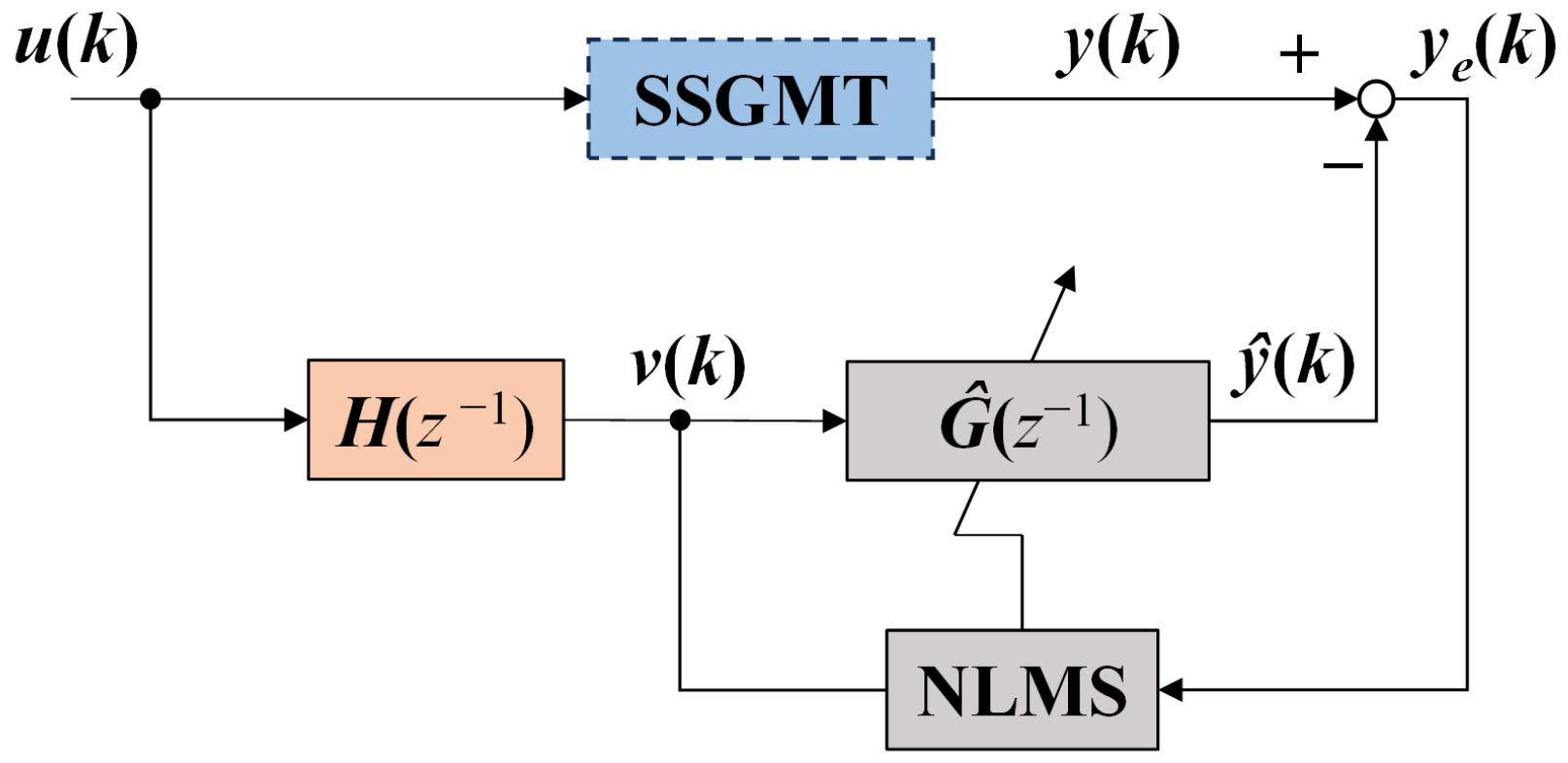
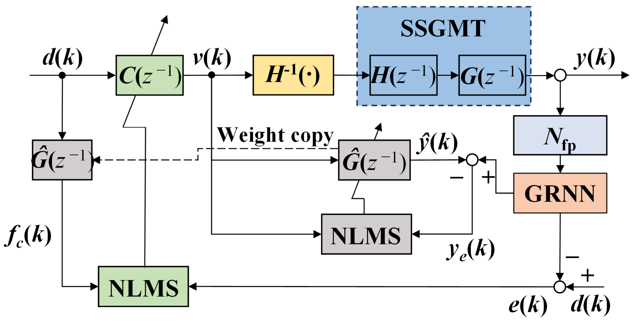
4. Controller Design

To achieve ultra-precision actuation based on smart materials, it is essential to implement appropriate control algorithms. Currently, widely adopted control strategies include feedback control, feedforward control, and hybrid control approaches [27]. The Preisach–Ishlinskii (PI) model characterizes the input–output relationship of hysteresis through the use of play operators and density functions. Due to its capacity for fast and accurate modeling of asymmetric hysteresis behaviors, the PI model has been extensively utilized in the field [28]. In this section, an enhanced PI model based on polynomial operators is employed to describe the nonlinear hysteresis characteristics of GMM. A unilateral play operator is utilized to represent the hysteresis relationship between the input u and output v , and its discrete formulation can be expressed as follows:
H r H u k = h r H u 0 , r H , 0   k = 0 h r H u k , r H , H r H u k   k 1 h r H u , r H , s = max P u r H , min P u , s
where r H = [ r H 0 , r H 1 , , r H m ] T denotes the threshold vector of the unilateral play operators, and k represents a discrete time variable. The hysteresis phenomenon can be characterized using a polynomial operator P ( u ) , which is formulated as follows:
P ( u ) = w p T p ( u )
where p u = u l , u l 1 , , u 0 T   a n d     w p = w p 0 , w p 1 , , w p l T are the polynomial basis vector and the corresponding weight vector, respectively. Accordingly, the improved PI model incorporating the polynomial operator can be expressed as follows:
v ( k ) = w H T H r H [ w p T p ( u ) ] ( k )
where w H = w H 0 , w H 1 , , w H m T denotes the weight vector associated with the unilateral play operators. To compensate for the hysteresis effect, it is necessary to construct an inverse model of hysteresis nonlinearity. The structure of this inverse model is similar to that described in Equations (23) and (24). The final output u ^ of the inverse model based on the polynomial operator-enhanced PI model can be expressed as follows:
u ^ ( k ) = w ^ H T H r ^ H [ w ^ p T p ( v ) ] ( k )
where H r ^ H   denotes the set of unilateral play operators used in the inverse model, and w ^ H and w ^ p represent the corresponding weight vectors for the play operators and the polynomial operators, respectively. It is worth noting that, to reduce computational complexity in practical applications, the parameters of the inverse model are identified directly from experimental data, rather than being obtained through analytical inversion.
To accurately characterize the frequency-dependent hysteresis nonlinearity of GMM, ref. [19] proposes a modeling approach based on the Hammerstein model structure. Building upon this, the present study further employs an online identification strategy to model the dynamic characteristics of the SSGMT with high precision. The structural diagram of the specific model identification algorithm is shown in Figure 4. In this framework, y ( k ) and y ^ k   denote the actual output of the SSGMT and the output of the identified model, respectively, while y e k   represents the modeling error between the actual system output and the model output.
Building upon previous research, a composite control strategy is proposed, which integrates inverse feedforward compensation based on the polynomial-enhanced PI model with a feedforward controller constructed using an adaptive filter. The block diagram of the control algorithm is shown in Figure 5. In this diagram, d k ,     v k ,     y k ,   a n d   e k   represent the desired trajectory, the control current, the actual output of the SSGMT, and the tracking error, respectively. The self-sensing signal is first processed through a lock-in amplifier (denoted as N f p ) and subsequently fed into a generalized regression neural network (GRNN) model to yield the actual output y k of the SSGMT.
In the control algorithm, the hysteresis compensator H 1 ( · ) is cascaded with the plant. As a result, after hysteresis compensation, the estimated model of the compensated system becomes G ^ z 1 = H 1 · · H z 1 · G z 1 = G ( z 1 ) . As illustrated in Figure 5, the tracking error e ( k ) in the z-domain is expressed as follows:
e ( k ) = d ( k ) y ( k ) = 1 C ( z 1 ) G ( z 1 ) d ( k )
When e k = 0 , the actual output of the SSGMT perfectly follows the desired trajectory, indicating zero tracking error. The hysteresis compensator H 1 ( · ) is implemented using the polynomial operator-based PI inverse model identified offline in this section, while the dynamic model G ^ z 1 of the SSGMT is constructed via the online identification method based on the normalized least mean squares (NLMS) algorithm. The specific update algorithm for G ^ z 1 is given as follows:
w g ( n + 1 ) = w g ( n ) + 2 μ g y e ( n ) v ( n ) v ( n ) 2 + τ g
Here, w g ( n ) denotes the weight vector of the estimated system model G ^ z 1 and is defined as w g n = [ w g 0 n , w g 1 n , , w g K 1 n ] T . The parameters   μ g and τ g represent the step-size constant for adjusting the adaptive rate of G ^ z 1   and a small positive constant used to prevent division by zero, respectively. The input signal v n   refers to the compensated version of u ( n ) after processing by H z 1 and is given by v n = [ v n , v n 1 , , v n K + 1 ] T .
The feedforward controller C z 1 adopts a finite impulse response (FIR) filter structure which can be expressed as follows:
C ( z 1 ) = j = 0 K 1 w j c ( k ) z j
where w j c denotes the weight coefficients of the FIR filter that defines C z 1 . These coefficients are updated using the NLMS algorithm. Accordingly, the iterative update formula for the weight vector of C z 1 is given by the following:
w c ( n + 1 ) = w c ( n ) + 2 μ c e ( n ) f c ( n ) f c ( n ) 2 + τ c
Here, w c n = [ w 0 c n , w 1 c n 1 , , w K 1 c n ] T represents the weight vector of the feedforward controller at time step n . The parameters   μ c and τ c are the step-size constant for adjusting the adaptive rate of C z 1 and a small positive regularization constant to avoid division by zero, respectively. The input signal f c n   is generated by filtering the desired trajectory d n through the identified model G ^ z 1 , f c n = [ f c n , f c n 1 , , f c n K + 1 ] T and is defined as follows:
f c ( k ) = j = 0 K 1 d k j w j g ( k )
where k = n , n 1 , , n K + 1 , and the weight vector of G ^ z 1 at time k is denoted as w g k = [ w 0 g k , w 1 g k , , w K 1 g k ] T .

5. Experimental Verification

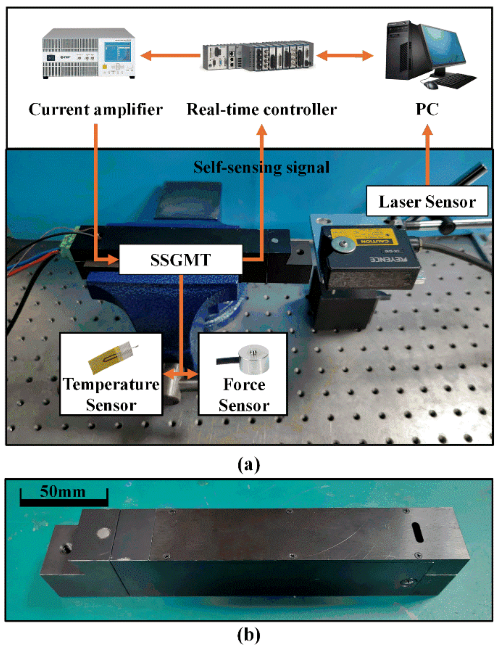
5.1. Experimental Setup

According to the overall scheme proposed in Section 2 and the optimized system structure parameters in Section 3, a prototype of the SSGMT was made, and corresponding basic performance verification experiments were carried out. The device connection diagram of the experimental system is shown in Figure 6a. The SSGMT prototype shell is made of 304 stainless steel with good magnetic insulation and is fixed on a bench vice connected to the optical platform (AVIC Century ZPT-G-Y). Figure 6b shows the appearance of the prototype. The embedded real-time controller CompactRIO-9082 (National Instruments, Austin, USA), on one hand, extracts the SSGMT self-sensing signal collected and processed by the lock-in amplifier MFLI (Zurich Instruments AG, Zurich, Switzerland), and, on the other hand, controls the current input from the power amplifier NF BP4610 (NF Circuit Design Block, Yokohama, Japan) to the SSGMT. The output displacement of the SSGMT prototype is collected by a laser sensor KEYENCE LK-G10 (Keyence Corporation, Osaka, Japan). A type K thermocouple temperature sensor (Cole-Parmer, Vernon Hills, USA) and a force sensor LDC-08 (Shenzhen Ligent Sensor Technology Co., Ltd., Shenzhen, China) are installed inside the SSGMT prototype to detect the load and temperature of the GMM rod in real time.
The core component of the SSGMT is the self-sensing actuator. Unlike conventional actuators, the SSGMT not only executes with precision but also continuously monitors its own output displacement, load force, and operating temperature. Next, the performance of the self-sensing actuator in the previously developed SSGMT will be tested.

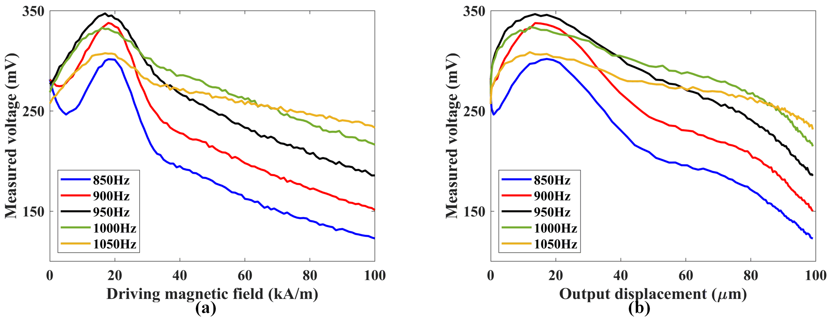
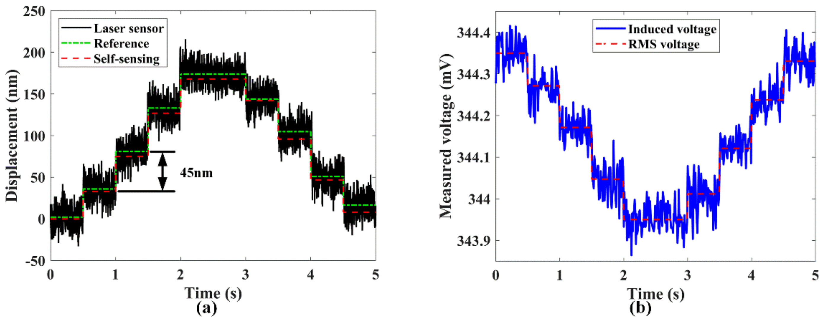
5.2. Self-Sensing Output Displacement Performance Test

At the conventional laboratory temperature (22 °C), the amplitude–frequency characteristic curves of the self-sensing signal were tested under a swept H s   for different values of H a , as shown in Figure 7. In the experiment, the amplitude of H s was set to 100 A/m, and its frequency ( f s ) was swept from 750 Hz to 1250 Hz. As H a increased from 10 kA/m to 100 kA/m, due to the ΔE effect of the GMM, the system’s resonance frequency ( f s r ) first decreased and then increased, with the minimum f s r occurring at H a = 20 kA/m. Comparing the different H a   conditions, the amplitude of the self-sensing signal reached its maximum at f s = f s r , and as f s r increased, the corresponding maximum amplitude of the self-sensing signal gradually decreased.
Based on the amplitude–frequency curves of the SSGMT’s self-sensing signal, the sensing characteristics under a fixed-frequency H s were experimentally measured (see Figure 8). When H a = 20 kA/m, f s r was near 950 Hz, so the experiments compared the self-sensing signal’s response at f s values of 850, 900, 950, 1000, and 1050 Hz under varying driving magnetic fields and output displacements. Figure 8a shows that the self-sensing signal varied nonlinearly with H a . Among the tested frequencies, f s = 950 Hz yielded the broadest range of monotonic variation with increasing H a .
Similarly, Figure 8b illustrates that the relationship between the self-sensing signal and output displacement is most monotonic at f s = 950 Hz. These results indicate that optimal displacement self-detection is achieved when f s is close to the system’s f s r at H a = 20 kA/m. Specifically, at f s = 950 Hz, increasing H a from 17 kA/m to 100 kA/m increased the output displacement from 13.6 μm to 95.6 μm, while the self-sensing signal decreased steadily from 345.6 mV to 185.7 mV. To ensure reliable performance, the SSGMT was designed to operate continuously under a bias magnetic field provided by permanent magnets, thereby avoiding interference caused by non-monotonic signal variations in the low-field region.
Then, the output displacement self-detection resolution of SSGMT without load was measured. During the test, the driving magnetic field was first adjusted to 20 kA/m, and then the open-loop step positioning test was conducted based on the SSGMT prototype. The experimental results of SSGMT output displacement measured by laser sensor in real time are shown in Figure 9a. The displacement output resolution can reach 45 nm under current laboratory conditions. At the same time, the induced voltage signal detected by the sensing coil is shown in Figure 9b, and an obvious step-change trend can be observed. The RMS value of the detected induced voltage signal is converted into the detected displacement by using the self-sensing drive model established in ref. [19] considering the influence of magnetic–mechanic–thermal coupling hysteresis. The results of self-sensing detection are compared with those of the laser sensor, and the maximum error is less than 10 nm. The above experimental results show that the SSGMT has the ability to realize micro- and nano-level precision self-sensing drive.

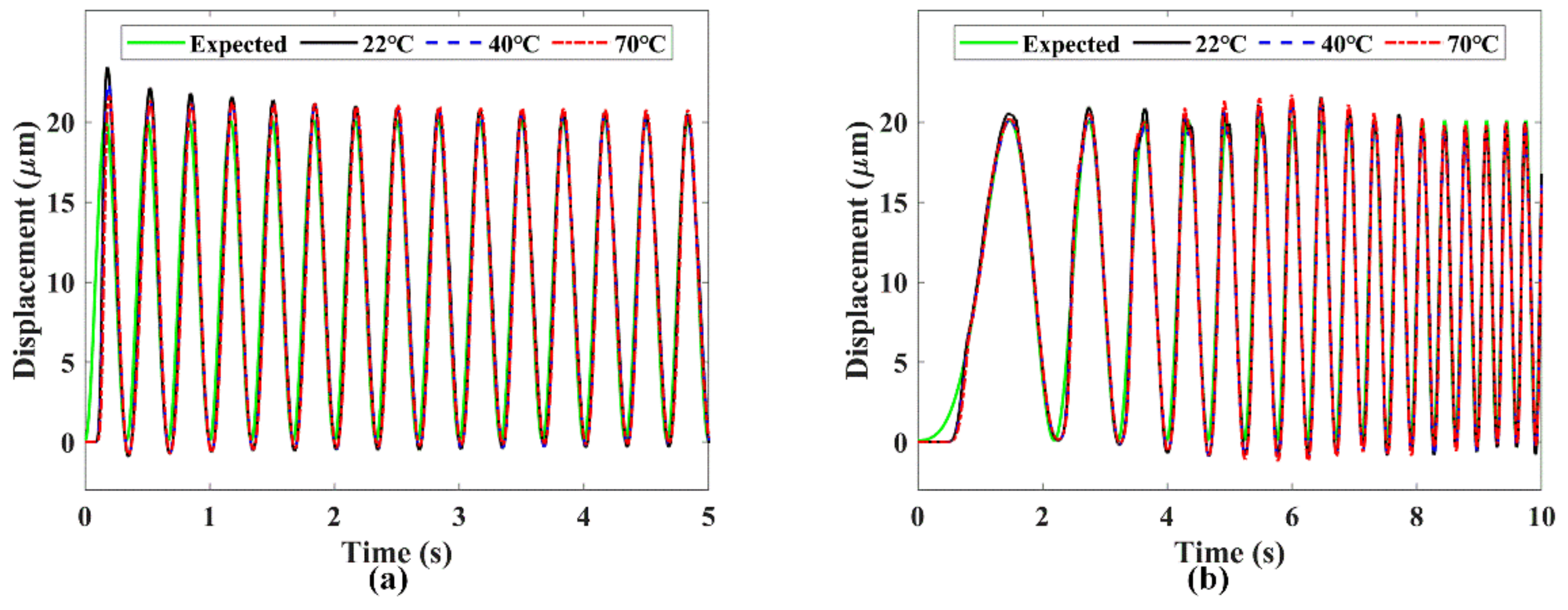
5.3. Trajectory Tracking Test

Based on the previous section’s test results of the SSGMT’s self-sensing drive performance and the research foundation for achieving self-sensing precise positioning, this section tests the trajectory tracking performance of the SSGMT based on self-sensing at different temperatures. First, the frequency response of the SSGMT at different temperatures was measured. A micro-amplitude random waveform current ranging from 0.1 Hz to 100 Hz was input into the driving coil of the SSGMT, and the output displacement was measured. Using the method from ref. [19], a 20th-order FIR filter was employed to estimate the frequency response of the SSGMT. The model identification results were compared with the self-sensing detection experimental results, as shown in Figure 10. From the experimental results in the figure, it can be seen that the SSGMT’s output remains stable within the 100 Hz bandwidth at different temperatures, meeting the performance requirements for use.
The hysteresis nonlinearity of the SSGMT was further identified and modeled. In this section, the improved PI model based on polynomial operator proposed in ref. [19] is directly used to identify the static hysteresis of the SSGMT. Based on the self-sensing drive performance test results, the bias magnetic field of SSGMT was first adjusted to 25 kA/m via permanent magnet bias and a small static current in the experiment. To avoid the influence of dynamic characteristics, a sinusoidal current with an amplitude from 0.4 A to 2 A and a frequency of 0.1 Hz was fed to the drive coil. The self-sensing signal was detected through the sensing coil, and the self-sensing signal was converted into the output displacement based on the self-sensing drive model. Using experimental data as the input and output data of hysteresis model, the weight vector of the play operator and polynomial operator of positive and inverse hysteresis loop were identified. The play operator weight vector w ^ H   and the polynomial operator weight vector w ^ p of the SSGMT inverse hysteresis model H 1 ( · ) are shown in Table 2. The identification results of the SSGMT static hysteresis positive model and inverse model are compared with the experimental results at a temperature of 22 °C, as shown in Figure 11. Compared with the experimental data, the relative root mean square (RRMS) error is less than 1.77%.
At standard laboratory temperature (22 °C), current signals at different frequencies (0.5, 1, 5, and 10 Hz) were applied to the SSGMT. The actual outputs obtained from self-sensing signals were compared with the outputs generated by the identified model. The comparison results are shown in Figure 12. As observed from the figure, the hysteresis behavior of the SSGMT became more pronounced with increasing frequency. The dynamic hysteresis model based on the Hammerstein structure accurately captures the system’s output response across the tested frequencies. Under the temperature condition of 22 °C, within the frequency range of 0.5–10 Hz, the root mean square (RMS) error of the model identification results remains below 1.7 μm, and the RRMS error is within 2.4%.
The same experimental procedure was repeated to identify the dynamic hysteresis model of the SSGMT under different temperature conditions. The temperature chamber used in this experiment refers to the design described in ref. [19]. The model outputs were compared with the self-sensing experimental results, as illustrated in Figure 13. In the figure, ‘EXP’ represents the self-sensing measurement results, while ‘SIM’ denotes the outputs of the identified model. It can be observed that the Hammerstein-structured dynamic hysteresis model accurately captures the output behavior of the SSGMT across various temperatures. A comparison between the identified model and the experimental data under different temperatures and excitation frequencies shows that the RMS error remains within 1.9 μm, and the RRMS error is within 2.8%. Therefore, the Hammerstein-based dynamic hysteresis model constructed in this section proves to be effective in predicting the nonlinear output characteristics of the SSGMT under varying temperature and actuation frequency conditions.
Finally, based on the preceding research, we conduct experimental testing to evaluate the trajectory tracking performance of the SSGMT. The experimental setup is shown in Figure 6. Two types of reference trajectories with distinct waveforms were used in the tracking tests. The first is a sinusoidal waveform with an amplitude of 20 μ m and a frequency of 3 Hz, while the second is a swept-frequency waveform ranging from 0.1 Hz to 5 Hz, also with an amplitude of 20 μm. The corresponding tracking performance results are illustrated in Figure 14. The steady-state tracking errors under different temperature conditions and waveform types (measured after 3 s of continuous tracking) are summarized in Table 3.
The above experimental results demonstrate that the SSGMT is capable of achieving precise trajectory tracking under different temperatures and input frequencies. The research provides a theoretical and practical foundation for subsequent applications in lathe operations.

6. Conclusions

This paper proposes a self-sensing giant magnetostrictive actuator-based turning tool (SSGMT) to address the challenges of compactness, precision, and real-time feedback in intelligent machining. A comprehensive multi-physical model was established to capture the coupled magnetic, mechanical, and thermal behaviors of the actuator. Additionally, a dynamic hysteresis model based on a Hammerstein structure was developed to describe the rate-dependent nonlinear response of the system. To ensure optimal system performance under physical and structural constraints, a multi-objective optimization framework was constructed to guide the design of key parameters, balancing actuation force, energy efficiency, sensing signal quality, and structural compactness.
Based on the optimized parameters, a prototype of the SSGMT was fabricated and tested. Experimental evaluations demonstrated high-resolution self-sensing displacement capabilities with sub-100 nm precision and robust performance across varying thermal and dynamic conditions. A hybrid control scheme combining inverse hysteresis compensation and adaptive feedforward control was implemented to improve trajectory tracking accuracy. The system showed effective suppression of nonlinear distortion and maintained high positioning precision in both static and dynamic tracking tests. These results validate the feasibility and effectiveness of integrating actuation and sensing within a unified structure and provide a promising foundation for deploying self-sensing actuators in next-generation ultra-precision machining tools.
Future research will prioritize enhancing the self-sensing signal quality through advanced coil topologies and adaptive signal processing techniques to achieve sub-10 nm resolution under dynamic machining loads. Concurrently, efforts will focus on extending the operational bandwidth beyond 100 Hz via real-time hysteresis compensation algorithms for complex surface machining applications. Further validation in industrial environments—including robustness testing against coolant immersion, electromagnetic interference, and thermal transients (20–120 °C)—will be conducted to bridge laboratory prototypes and production-ready systems. The fundamental SSGMT architecture will also be adapted to milling tools and multi-axis smart tooling platforms.

Author Contributions

Conceptualization, methodology, D.X. and B.Y.; experiment, D.X. and Y.Z.; formal analysis, Y.Y.; writing—original draft preparation, Q.W.; writing—review and editing, D.X. and Q.W.; visualization, D.X.; supervision, B.Y.; project administration, B.Y. and C.Z. All authors have read and agreed to the published version of the manuscript.

Funding

This work is supported by the National Key R&D Program of China (2022YFB3902703), the National Natural Science Foundation of China (52173239), the Specific Project of SJTU for “Invigorating Inner Mongolia through Science and Technology” (2022XYJG0001-01-04), and the Startup Fund for Young Faculty at SJTU (24X010500146).

Data Availability Statement

The data are contained within the article.

Acknowledgments

The authors would like to express their sincere gratitude to the journal editors and reviewers for their meticulous work and valuable advice.

Conflicts of Interest

The authors declare no conflicts of interest.

References

  1. Bleicher, F.; Biermann, D.; Drossel, W.-G.; Moehring, H.-C.; Altintas, Y. Sensor and Actuator Integrated Tooling Systems. CIRP Ann. 2023, 72, 673–696. [Google Scholar] [CrossRef]
  2. Zhou, C.; Guo, K.; Sun, J. An Integrated Wireless Vibration Sensing Tool Holder for Milling Tool Condition Monitoring with Singularity Analysis. Measurement 2021, 174, 109038. [Google Scholar] [CrossRef]
  3. Bleicher, F.; Ramsauer, C.M.; Oswald, R.; Leder, N.; Schoerghofer, P. Method for Determining Edge Chipping in Milling Based on Tool Holder Vibration Measurements. CIRP Ann. 2020, 69, 101–104. [Google Scholar] [CrossRef]
  4. Zhang, P.; Gao, D.; Lu, Y.; Ma, Z.; Wang, X.; Song, X. Cutting Tool Wear Monitoring Based on a Smart Toolholder with Embedded Force and Vibration Sensors and an Improved Residual Network. Measurement 2022, 199, 111520. [Google Scholar] [CrossRef]
  5. Mohamed, A.; Hassan, M.; M’Saoubi, R.; Attia, H. Tool Condition Monitoring for High-Performance Machining Systems—A Review. Sensors 2022, 22, 2206. [Google Scholar] [CrossRef]
  6. Mishra, D.; Pattipati, K.R.; Bollas, G.M. Intelligent Feature Engineering for Monitoring Tool Health in Machining. In Industry 4.0 Driven Manufacturing Technologies; Kumar, A., Kumar, P., Liu, Y., Eds.; Springer Nature: Cham, Switzerland, 2024; pp. 37–67. ISBN 978-3-031-68271-1. [Google Scholar]
  7. Deshpande, S.; Araujo, A.C.; Lagarrigue, P. Identification of Material Layer During Helical Milling Process on Aerospace Stacks Using Spindle Power Data; Elsevier: Amsterdam, The Netherlands, 2025. [Google Scholar]
  8. Hu, S.; Yang, Y.; Bao, W.; Nie, Y. Research on the Control System and Method of Cutting Arms for Digital Twin Driven Excavation Equipment. In Proceedings of the 2024 9th International Conference on Intelligent Computing and Signal Processing (ICSP), Xi’an, China, 19–21 April 2024; pp. 1475–1480. [Google Scholar]
  9. Huber, J.E.; Fleck, N.A.; Ashby, M.F. The Selection of Mechanical Actuators Based on Performance Indices. Proc. R. Soc. London. Ser. A Math. Phys. Eng. Sci. 1997, 453, 2185–2205. [Google Scholar] [CrossRef]
  10. Ceyssens, F.; Sadeghpour, S.; Fujita, H.; Puers, R. Actuators: Accomplishments, Opportunities and Challenges. Sens. Actuators A Phys. 2019, 295, 604–611. [Google Scholar] [CrossRef]
  11. Wang, S.; Rong, W.; Wang, L.; Xie, H.; Sun, L.; Mills, J.K. A Survey of Piezoelectric Actuators with Long Working Stroke in Recent Years: Classifications, Principles, Connections and Distinctions. Mech. Syst. Signal Process. 2019, 123, 591–605. [Google Scholar] [CrossRef]
  12. De Vicente, J.; Klingenberg, D.J.; Hidalgo-Alvarez, R. Magnetorheological Fluids: A Review. Soft Matter 2011, 7, 3701–3710. [Google Scholar] [CrossRef]
  13. Maiwald, D.; Bucht, A.; Zorn, W.; Drossel, W.-G. Development Approach of Actuators for High Loads Based on Shape Memory Alloys. In Proceedings of the ASME 2020 Conference on Smart Materials, Adaptive Structures and Intelligent Systems, Virtual, Online, 15 September 2020. [Google Scholar]
  14. Yoshioka, H.; Shinno, H.; Sawano, H. A Newly Developed Rotary-Linear Motion Platform with a Giant Magnetostrictive Actuator. CIRP Ann. 2013, 62, 371–374. [Google Scholar] [CrossRef]
  15. Zhu, Z.; Zhou, X.; Liu, Z.; Wang, R.; Zhu, L. Development of a Piezoelectrically Actuated Two-Degree-of-Freedom Fast Tool Servo with Decoupled Motions for Micro-/Nanomachining. Precis. Eng. 2014, 38, 809–820. [Google Scholar] [CrossRef]
  16. Li, H.; Ibrahim, R.; Cheng, K. Design and Principles of an Innovative Compliant Fast Tool Servo for Precision Engineering. Mech. Sci. 2011, 2, 139–146. [Google Scholar] [CrossRef]
  17. Huang, W.-W.; Li, L.; Zhu, Z.; Zhu, L.-M. Modeling, Design and Control of Normal-Stressed Electromagnetic Actuated Fast Tool Servos. Mech. Syst. Signal Process. 2022, 178, 109304. [Google Scholar] [CrossRef]
  18. Yoshioka, H.; Kojima, K.; Toyota, D. Micro Patterning on Curved Surface with a Fast Tool Servo System for Micro Milling Process. CIRP Ann. 2020, 69, 325–328. [Google Scholar] [CrossRef]
  19. Xie, D.; Yang, Y.; Zhang, Y.; Yang, B. Precision Positioning Based on Temperature Dependence Self-Sensing Magnetostrictive Actuation Mechanism. Int. J. Mech. Sci. 2024, 272, 109174. [Google Scholar] [CrossRef]
  20. Xie, D.; Yang, Y.; Yang, B. Self-Sensing Magnetostrictive Actuator Based on ΔE Effect: Design, Theoretical Modeling and Experiment. Smart Mater. Struct. 2022, 31, 055007. [Google Scholar] [CrossRef]
  21. Kim, H.-S.; Lee, K.-I.; Lee, K.-M.; Bang, Y.-B. Fabrication of Free-Form Surfaces Using a Long-Stroke Fast Tool Servo and Corrective Figuring with on-Machine Measurement. Int. J. Mach. Tools Manuf. 2009, 49, 991–997. [Google Scholar] [CrossRef]
  22. Zhong, E.; Wang, S.; Zhai, C.; Li, W. Improved Non-Singular Fast Terminal Sliding Mode Control with Hysteresis Compensation for Piezo-Driven Fast Steering Mirrors. Actuators 2025, 14, 170. [Google Scholar] [CrossRef]
  23. Sun, X.; Liu, Y.; Hu, W.; Sun, T.; Hu, J. Design Optimization of a Giant Magnetostrictive Driving System for Large Stroke Application Considering Vibration Suppression in Working Process. Mech. Syst. Signal Process. 2020, 138, 106560. [Google Scholar] [CrossRef]
  24. Sun, X.; Wei, H.; Liu, Y.; Wang, Z.; Jun, H. Integrated Design and Simulation of a Giant Magnetostrictive Driving Positioning and Vibration Suppression System. J. Syst. Simul. 2021, 33, 358–365. [Google Scholar] [CrossRef]
  25. Barbisio, E.; Fiorillo, F.; Ragusa, C. Predicting Loss in Magnetic Steels under Arbitrary Induction Waveform and with Minor Hysteresis Loops. IEEE Trans. Magn. 2004, 40, 1810–1819. [Google Scholar] [CrossRef]
  26. Wang, D.; Tan, D.; Liu, L. Particle Swarm Optimization Algorithm: An Overview. Soft Comput. 2018, 22, 387–408. [Google Scholar] [CrossRef]
  27. Liu, C.; Jing, X.; Daley, S.; Li, F. Recent Advances in Micro-Vibration Isolation. Mech. Syst. Signal Process. 2015, 56–57, 55–80. [Google Scholar] [CrossRef]
  28. Kuhnen, K. Modeling, Identification and Compensation of Complex Hysteretic Nonlinearities: A Modified Prandtl-Ishlinskii Approach. Eur. J. Control. 2003, 9, 407–418. [Google Scholar] [CrossRef]
Figure 1. Mechanical structure of SSGMT: (a) external components; (b) internal structure.
Actuators 14 00302 g001
Figure 2. A schematic diagram of the energy flow during the operation of the SSGMT.
Actuators 14 00302 g002
Figure 3. (a) Magnetic circuit diagram and (b) equivalent magnetic circuit model of driving process for SSGMT.
Actuators 14 00302 g003
Figure 4. Block diagram of frequency-dependent Hammerstein model of SSGMT.
Actuators 14 00302 g004
Figure 5. Block diagram of trajectory tracking controller for SSGMT.
Actuators 14 00302 g005
Figure 6. The basic performance verification experiment of the SSGMT: (a) device connection diagram; (b) the prototype of the SSGMT.
Actuators 14 00302 g006
Figure 7. Experimental curves of amplitude–frequency characteristics of self-sensing signal of SSGMT under different Ha values at normal temperature (22 °C).
Actuators 14 00302 g007
Figure 8. Experimental curves of self-sensing signal of SSGMT under different fs values versus (a) driving magnetic field and (b) output displacement.
Actuators 14 00302 g008
Figure 9. Output displacement self-detection resolution of SSGMT: (a) comparison of self-sensing detection and laser sensor detection; (b) detected self-sensing signal.
Actuators 14 00302 g009
Figure 10. Frequency response of SSGMT at different temperatures.
Actuators 14 00302 g010
Figure 11. Experimental identification results of (a) hysteresis loop and (b) inverse hysteresis loop of SSGMT at 22 °C.
Actuators 14 00302 g011
Figure 12. Magnetic hysteresis identification results of SSGMT when temperature is 22 °C at input frequency of (a) 0.5 Hz, (b) 1 Hz, (c) 5 Hz, and (d) 10 Hz.
Actuators 14 00302 g012
Figure 13. A comparison between the identification result (SIM) and the experimental result (EXP) of the SSGMT at different temperatures at an input frequency of (a) 1 Hz and (b) 5 Hz.
Actuators 14 00302 g013
Figure 14. The trajectory tracking effect of the SSGMT on (a) a 2 Hz fixed-frequency waveform and (b) a 0.1–5 Hz sweep waveform with expected displacement at different temperatures.
Actuators 14 00302 g014
Table 1. Optimization results of SSGMT design parameters.
ParameterValue RangeResultSelected Value
rm (mm)[4, 8]4.65
ra2 (mm)[8, 15]10.711
lca (mm)[100, 110]104.6105
dca (mm)[0.25, 0.5]0.380.4
lcs (mm)[18, 25]20.320
ty (mm)[1.5, 3]2.22
Table 2. Identified parameters of inverse hysteresis model of SSGMT.
ParameterValue Range
ŵH[1.4208, −0.9671, −0.0229, 0.0435, 0.1561,
−1.7034, 1.0543, −2.2107, 1.6592, −2.4592]
ŵp[−7.9794, −5.3456, 5.0142, −0.8762, 3.3423]
Table 3. Trajectory tracking steady-state errors of SSGMT at different temperatures.
Temperature (°C)Sinusoidal TrajectorySweep Trajectory
RMS (µm)RRMS (%)RMS (µm)RRMS (%)
220.9762.371.0562.60
401.0382.531.1292.79
701.1132.701.2593.11
Disclaimer/Publisher’s Note: The statements, opinions and data contained in all publications are solely those of the individual author(s) and contributor(s) and not of MDPI and/or the editor(s). MDPI and/or the editor(s) disclaim responsibility for any injury to people or property resulting from any ideas, methods, instructions or products referred to in the content.

