Abstract
Solving the common paradoxical problem between sub-micro-arc level resolution and a wide range of rotation angles in rotary actuators, this paper designs a single-drive compliant rotary mechanism (CRM) and develops a cross-scale compliant rotary actuator (CCRA). Specially, the proposed CRM employs a single-input–four-output divergent parallel configuration to transform a unidirectional input force into a rotational moment around the rotational center, effectively avoiding asynchronous motion and rotational center shift caused by the multiple actuation. Moreover, the CCRA is developed based on the CRM and a direct-drive rotary (DDR) motor, and adaptive switching between the macro- and micro-combination can simultaneously achieve large rotary range and sub-µrad resolution. After a series of modeling, mechanism optimization, and simulation, a prototype experimental system was built to further test the performance of proposed CCRA. The open-loop and closed-loop characterization experiments showed that the CRM can achieve a rotational resolution of 0.05 rad and a driving force of 0.78 N·m. In addition, the cross-scale switching experimental results show that the CCRA is able to achieve a static positioning accuracy of 3.5 rad within a rotational range.
1. Introduction
With the rapid development of precision manufacturing, the demand for nano-scale actuators in chip alignment operation and optical precision detection has continually increased [1,2]. The rotary actuator, as a core component for achieving rotational alignment operations, directly impacts the accuracy and yield of products [3]. For example, the latest manufacturing technology has pushed the chip size of microLEDs towards a 10 m size and 5 m pitch [4,5], requiring related rotary actuators to achieve <±5 rad angular alignment precision [6].
The stringent requirement above imposes two primary challenges for rotary actuators [7,8]: (1) sub-rad level rotary resolution to meet the global angular accuracy from the center of substrate to the edge (length over 300 mm) and (2) large stroke rotation consistency to maintain precision stability throughout a wide rotational range (beyond 10). At present, common rotary actuators are primarily classified into three configurations [9,10,11]: (1) gear-driven mechanical actuators, (2) Lorentz force-based electromagnetic direct-drive devices, and (3) flexure-based piezoelectric compliant mechanisms. Their characteristics are as follows:
- 1.
- Mechanical actuators: Due to the compounded effects of transmission backlash, manufacturing tolerances, mechanical vibrations, and nonlinear frictional phenomena, angular positioning errors exceeding 100 rad are induced.
- 2.
- Electromagnetic devices: The heat of the coil tends to cause the driving torque to drift, while the vibration and eccentricity of the rotor and stator make it difficult to further improve the rotational accuracy, which is usually about 20 rad.
- 3.
- Piezoelectric compliant mechanism: Compliant mechanisms are used to achieve nano-scale motion due to the advantage of no mechanical errors and no friction slipping. However, their practical application is constrained by the stroke limitations of the piezoelectric actuator (PEA), resulting maximum output angular range of <20 mrad.
Obviously, it is difficult to simultaneously achieve sub-rad level resolution and large stroke by using the conventional individual rotary actuation form above.
For this problem, recent research, such as that on inertial driving, compliant amplification mechanisms, and hybrid actuation methods, has been proposed to solve the contradiction between wide motion range and high positioning precision [12,13]. Based on the stick–slip actuated principle, researchers have developed linear inertial motors employing flexure-based piezoelectric actuators (PEAs) that can achieve motion stroke beyond 10 mm while maintaining positioning resolution less than 10 nm [14,15]. However, these inertial actuators exhibits inherent limitations of frictional slipping and backward motion and are susceptible to environmental disturbances [16]. Hence, another method is to use compliant mechanisms with a large amplification ratio to amplify the input displacement [17]. For example, bridge-type and lever amplifiers can achieve magnification ratios higher than 12 through connecting some optimized compliant mechanisms in series [18]. Yet serial amplification chains inevitably reduce mechanical structural stiffness, while increasing overall size proportionally to the amplification ratio [19]. Hence, parallel actuators with multiple amplification chains and multiple input sources have emerged to improve mechanical stiffness and dynamic property, but multiple inputs inevitably deteriorate coupling and deviation among the parallel motion chains, reducing the accuracy of actuators and leading to redundant actuation [20].
To solve the above problems, this paper designs a single-drive compliant rotary mechanism (CRM) with minimum redundant actuation characteristics and develops a cross-scale compliant rotary actuator (CCRA). The proposed CRM utilizes a single-input–four-output divergent parallel configuration to prevent asynchronous motion and rotational center shift caused by multiple actuation modes, achieving a rotation resolution at the sub-rad level. Further, a sensing and switching strategy based on a CRM and CCRA is developed to achieve smooth switching between wide-range rotation (macro-actuator) and high-precision positioning (micro-actuator). After a series of modeling, mechanical optimization, and FEA simulations, a prototype experimental system was built to validate the effectiveness of the CCRA. The experimental results show that the developed CCRA and cross-scale switching strategy can achieve sub-rad level angular resolution within stroke.
The major contribution of this paper is designing and developing a new cross-scale compliant rotary actuator with minimum actuation redundancy properties, simultaneously achieving sub-rad level angular resolution and wide rotation range. The rest of this paper is arranged as follows: Section 2 introduces the mechanical design of the CCRA. Section 3 illustrates the modeling process of the compliant rotary mechanism and dynamic performance. The mechanism optimization and finite element analysis (FEA) validation is displayed in Section 4. Section 5 details the experiments and performance evaluation of the CRM and CCRA, and Section 6 concludes the paper.
2. The Design of the Cross-Scale Compliant Rotary Actuator
In this section, a new compliant rotary mechanism (CRM) with a single drive is designed. The composition and design process of the CRM is described in detail. Then, a cross-scale compliant rotary actuator is designed based on the CRM and its working principle is described in detail.
2.1. The Issue Statement of the Traditional Compliant Rotary Actuator
Current compliant rotational mechanisms utilizing flexible hinges predominantly employ multiple piezoelectric stack actuators (PEAs) to drive two or three parallel kinematic chains for rotation [21], as shown in Figure 1. This multi-actuator configuration, however, introduces critical limitations. The use of multiple PEAs leads to negative issues such as input signal deviation, the asynchronous movement of the motion chains, and errors in the driving force between motion axes, ultimately causing a shift in the center of the rotational mechanism and generating a new alignment error [22], as shown in Figure 1b. Moreover, the presence of multiple driving sources introduces actuation redundancy, increasing both control complexity and cost, as shown in Figure 1a. Therefore, a single-input–four-output compliant rotational actuator driven by a single PEA can directly eliminate these problems, as shown in Figure 1c.
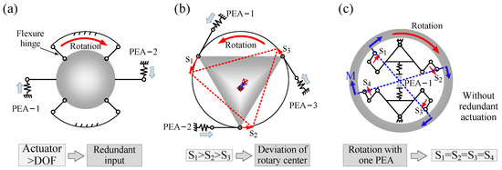
Figure 1.
Comparison of rotary actuators with different actuation configurations. (a) The rotational stage actuated by two PEAs. (b) The XY stage actuated by three PEAs. (c) The new rotary actuator configuration without redundant actuation.
2.2. The Design of the Compliant Rotary Mechanism with Single Actuation
Considering that a single PEA can only generate displacement along a specific direction, it is essential to design an appropriate compliant mechanism to convert and distribute the displacement of the PEA for achieving the desired rotational torque. To this end, four compact parallel motion chain mechanisms based on expanding the configuration from central to circumferential are innovatively designed, as shown in Figure 2a. This mechanism can transform the output force of a single PEA into four evenly distributed forces along the same rotational direction, thereby generating the synchronized rotary moment.
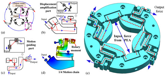
Figure 2.
Mechanical design process of compliant rotary mechanism (CRM). (a) Rotational actuation principle with single input property. (b) Compact displacement amplification mechanism with rotative configuration. (c) S-shaped guiding mechanism. (d) Displacement transmission diagram of single motion chain. (e) Designed CRM.
Based on the established configuration of the motion chains, the rotational motion chain structure is divided into a displacement amplification part and a motion guidance part. First, in the displacement amplification part, the circle flexible hinges with fixed pivot points on the same and opposite sides are designed to form a lever amplification mechanism, which can maximally ensure the position of rotational center during motion. The displacement direction is changed by 45 through a rotative structure, as shown in Figure 2b. Then, in the motion guiding part, an S-shaped guiding mechanism is designed, which is composed of a rounded-beam flexible hinge located on opposite sides, as illustrated in Figure 2c. This mechanism further transforms the displacement to the horizontal direction for generating the rotary moment around the center, as shown in Figure 2c. Ultimately, the two parts are combined in a series arrangement to form a complete rotational chain mechanism, as depicted in Figure 2d.
Subsequently, the four designed rotational chain mechanisms are evenly arranged around the rotary center, as shown in Figure 2e. This structural configuration not only facilitates efficient displacement transmission but also enhances the structural stability and load-bearing capacity at the output end. When the PEA exerts an input force and displacement at the input position, the motion is transmitted to the four output ends through the rotational chain mechanism. Finally, their resultant moments effectively produce a rotational effect around the center. Compared to traditional rotational chain structures, the designed rotational chain mechanisms require only one PEA to obtain rotational motion around the fixed central axis, possessing the advantage of minimal actuator redundancy.
However, although the compliant rotary mechanism with a large amplification ratio is designed, achieving a range of rotational motion remains challenging. Therefore, it is essential to further enhance the operational range.
2.3. Working Principle of Cross-Scale Compliant Rotary Actuator
To extend the rotational stroke of the designed compliant rotary mechanism (CRM), a cross-scale compliant rotary actuator (CCRA) is developed by integrating a direct-drive rotary (DDR) motor with the CRM, as shown in Figure 3a. Meanwhile, four sets of high-precision strain gauge sensors are employed to measure the deformation and output displacement of the flexible hinges at the output end of each motion chain in real time, as shown in Figure 3b. The operational process of the designed cross-scale compliant rotary actuator can be described in two phases:
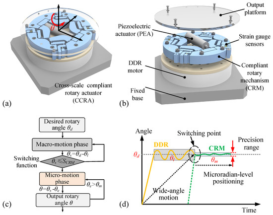
Figure 3.
Working principle of CCRA. (a) CCRA. (b) Components and assembly method of CCRA. (c) Workflow of CCRA. (d) Switching process of rotary precision.
- 1.
- Macro-motion large stroke phase: The DDR executes a large rotary stroke when the target angle exceeds the maximal rotary range of the CRM. But inherent positioning errors, , still exist due to mechanical backlash and the vibration of the DDR, resulting in static errors, ( = ), as shown in Figure 3c.
- 2.
- Micro-motion fine adjustment phase: Subsequently, the residual errors of the DDR are compensated by driving the PEA and the four compliant mechanism chains in the CRM, further improving the final rotary accuracy of the CCRA ( = ). Among them, represents the final positioning error of the CRM, which can achieve a sub-rad level angular precision. The entire switching process of the rotational motion is illustrated in Figure 3d.
It is important to note that during the above cross-scale switching process, the output angle of the DDR in the macro-motion phase is measured by using an arc grating scale, while the angle of the CRM in the micro-motion phase is detected by strain gauges mounted on the surface of flexible hinges. By combining the corresponding motion relationship model and cross-scale switching function, the developed rotary system can simultaneously achieve sub-rad level angular precision and large stroke rotation.
3. Modeling and Analysis of the Compliant Rotary Mechanism
This section performs the modeling of the compliant rotary mechanism to obtain the structural stiffness, displacement amplification, and dynamic property. It is used as the theoretical model for the subsequent optimization and the feedback sensing relationships.
3.1. Flexibility Modeling of the CRM
To characterize the input–output relationship of the designed compliant rotary mechanism (CRM), a static analytical model is established. Given that the motion transmission of the CRM primarily relies on elastic deformations of flexible hinges, these flexible hinges are selected as the critical elements for deformation analysis. Usually, the continuous integration method can be used for the analysis of micro-deformation [23,24]. Taking the straight beam flexible hinge as an example, when the movable end of the straight beam flexible hinge is rotated around the Z-axis of the fixed end by the external force , as shown in Figure 4, the bending moment can be expressed as
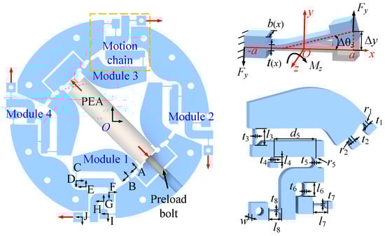
Figure 4.
A structure and deformation analysis diagram of the CRM.
Furthermore, introducing the boundary conditions, the angle equation at the position x of the flexible hinge can be further expressed as
where is the moment of inertia of the flexible hinge section (variable cross-section or constant cross-section), the straight beam hinge can be selected as , and b and t are the sizes of the cross-section.
Finally, the corresponding flexibility factor of the complete straight beam flexible hinge (length l and thickness t) can be defined by the angular deflection and force .
The relationship between the deformation , flexibility factor C, and force F or moment M in the direction i (i = x, y, ) can be obtained by using the above calculation method. Its general form of expression in the plane is as follows:
Similarly, the flexibility matrix parameters of the straight circular flexible hinge can be also derived. After obtaining the basic hinge model of the CRM, it is necessary to further establish the coordinate transformation matrix to solve the overall flexibility matrix from the input to the output. The corresponding transformation matrix from position i to position j can be expressed as
where T and R denote the translation transformation matrix and rotation transformation matrix, respectively. They can be further described as
where p = [, ] denotes the translation vector in x-y plane, is the rotation angle about the Z-axis.
As shown in Figure 4, the CRM comprises four identical kinematic motion chains. So, one of the motion chains can be analyzed for the convenience of calculation. According to the sequence of Figure 4, the straight circle flexible hinges A (input point) and B (support point) constitute the structure of the first-stage lever-amplifying mechanism, whereas the straight beam flexible hinge C simultaneously takes as the output of the first stage and input point of the second-stage mechanism, wherein the flexible hinge A is connected in parallel with the flexible hinge B and then connected in series with the flexible hinge D. Thus, the flexibility matrix from the hinge A to the hinge D can be expressed as
Similarly, by combining the series and parallel relationships, the flexibility matrix at point D, including the flexibility of the flexible hinge at that point itself, can be expressed as
Further, the flexibility matrix , at points F and J of the CRM can also be expressed, respectively, as
So far, the output flexibility matrix of a single motion chain within the CRM has been derived. Similarly, the output flexibility matrices , , and of the remaining three modules can be obtained using an analogous methodology. Then, according to the parallel relationship, the overall output matrix of the CRM can be described as
In summary, the flexibility matrix from the input to the output of the designed CRM is established successfully. Based on these analysis models and F = x/C, the corresponding input–output relationship and amplification ratio is subsequently obtained, which also provides a theoretical basis for the optimization of the structural performance.
3.2. Kinematic Analysis of the CRM
To establish analytical models for the kinematic relationships and displacement amplification ratio (DAR) of the proposed CRM, the geometric relationship of the motion chain in the deformation process is further analyzed. First, the deformation process of the displacement amplifying mechanism and the motion guiding mechanism is simplified to the ideal motion of the link, as shown in Figure 5. According to the deformation relationship of the mechanism, taking the motion of the key points A and G as examples, the instantaneous velocity can be expressed as
where is known to be /4, is the length of the corresponding simplified link i, and is the angular velocity of the corresponding point between i and j. Similarly, the angular displacement of the corresponding point can be solved by the above geometric relationship:
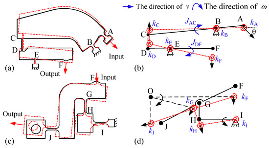
Figure 5.
Analysis diagram of module 1 in CRM. (a,b) Dynamic analysis diagram of displacement amplifying mechanism. (c,d) Dynamic analysis diagram of displacement guiding mechanism.
Further, from the geometrical relations of the simplified diagram, the amplification ratio of the CRM can be derived as
The amplification ratio model describes the proportional relationship between the input and output of the designed mechanism. A larger amplification ratio is prone to increasing the output displacement but at the same time reduces the structural stiffness. Therefore, a trade-off must be made between the displacement amplification ratio and the dynamic characteristics.
3.3. Dynamic Modeling of the CRM
Combining the kinematic relationships of the mechanism obtained above, the intrinsic frequency of the structure is further solved, which is a key factor describing the dynamic characteristics of the mechanism. According to the Lagrangian method [25], the dynamic modeling of the mechanism can be described as follows:
where T and U are the total kinetic energy and potential energy of module 1, and is the input displacement.
A simplified dynamics model of module 1 is shown in Figure 5b,d, where the flexible hinge is simplified as an equal-stiffness torsion spring. Meanwhile, the rotation in the plane is only considered because the flexible hinge has high stiffness in its non-operating direction. Following the relationships and annotation shown in Figure 5b,d, the total kinetic energy of module 1 under the input displacement of can be expressed as
where and denote the mass and rotational inertia of the link i, respectively.
Meanwhile, since the deformation in the compliant mechanism is focused on flexible hinges, only the potential energy of flexible hinges needs to be taken into account. Hence, the total potential energy of module 1 can be described as
where and denote the stiffness of the flexible hinge i and rotational angle.
By systematically solving the above equations from Equation (10) to Equation (17), and converting them to a standard dynamic equation form (), then, based on the vibration theory and dynamic equations, the first structural frequency of module 1 in the CRM can be derived by solving the eigenvalue equation of the dynamic equation under harmonic excitation.
where and are the output stiffness and mass of module 1 in the CRM, respectively.
In summary, the static and dynamic modeling of the key structures in the CRM has been successfully performed, and it was used to guide the subsequent optimization process of the structural parameters and simulation verification.
4. Optimization and Simulation of the Compliant Rotary Actuator
To further improve the output characteristics of the designed compliant rotary mechanism (CRM), the key structural sizes were optimized based on the established theoretical model. Meanwhile, the optimized CRM was simulated and analyzed to verify the working performance.
4.1. Parameter Optimization of the Compliant Rotary Actuator
Flexible hinges are used as the main structures in the CRM to generate deformations and transform motions, so their structural sizes directly affect the output displacements and structural dynamic properties of the CRM. Therefore, it was necessary to optimize the structural dimensions of the key flexible hinges for obtaining an optimal output displacement amplification ratio, , and output consistency between four motion chains. Based on the analytical model obtained above, the output consistency can be described by the output deviation between module 1 and module 2:
First, to simplify the computational amount and the space for iterations during the optimization process, the range of variables was further narrowed based on the preliminary result of finite element analysis (FEA). Finally, the optimization process for the key structural sizes (see Figure 4) of the CRM can be described as follows:
- 1.
- Optimization objectives: Max. and min. .
- 2.
- Optimization parameters: Sizes in module 1: , , , ; sizes in module 2: , .
- 3.
- Constraint conditions:
- (a)
- Input stiffness: < 0.45 (stiffness of PEA is 35 N/m).
- (b)
- Structural frequency: > 500 Hz.
- (c)
- Parameter ranges: 2 mm > (, ) > 1 mm; 2.5 mm > () > 1.5 mm; 1.5 mm > (, ) > 0.5 mm; 1 mm > (, , , , , ) ≥ 0.5 mm; 8 mm > > 4 mm; 3 mm > ≥ 2 mm; 6 mm > (, ) > 3 mm; 5.5 mm > (, ) > 3.5 mm; 18 mm > > 12 mm.
Combined with the output flexibility model established in the previous section and initial conditions, iterative optimization calculations were carried out using the multi-objective genetic algorithm (MOGA) in the optimization tool. The initial and iteration sample sizes were 150, and the optimization end condition was fixed at 20 times. Finally, the group with the optimal performance was selected from all the optimization results. When the input displacement was set to 10 m, the output displacements of module 1 and module 2 were 81.67 m and 81.41 m ( was about 8.1), respectively. The corresponding optimization results of the CRM are shown in Table 1, which were used as the basis for subsequently carrying out simulation verification and experimental testing.

Table 1.
Optimized parameters.
4.2. FEA of the Compliant Rotary Actuator
Based on the optimized CRM, simulation analyses evaluating aspects such as input–output stiffness, the amplification ratio of displacement, structural modality, and the output coupling effect were carried out using Ansys workbench software to verify the operational performance of the CRM.
4.2.1. Static Analysis
First, due to its good strength and lightweight characteristics, the commonly used material Al7075-T6 was selected as the simulation material of the CRM. To ensure that the PEA used in the input point could fully drive the CRM, the input and output stiffnesses were analyzed, as shown in Figure 6a. When an input force of 100 N is applied to both sides of the input point in the CRM, displacements of approximately 5.87 m and 5.86 m can be produced at the input and output points, respectively. This result indicates that the input stiffness of the CRM is about 17.06 N/m (lower than the output stiffness of the PEA). Therefore, the PEA can efficiently drive the CRM.
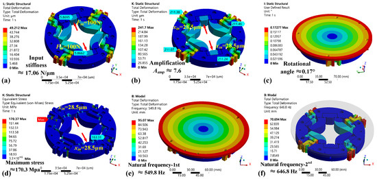
Figure 6.
The FEA analysis results for the CRM. (a) Input stiffness analysis. (b) Analysis of displacement amplification ratios. (c) Output angle analysis. (d) Maximum stress analysis of the CRM. (e,f) Structural modal analysis of the CRM.
Additionally, the displacements at output point of the four motion modules are 211.38 m, 211.07 m, 211.24 m, and 211.46 m, respectively (see Figure 6b) when a nominal displacement 28.5 m of the PEA is applied to the input point, indicating that the four modules of the CRM have high output consistency, with an error of less than 1 m. From the results, the displacement amplification ratio of the CRM is about 7.4, which has an error of about 8.6% with the calculated results. These results prove that the designed CRM can ensure the synchronization of output.
Finally, the nominal rotational displacement that can be produced on the output platform of the CRM was analyzed, as shown in Figure 6c. The simulation results show that the output motions of the four modules can be exactly composited into a rotation about of 0.17 (about 2.97 mrad). Moreover, the maximum equivalent stress of the flexible hinge of CRM during rotation is about 170.3 Mpa (see Figure 6d), which fully satisfies the yield strength of the material.
4.2.2. Dynamic Analysis
In addition, the structural modal of the CRM was analyzed to determine its optimal operating frequency range and dynamic property. The results of the modal analysis are shown in Figure 6e,f. It can be seen that the modal frequencies of the designed CRM for the first to second orders are approximately 549.8 Hz and 646.8 Hz, respectively. These values are significantly higher than the desired frequency for practical applications, indicating that the structure exhibits excellent dynamic characteristics.
In summary, all the simulation and analysis results show that the designed CRM is capable of generating the required high-precision rotary motion with a single PEA.
5. Experimental Test and Results and Discussion
In this section, we describe how, based on the optimized compliant rotary mechanism (CRM), a testing system for the cross-scale compliant rotary actuator was built to carry out performance verification, including open-loop and closed-loop experiments with the CRM. Finally, the switching performances between the stroke and precision of the cross-scale compliant rotary actuator (CCRA) were also further tested.
5.1. Experimental Setup
Based on the previous design analysis and simulation results, a corresponding experimental system was built to carry out performance testing and verification. Firstly, the Al7075-T6 material with high stiffness characteristics was integrated and processed by wire electrical discharge machining to obtain the designed micro-rotating platform, as shown in Figure 7. The CRM was driven by a PEA (Coremorrow-Pst 150/10/60 VS15) and a voltage amplifier (PI-E-503). The driving signals were generated using Matlab and a dSpace rapid prototyping system. Meanwhile, the output rotation angle was measured by an external rotary scale (Renishaw-RKLC40-S), a capacitive displacement sensor (NS-DCS14, SYMC, resolution: 20 nm), and high-precision strain gauges (TP-3.8-120-5-3). The strain gauges and signal conditioner were used to form a closed-loop control system. In addition, the CRM was connected in series to a macro-DDR motor (FE3-004-S-D-1; precision: ±30 arc sec; motion stroke: 360) to build a cross-scale rotary actuator. All devices were fixedly mounted on the vibration isolation platform (WN01AL, Winner Optics Instruments Group, Beijing, China).
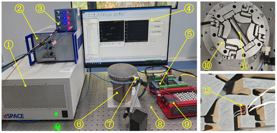
Figure 7.
Experimental system of CCRA. (1) dSpace rapid prototyping system. (2) Voltage amplifier. (3) Capacitive displacement sensor. (4) PC. (5) Control card for DDR. (6) DDR. (7) Detection head. (8) Vibration isolation platform. (9) Signal conditioner. (10) CRM. (11) PEA. (12) Strain gauges.
5.2. Open-Loop Test of the CRM
In order to determine the output precision, working stroke, and dynamic characteristics of the designed CRM, open-loop experiments were conducted. First, the relationship between the input voltage of the PEA and the corresponding displacements on both sides of the CRM input were tested by a capacitive displacement sensor, as shown in Figure 8a. When a voltage of 0∼120 V was applied to PEA, the two sides of the input point of the CRM could produce maximum input displacements of about 20.55 m and 20.67 m, respectively, with a conversion ratio of about 0.17 m/v. The experimental results show that the input linearity was approximately 94.6% within the input voltage range and the input characteristics at both input points had high consistency.
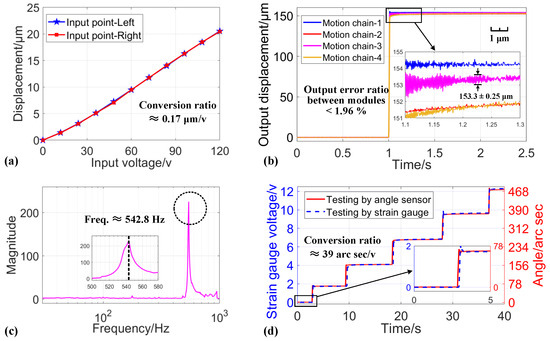
Figure 8.
Open-loop test of CRM. (a) Test of relationship between PEA voltage and input displacement. (b) Output displacement test of four motion modules. (c) Test of amplitude–frequency characteristics. (d) Calibration between different sensors.
Then, to further verify the output characteristics and consistency of the four motion modules, the output displacements were tested under a 120 V step input voltage, as shown in Figure 8b. The actual maximum output displacements of the four motion modules were 154.2 m, 151.8 m, 153.1 m, and 151.7 m, respectively. It appears that motion chain-2 and chain-4 had different transient behaviors, which may have been due to the deviations in manufacturing and measurement delays. Even so, the output deviation ratio between the four motion modules was less than 1.96%. Moreover, the actual displacement amplification ratio was about 7.3. Additionally, sweep tests were performed on the four output modules to obtain the amplitude–frequency characteristics using the Fourier transform, as shown in Figure 8c. The main resonant frequencies were about 542.8 Hz in the CRM. Due to unavoidable machining errors, there is an error between the test results and the simulation results. These test results indicate that the designed compliant motion modules had similar output characteristics.
Further, the voltage signals from the strain gauge affixed on the flexible hinges of the CRM and the measured values of the external angle sensors were calibrated for the convenience of measurement and feedback, as shown in Figure 8d. When the CRM was driven by an input voltage of 120 V, the angle sensor obtained a displacement of approximately 468 arc sec, while the corresponding output voltage signal from the strain gauge reached 12 V. Within the designed elastic deformation range, the calibration results revealed a conversion coefficient of 39 arc sec/V for the strain gauge relative to the angle sensor. Based on these open-loop performance tests and conversion relationships, closed-loop experiments were carried out subsequently.
5.3. Closed-Loop Test of the CRM
Based on the calibrated strain gauge sensor and displacement conversion principle, the rotational angle of the CRM can be acquired in real time. Hence, the resolution, positioning accuracy, and motion range of the CRM were further tested under closed-loop conditions with a proportional–integral (PI) controller. First, a step signal with a voltage change of 0.01 V was used as input to test the minimum rotational resolution that the CRM could generate stably, as depicted in Figure 9a. The minimum rotary resolution was about 0.01 arc sec (about 0.05 rad). Meanwhile, the motion accuracy of the CRM was tested under a continuous step signal input with a step size of 20, as shown in Figure 9b. The designed CRM was able to maintain a steady-state positioning accuracy of less than 0.4 arc sec (1.9 rad) throughout its travel range.
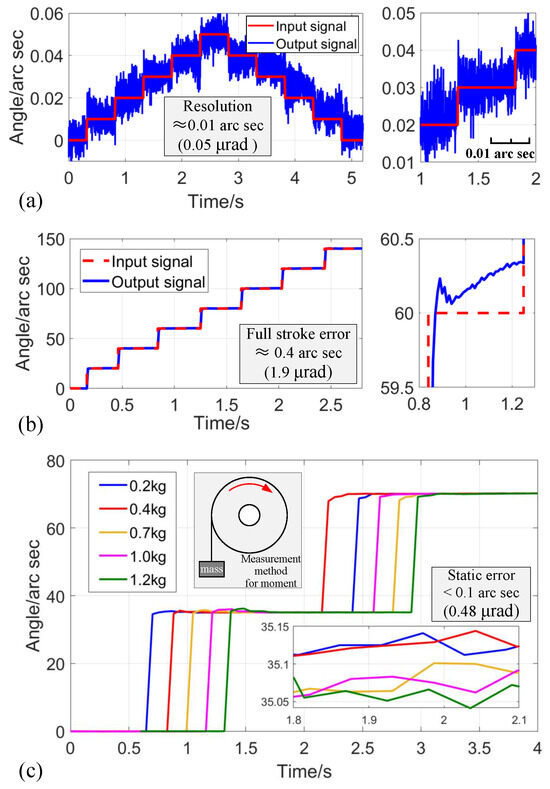
Figure 9.
The closed-loop test of the CRM. (a) The resolution of rotary motion. (b) The step accuracy of rotary motion. (c) Output accuracy under different driving loads.
Then, in order to verify the actuating capacity of the CRM, the output stability under different loads in the rotary direction (0.2 kg∼1.2 kg) and vertical direction (0 kg∼5 kg) was tested. As the driving load increased, the vibration and overshoot phenomenon at the output gradually became obvious, as shown in Figure 9c. Within a load range of 1.2 kg, the CRM maintained high motion consistency with a static error of less than 0.1 arc sec (about 0.48 rad). According to the test method of driving torque (see Figure 9c), the CRM could produce a stable driving torque of about 0.78 N·m.
Finally, tracking experiments were conducted using sinusoidal and triangular signal trajectories with frequencies ranging from 1 Hz to 10 Hz to verify the motion characteristics. Obviously, as shown in Figure 10, the tracking error increased gradually with motion frequency, and the error under a 10 Hz sinusoidal signal was about 1.1 arc sec (about 5.3 rad in Figure 10c). Due to the phenomenon of abrupt variation at the peak of the triangular wave signal, the tracking at this position was large, but the maximum error under the triangular trajectory of 10 Hz was still less than 2.4 arc sec (about 11.6 rad in Figure 10f). The dynamic trajectory tracking results show that the closed-loop feedback method based on strain gauge could guarantee the high-precision rotary alignment of the CRM in the low frequency range (below 10 Hz).
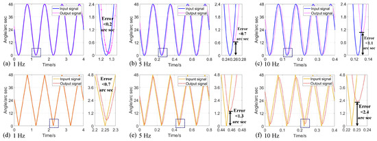
Figure 10.
Tracking experiments under different trajectories and frequencies. (a–c) Tracking results under sinusoidal signal of 1 Hz, 5 Hz, and 10 Hz. (d–f) Tracking results under triangular signal of 1 Hz, 5 Hz, and 10 Hz.
5.4. Switch Test of Cross-Scale Compliant Rotary Actuator
After verifying the performance of the CRM through the established strain gauge sensing method (see Figure 11a), the switching characteristics between the CRM and DDR were further tested. Hence, combining the rotational range and positioning accuracy of the CRM obtained from the previous closed-loop experiments, the following switching function and control strategy, as depicted in Figure 11, were designed to achieve a smooth switch between sub-rad level angular precision (CRM) and large-range rotation (DDR).
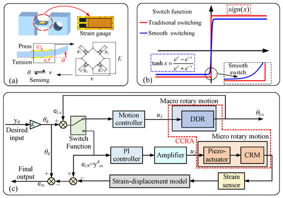
Figure 11.
Closed-loop feedback control strategy for CCRA. (a) Measurement principle of angle based on strain gauge. (b) Smooth switching function for cross-scale actuator. (c) Control strategy of cross-scale switching for CCRA.
First, the hyperbolic tangent function was used instead of the traditional sign switching function, which can reduce the shocks generated by the switching process (see Figure 11b). Meanwhile, according to the working process of the CCRA designed in Section 2.3, a control strategy for the CCRA was designed, as shown in Figure 11c. The integrated output characteristics of the CCRA at a desired rotation angle of were tested, as shown in Figure 12. When solely employing a DDR for rotational motion, the system achieved a positioning accuracy of approximately 0.003 (about 52.4 rad), as shown in Figure 12a. However, through the implementation of the CCRA and switching control strategy, residual positioning errors that persisted in the DDR could be further compensated, finally enabling a rotation accuracy less than 0.0002 (about 3.5 rad) (see Figure 12b).
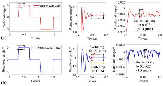
Figure 12.
Performance comparison between traditional rotational actuation and the designed CCRA. (a) The output performance of the conventional single DDR actuator. (b) The output performance of the designed CCRA.
Therefore, the experimental results demonstrate that the proposed CCRA and switching method can effectively solve the contradiction between the large rotational range and the sub-rad level accuracy in the rotary positioning and realize switching between stroke and accuracy.
5.5. Performance Evaluation and Discussion
In the experiments described above, the performance of the CCRA, including rotational resolution, accuracy, driving torque, and the effectiveness of the switching strategy, was thoroughly tested and validated. Meanwhile, comparisons of properties were performed with the same type of compliant rotary mechanism described in [21,26,27,28], as shown in Table 2. The designed CRM is driven by one PEA to generate rotary motion and it has minimum redundancy in the number of drives. The configuration of four rotary modules composed of flexible hinges also enhances the driving moment and loading capacity of the CRM. Finally, the designed CCRA is capable of achieving a rotary resolution of 0.05 rad and a driving moment of 0.78 N·m. Moreover, the designed cross-scale switching strategy enables the compliant rotary mechanism to achieve both high-precision (<3.5 rad) and wide-range () rotation. It should be noted that the switching settling time between the CRM and DDR is less than 10 ms (see Figure 12b), which can be improved by a composite controller. In summary, all experimental results show that the designed CCRA has superior resolution and rotational range.
Table 2.
Performance comparisons.
Additionally, the fatigue strength and thermal effects of compliant mechanisms under prolonged motion affect the stability of rotary actuators to some extent. Therefore, in future works, a feedback control algorithm based on temperature compensation can be introduced to enhance the stability of the CCRA. Meanwhile, appropriate heat treatment and the topological optimization of the fabricated compliant mechanisms should be implemented to improve their fatigue strength.
6. Conclusions
In this paper, a new cross-scale compliant rotary actuator (CCRA) with minimum actuation redundancy is designed, developed, and validated. The main contributions can be summarized as follows:
- 1.
- A compliant rotary mechanism (CRM) with minimal redundancy was innovatively designed, which can convert the linear motion of a single PEA into high-precision rotary motion through the single-input–four-output divergent parallel configuration.
- 2.
- Based on the designed CRM and DDR, a CCRA and cross-scale switching strategy that can simultaneously achieve high precision and a wide range of rotation were developed.
- 3.
- A series of optimizations, simulations, and experiments were successfully performed, and the results indicate the proposed CCRA can realize a rotational resolution of 0.05 rad and a rotational drive torque of 0.78 N·m. Moreover, a rotational accuracy of less than 3.5 rad can be achieved within a range of , which simultaneously realizes high precision and wide range during rotary positioning.
All the results consistently demonstrate that the developed CCRA and cross-scale switching strategy can effectively address the challenges between sub-rad accuracy and large-range rotation. In the future, some faster switching strategies and disturbance rejection control methods for CCRA will be investigated to further improve the switching speed and dynamic stability.
Author Contributions
Conceptualization, Y.J. and H.T.; methodology, Y.J. and J.C.; software, W.W. and Z.L.; validation, Y.J., W.W. and J.C.; formal analysis, Y.J., J.C. and Z.L.; investigation, Z.L. and W.W.; resources, H.T. and Y.T.; data curation, Y.J., J.C. and Z.L.; writing—original draft preparation, Y.J.; writing—review and editing, Y.J., H.T. and Y.W.; visualization, Y.J., J.C. and W.W.; supervision, H.T., Y.T. and Y.W.; project administration, H.T. and Y.T.; funding acquisition, H.T., Y.T. and Y.W. All authors have read and agreed to the published version of the manuscript.
Funding
This research was funded by the European Union Horizon 2020 research and innovation programme under the Marie Sklodowska-Curie Grant Agreement No. 101026104, the Guangdong Basic and Applied Basic Research Foundation under Grant 2025A1515010237, State Key Laboratory of Precision Electronics Manufacturing Technology and Equipment under Grant JDZ202314, and the Guangzhou Basic and Applied Basic Research Foundation under Grant 2025A04J3745.
Data Availability Statement
The numerical simulation and experimental data presented in this paper are available from the corresponding author upon reasonable request.
Acknowledgments
The authors would like to thank the the handling editor and anonymous reviewers for their useful comments and constructive suggestions.
Conflicts of Interest
The authors declare no conflicts of interest.
References
- Liang, Z.; Chen, Z.; Wu, Q.; Gao, X.; Zhang, X. Precision Alignment in Cell Microinjection Based on Hybrid Triple-View Micro-Vision. IEEE Trans. Robot. 2024, 40, 158–171. [Google Scholar] [CrossRef]
- Nishimura, Y.; Chujo, W.; Kobayashi, K. High-Precision Automatic Optical Axis Alignment of LED Backhaul in Lighting Surroundings Based on Object Detection. IEICE Commun. Express 2024, 13, 151–155. [Google Scholar] [CrossRef]
- Zheng, J.; Chen, G.; Wang, L.; Sheng, X.; Liu, X.; Gao, T.; Xu, X.; Zhao, P.; Wei, J. Alignment method for rotary stage axis and optical axis in the polar coordinate direct laser writing system. Opt. Eng. 2022, 61, 034104. [Google Scholar] [CrossRef]
- Bower, C.A.; Bonafede, S.; Raymond, B.; Pearson, A.; Prevatte, C.; Weeks, T.; Radauscher, E.; Vick, E.; Verreen, C.; Krongard, B.; et al. High-brightness displays made with micro-transfer printed flip-chip microLEDs. In Proceedings of the IEEE 70th Electronic Components and Technology Conference (ECTC), Orlando, FL, USA, 3–30 June 2020; pp. 175–181. [Google Scholar]
- Jia, Y.; Tang, H.; Xu, S.; Xu, Y.; Chen, X.; Tian, Y. A Novel Decoupled Flexure Nanopositioner with Thermal Distortion Self-Elimination Function. IEEE/ASME Trans. Mechatron. 2022, 27, 2953–2962. [Google Scholar] [CrossRef]
- Ma, L.; Chen, Y.; Chen, Y.; Chen, W.; Chen, X.; Hou, M.; Wong, C.P.; Niu, Y.; Yao, M. Experimental Study on Crack Propagation of Adhesive Layer Within Mini-LED Chips Needle-Ejecting Peeling-Off Transfer Mode. IEEE Trans. Compon. Packag. Manuf. Technol. 2024, 14, 951–960. [Google Scholar] [CrossRef]
- Searles, K.; Shalabi, N.; Jayhooni, S.M.; Takahata, K. A planar micro rotary actuator for endoscopic optical scanning. Sens. Actuator A Phys. 2022, 345, 113768. [Google Scholar] [CrossRef]
- Vargas-Chable, P.; Tecpoyotl-Torres, M.; Vera-Dimas, G.; Grimalsky, V.; Mireles García, J., Jr. Novel Electrothermal Microgrippers Based on a Rotary Actuator System. Micromachines 2022, 13, 2189. [Google Scholar] [CrossRef]
- Chen, T.; Zhang, Y.; Qiu, S.; Jiang, J.; Zhang, Q.; Zhang, X. Experiments and Modeling of Machined Spring Rotary Actuators with Shape Memory Alloys. Materials 2022, 15, 6674. [Google Scholar] [CrossRef]
- Heya, A.; Nakata, Y.; Abe, T.; Hirata, K. Study on Disturbance Response of a Magnetic Lead Screw Actuator. Int. Power Electron. Conf. (IPEC-Himeji 2022 Asia) 2022, 13, 255–259. [Google Scholar]
- Gräser, P.; Linß, S.; Harfensteller, F.; Torres, M.; Zentner, L.; Theska, R. High-precision and large-stroke XY micropositioning stage based on serially arranged compliant mechanisms with flexure hinges. Precis. Eng. 2021, 72, 469–479. [Google Scholar] [CrossRef]
- Ding, B.; Li, Y.; Xiao, X.; Tang, Y.; Li, B. Design and analysis of a 3-DOF planar micromanipulation stage with large rotational displacement for micromanipulation system. Mech. Sci. 2017, 8, 117–126. [Google Scholar] [CrossRef]
- Chang, Q.; Chen, W.; Zhang, S.; Deng, J.; Liu, Y. Review on Multiple-Degree-of-Freedom Cross-Scale Piezoelectric Actuation Technology. Adv. Intell. Syst. 2024, 6, 2300780. [Google Scholar] [CrossRef]
- Tian, Y.; Huo, Z.; Wang, F.; Shi, B. Precision tracking of a 2-DOF stick-slip positioner using modeling-free inversion-based iterative control and modified inverse hysteresis compensator. Sens. Actuator A Phys. 2021, 331, 112959. [Google Scholar] [CrossRef]
- Shao, S.; Song, S.; Shao, Y.; Xu, M. Long-range piezoelectric actuator with large load capacity using inchworm and stick-slip driving principles. Precis. Eng. 2022, 75, 167–179. [Google Scholar] [CrossRef]
- Yang, S.; Dong, H.; Zhang, Z.; Wang, Y.; Niu, X.; Lu, X. An enhancing flexibility piezoelectric stick-slip actuator by introducing perforation of flexible hinge. Sens. Actuator A Phys. 2024, 379, 115871. [Google Scholar] [CrossRef]
- Lu, S.; Tian, C.; Yan, P. Adaptive Extended State Observer-Based Synergetic Control for a Long-Stroke Compliant Microstage with Stress Stiffening. IEEE/ASME Trans. Mechatron. 2020, 25, 259–270. [Google Scholar] [CrossRef]
- Tang, H.; Gao, J.; Chen, X.; Yu, K.M.; To, S.; He, Y.; Chen, X.; Zeng, Z.; He, S.; Chen, C.; et al. Development and Repetitive-Compensated PID Control of a Nanopositioning Stage with Large-Stroke and Decoupling Property. IEEE Trans. Ind. Electron. 2018, 65, 3995–4005. [Google Scholar] [CrossRef]
- Abhijit, T.; Prasanna, G. Design and Analysis of Ultra-Precise Large Range Linear Motion Platforms Using Compliant Mechanism. IEEE Access 2022, 10, 94321–94336. [Google Scholar] [CrossRef]
- Kim, G.; Hirata, K. Proposal of a Three-Degree-of-Freedom Linear-Rotational Resonant Actuator and Inverter Topology. IEEE Trans. Magn. 2021, 57, 8000705. [Google Scholar] [CrossRef]
- Le, T.T.; Nguyen, T.T. Modeling and controlling a rotary piezo actuator. Sens. Actuator A Phys. 2023, 364, 114761. [Google Scholar]
- He, S.; Tang, H.; Zhang, K.; Chen, C.; Wang, J.; Zhu, Z.; Gao, J.; Cui, C.; Chen, X. A Flip-Chip Alignment System with the Property of Deviation Self-Correction at the Nanoscale. IEEE Trans. Ind. Electron. 2021, 68, 2345–2355. [Google Scholar] [CrossRef]
- Tang, H.; He, S.; Zhu, Z.; Gao, J.; Zhang, L.; Cui, C.; Chen, X. A Monolithic Force Sensing Integrated Flexure Bonder Dedicated to Flip-Chip Active Soft-Landing Interconnection. IEEE/ASME Trans. Mechatron. 2021, 26, 323–334. [Google Scholar] [CrossRef]
- Zhu, X.; Wen, Z.; Chen, G.; Liang, J.; Liu, P. A decoupled flexure-based rotary micropositioning stage with compact size. Proc. IMechE. Part. C 2018, 232, 4167–4179. [Google Scholar] [CrossRef]
- Guo, Z.; Zhao, P.; Zhang, W.; Tian, Y.; Hu, G. Design and Simulation of a Single Piezoelectric-Driven Rotary Actuator with Double-Layer Flexible Mechanism. Actuators 2023, 12, 231. [Google Scholar] [CrossRef]
- Zhou, J.; He, Z.; Rong, C.; Xue, G. A giant magnetostrictive rotary actuator: Design, analysis and experimentation. Sens. Actuators A Phys. 2019, 287, 150–157. [Google Scholar] [CrossRef]
- Sun, X.; Chen, W.; Zhang, J.; Zhou, R.; Chen, W. A novel piezo-driven linear-rotary inchworm actuator. Sens. Actuator A Phys. 2015, 224, 78–86. [Google Scholar] [CrossRef]
- Liang, C.; Wang, F.; Huo, Z.; Shi, B.; Tian, Y.; Zhao, X.; Zhang, D. A 2-DOF Monolithic Compliant Rotation Platform Driven by Piezoelectric Actuators. IEEE Trans. Ind. Electron. 2020, 67, 6963–6974. [Google Scholar] [CrossRef]
Disclaimer/Publisher’s Note: The statements, opinions and data contained in all publications are solely those of the individual author(s) and contributor(s) and not of MDPI and/or the editor(s). MDPI and/or the editor(s) disclaim responsibility for any injury to people or property resulting from any ideas, methods, instructions or products referred to in the content. |
© 2025 by the authors. Licensee MDPI, Basel, Switzerland. This article is an open access article distributed under the terms and conditions of the Creative Commons Attribution (CC BY) license (https://creativecommons.org/licenses/by/4.0/).