Abstract
This paper proposes an A-shape hybrid levitation system combining high-temperature superconducting (HTS) maglev and permanent magnet levitation (PML) technologies to address the lateral instability of the PML system. By tilting the PM arrays and HTS bulks on both sides at a specific angle, the system’s cross-section forms an “A” shape. This configuration offers dual advantages: the A-shape PML significantly mitigates unstable lateral deflection forces while preserving levitation capacity, whereas the A-shape HTS maglev enhances guidance force. Through systematic analysis, the effects of the tilt angle and the magnetization direction of the PM arrays on levitation performance are investigated and optimized. The simulation results demonstrate that, at the lateral movement of 5 mm, for the PML system, a tilt angle of 45° reduces lateral deflection force by 94.4%, and synergistic optimization of the tilt angle of 40° and magnetization direction of 38° achieves an 84.6% reduction. The HTS maglev system enhances guidance force, with a 45.3% improvement at a 60° tilt angle and a 30° magnetization direction. This study presents a promising solution for developing a stable, high-load-capacity hybrid levitation system.
1. Introduction
Maglev trains utilize the electromagnetic force of specific devices and guideways instead of the contact force to realize levitation, traction, and braking. Benefiting from contactless operation, maglev trains have multiple advantages, such as high speed, smooth operation, strong climbing ability, and small turning radius. They are especially suitable for medium- and long-distance transportation and possess technical potential for achieving higher operational speeds. According to levitation technology, maglev systems can be divided into permanent magnetic levitation (PML) [1,2], electromagnetic levitation (EML) [3,4], electrodynamic suspension (EDS) [5,6], and high-temperature superconducting (HTS) maglev [7,8,9]. The PML train is one of the new rail transportation technologies developed to overcome wheel–rail adhesion limitations while achieving near-zero wear and minimal energy consumption. The PML system utilizes the advantages of the strong residual magnetic field strength of rare-earth permanent magnet (PM) and the unilateral magnetization of Halbach arrays to provide a simple structure and strong load-carrying capacity. And precisely for this reason, PML’s lateral deflection force is extremely large. Once the lateral position is shifted, it is not able to return to the central position. Therefore, additional guidance systems are required. EML relies on the relative high-speed motion between the vehicle magnets and the coils laid along the guideway to realize levitation, which has the advantages of a large levitation gap, a simple structure, and strong anti-interference ability. However, it needs wheels to run at low speeds, and eddy currents cause energy loss at high speeds. EDS relies on the electromagnetic force generated between the vehicle’s electromagnets and the ferromagnetic guideway to achieve levitation. Therefore, it enables high-precision levitation. However, this system faces several challenges in that it heavily depends on complex control algorithms, consumes significant energy, and requires active cooling due to heat generated by high currents in the coils. HTS maglev utilizes the pinning characteristics of high-temperature superconductors to provide the levitation and guidance forces required for stable train operation without the need for a control system. The HTS maglev train structure is simple, the whole vehicle is lightweight, and there is no inherent magnetic resistance in its running direction. However, the carrying capacity is slightly insufficient.
For the PML system, the commonly used guidance systems are electromagnetic closed-loop control systems and mechanical systems [10]. An electromagnetic closed-loop control system requires individually designed control algorithms. Mechanical guidance systems cause noise and train operation instability. These guidance systems are unstable factors that may cause failures and accidents during operation. The self-guidance characteristic of the HTS maglev system not only avoids mechanical friction but also does not require an active control system, which provides a new idea for solving the guidance problem of PML. Thus, the advantages of hybrid levitation with large loads and self-stability can be better utilized. Both PML and HTS maglev systems use Halbach permanent magnet guideway (PMG). In this paper, we propose a novel guidance method based on HTS maglev. Using the HTS maglev system as a guidance solution for PML not only improves the magnetic field utilization efficiency of the Halbach PMG but also maximizes the potential of hybrid maglev technology.
The research on the hybrid application of PML and HTS maglev is mainly concentrated in China, Japan, and Turkey. Kansai University of Japan [11,12,13,14,15] independently designed and developed a hybrid HTS-PM levitation carrier system. The guideway adopts an N-S arrangement; the HTS bulks share the guideway with the on-board PMs. Two levitation systems are connected by several sets of linear bearings. The on-board PMs provide levitation force. The working height, square area with the PMG, and the vibration amplitude and vibration frequency of the on-board PMs can be adjusted according to design requirements. HTS bulks provide guidance force, and the levitation height of the HTS subsystem remains essentially unchanged. The group at Karadeniz Technical University in Turkey proposed a HTS-PM hybrid levitation scheme with auxiliary on-board PMs in 2016 [16,17]. This scheme adds two auxiliary PMs magnetized horizontally, which are used as on-board levitation units along with HTS bulks. The addition of the auxiliary PMs increased the levitation force of the system, but the overall guidance force was significantly reduced as a result. In 2023, the group at Karadeniz Technical University proposed a hybrid levitation scheme with multi-surface arrangement, with two auxiliary HTS bulks on either side of the guideway [18]. The levitation force and guidance force of this system with a multi-face arrangement were improved. However, due to the addition of auxiliary bulks, the lateral movement of the system was significantly limited and therefore increased the instability of the system. In 2020, Sun et al. [19] successfully developed an HTS-PM hybrid levitation prototype, which employed the PML system for levitation and the HTS maglev system for guidance. The HTS system was able to provide guidance force when the PML system’s levitation height was high, but the guidance ability could not be effectively guaranteed when the PML system’s levitation height was low. Bao et al. [20] investigated the characteristics of the levitation force and lateral force of the PML system in Sun’s hybrid levitation system. An optimized PML model was designed to improve the levitation force and reduce the lateral force with full consideration of the end effect of the Halbach array.
As mentioned above, most of the current research on hybrid maglev systems, whether HTS maglev or PML optimization, considers the improvement in load-carrying performance as the optimization objective. And all of them adopt the flat-laid guideway scheme. In the previous HTS-PM hybrid levitation system, the two subsystems are mostly connected by linear bearings, and the levitation heights of the two systems are relatively independent. The HTS maglev system can provide sufficient guidance force when the levitation height of the PML system is high, while the lateral stability of the hybrid levitation system is difficult to ensure when the levitation height of the PML system is low. This paper proposes a new hybrid levitation system in which the on-board PM array and the HTS Dewar are fixed on the bogie of the vehicle so that the train has good lateral stability at all levitation heights. This paper proposes an A-shape hybrid levitation system, in which both sides of the PM arrays and HTS bulks are rotated at the same angle, so that the longitudinal cross-section of the system presents an A-type shape. Taking the PML of “Red rail” [21] (RPML) as an example, the influence of different tilt angles of the system and the magnetization direction of the PM array on the magnetic force performance of the PML system and the HTS maglev system is studied. A hybrid maglev system with strong load capacity and stable levitation is proposed.
2. Methods
2.1. Comparison of Electromagnetic Forces of PML System and HTS System
In this section, based on the RPML system, the magnetic force of the conventional flat-laid PML system and the HTS maglev system are compared and analyzed. The PML system is simulated using the AC/DC module of COMSOL 6.0. The magnetic field (mf) interface and the parametric sweep calculation method are used to compute the steady-state electromagnetic force acting on the on-board PM array.
According to the official data, the RPML system is equipped with two PMGs, and the design levitation height is 10 mm. The rated load requirement is 16 t per train. Each train is equipped with two bogies, each of which is equipped with on-board PM arrays of 500 mm along the guideway at four corners. After calculation, the load requirement of the PML system is 40,000 N/m, i.e., 40,000 N per meter of on-board PM array for one side of the guideway. The parameters of RPML system are shown in Table 1. Figure 1 shows the schematic diagram of PM array structure of RPML system.

Table 1.
Parameters of RPML system.
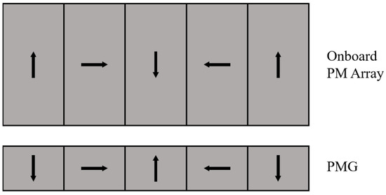
Figure 1.
Schematic diagram of PM array structure of RPML system.
The levitation force of the RPML system at levitation heights ranging from 10 to 50 mm and the lateral force for lateral displacement of ±10 mm at design levitation height of 10 mm are simulated. Figure 2 shows the levitation force and lateral force of the RPML. In Figure 2, it can be seen that the levitation force of the RPML has an exponential relationship with the levitation gap, and the levitation force increases with the decrease in the levitation gap. When the levitation gap is 10 mm from the design operating height, the levitation force is 58,345 N, which is much larger than load requirement. The lateral force is in the same direction as the lateral movement, and the lateral force generated during the lateral movement of the train will pull the train in the direction that makes the lateral movement larger. When the lateral movement is 10 mm, the lateral force is 29,758 N.
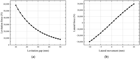
Figure 2.
Electromagnetic force curve of RPML system: (a) levitation force; (b) lateral force.
HTS maglev system also uses the AC/DC module of COMSOL 6.0 for simulation. The HTS maglev system employs the magnetic field formula (mfh) coupled with a moving mesh interface to perform transient electromagnetic force calculations on HTS bulks. In accordance with the preceding research, it was determined that a greater electromagnetic force can be achieved when the lateral size of the HTS bulks is marginally larger than the PMG, and the guideway width is 150 mm. To obtain greater guidance force, three columns of 64 mm × 32 mm × 13 mm HTS bulks are adopted. The configuration of the bulks is illustrated in Figure 3.
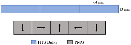
Figure 3.
Schematic diagram of the arrangement of HTS bulks.
HTS bulks’ guidance force above the PMG of RPML was simulated. A lower field cooling height results in a stronger initial magnetic field in the HTS bulks, thereby improving flux pinning effects and enhancing guidance performance. Consequently, the selected working condition maintains identical field cooling height and working height, both fixed at 10 mm. The simulated guidance force curve of 3 bulks is shown in Figure 4. Comparative analysis of the lateral force of PML and HTS maglev shows that, when the lateral movement is 10 mm, the lateral force of PML is 29,758 N per linear meter of the unilateral guideway, and the guidance force of a row of 3 HTS bulk is about 150 N. It requires 200 rows of bulk to balance the lateral deflection force of the PML system. This not only requires excessive space for Dewar arrangement but also loses the significance of the HTS maglev system as a guidance system.
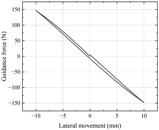
Figure 4.
HTS bulks’ guidance force above the PMG of RPML.
2.2. Hybrid Levitation System Coupling Effects
The hybrid levitation system contains two subsystems: the PML system and HTS maglev system. In this section, the electromagnetic coupling effect between the PML system and the HTS maglev system is studied. A 3D model containing the PMG, on-board PM array, and HTS bulks is built in the finite element software, as shown in Figure 5.
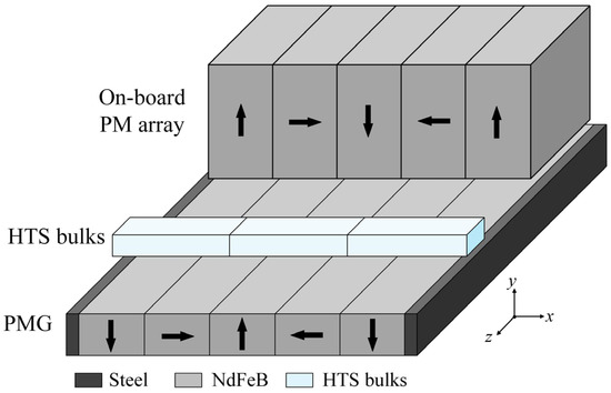
Figure 5.
Schematic diagram of hybrid levitation system simulation model.
In the hybrid levitation system model, the length of the on-board PM array is 50 mm, and the levitation height is 10 mm. HTS bulks’ field cooling height is the same as the working height, which is 10 mm. The setup of the on-board PM array and the HTS bulks and the simulation working conditions are identical to those of the 2D models in Section 2.1. The lateral force for the ±10 mm lateral movement of the on-board PM array and the HTS bulks in the hybrid levitation system are calculated. The lateral forces of PML and HTS maglev in the hybrid levitation system are, respectively, compared with the results calculated from their two-dimensional models in Figure 6.
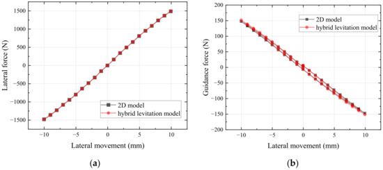
Figure 6.
Comparison of lateral forces between the hybrid suspension model and the 2D model: (a) PML system; (b) HTS maglev system.
Figure 6 shows that the coupling effect between the two subsystems has little influence on the electromagnetic forces. The lateral force of PML is almost unchanged, while the guidance force of the HTS bulks is slightly enhanced due to the magnetic leakage of the on-board PM array. Therefore, it can be seen that the coupling effect of the electromagnetic interaction between the two systems is negligible. It is sufficient to study and optimize the two subsystems separately in the decoupled manner.
2.3. Feasibility Analysis of A-Shape Hybrid Maglev System
2.3.1. PML System
For the A-shape PML system, in the centering position, both sides of the on-board PM arrays are only subjected to the force perpendicular to the lower surface of the arrays upward and the force parallel to the surface. By adding the vectors together, the horizontal component cancels out, and only the vertical component is left, so it can be deduced that the levitation force of the A-shape PML system is slightly smaller than that of flat-laid PML system. When the train undergoes a lateral offset, i.e., when the on-board PM array undergoes a lateral movement, is shown in Figure 7. Here, the movement is assumed to occur to the right. The forces of the on-board PM arrays on both sides are shown in Figure 7.
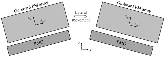
Figure 7.
Forces on the on-board PM array when lateral movement occurs.
As illustrated in Figure 7, the on-board PM arrays experience both perpendicular and parallel force components relative to their bottom surfaces. Specifically, the left and right PM arrays are, respectively, subject to perpendicular forces Flp⊥ and Frp⊥, and parallel forces Flp// and Frp/. Suppose the tilt angle of PM array is α. The levitation force Fpmy and the lateral force Fpmx applied to the on-board PM array can be formulated as
After the overall movement of the on-board PM arrays to the right, the left levitation gap decreases, and the right levitation gap increases. |Flp⊥| is larger than |Frp⊥|; therefore, (−Flp⊥ + Frp⊥) < 0, and both sinα and cosα are smaller than 1. Therefore, A-shape PML system has the possibility of reducing the lateral deflection force.
2.3.2. HTS Maglev System
In the case of the A-shape HTS maglev system, it is noteworthy that the field cooling height is equivalent to the working height. Consequently, there is an absence of electromagnetic interaction between the bulks and the magnetic field when the HTS bulks is in the center position. When there is lateral movement of the bulks, taking the bulks moving horizontally to the right side as an example, the force situation is shown in Figure 8.
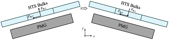
Figure 8.
Forces on the HTS bulks when lateral movement occurs.
As the system is tilted, when the bulks move to the right, the levitation gap on the left side decreases, generating a force Flh⊥ perpendicular to the surface of the bulks upward and force Flh// parallel to the surface to the left. The levitation gap on the right side increases, thus generating a force Frh⊥ perpendicular to the surface of the bulks downward and force Frh// parallel to the surface to the left. Suppose the tilt angle of the system is α. The levitation force Fhtsy and the lateral force Fhtsx of HTS bulks can be formulated as
According to Equation (3), it can be concluded that when the HTS bulks undergo lateral movement above the A-shape guideway, the force perpendicular to the bottom surface of the bulks decomposes into a horizontal component due to the system’s tilt angle. This mechanical property suggests that the A-shape structure has the potential advantage of enhancing the guidance force of the system. However, it should be emphasized that Equation (4) only establishes the force–decomposition relationship. The vertical force direction cannot be directly determined from this formulation. The direction of the vertical force needs to be verified by further simulation calculations.
3. Levitation Characteristics of A-Shape Hybrid Maglev System
3.1. A-Shape Hybrid Maglev System Design
According to the above calculation and analysis, it can be seen that there is a large difference between the lateral force value of the PML system and the HTS maglev system. For the traditional flat-laid maglev system, the guidance force of the HTS maglev system is hard to counteract the lateral deflection force of the PML system. And both the A-shape PML system and the HTS maglev system have the potential to improve their lateral forces. In this paper, an A-shape hybrid maglev design is proposed. The PMG and the on-board PM array on the right side of the system are shown in Figure 9. The tilt angle of the system is set to be α. While keeping the 90° magnetization angle between adjacent magnets in the PM array, an arbitrary magnetization directions angle β between the magnetization direction of the leftmost magnet and the vertical direction is introduced. The effects of different tilt angles and array magnetization directions on the levitation characterization of the A-shape PML system and HTS maglev system are studied. According to the results in Section 2.3, the coupling effect of the PML system and the HTS maglev system has a negligible influence on the respective electromagnetic forces. Therefore, the levitation characteristics of the PML system and the HTS maglev system are studied separately in a decoupled way.
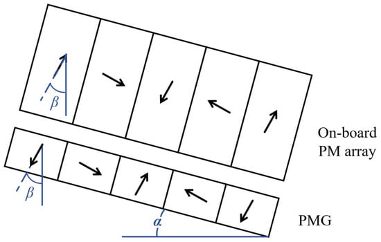
Figure 9.
Schematic diagram of tilt angle α and magnetization direction β.
3.2. The Levitation Characteristics of A-Shape PML System
3.2.1. Effect of Tilt Angle on the Levitation Characteristics of PML System
The tilt angle of the system is set as the variable α for parametric analysis, as shown in Figure 9. When the tilt angle α is changed from 20° to 60°, the levitation force of the system at the levitation height of 10 mm and the lateral force at lateral movement of 5 mm at this levitation height are calculated, as shown in Figure 10.
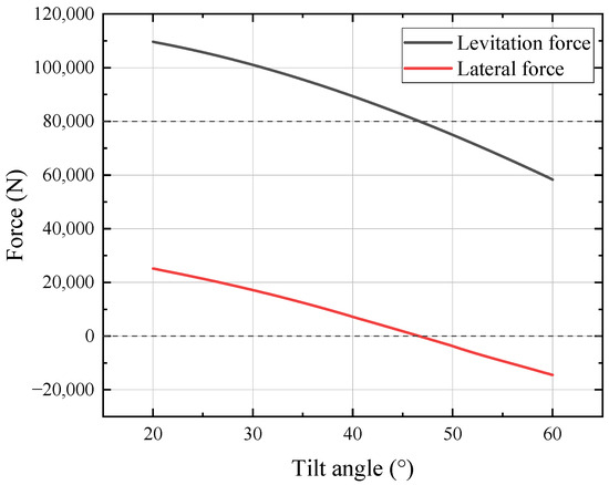
Figure 10.
Variation in levitation force and lateral force with tilt angle α in A-shape PML system.
In Figure 10, it can be seen that with the increase in the tilt angle, both the levitation force and the lateral force show a monotonically decreasing trend. When the tilt angle exceeds 46°, the levitation force decreases to below the rated load requirement of 80,000 N for the bilateral guideway. It is worth noting that, when the angle increases to 47°, the mechanical characteristics of the system undergo a significant transformation, in which the original lateral deflection force is transformed into guidance force. This phenomenon indicates that the system transitioned from passive stabilization to active stabilization at 47°. As can be seen in Figure 8, when the tilt angle α is 46°, the suspension force of the system is 81,033.4 N, which is able to meet the load requirement. And the lateral force at 5 mm lateral movement is 717.1 N, which is 31,582.9 N less than that of the RPML system, and the reduction rate is 97.8%. Notably, when the tilt angle is 46°, a progressive reduction in levitation force is observed as the levitation gap decreases, approaching 10 mm. The levitation force is 81,265 N when the levitation gap is 12 mm, and the levitation force decreases to 81,076 N when the levitation gap decreases to 10 mm. A tilt angle of 45° is found to be a more stable scheme, and the lateral deflection force of this scheme is 1804 N/m, which is 94.4% lower than that of the RPML system.
3.2.2. Effect of Magnetization Direction on Levitation Characteristics of PML System
In the previous study, the magnetization direction of the PM arrays is tilted along with the system. The effect of different angles of the array magnetization direction on the levitation performance of the system is investigated in this section. As shown in Figure 9, the right-side PM arrays are taken as an example. The parametric scanning method is used to simulate the levitation force and lateral force of the PML system when the magnetization direction of the PM array β changes from −20° to 60° while the tilt angle of the system α ranges from 20° to 60°.
Figure 11 illustrates the surfaces of the levitation and lateral forces as a function of the tilt angle and magnetization direction. Among them, the red surface indicates the levitation force, the blue surface indicates the lateral force, the gray surface represents the zero force plane, and the green plane corresponds to the rated load requirement of 80,000 N for the bilateral guideway. It is worth noting that when the lateral force data point is located below the gray reference plane, the system presents the guidance force characteristic, and vice versa for the lateral deflection force. In Figure 11, it can be seen that the mechanical properties of the system show certain regular changes with the changes in PM array parameters. With the increase in tilt angle α and the decrease in magnetization direction β, the levitation force shows a monotonically decreasing trend, and even a reversal from repulsive force to attractive force occurs. The lateral force undergoes a transformation process from lateral deflection force to guidance force. In particular, the intersection parameter space contains optimal angle combinations that achieve the dual objectives of load-capable levitation and self-stabilizing guidance. This parameter range may provide a feasible technical way to solve the problem of negative lateral stiffness inherent in PML systems.
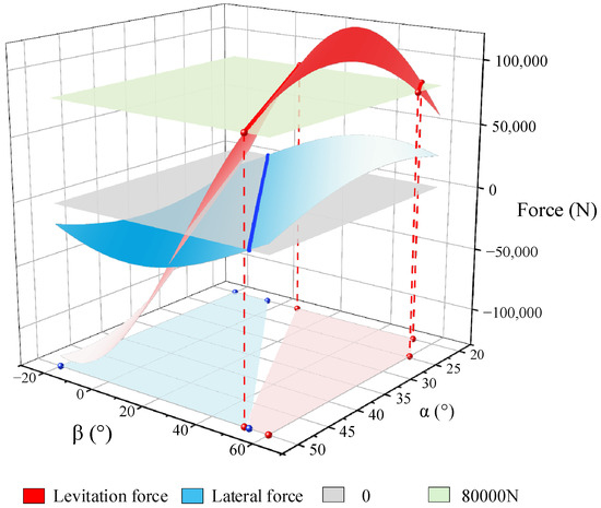
Figure 11.
Variation in levitation and lateral force with tilt angle α and magnetization direction β in A-shape PML system.
Based on the system analysis and image processing results of the simulation data, Figure 12 visualizes the distribution of the angular parameter intervals that satisfy the load requirements of the system and realize the guidance function. The red area in the figure indicates the parameter range that meets the requirement of levitation force, while the blue area corresponds to the feasible interval for realizing the guidance function. Through comparative analysis, it can be found that the overlapping area of parameters (red and blue overlap) that satisfy these two conditions at the same time is very limited. After precise calculation and parameter optimization, the optimal parameter combination of guideway tilt angle α = 50° and magnetization direction β = 52° is finally determined. This optimization scheme effectively solves the lateral stability problem while guaranteeing the load capacity of the system, and it is noted as the 8#1 scheme in subsequent studies.
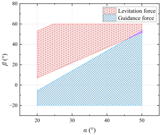
Figure 12.
Optimization interval of levitation and guidance force in A-shape PML system.
The levitation force of the PML system was simulated with the 8#1 scheme at a levitation height of 10~50 mm and lateral force at a lateral displacement of ±5 mm at the levitation height of 10 mm. A comparison of the levitation force and lateral force between the 8#1 scheme and the RPML system is shown in Figure 13. In the figure, it can be seen that in the process of lateral movement, the lateral force of the 8#1 scheme is in the opposite direction of the lateral movement, which realizes the transition from negative stiffness to positive stiffness. However, when the levitation gap is close to 10 mm, the levitation force shows a downward trend with the decrease in the levitation gap. This adversely affects the safety and comfort of the train, so the 8#1 scheme is not feasible.
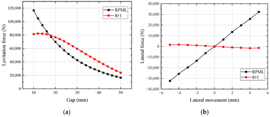
Figure 13.
Comparison of electromagnetic force between 8#1 scheme and RPML: (a) levitation force; (b) lateral force.
As shown in Figure 14, for the optimization interval of levitation force and lateral force of the A-shape PML system, the yellow plane is the benchmark lateral force 32,000 N of the RPML system with lateral displacement of 5 mm. It can be observed that the feasible range of the interval to reduce the lateral deflection force is significantly enlarged. Considering the multivariate variation relationship between the lateral force and the α and the β of the system, the optimized scheme with a tilt angle of 40° and a magnetization direction of 38° is selected, and this scheme is noted as the 8#2 scheme.
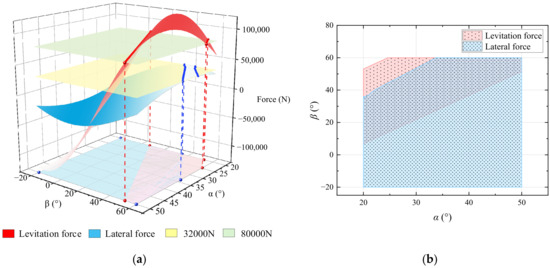
Figure 14.
Optimization interval analysis of A-shape PML system: (a) variation in levitation and lateral force with tilt angle α and magnetization direction β; (b) optimization interval of levitation and lateral force.
The comparison of the levitation force and lateral force between the 8#2 scheme and the RPML system is shown in Figure 15. It can be seen in the figure that the increase in the levitation force of the 8#2 scheme slows down with the decrease in the levitation height, but the overall levitation force still shows an increasing trend. The improvement in the lateral force is also extremely significant: the lateral force at a lateral displacement of 5 mm is reduced from 32,300 N to about 4971 N, a reduction of 84.6%.
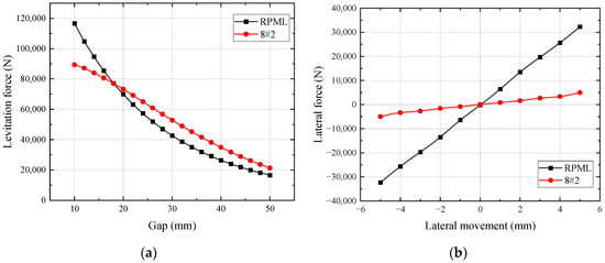
Figure 15.
Comparison of electromagnetic force between 8#2 scheme and RPML: (a) levitation force; (b) lateral force.
3.3. The Levitation Characteristics of A-Shape HTS Maglev System
3.3.1. Effect of Tilt Angle on the Levitation Characteristics of HTS Maglev System
The change in levitation force and guidance force of the HTS bulks in the A-shape system with different tilt angles is simulated. The working condition is 10 mm for field cooling height and working height, and ±5 mm for lateral movement. The calculation results are shown in Figure 16.
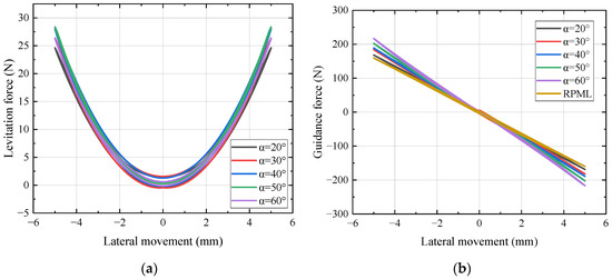
Figure 16.
Variation in the electromagnetic force of the HTS bulks with tilt angle α in A-shape HTS maglev system: (a) levitation force; (b) guidance force.
In Figure 16a, it can be seen that the levitation force of the HTS bulks is always positive during lateral movement, which shows a stable repulsive levitation property. Meanwhile, it can be seen in Figure 16b that the guidance force of the system is positively correlated with the tilt angle of the system, and the guidance force is significantly enhanced as the tilt angle increases. When the inclination angle of the system is increased to 60°, the guidance force is 216 N for a 5 mm lateral movement, which is an increase of 35.8%. Compared to the tilt angle of 20°, the guidance force is increased by 28.6%. There is a certain spatial constraint effect in the A-shape structure. With the increase in the tilt angle, although the guidance performance is improved, the lateral displacement range of the bulks is reduced accordingly. Therefore, an optimal trade-off between the guidance force enhancement and the freedom of movement is needed in practical engineering applications.
3.3.2. Effect of Magnetization Direction on the Levitation Characteristics of HTS Maglev System
In this section, the influence of the magnetization direction of the PM arrays on the guidance characteristics of the HTS maglev system is investigated. Through three-dimensional surface mapping, the guidance force of HTS bulks in the lateral displacement of 5 mm is systematically analyzed when the magnetization direction β of PM arrays changes in the interval of −20° to 120° within the range of system tilt angle α changing from 20° to 60°. The electromagnetic force characteristics under the working conditions of different parameter combinations are quantitatively calculated and analyzed using the finite element simulation method, and the calculation results are shown in Figure 17.
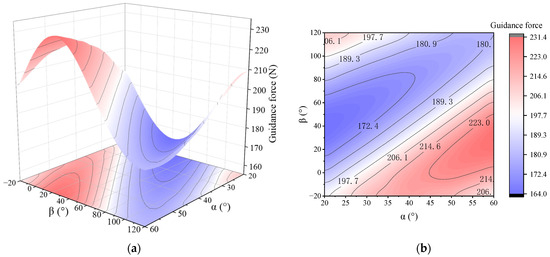
Figure 17.
Variation in guidance force with tilt angle α and magnetization direction β in A-shape HTS maglev system: (a) three-dimensional surface map; (b) contour map.
In Figure 17, it can be seen that the guidance force of the HTS bulks presents complex nonlinear characteristics with the change in the guideway structural parameters. Specifically, with the increase in the tilt angle α and the decrease in magnetization direction β, the guidance force exhibits a multi-polar law of change that increases first, then decreases, and then increases again. Through the parameter optimization analysis, it is found that when the tilt angle α is 60° and the magnetization direction β is 30°, the guidance force reaches a maximum of 231 N. Compared with the flat-laid PMG of the RPML system, the optimized A-shape PMG configuration makes the guidance force of the HTS maglev system increase by 72 N, and the relative increase reaches 45.3%. This is a full proof of the effect of the synergistic optimization of the tilt angle and magnetization direction improving the guidance performance of the HTS maglev system.
4. Conclusions
This paper proposes an A-shape HTS-PM hybrid maglev system. Both the A-shape PML system and the HTS maglev system have the potential to improve the lateral force. And the effects of the tilt angle of the A-shape system and the magnetization direction of the PM array on the key mechanical properties are studied through system simulation calculations so as to provide optimization suggestions.
- When the tilt angle α is 47°, the lateral deflection force of the PML system is transformed into the guidance force, but the levitation force cannot meet the load requirement. The tilt angle α = 45° is the optimal solution, which can satisfy the load requirement, and the lateral deflection force at 5 mm is reduced to 1804 N/m, which is 94.4% less than that of the RPML system.
- When the tilt angle α of the PML system is 49° in conjunction with the magnetization direction β is 52°, the PML system can achieve the guidance property. However, the levitation force of this scheme will increase and then decrease with the reduction in the levitation height, which will have negative impact on the safety of the train operation.
- The optimal solution of the scheme for the synergistic optimization of the tilt angle and magnetization direction of the PML system is α = 40° and β = 38°. The levitation force meets the load requirements. And the lateral deflection force of the system is reduced to 4971 N/m. The reduction is 84.6%.
- For the A-shape HTS maglev system, almost all combinations of tilt angles and magnetization directions of the PM array can improve guidance ability. When the tilt angle is 60° and the magnetization direction is 30°, the lateral force is increased to 231 N, which is 45.3% higher than the RPML.
The lateral force performance of the A-shape levitation systems is significantly improved compared to conventional flat-laid guideway systems. The lateral force of the PML system is significantly reduced, and the guidance force of the HTS maglev system is increased. However, due to the A-shape structure, the lateral displacement of the system is restricted, affecting the train’s ability to negotiate curves. At the same time, optimizing the magnetization direction also increases the difficulty and cost of magnet manufacturing. This study presents a promising solution for developing stable, high-load-capacity hybrid levitation systems.
Author Contributions
Conceptualization, T.X.; methodology, T.X. and L.G.; software, T.X.; validation, L.G.; writing—original draft preparation, T.X.; writing—review and editing, C.P. and P.Y.; project administration, Z.D.; funding acquisition, Z.D. All authors have read and agreed to the published version of the manuscript.
Funding
This work was partially supported by the National Key Research and Development Program of China (2022YFB3505400), the National Natural Science Foundation of China (U24B20125), the Sichuan Science and Technology Program (2025HJRC0003), and the Fundamental Research Funds for the Central Universities of China (2682023CG010).
Data Availability Statement
The data reported in this manuscript are accessible based on reasonable requests to the corresponding author.
Conflicts of Interest
The authors declare no conflicts of interest.
References
- Han, H.; Kim, D. Magnetic Levitation Maglev Technology and Applications; Roess, R.P., Ed.; Springer: New York, NY, USA, 2016; pp. 167–222. [Google Scholar]
- Paden, B.A.; Snyder, S.T.; Paden, B.E.; Ricci, M.R. Modeling and control of an electromagnetic variable valve actuation system. IEEE ASME Trans. Mechatron. 2015, 20, 2654–5665. [Google Scholar] [CrossRef]
- Buth, B.; Lu, B. Dynamic analysis of vehicle-guideway interaction in a maglev cargo transportation system. In Proceedings of the International Mechanical Engineering Congress and Exposition (IMECE), Houston, TX, USA, 9–15 November 2012. [Google Scholar]
- Jung, K.; Shim, K. Noncontact conveyance of conductive plate using omni-directional magnet wheel. Mechatronics 2010, 20, 496–502. [Google Scholar] [CrossRef]
- Fang, J.; Montgomery, D.; Roderick, L. A novel magpipe pipeline transportation system using linear motor drives. Proc. IEEE 2009, 97, 1848–1855. [Google Scholar] [CrossRef]
- Shu, G.; Meisinger, R. State estimation and simulation of the magnetic levitation system of a high-speed maglev train. In Proceedings of the International Conference on Electrical and Mechanical Engineering and Information Technology (EMEIT), Harbin, China, 12–14 August 2011. [Google Scholar]
- Wang, J.; Wang, S.; Zeng, Y.; Huang, H.; Luo, F.; Xu, Z.; Tang, Q.; Lin, G.; Zhang, C.; Ren, Z.; et al. The first man-loading high temperature superconducting maglev test vehicle in the world. Phys. C Supercond. 2003, 378–381, 809–814. [Google Scholar] [CrossRef]
- Deng, Z.; Zhang, W.; Zheng, J.; Ren, Y.; Jiang, D.; Zheng, X.; Zhang, J.; Gao, P.; Lin, Q.; Song, B.; et al. A high-temperature superconducting maglev ring test line developed in Chengdu, China. IEEE Trans. Appl. Supercond. 2016, 26, 3602408. [Google Scholar] [CrossRef]
- Deng, Z.; Li, J.; Zhang, W.; Gou, Y.; Ren, Y.; Zheng, J. High-temperature superconducting magnetic levitation vehicles: Dynamic characteristics while running on a ring test line. IEEE Veh. Technol. Mag. 2017, 12, 95–102. [Google Scholar] [CrossRef]
- Gao, T.; Yang, J.; Jia, L.; Deng, Y.; Zhang, W.; Zhang, Z. Design of New Energy-Efficient Permanent Magnetic Maglev Vehicle Suspension System. IEEE Access 2019, 7, 135917–135932. [Google Scholar] [CrossRef]
- Ohashi, S.; Dodo, D. Levitation and guidance characteristics of permanent magnet-HTSC hybrid magnetic conveyance system. Electr. Eng. Jpn. 2008, 163, 73–79. [Google Scholar] [CrossRef]
- Ohashi, S.; Dodo, D. Influence of the propulsion system on the levitation characteristics of the HTSC-permanent magnet hybrid magnetically levitated system. IEEE Trans. Appl. Supercond. 2007, 17, 2083–2086. [Google Scholar] [CrossRef]
- Ohashi, S.; Nishio, R.; Hashikawa, T. Interaction between propulsion and levitation system in the HTSC-permanent magnet conveyance system. Physica C 2010, 470, 1768–1771. [Google Scholar] [CrossRef]
- Sumida, T.; Kamitani, Y.; Yamada, N.; Ohashi, S. Propulsion characteristics using pinned flux of the HTS in the permanent magnet-HTS hybrid magnetically levitated conveyance system. IEEE Trans. Appl. Supercond. 2016, 26, 3600905. [Google Scholar] [CrossRef]
- Nishio, R.; Ikeda, M.; Sasaki, R.; Ohashi, S. Study on control method of running velocity for the permanent magnet-HTSC hybrid magnetically levitated conveyance system. Physica C 2011, 471, 1492–1496. [Google Scholar] [CrossRef]
- Abdioglu, M.; Ozturk, K.; Gedikli, H.; Ekici, M.; Cansiz, A. Levitation and guidance force efficiencies of bulk YBCO for different permanent magnetic guideways. J. Alloys Compd. 2015, 630, 260–265. [Google Scholar] [CrossRef]
- Abdioglu, M.; Kabaer, M.; Ozturk, K.; Erdem, O.; Celik, S. Lateral position effect of auxiliary permanent magnets on the magnetic force properties of cylindrical YBCO. J. Supercond. Nov. Magn. 2017, 30, 2933–2938. [Google Scholar] [CrossRef]
- Ozturk, K.; Abdioglu, M.; Mollahasanoglu, H. Magnetic Force Performance of Hybrid Multi-surface HTS Maglev System With Auxiliary Onboard PMs. IEEE Trans. Appl. Supercond. 2023, 33, 3600206. [Google Scholar] [CrossRef]
- Zheng, J.; Sun, R.; Li, H.; Zheng, X.; Deng, Z. A Manned Hybrid Maglev Vehicle Applying Permanent Magnetic Levitation (PML) and Superconducting Magnetic Levitation (SML). IEEE Trans. Appl. Supercond. 2020, 30, 3600107. [Google Scholar] [CrossRef]
- Bao, Y.; Zheng, J.; Sun, R.; Deng, Z. Magnetic force characteristics enhancement by a novel permanent magnetic levitation (PML) analysis method for hybrid maglev. J. Magn. Magn. Mater. 2021, 529, 167888. [Google Scholar] [CrossRef]
- Ye, J.; Zhan, P.; Zeng, J.; Kuang, H.; Deng, Y.; Fan, K.; Su, B. Concise magnetic force model for Halbach-type magnet arrays and its application in permanent magnetic guideway optimization. J. Magn. Magn. Mater. 2023, 587, 171301. [Google Scholar] [CrossRef]
Disclaimer/Publisher’s Note: The statements, opinions and data contained in all publications are solely those of the individual author(s) and contributor(s) and not of MDPI and/or the editor(s). MDPI and/or the editor(s) disclaim responsibility for any injury to people or property resulting from any ideas, methods, instructions or products referred to in the content. |
© 2025 by the authors. Licensee MDPI, Basel, Switzerland. This article is an open access article distributed under the terms and conditions of the Creative Commons Attribution (CC BY) license (https://creativecommons.org/licenses/by/4.0/).