1. Introduction
Tendon-driven robots, also known as cable-driven robots or tendon-actuated robots, have garnered significant attention in the field of robotics due to their unique design and potential advantages over conventional joint-driven robots. These robots employ a system of cables or tendons to transmit forces from actuators to the end-effector, enabling a lightweight and compliant structure [
1].
The concept of tendon-driven robots comes from the musculoskeletal system of human beings, where muscles and tendons work in tandem to generate motion and transmit forces [
2]. By mimicking this principle, tendon-driven robots offer several benefits, including reduced inertia, increased power density, and improved dexterity and maneuverability [
3].
One of the key advantages of tendon-driven robots is their ability to decouple the actuators from the end-effector, allowing for remote actuation and a more compact design. This feature enables the placement of bulky actuators at a distance from the end-effector, reducing the overall weight and inertia of the moving parts. Additionally, the compliant nature of the tendons can provide inherent safety features, as they can absorb impacts and reduce the risk of injury in human–robot interactions [
4].
Tendon-driven robots have found applications in various domains, including medical robotics [
5], rehabilitation robotics [
6,
7], and industrial robotics [
8]. Their lightweight and compliant nature makes them well suited to tasks requiring dexterity and safe human–robot interactions.
Tendon-driven actuators are the key components of tendon-driven robots [
9,
10,
11], and modular designs have become increasingly popular in recent years due to their ease of assembly and maintenance. To achieve precise tension control, modular tendon-driven actuators are designed to possess proprioceptive capabilities, which allow them to sense a tendon’s tension and length [
12,
13].
Masayuki Inaba et al. developed a “sensor-driver integrated muscle module” (“SDIMM”), a tendon-driven actuator with proprioceptive capabilities, which served as the foundation for a series of studies on tendon-driven humanoid robots, including the creation of the robots “Kojiro”, “Kenshiro”, and “Kengoro” [
14,
15,
16,
17,
18]. Their actuator employed a motor as the power source, regulating the length of the tendon by driving the motor to rotate the spool, thereby achieving tension control. The actuator also incorporated a load cell, which converted the tendon’s tension into force through a mechanism analogous to a three-pulley system. Although this measurement mechanism enabled tension measurements, it also introduced complexity into the tendon’s motion path, resulting in increased friction loss. The actuator utilized three Hall sensors affixed to the motor end to measure the angle of the motor rotor and subsequently calculated the angle of the spool using the gear ratio of the gearbox. The spool’s angle was then employed to estimate the change in tendon length. However, the resolution of the three Hall sensors was limited to 60°, and the backlash of the gearbox also impacted the accuracy of the angle calculations, which in turn affected the accuracy of the tendon length measurements.
Alois Knoll et al. developed a proprioceptive tendon-driven actuator called the “Anthrob muscle unit” (“AMU”), which was utilized to construct a humanoid robotic arm known as “Anthrob” [
19]. The actuator employed a pair of pulleys to transduce the tension of the tendon into a force on a strain gauge, which was subsequently used to estimate the tension. This tension measurement mechanism bore a resemblance to a three-pulley mechanism and similarly resulted in substantial friction losses. The angle of the spool was then calculated using the gear ratio of the gearbox and used to estimate the change in tendon length. In comparison to Hall sensors, the rotary encoder possessed a higher precision, but its larger size occupied axial space in the actuator, thereby reducing its power density. In this design, the measurement accuracy was also influenced by the backlash of the gearbox.
Haosen Yang et al. designed a tendon-driven actuator called a “magnet-integrated soft actuator“ (“MISA”), which featured a built-in elastic element composed of permanent magnets [
20,
21]. The actuator used an encoder to measure the spool’s angle and estimate the change in the tendon length. However, the absence of a tension sensor meant that the actuator did not possess complete proprioceptive capabilities. The encoder was relatively large in size and occupied a significant portion of the actuator’s axial space, thereby reducing its overall compactness.
Konstantinos Dalamagkidis et al. initiated the MYOROBOTICS project, which involved the development of a tendon-driven actuator called MYO-muscle [
22,
23]. This series elastic actuator features an integrated elastic element, which enables measurement of the tension through the deformation of the elastic component. The actuator utilizes a complex pulley system to convert the tendon tension into the deformation of the integrated elastic element, thereby facilitating tension measurements. Additionally, the integrated motor is equipped with an incremental encoder, allowing for measurement of the spool rotation and subsequent estimation of the change in the tendon length.
Steffen Wittmeier et al. proposed a design for a proprioceptive tendon-driven actuator, and it was used to build three generations of ECCE robots. The actuator had a tension sensor located at the end of the tendon, allowing for direct measurement of the tendon’s tension [
24]. This resulted in a higher measurement accuracy and no additional frictional loss. However, the sensor was not integrated into the actuator, which presented additional design challenges for the robot. Moreover, the actuator also used a potentiometer to measure the spool’s angle, which provided a higher measurement accuracy than calculating the spool’s angle from the motor rotor’s angle. Nevertheless, potentiometers have limitations, including a dead zone and a limited lifespan.
The specifications of the actuators mentioned in the above studies are presented in
Table 1. However, since the ECCE robot project did not disclose detailed information on the actuator used, its specifications are not included in this table.
From the above analysis, it can be seen that in the existing research, tension sensors based on three-pulley mechanisms or external tension sensors are widely adopted. External tension sensors may reduce the integration of the actuator and increase the difficulty of selecting an installation location, which is not a good solution. On the other hand, internal tension sensors typically use a three-pulley mechanism to convert the tension into a force on the load cell, but these pulley groups are often supported by sliding bearings, which can result in significant friction losses due to the complex tendon path and multiple support points. This reduces the transparency of tension transmissions and affects the actuator’s backdrivability.
Existing research has relied on traditional angle sensors, such as encoders, potentiometers, and switch-type Hall sensors, to sense changes in tendon length. However, these sensors have several limitations, including a large size, a short lifespan, and a low resolution, which make them less suitable for this application.
To address the limitations of the existing designs, the authors propose a new tendon-driven actuator design which features a simplified tension measurement mechanism with only one pulley for tendon direction conversion. This design reduces the friction loss and demonstrates good backdrivability. Additionally, the proposed actuator uses a 3D Hall effect sensor to sense the tendon length which is small in size, high in its measurement accuracy, and long in its lifespan. The high integration, compactness, and lightweight design of the proposed actuator result in an extremely high power density, making it an attractive solution for various applications.
The remainder of this paper is organized as follows:
Section 2 describes the design, key parameters, and working principles of the proposed tendon-driven actuator.
Section 3 presents the modeling of the actuator, along with the design of a tension control strategy and a tendon length observer.
Section 4 introduces the design and implementation of the testbench system, as well as performance testing of the actuator, including transient response and tendon length estimation.
Section 5 concludes this paper by summarizing the key findings and outlining potential directions for future research and applications.
2. The Design of the Actuator
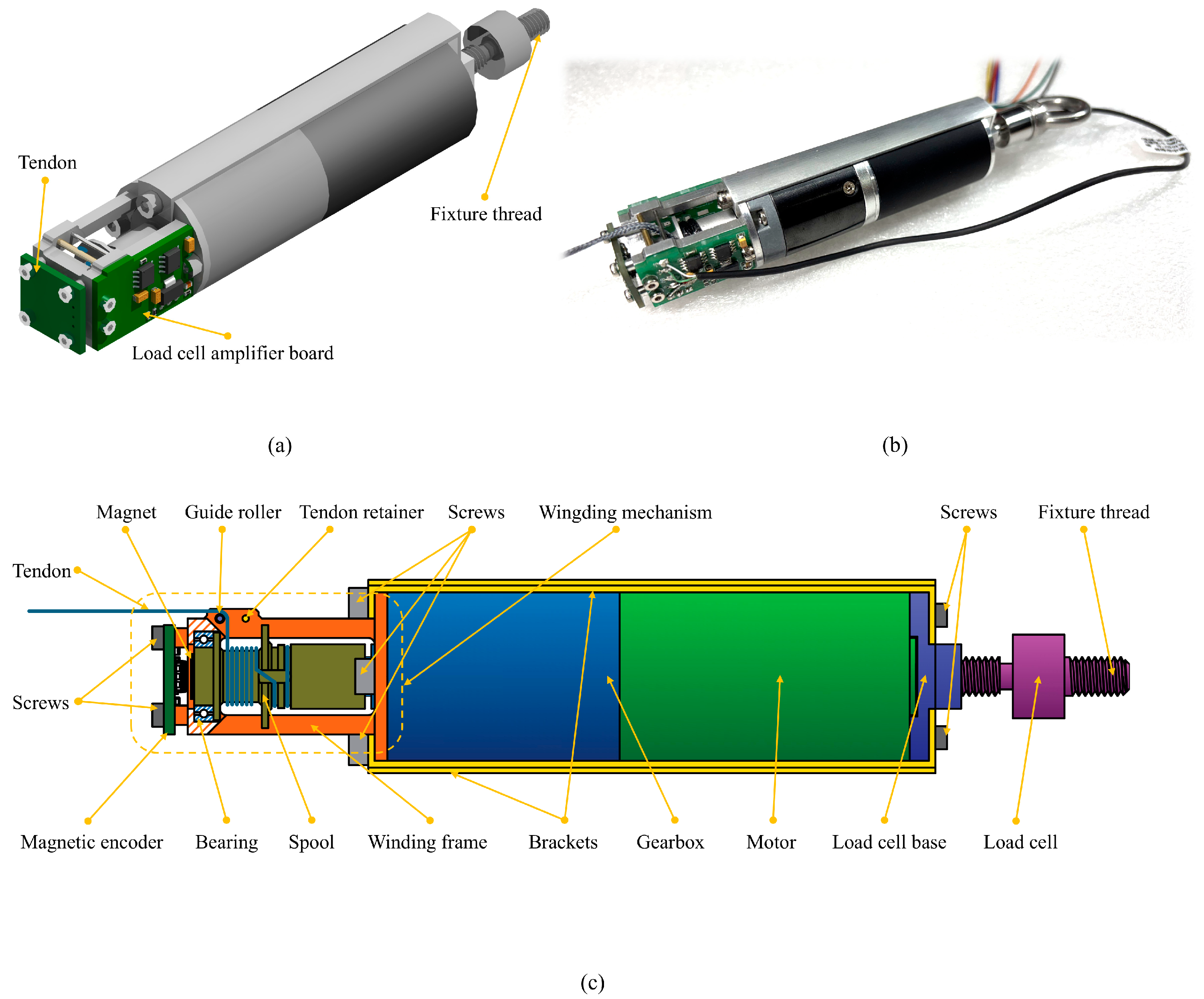
The specification of the proposed actuator is shown in
Table 2, and its design is shown in
Figure 1. The design presented in this paper exhibits a highly compact form factor and a high power density, rendering it more amenable to integration. The attainment of these compact dimensions is attributed to the implementation of a range of novel design strategies.
The actuator’s overall design deviates from the conventional chassis-based architecture, instead opting for a motor-centric design where all of the components are mounted directly onto the motor. The motor is a customized brushless motor, featuring a slotless stator that eliminates the cogging torque, thereby yielding a smooth torque output [
25]. The reducer is a planetary gearbox, distinguished by its simplicity, reliability, and compactness.
The pulley system, comprising a steel shaft and a brass sleeve, is employed to guide the tendon, thereby reducing the frictional force between the tendon and the guiding mechanism and consequently minimizing tendon wear and tear. Furthermore, the adoption of this pulley system configuration enables a reduction in the pulley dimensions, which in turn facilitates the miniaturization of the actuator, thereby enhancing its overall compactness and efficiency.
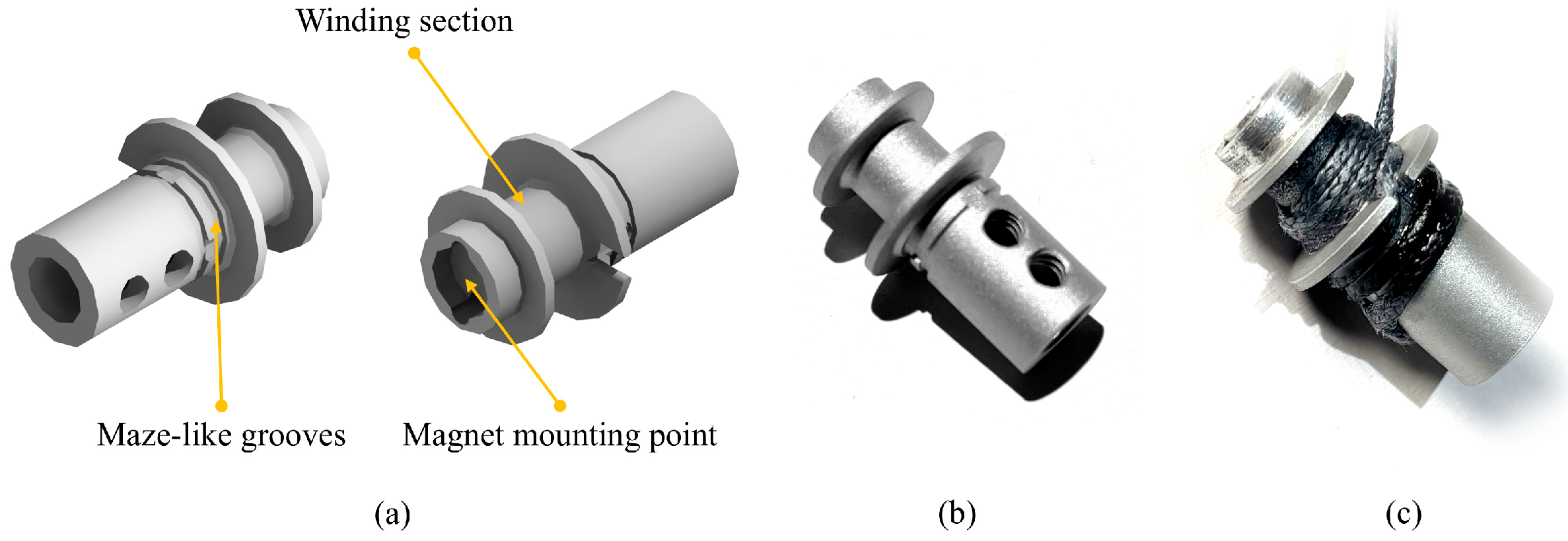
Like the existing research, the proposed actuator also employs a spool to convert the motor’s rotational motion into the change in tendon length. However, existing studies have commonly utilized knotting to secure the tendon to the spool, which raises several issues: (1) the knots occupy additional space; (2) the knots may loosen over time, compromising the actuator’s feedback and control performance and potentially leading to complete failure of the entire tendon-driven system; and (3) stress concentrations occur at the knotting points, increasing the likelihood of tendon rupture and reducing its load-carrying capacity. Some studies have employed bolt-fastening methods to secure the tendon, but this approach is flawed due to the inherently low friction coefficient of the tendon itself. Under a load, the fibers composing the tendon are prone to slipping, ultimately leading to fixation failure. To mitigate this issue, some researchers have adopted the use of multiple bolts to secure the tendon, which, however, increases the spatial occupancy of the fixation mechanism.
To address this issue, this paper presents a novel approach, termed “maze-slot fixation”, to securing the tendon. Firstly, a maze-like pattern of intersecting grooves is machined onto the spool, with rounded corners at the groove intersections. The inner walls of the grooves are then roughened through a sandblasting process. Subsequently, the tendon is placed within the maze slot, and epoxy resin is injected to fix it in place. A magnet is mounted into a recessed slot on the spool and works with a 3D Hall sensor to measure the spool’s rotation angle. The spool and the maze-like grooves are shown in
Figure 2.
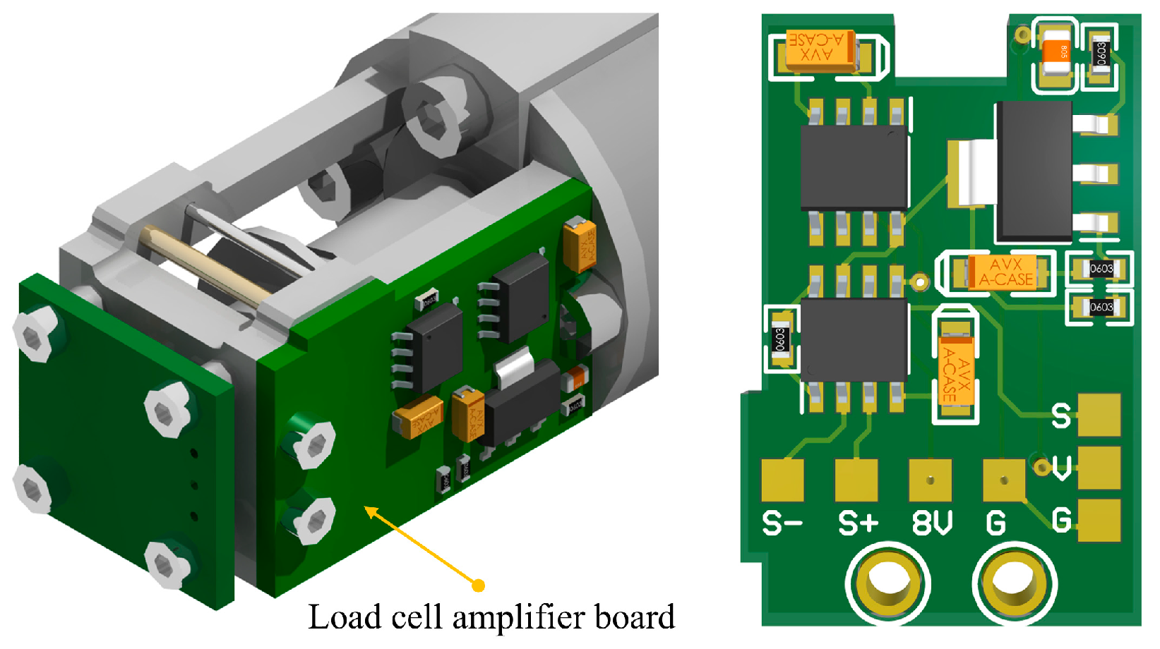
As a proprioceptive actuator, the proposed actuator is equipped with capabilities for tendon length feedback and tendon tension feedback. The tendon tension feedback function is realized through a miniature load cell, which features a diameter of 13 mm, a length of 11 mm, and a weight of 100 g. This load cell operates on the principle of strain measurements and has a bridge-type output structure. The signal amplification circuit of the load cell is directly mounted onto the winding frame, utilizing an instrumentation amplifier as the amplification chip. The PCB (printed circuit board) of the amplifier is shown in
Figure 3.
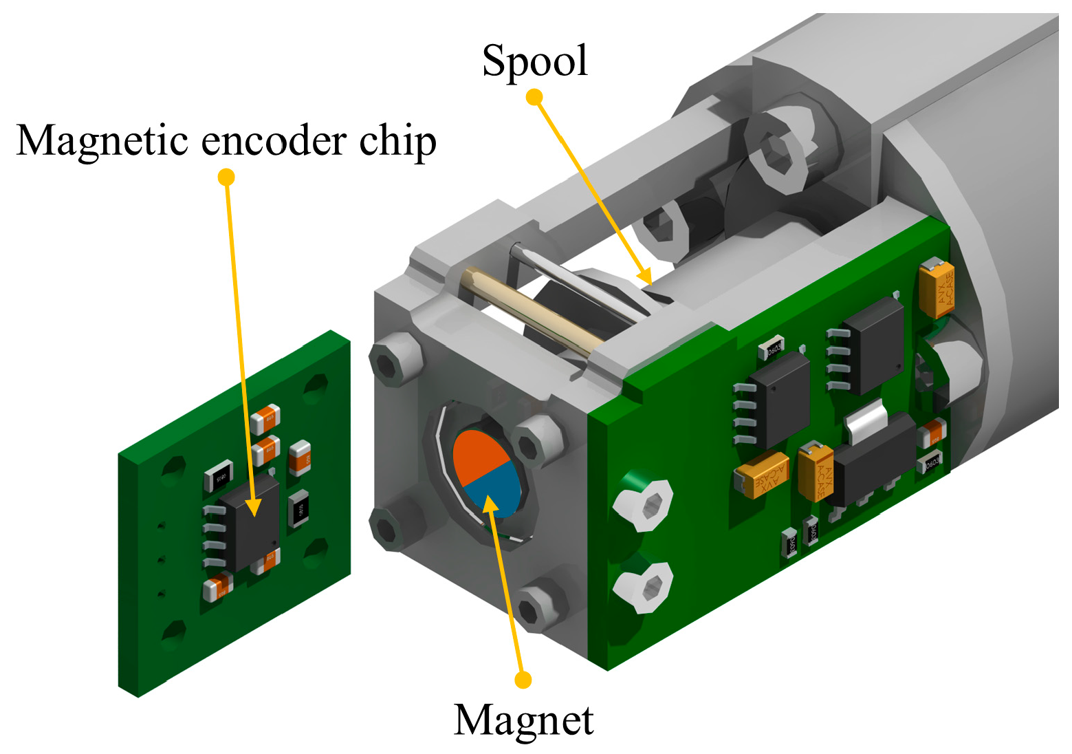
The variation in the length of the tendon cannot be directly measured through sensors and instead can only be estimated through the angular position sensor of the spool and observation algorithms. To minimize the size of the actuator, the proposed design employs a 3D Hall effect sensor to measure the angular changes in the spool. The 3D Hall effect sensor requires a permanent magnet to operate, and the sensor itself has a thickness of only 1.72 mm, which is smaller than the thinnest potentiometer. A permanent magnet can be embedded within the spool, thereby ensuring that it does not compromise the overall size of the sensor. This sensor’s measurement range is limited to 0–360 degrees, equivalent to a single-turn absolute encoder. During actuator operation, the spool will rotate multiple times, and its effective radius will also change gradually with the tendon’s winding, thereby necessitating the use of observation algorithms to estimate the tendon length. The 3D Hall effect sensor and its relative position with the magnet are shown in
Figure 4.
3. Model-Based Controller and Observer Design
Model-based design methods have been widely applied in the development of complex mechatronic systems [
26], and this paper will also adopt this approach to designing the control strategy for the proposed actuator. This section will present the design process for the actuator’s closed-loop tension control strategy and the tendon length observation algorithm.
3.1. System Modeling
In this model, it is assumed that one end of the tendon is connected to a mass of , and the input to the simulation model is the motor current, while the outputs are the tendon tension and length changes.
The motor driver receives current setpoint commands from the tension controller and utilizes its internal inverter to supply the motor with the specified current. The inductive characteristics of the motor’s stator result in a dynamic relationship between the motor’s current and the current setpoint, which can be mathematically represented as
where
is the current of the motor;
is the time constant of the motor’s driving circuit;
is current command sent to the motor driver; and
is the coefficient representing the relationship between the target motor current and the current command.
The motor’s output torque exhibits a linear relationship with the current, with the torque coefficient serving as the proportionality constant, and hence the motor’s output torque is expressed by the following equation:
where
is the output torque of the motor,
is the torque constant, and
is the current of the motor.
The torque causes the motor to rotate, and the motor’s rotational speed can be expressed as
where
is the time,
is the rotational speed of the motor,
is the load torque feedback from the gearbox, and
is the moment of inertia of the motor.
The gearbox’s output torque is reduced due to the frictional losses caused by gear meshing and can be expressed as
where
is the output torque of the gearbox,
is the efficiency coefficient of the gearbox,
is the moment of inertia of the gearbox, and
is the gear ratio of the gearbox.
The gearbox’s output shaft drives the spool to rotate, converting the gearbox’s output torque into tendon tension. This conversion process can be represented as
where
is the tension of the tendon, and
is the radius of the spool.
The load is a spring, with one end connected to the end of the tendon and the other end fixed. Assuming that the spring is initially in a relaxed state, the relationship between the change in the tendon length and the spring force can be expressed as
where
is the stiffness of the spring, and
is the change in the tendon length.
A Simulink model of the system described above was developed to facilitate the design and validation of control strategies.
3.2. The Tension Controller
The proposed actuator is a typical Single-Input Single-Output (SISO) system for tendon tension control. The actuator’s rapid tension response and the built-in tension sensor enable the implementation of a feedback control scheme. However, relying solely on feedback control may not fully exploit the actuator’s capabilities. Fortunately, the availability of the actuator’s dynamic model enables the design of a feedforward tension controller, which can enhance the actuator’s tension response speed by leveraging its inherent dynamics.
Although feedforward control enhances the responsiveness, it is insufficient on its own due to modeling errors, partly attributed to the limited resolution of the motor’s Hall sensors. These errors cannot be eliminated through calibration experiments. Therefore, the tension controller must integrate both feedforward and feedback control capabilities to enhance the control accuracy. To mitigate the impact of steady-state errors on the tension response, this paper employs a feedforward PID (FF-PID) controller as the tendon tension controller.
In each control cycle, the tension controller receives an external tension request, which is then converted into a target motor current using the following method to serve as the feedforward component of the control input:
where
is the feedforward coefficient, and
is the tension request. In the steady-state model of the actuator, the motor’s output torque is directly proportional to the current. Assuming a fixed efficiency for the entire transmission system and neglecting the tendon’s transient characteristics, it can be inferred that the current is proportional to the tendon tension. The tension controller outputs a duty cycle signal for the motor driver, and in the steady-state model, the duty cycle is directly proportional to the motor current. Therefore, the feedforward coefficient can be determined through steady-state experiments.
The feedback portion of the tension controller utilizes a PID control algorithm, which takes the tension error as its input, and can be formulated as follows:
where
is the proportional coefficient,
is the integral coefficient,
is the differential coefficient, and
is the error at the current moment; it can be calculated using the following equation:
where
is the tension feedback at the current moment.
By combining the feedforward and feedback components, a comprehensive representation of the tension controller is established, which can be expressed as
The initial parameter settings of the controller were determined based on a system model identified through simulation data, with consideration of the inertia, elasticity, and friction characteristics of the tendon-driven actuation system. A step response simulation was first conducted to approximate the system as a first-order inertial model, from which an initial estimate of the proportional gain was derived.
Subsequently, an incremental tuning strategy was adopted to refine the PID parameters. For each parameter set, the tension response curve was measured and evaluated in terms of transient characteristics such as the overshoot, rise time, and steady-state error. The final parameter selection achieved a balance between system stability and performance, enabling a fast tension response and low steady-state error.
3.3. The Tendon Length Observer
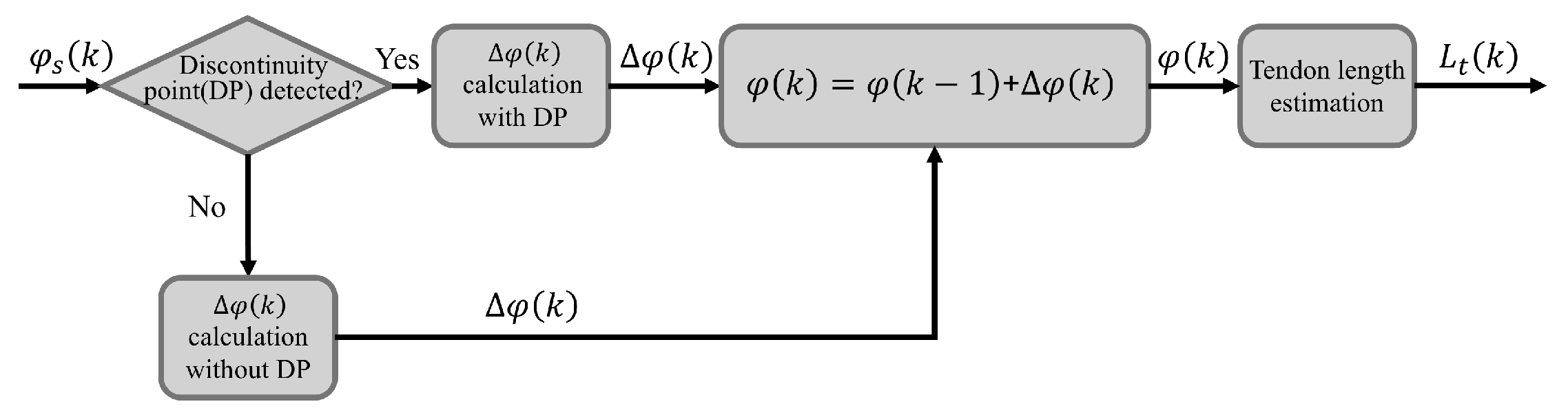
The spool angle sensor is limited to detecting angles within a single revolution (0 to 360 degrees), making it equivalent to a single-turn encoder. However, during actuator operation, the spool may undergo multiple revolutions. Furthermore, measuring the spool angle does not provide a direct measurement of changes in the tendon length. To address this limitation, a tendon length observer is designed to estimate tendon length changes based on the spool angle measurements, enabling accurate monitoring of variations in the tendon length. The working principle of the observer can be illustrated in
Figure 5.
The observer’s input is the spool’s angular position
, with the boundary between 360° and 0° defined as the discontinuity point (DP). When the spool rotates past the DP, the angle sensor’s output exhibits a drastic change, with a slope that exceeds the normal range. This characteristic can be used to determine whether the spool has passed the DP. Based on the current spool angle, the total angle rotated by the spool can be calculated using the following equation:
where
is the cumulative spool angle at the current time step,
is the cumulative spool angle at the previous time step, and
is the single-turn change in the angle measured by the spool position sensor at the current time step. When no DP is detected,
is
When the DP is detected,
is
The length of the tendon is related to the cumulative rotation angle of the spool and its initial length. Compared to the change in length caused by the spool’s rotation, the change in length of the tendon due to external forces can be neglected. Therefore, the length of the tendon
can be estimated using the following equation:
where
is the initial length of the tendon, and
is the radius correction coefficient, which increases linearly with the spool’s rotation angle. As the spool rotation angle increases, the tendon winds around the spool, causing the effective radius of the spool to increase. In this paper, a linear correction coefficient is used, where
increases linearly with the cumulative rotation angle of the spool.
3.4. The Model-in-the-Loop Test
To evaluate the effectiveness of the tension control strategy, the authors conducted a series of closed-loop tests in a simulated environment. Only the closed-loop tension controller was verified in this test, as the tendon length observer would only be meaningful when tested on a real actuator, and the simulation environment could not effectively simulate the random factors that occur during tendon winding. The model parameters used in the test are shown in
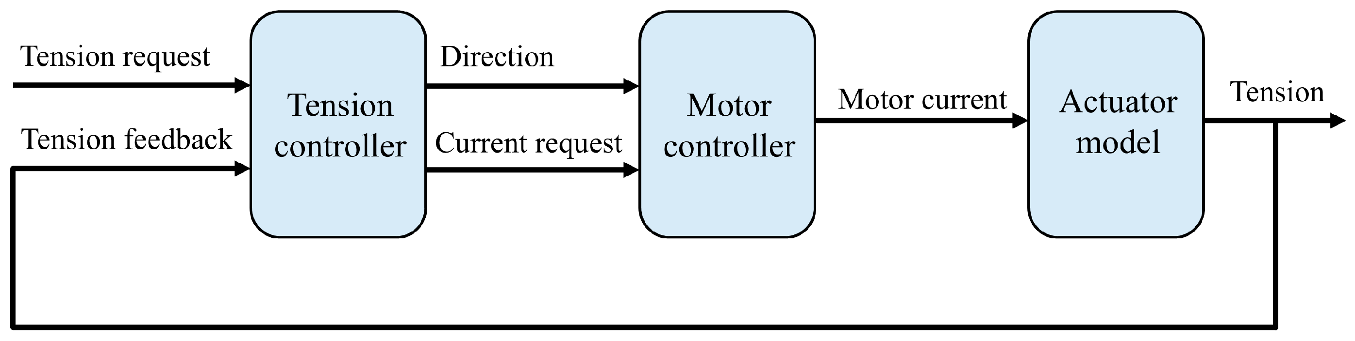
Table 3. The architecture of the simulation model is shown in
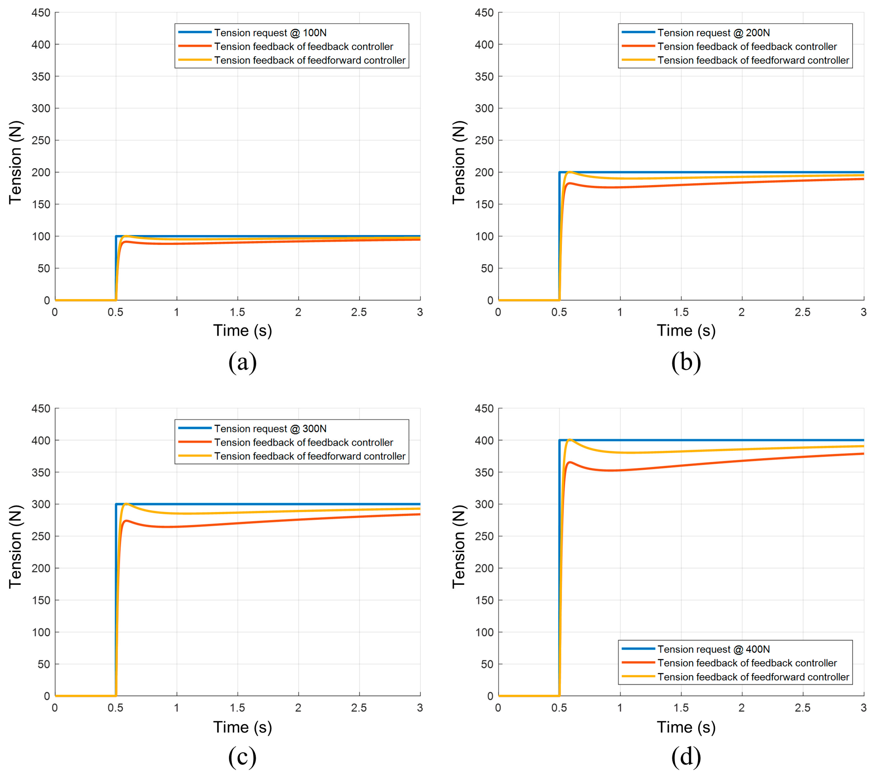
Figure 6. The authors compared the tension control strategy with and without feedforward in this test, and the results are presented in
Figure 7. The feedback control portion of the feedforward controller has the same coefficients as those for the feedback controller.
The simulation results show that the FF-PID controller can effectively achieve closed-loop tension control. Compared to the PID controller, the feedforward PID controller exhibits a faster tension response and a lower steady-state error.
4. Testbench Results and Discussion
In this section, the following verification will be conducted: firstly, the transient response characteristics of the actuator with the closed-loop tension control strategy will be validated through step response experiments, and the results will be analyzed. Subsequently, the accuracy of the tendon length observation algorithm will be tested.
4.1. The Design of the Testbench
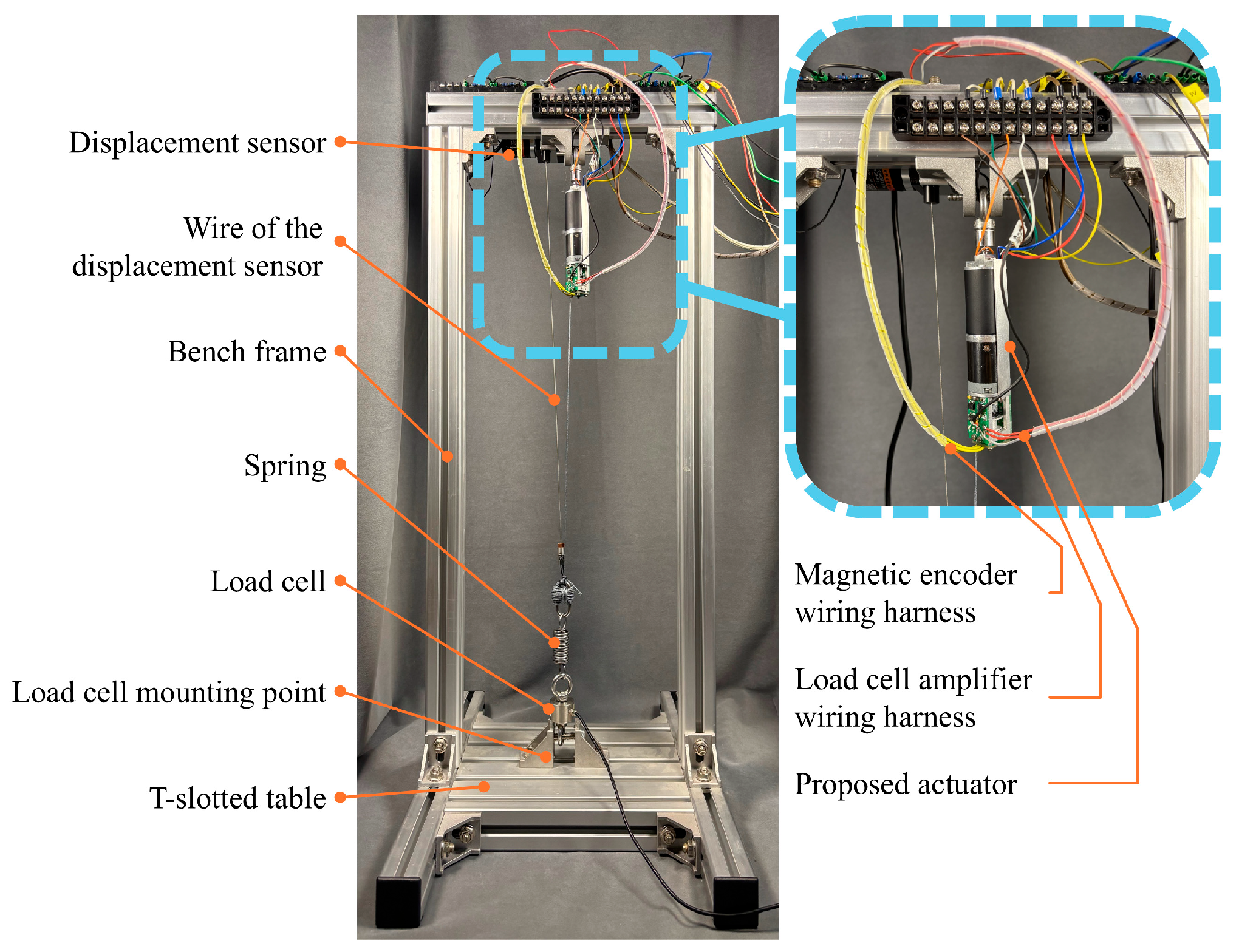
To validate the performance of the actuator, a testbench was set up, as shown in
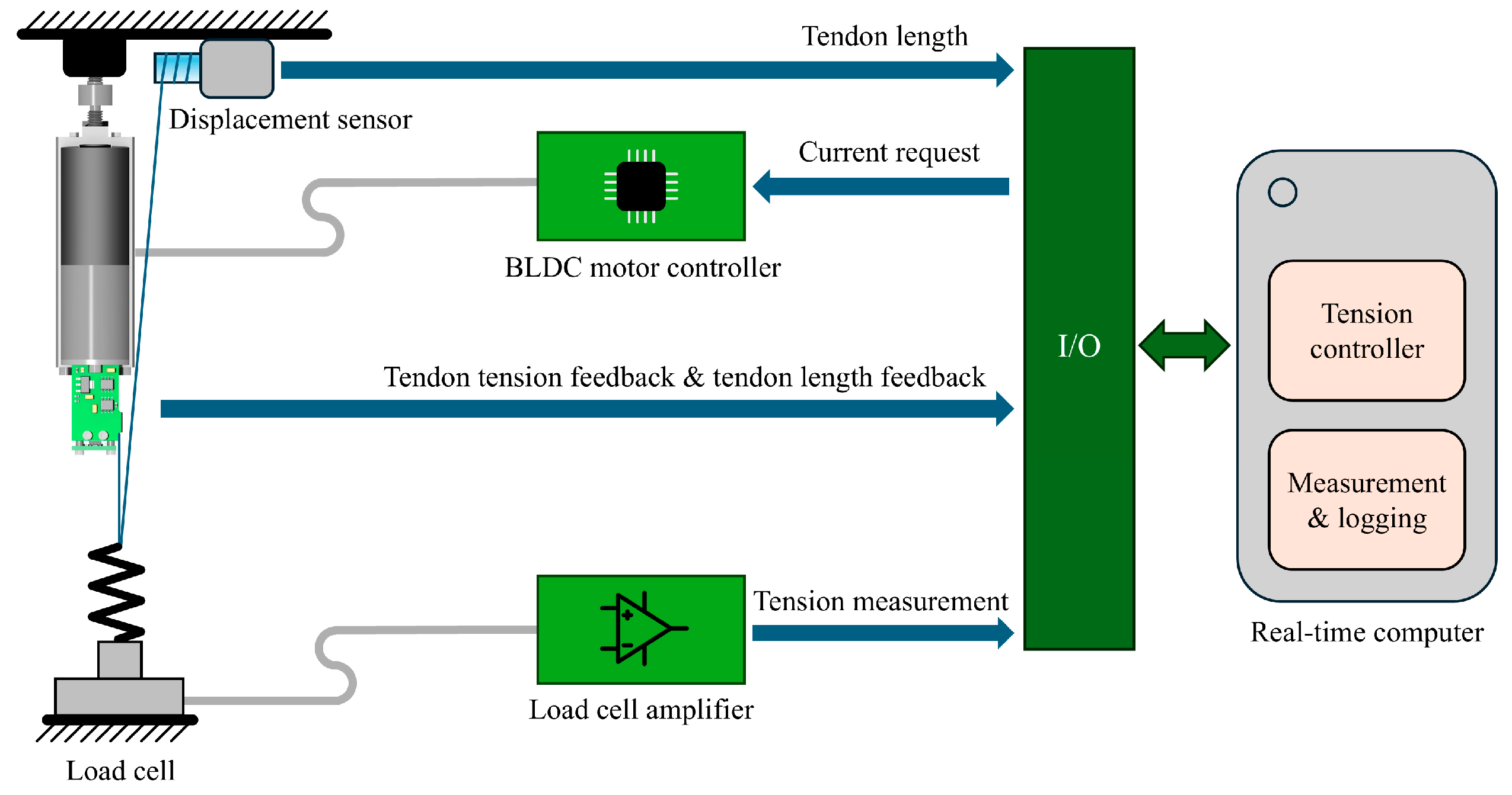
Figure 8, and its architecture is shown in
Figure 9. The testbench consists of a draw-wire displacement sensor to measure the changes in the tendon length and a load cell to measure the tendon tension. These sensors are not utilized as input for the actuator’s tension control but rather serve as a means to evaluate the effectiveness of the actuator’s tension control. The control circuit includes a motor driver to drive the actuator motor, a power supply, and a real-time target machine to run the control algorithm and collect data.
During the testing, the load cell is fixed to the T-slotted table of the testbench. The draw-wire displacement sensor is connected to the end of the tendon, allowing the tendon length changes to be measured. The real-time computer reads signals from the draw-wire displacement sensor, the load cell, and the actuator’s built-in sensors through analog input interfaces and controls the motor driver through digital output interfaces. The motor’s current signal is controlled by a PWM signal, and the motor’s direction of rotation is controlled by a digital output signal. The real-time computer runs the Simulink Real-Time kernel, enabling real-time execution of the Simulink models. The actuator’s tension control strategy and the testbench’s data acquisition logic are both implemented on the real-time computer.
4.2. The Open-Loop Tension Reponse Test
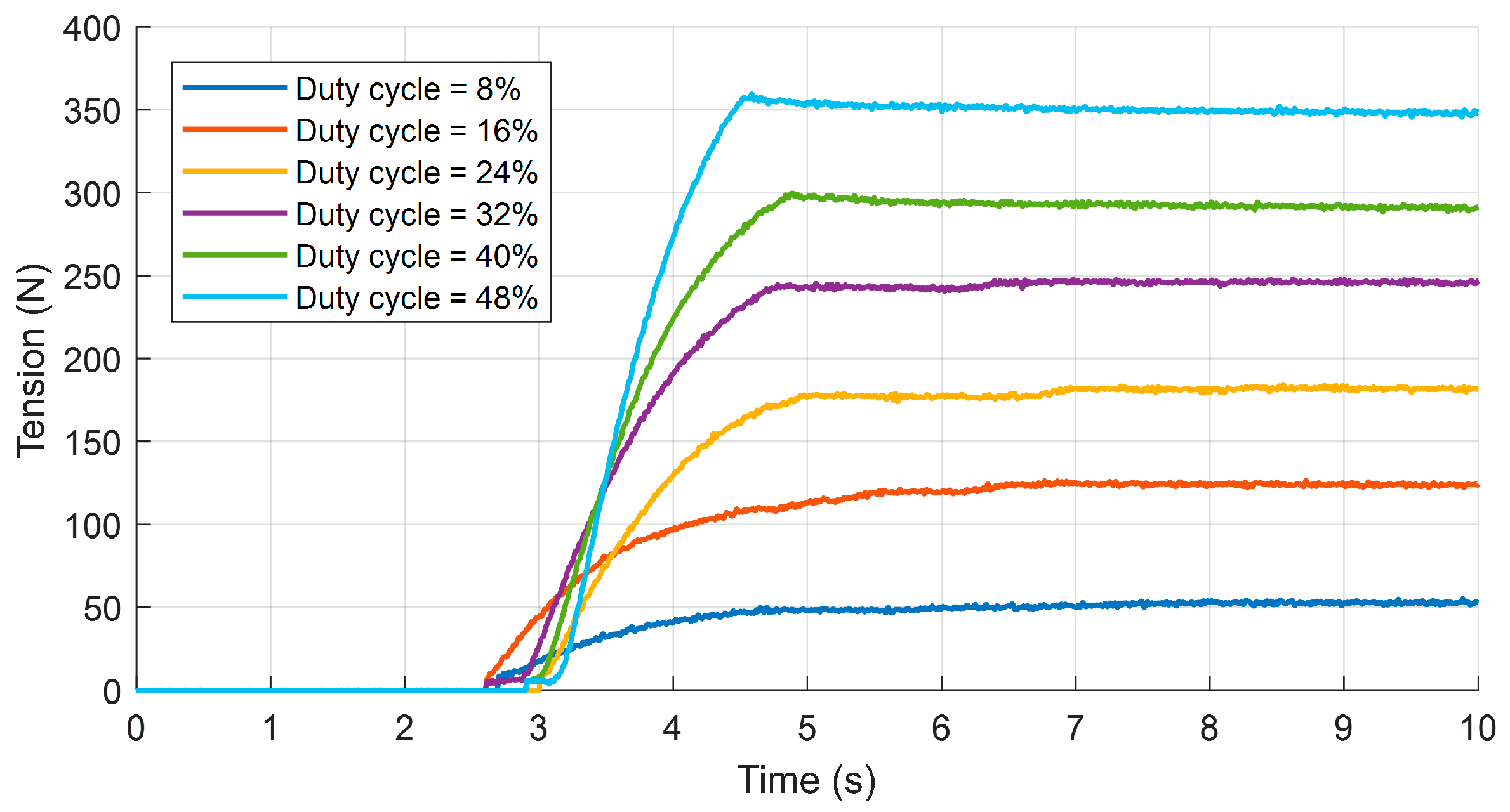
To validate the effectiveness of the closed-loop tension control strategy and compare the performance of the feedback tension controller and the feedforward tension controller, a series of tension step response tests were conducted. First, the authors performed open-loop tension response tests to establish a baseline to compare with the closed-loop control’s performance. During the open-loop testing, the actuator was driven using different duty cycle signals, with the duty cycle ranging from 8% to 48% in increments of 8%. Prior to each test, the tendon was manually adjusted to a non-slack state. In each test, the step time of the step signal was 2.5 s. The results of the open-loop testing are shown in
Figure 10.
The experimental results indicate that the tension response delay varies between 100 ms to 500 ms and does not vary with the duty cycle. The authors infer that the cause of this phenomenon is manual adjustment of the pre-tension state before each experiment, which introduces a significant error into the pre-tensioning process, resulting in a random delay in the tendon’s response to tension.
The open-loop test results demonstrate that the rate of the increase in tension is proportional to the growth of the duty cycle. This phenomenon can easily be explained by the fact that the duty cycle of the drive signal affects the stator current of the motor, and a higher stator current results in a larger output torque, which in turn leads to a faster rate of the increase in tension.
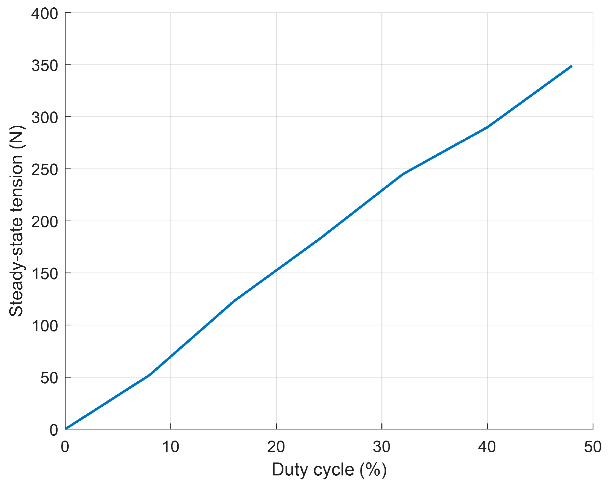
In addition to the rate of the increase in tension, the steady-state tension also increases with the growth of the duty cycle.
Figure 11 illustrates the relationship between the steady-state tension and the duty cycle of the drive signal, revealing a clear proportional relationship between the two. This relationship serves as the basis for determining the feedforward coefficient.
4.3. The PID Tension Controller Test
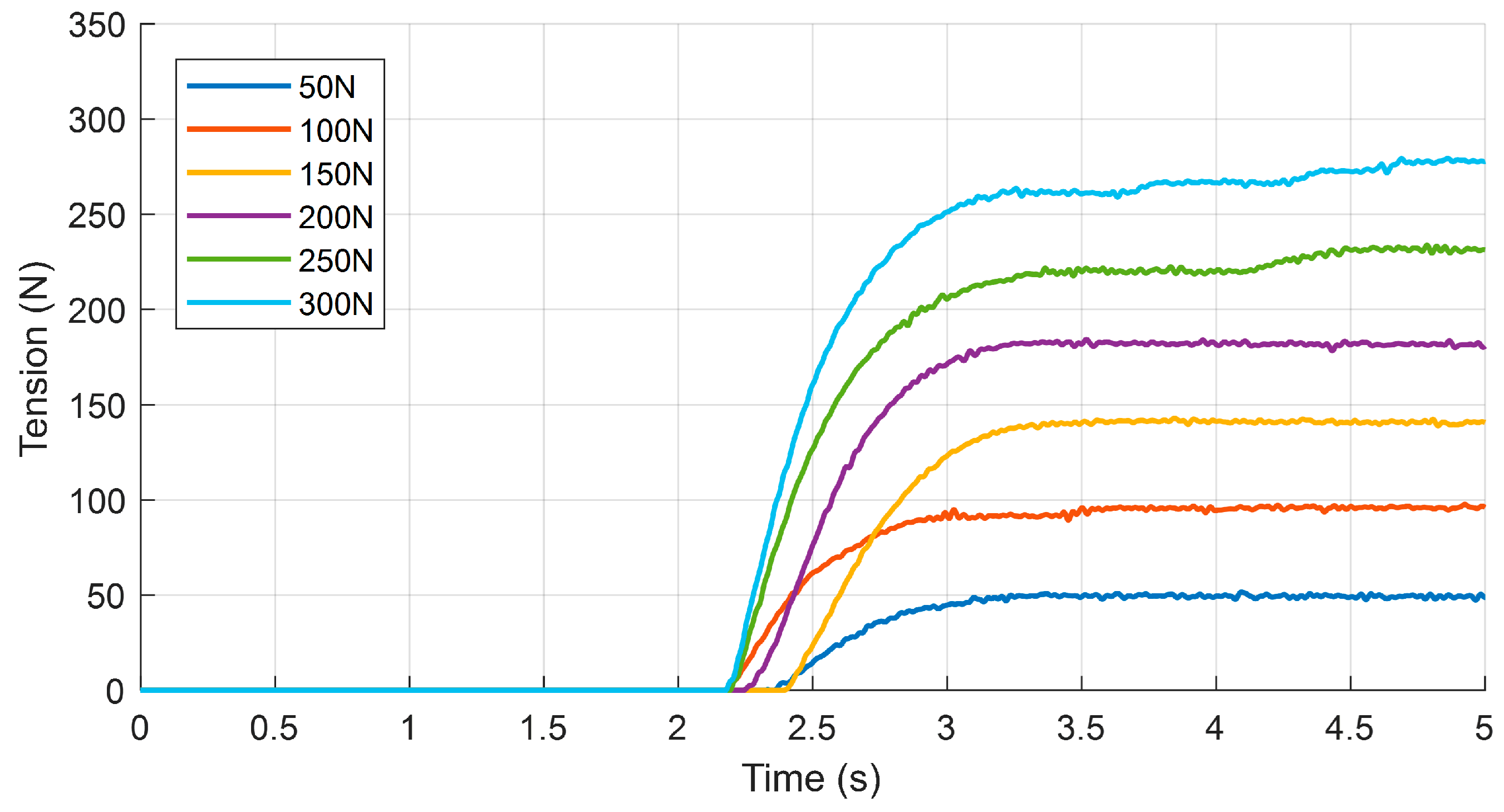
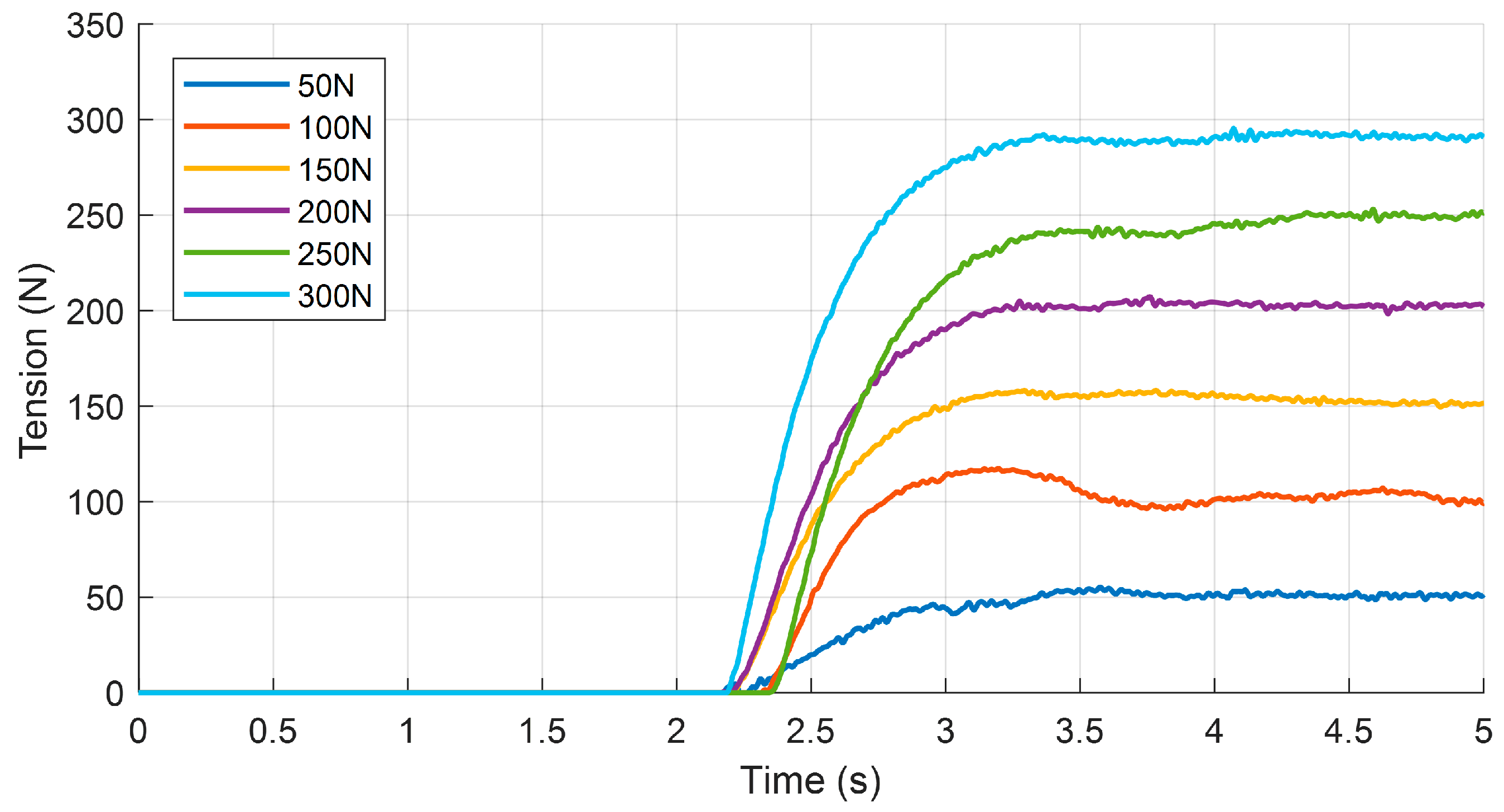
Under low duty cycles, the open-loop control strategy exhibits a slow tension response, which can be effectively improved using the closed-loop tension controller. In this test, the actuator was tested under a series of tension step inputs. The tension requests will range from 50 N to 300 N, with an interval of 50 N. The step time for each tension request is 2 s.
Figure 12 illustrates the actuator’s tension response under PID control.
The PID controller accelerates the tension growth rate, but it is evident that the steady-state error in the tension increases with the growth of the tension setpoint. When the tension setpoint exceeds 200 N, the tension response exhibits distinct characteristics. The authors attribute this phenomenon to the inherent properties of the tendon-driven mechanism, specifically the creep of the tendon under high tension. In this test, the tension response delay still exhibits randomness, and there is no significant difference between the delay observed in this test and that observed in the open-loop test.
4.4. The Feedforward PID Controller Test
To improve the steady-state tension response, a feedforward component was added to the PID controller. The step response results with feedforward PID control are shown in
Figure 13.
As can be seen from the figure, the feedforward controller enables the actuator to achieve a better steady-state tension response, with a reduced steady-state error compared to that with the PID controller.
The authors define the rise time as the time it takes for the tension to increase from 10% to 90% of its steady-state value.
Table 4 lists the rise times of the proposed actuator under PID control and FF-PID control.
As shown in the table above, the proposed actuator under FF-PID control exhibits a reduction in the rise time of 50–150 ms compared to that under PID control. However, at low tension setpoints (e.g., 50 N), the rise time actually increases. The authors attribute this phenomenon to the fact that the difference in the control signal amplitude between FF-PID and PID control is relatively small at low setpoints, resulting in a minimal impact on the rise time. The experimental error is primarily due to random factors.
The authors calculated the steady-state tension by taking the average value of the tension between 4.5 s and 5 s and then comparing it to the tension setpoint to determine the steady-state error.
Table 5 presents the steady-state tension errors for different tension setpoints.
The error analysis results indicate that FF-PID can effectively reduce the steady-state response errors in the tension, but its effect is not significant when the tension setpoint is low (e.g., 50 N). The authors believe that the reason for this phenomenon is similar to that mentioned earlier, namely that the difference in the control output between FF-PID and PID is not significant when the tension setpoint is low.
To validate the effectiveness of the proposed model further, we compared the tendon tension response from the experimental tests with the results obtained from model simulations. The comparison shows that the steady-state tension values in the experiment closely match those predicted by the simulation, indicating the good accuracy of the model in capturing the system’s steady-state behavior. However, the experimental response exhibits a longer rise time than that in the simulated response, indicating a slower buildup of tension in practice.
This discrepancy may be attributed to several factors. First, unmodeled effects such as friction on the tendon routing path and local structural compliance may dampen the dynamic response of the physical system. Second, the tendon may not have been fully taut in the initial phase of motion in the experiments, resulting in a “slack region” dynamic not captured by the idealized model. Third, sensor latency or noise could contribute to the smoother and slower appearance of the rise in the experimental data.
Despite these differences in the dynamic response, the overall trends between the simulation and the experiment are consistent, which supports the validity of the model for capturing the key characteristics of tension behavior. Future work will aim to refine the model by incorporating nonlinear friction and structural elasticity effects.
4.5. The Tendon Length Observer Test
To evaluate the effectiveness of the tendon length observer, the authors conducted a series of tests to estimate the tendon length under various tension conditions. The estimated tendon lengths obtained from the observer were then compared with the measurements obtained from a draw-wire displacement sensor.
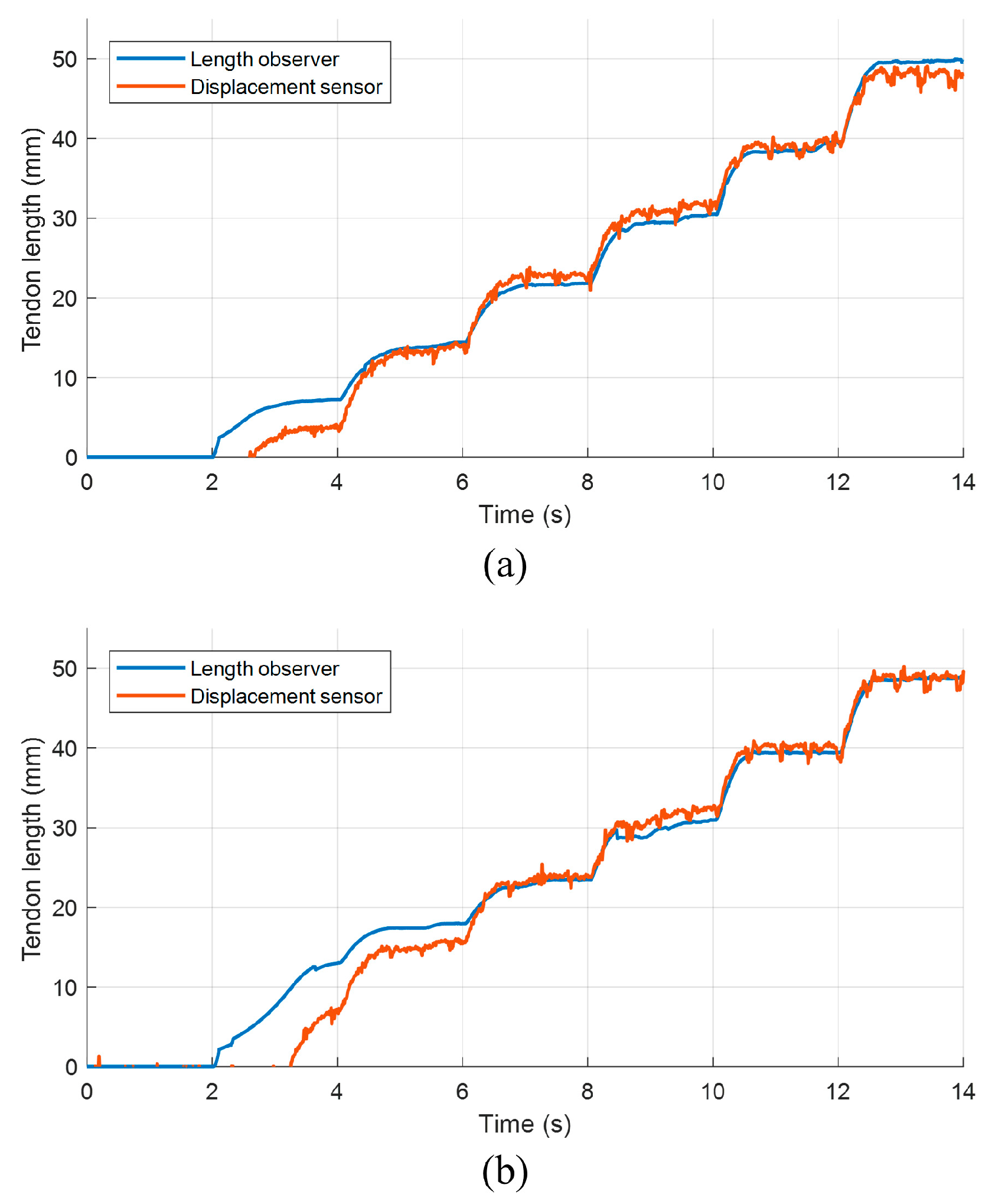
In this test, the tension setpoint was increased in a stepwise manner from 50 N to 300 N, with an interval of 50 N. The results of the observer test are shown in
Figure 14.
From these results, it can be observed that when the tendon length starts to change, the tendon length estimated by the observer is greater than the measurement obtained from the displacement sensor. This discrepancy is particularly noticeable when the change in the tendon length is less than 10 mm.
The authors attribute this phenomenon to the fact that at the beginning of the test, the tendon is not fully taut. As a result, when the spool rotates, it is actually tightening the tendon, rather than driving the load to move. Meanwhile, the displacement sensor’s endpoint is fixed to the load, which means that at the start of the test, the relationship between the tendon’s length and the spool’s rotation angle does not conform to the premise assumptions used to calculate the radius correction coefficient.


