Article

Identification and Compensation of Detection Gain Asymmetry Errors for Hemispherical Resonant Gyroscopes in Whole-Angle Mode

by
Ruizhao Cheng
1,
Gongliu Yang
2,
Qingzhong Cai
1,*,
Xiaodi Yi
1 and
Yongqiang Tu
3
1
School of Instrumentation and Optoelectronic Engineering, Beihang University, Beijing 100191, China
2
School of Mechanical Engineering, Zhejiang University, Hangzhou 310058, China
3
College of Marine Equipment and Mechanical Engineering, Jimei University, Xiamen 361021, China
*
Author to whom correspondence should be addressed.
Actuators 2025, 14(6), 275; https://doi.org/10.3390/act14060275
Submission received: 14 February 2025 / Revised: 24 May 2025 / Accepted: 29 May 2025 / Published: 3 June 2025
(This article belongs to the Section Precision Actuators)

Abstract

Detection gain asymmetry error is one of the primary errors of the hemispherical resonator gyroscope (HRG) in whole-angle (WA) mode. This paper analyzes the influence of detection gain asymmetry error and its coupling error with damping and stiffness asymmetry on the performance of HRG and proposes a novel compensation method for detection gain asymmetry error. Firstly, the nonlinear error model of HRG considering the detection gain asymmetry error and its coupling error is established by using the average method. The influence of the angle-dependent scale factor error (ADS) and angle-dependent bias error (ADB) caused by the detection gain asymmetry error is analyzed by numerical simulation. Secondly, a parameter estimation algorithm based on force-to-rebalance (FTR) mode is proposed to decouple and identify the detection gain asymmetry error and damping asymmetry error. The identified parameters are used for the calibration of the HRG. Finally, the method is applied to the HRG operating in WA mode. The effectiveness of the proposed method is verified by experiments. After compensation, the bias instability is reduced from 3.6°/h to 0.6°/h, the scale factor nonlinearity is reduced from 646.57 ppm to 207.43 ppm, and the maximum pattern angle deviation is reduced from 0.6° to 0.05°.

1. Introduction

A hemispherical resonator gyroscope (HRG) is a type of Coriolis vibrating gyroscope (CVG) that is widely adopted in aerospace, maritime, and land-based applications due to its exceptional precision, reliability, and longevity [1,2,3,4,5]. Compared with other gyroscope technologies such as fiber optic gyroscopes (FOGs), ring laser gyroscopes (RLGs), MEMS gyroscopes, dynamically tuned gyroscopes (DTGs), and nuclear magnetic resonance gyroscopes (NMRGs), HRGs demonstrate superior performance in cost, size, weight, accuracy, and power consumption (C-SWaP).
HRGs typically adopt either a three-piece or two-piece structural configuration. The three-piece structure consists of a hemispherical resonator, a detection electrode base, and a drive electrode base. The resonator is fabricated from fused silica and coated with a conductive layer. Drive electrodes surrounding the equator generate electrostatic excitation forces. Inertial rotation alters the position of standing wave nodes, which is detected by a separate set of detection electrodes. The two-piece configuration simplifies the system by integrating both drive and detection functions into a single planar electrode layer, reducing size and complexity.
There are two modes of operation for HRG. One mode is force-to-rebalance (FTR) mode, which operates HRG as a rate gyroscope by applying a feedback force to make the four-amplitude mode shape overcome the Coriolis force and keep relatively stationary with the shell. In the FTR mode, the inertial rotation angle is calculated based on the applied feedback force. Another mode is the whole-angle (WA) mode, which operates HRG as a rate-integrating gyroscope where the Coriolis force makes the vibration axis process freely. In WA mode, the inertial rotation angle is calculated by measuring the position of the mode shape of the harmonic oscillator. Compared with FTR mode, the WA mode minimizes the energy applied to drive the vibration of the resonator and has a more stable scale factor and higher dynamic range. Thus, owing to the better C-SWaP characteristics and higher reliability, a two-piece-structured HRG in WA mode is the mainstream development of HRG [1,2,3].
The WA mode imposes stringent requirements on the symmetry of the resonator. Manufacturing imperfections inevitably introduce stiffness and damping asymmetries [6,7]. A range of compensation methods have been proposed to address these issues [8,9,10,11,12]. Structural tuning strategies include Choi et al.’s use of the Rayleigh–Ritz method to optimize mass distribution [13] and Gallacher et al.’s electrostatic tuning of stiffness asymmetry [14]. Estimation-based approaches include nonlinear observers [15], normalized least mean square algorithms [16], and Kalman filtering methods such as UKF [17], RLS [18], and EKF [19]. These observer-based techniques often treat fast vibratory signals as state variables, demanding significant computational resources. By contrast, slow time-domain estimation techniques alleviate these constraints, enabling practical implementation.
While these methods address stiffness and damping asymmetries, detection gain asymmetry has emerged as a dominant residual error source. It originates from inconsistencies in electrode–resonator gaps during assembly and mismatch in interface circuit gains. Such asymmetries distort the demodulated signal and degrade pattern angle estimation accuracy.
Previous efforts to mitigate detection gain asymmetry error have focused on isolated treatments. Sun et al. [20] optimized electrode geometry to improve scale factor linearity. Vatanparvar et al. [21] used nonlinear least squares to identify gain mismatches based on angle-dependent bias, requiring high-rate excitation. Fan et al. [22] implemented a virtual rotation-based self-calibration method dependent on stable precession, while Xu et al. [23] employed time-division multiplexing to enable single-channel control and reduce gain-phase mismatches. Despite their benefits, these methods often neglect coupling interactions or require additional excitation mechanisms.
However, there is still a lack of theoretical analysis on the influence of detection gain asymmetry error and its coupling error with damping and stiffness asymmetries. The detection gain asymmetry error causes a scale factor error of HRG changing with the pattern angle. Meanwhile, the coupling error of detection gain asymmetry error and damping asymmetry also causes additional gyro drift. While several methods such as RLS, EKF, and virtual precession calibration have been developed to estimate stiffness or damping-related errors, most of them do not explicitly address the coupling with detection gain asymmetry or rely on real-time filtering with high computational cost.
This paper proposes a model-based strategy that enables offline decoupled identification and compensation of detection gain asymmetry error. The approach extends the averaging framework established by Lynch [24], which characterized frequency and damping asymmetries under ideal detection assumptions. We incorporate detection gain asymmetry error and its interaction with damping asymmetry into a unified nonlinear error model suitable for WA-mode HRG in practical applications.
To address these challenges, the main contributions of this work are summarized as follows:
  • A nonlinear error model of HRG including the detection gain asymmetry error and its coupling error is built by the average method.
  • A comprehensive study of the influence mechanism of the parameter mismatch coupling error is conducted based on the established HRG error equation.
  • A novel identification and compensation method for detection gain asymmetry error is proposed by taking advantage of the fact that the standing wave angle position is fixed when HRG works in FTR mode.
In summary, while the compensation strategy employed is based on conventional modulation and control techniques, the primary contribution of this work lies in the analytical modeling and decoupled identification of detection gain asymmetry and damping asymmetry. By leveraging the non-precessing and stabilized behavior of the FTR mode, the proposed method enables the independent observation and estimation of these two dynamically coupled error sources under WA-mode operation. This decoupling capability is essential for improving the accuracy of parameter identification and has not been systematically addressed in the existing literature.
The remainder of this paper is organized as follows. In Section 2, the theoretical error model of HRG including the detection gain asymmetry error and its coupling error is established and the influence mechanism of the parameter mismatch coupling error is conducted. Section 3 describes the novel identification and compensation method for the detection of the gain asymmetry error. Section 4 contains the description and results of the verification experiments for the proposed method. Section 5 gives the conclusions of the paper.

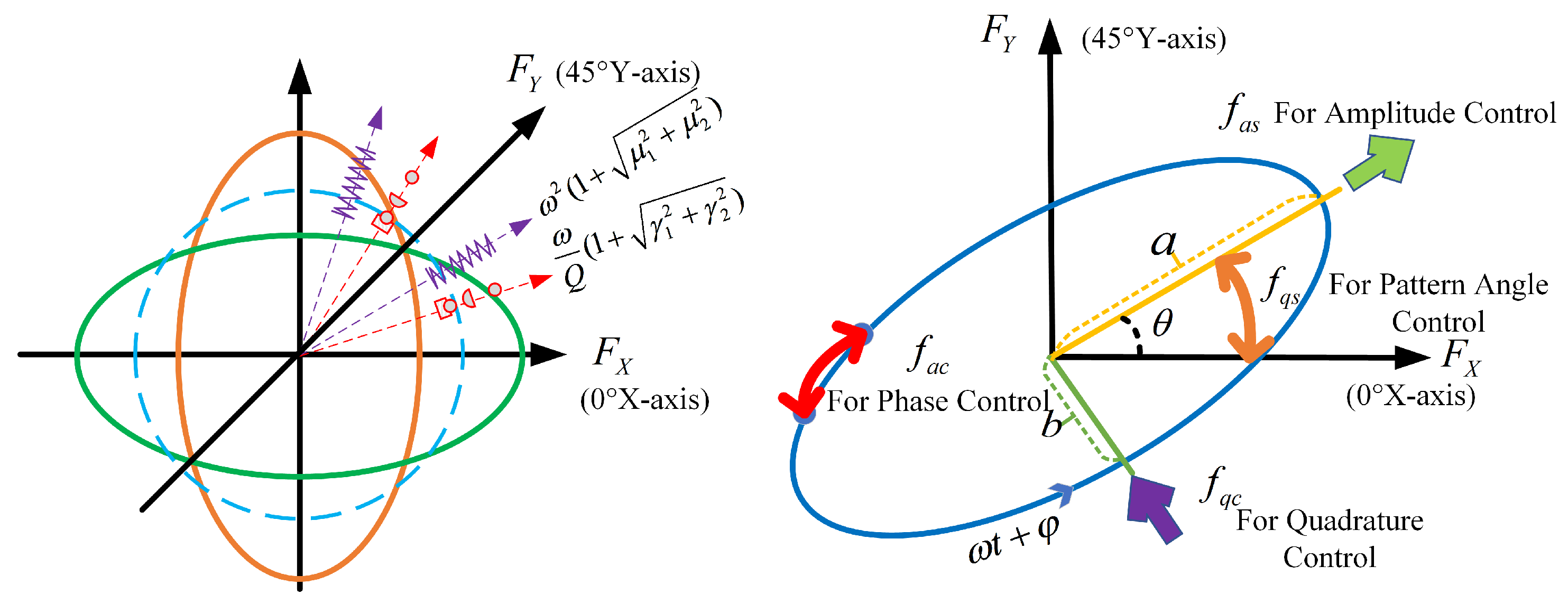
2. Error Model of HRG with Various Parameter Asymmetry

2.1. Equations of Motion

In the ideal case of HRG, the mode amplitudes satisfy linear, second-order equations with coupling terms proportional to the angular rate. The equations are identical in form to those of the two-dimensional linear oscillator. However, structural imperfections always exist in practice. As described in [24], the resonator is characterized by anisotropic damping and stiffness. Thus, the model of HRG must be generalized to include different natural frequencies and damping coefficients of the two modes, and the resonator dynamics are driven by the following relationship.
x ¨ 2 k Ω y ˙ + ω Q ξ ( 1 + γ 1 ) x ˙ + ω Q ξ γ 2 y ˙ + ω 2 ( 1 + μ 1 ) x + ω 2 μ 2 y = F X y ¨ + 2 k Ω x ˙ + ω Q ξ γ 2 x ˙ + ω Q ξ ( 1 γ 1 ) y ˙ + ω 2 μ 2 x + ω 2 ( 1 μ 1 ) y = F Y
where x and y denote the mode displacement of the main resonance axis (x-axis) and quadrature axis (y-axis) separated by 45°, respectively. Ω is the external angular rate. k is the angular scale factor. ω represents the average isotropous resonant frequency of the x-axis and y-axis. Q ξ is the quality factor. Asymmetry errors in damping are denoted by γ 1 in the x-axis and γ 2 in the y-axis. μ 1 and μ 2 represent the stiffness asymmetry error of the x-axis and y-axis. F X and F Y represent the electrostatic force on the x-axis and y-axis, respectively. The angle between the x-axis and y-axis is 45° in physics because the primary and secondary vibration modes intersect at 45°. But the angle between the x-axis and y-axis is 90° in the algorithm to simplify the calculation. Thus, the calculated pattern angle is twice the physical pattern angle as the pattern angle is in a linear relationship.
The general solution of Equation (1) is expressed as the trajectory of a point moving around the origin on an elliptical orbit as shown in Figure 1. a (μm), b (μm), and θ (°) are the vibration amplitude, quadrature amplitude, and pattern angle of the main axis of gyro vibration, respectively. Here, a denotes the amplitude of the standing wave in the primary vibration mode, which is determined by the electrostatic driving force, the mechanical parameters of the resonator (e.g., stiffness and mass), the quality factor Q ξ , and the energy level regulated by the amplitude control loop. φ (°) is the initial phase of the vibration. Hence, the sensed displacements in the x-axis and y-axis can be described as follows.
x ( t ) = a cos θ cos ( ω t + φ ) b sin θ sin ( ω t + φ ) y ( t ) = a sin θ cos ( ω t + φ ) + b cos θ sin ( ω t + φ )
In WA mode, as shown in Figure 1, there are four specific forces to act on the different ellipse parameters separately. The resonator control is built as follows.
F X = cos θ f a s sin θ f q c sin θ f q s + cos θ f a c F Y = sin θ f a s + cos θ f q c + cos θ f q s + sin θ f a c
f a s = A ( θ ) sin φ f q c = B ( θ ) cos φ f q s = P ( θ ) sin φ f a c = H ( θ ) cos φ
where f a s is defined as the control force that maintains the standing wave vibration a. f q c is defined as the control force that suppresses quadrature b. The force f q s is used to alter the pattern angle θ and the force f a c is the frequency control force to change ω . A ( θ ) , B ( θ ) , P ( θ ) , and H ( θ ) are the corresponding angle-dependent controller outputs.
The proposed detection and control system of HRG in WA mode considering the detection gain asymmetry error estimation is illustrated in Figure 2. Eight electrodes were divided into two groups. Electrodes containing Y1, Y2, Y3, and Y4 belong to the first group named as the driving electrodes, which are used to drive the mode’s vibration. Electrodes containing X1, X2, X3, and X4 belong to the second group as the detecting electrodes, which are used to detect the mode’s vibration. The sensing signals of the gyroscope include amplitude a, quadrature b phase error Δ φ , and pattern angle θ . The sensing signals of the gyroscope are amplified by a trans-impedance amplifier (TIA) and are converted into the digital signal by analog to digital converter (ADC). Then, the digital signals are demodulated and combined to obtain the input of the proportional integral (PI) controller. The phase-locked loop (PLL) follows the gyroscope vibration and generates the reference signal. The parameter estimation module is used to estimate the detection gain asymmetry error and the damping asymmetry error. Modulation and damping compensation modules are used to compensate for the damping and generate digital control signals. Quadrature control 1 and quadrature control 2 are used to suppress frequency splitting by means of electrostatic tuning. The control signal mixing module is used to superimpose and mix the control voltage for x and y channels.

2.2. Detection Electrode Errors for HRG

Since the vibration of the lip edge of the resonator is extremely weak, a corresponding weak signal detection scheme needs to be designed for subsequent processing. The detection gain is mainly composed of three aspects as follows.
  • Gain of capacitance changes by the displacement K d c / d s .
  • Gain of the front-end analog amplifier circuit K a m p .
  • ADC and digital signal through the filter digital filter gain K d i g i t a l .
Due to the non-uniformity of the electrode gap caused by the electrode manufacturing process and the difference in the amplifier circuit components in the interface circuit design, the detection gains of the x channel and y channel channels are not completely consistent. Moreover, it is difficult to accurately model the amplification gain of each part. Thus, the detection gain k x of the x channel and detection gain k y of y channel are defined, respectively. Based on the definitions, Equation (2) can be rewritten as Equation (4).
x ^ ( t ) = k x [ a cos θ cos ( ω t + φ ) b sin θ sin ( ω t + φ ) ] y ^ ( t ) = k y [ a sin θ cos ( ω t + φ ) + b cos θ sin ( ω t + φ ) ]
The motion Equations (1)–(4) are derived based on the linear modeling framework of stiffness and damping asymmetries, originally proposed by Lynch [24] and widely adopted in subsequent studies [6] for dynamic analysis of HRG systems. This model uses a first-order approximation to describe the anisotropic decay rates and frequency splitting between the primary and quadrature modes, thereby ensuring analytical tractability and clarity in the formulation. We acknowledge that in real HRG systems, higher-order nonlinear behaviors such as harmonic distortions may arise due to material anisotropy, fabrication defects, or electrostatic tuning effects. However, under moderate vibration amplitudes and operational frequencies, such nonlinearities are typically weak and can be reasonably neglected in system-level modeling. In particular, for the device investigated in this study, detection gain asymmetry has been identified as the dominant source of error, while higher-order nonlinear effects have only limited influence on the pattern angle drift. Building upon the above framework, we extend the model by incorporating detection gain asymmetry and its first-order nonlinear coupling with other system parameters. To preserve modeling clarity and computational feasibility, the formulation is further simplified under the assumption of negligible quadrature error. This modeling strategy retains the essential dynamics required for the proposed decoupled identification method.
By using the averaging method on Equations (1) and (4), the system equations are transformed as slow time-varying elliptical orbit parameter equations defined by Equation (5).
a ˙ = 1 2 k Ω a ( k y k x ) sin 2 θ 1 2 b ω μ 1 sin 2 θ 1 2 b ω μ 2 ( k y sin 2 θ k x cos 2 θ ) a ω 2 Q ξ [ 1 + γ 1 cos 2 θ + 1 2 ( k y + k x ) γ 2 sin 2 θ ] + 1 2 ω A ( θ ) b ˙ = 1 2 k Ω b ( k x k y ) sin 2 θ + 1 2 a ω μ 1 sin 2 θ 1 2 a ω μ 2 ( k y cos 2 θ k x sin 2 θ ) b ω 2 Q ξ [ 1 γ 1 cos 2 θ 1 2 ( k y + k x ) γ 2 sin 2 θ ] + 1 2 ω B ( θ ) θ ˙ = k Ω ( a 2 b 2 ) [ b 2 ( k x cos 2 θ + k y sin 2 θ ) a 2 ( k y cos 2 θ + k x sin 2 θ ) ] + ω 2 ( a 2 b 2 ) Q ξ { ( a 2 + b 2 ) γ 1 sin 2 θ γ 2 [ a 2 ( k y cos 2 θ k x sin 2 θ ) + b 2 ( k x cos 2 θ k y sin 2 θ ) ] } ω a b ( a 2 b 2 ) [ μ 1 cos 2 θ + 1 2 μ 2 ( k y + k x ) sin 2 θ ] + 1 2 ω ( a 2 b 2 ) [ a P ( θ ) b H ( θ ) ]
φ ˙ = k Ω a b ( a 2 b 2 ) ( k y k x ) cos 2 θ + ω ( a 2 + b 2 ) 2 ( a 2 b 2 ) [ μ 1 cos 2 θ + 1 2 μ 2 ( k y + k x ) sin 2 θ ] ω a b ( a 2 b 2 ) Q ξ [ γ 1 sin 2 θ 1 2 γ 2 ( k y + k x ) cos 2 θ ] + ω 1 2 ω ( a 2 b 2 ) [ a H ( θ ) b P ( θ ) ]
where k x and k y are defined as the detection gain asymmetry error as k x = k x k y , k y = k y k x . k x and k y are reciprocal of each other.
As stated above, the factor that specifically affects the characteristics of HRG is not the absolute value of the detection gain but the ratio of the gains of the x channel and y channel. Especially when k x is equal to k y , Equation (5) can be simplified as the differential equation as shown in Equation (6). Equation (5) is the slow time-varying differential equation including the detection gain asymmetry error which is too complicated and can only be analyzed using numerical simulation and is difficult to be applied to the control algorithm for HRG in WA mode. Fortunately, the effective stiffness coefficient of HRG can be altered by an electrostatic field. So a corresponding electrostatic field is generated by applying a direct current (DC) voltage to the excitation electrodes. The electrostatic field also acts on the lip of the resonator to change the resonant frequency to eliminate frequency splitting [25,26,27]. Since the traditional method can reduce the stiffness asymmetry error, the ellipse quadrature parameter b is equal to 0, and the phase error Δ φ is also kept constant by using PLL.
a ˙ = 1 2 k Ω a ( k y k x ) sin 2 θ a ω 2 Q ξ [ 1 + γ 1 cos 2 θ + 1 2 ( k y + k x ) γ 2 sin 2 θ ] + 1 2 ω A ( θ ) b ˙ = 1 2 a ω [ μ 1 sin 2 θ μ 2 ( k y cos 2 θ k x sin 2 θ ) ] + 1 2 ω B ( θ ) θ ˙ = k Ω ( k y cos 2 θ + k x sin 2 θ ) + ω 2 Q ξ [ γ 1 sin 2 θ γ 2 ( k y cos 2 θ k x sin 2 θ ) ] + 1 2 a ω P ( θ ) φ ˙ = ω 2 [ μ 1 cos 2 θ + 1 2 μ 2 ( k y + k x ) sin 2 θ ] + ω 1 2 a ω H ( θ )

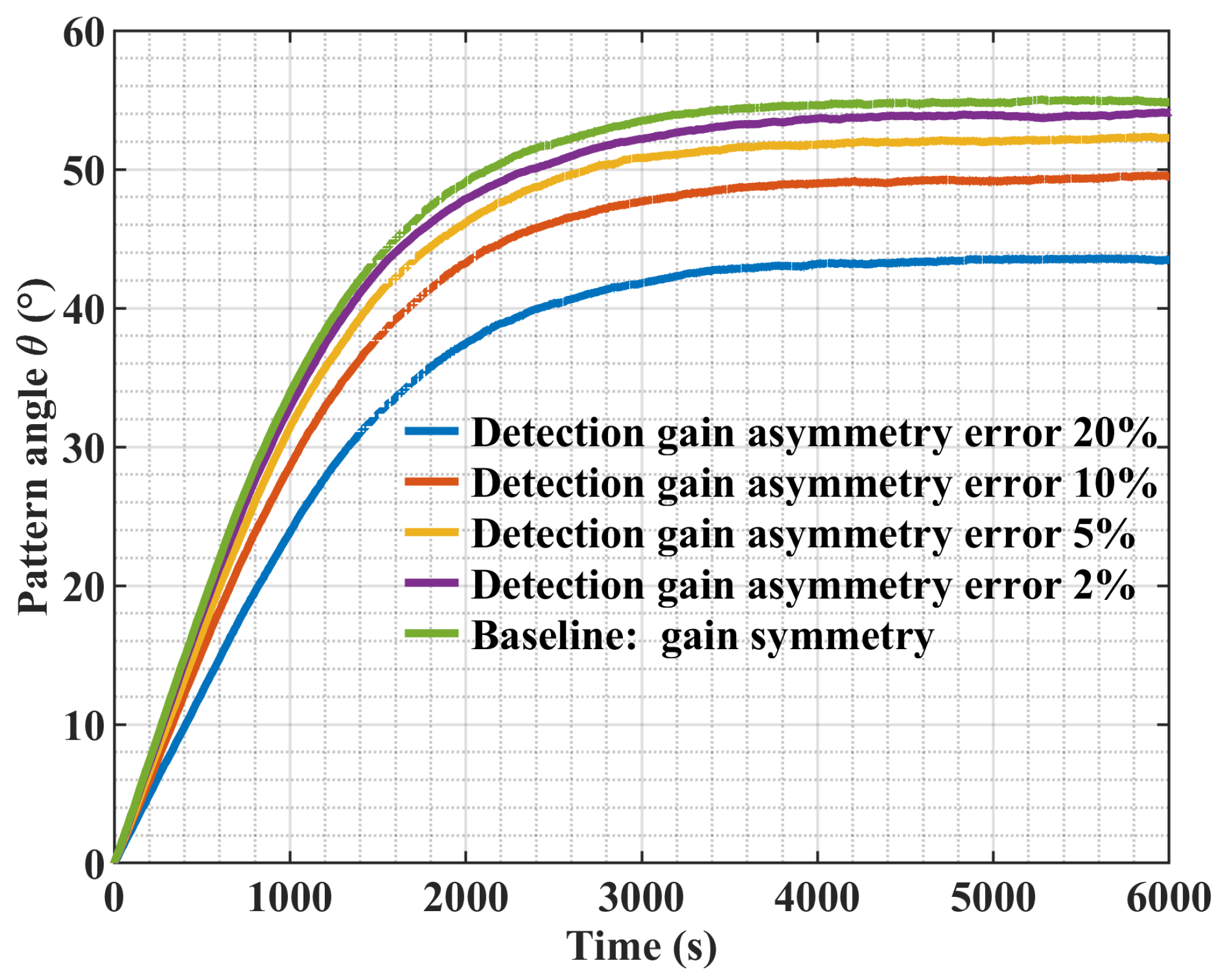
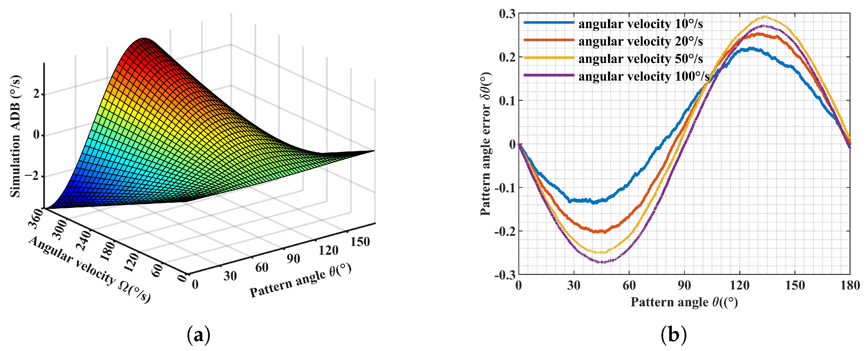
2.3. Numerical Simulation of Detection Gain Asymmetry Error for HRG in WA Mode

In WA mode, the gyro pattern angle continues to precede with the input angular velocity. When asymmetric damping is present, the detection gain asymmetry error not only causes the change in the amplitude control loop but also causes the drift of the pattern angle. In the amplitude or energy control loop, a disturbance damping ratio is proportional to the product of the input angular velocity, and the sine of the pattern angle is equivalently introduced. The influence of detection gain asymmetry error on pattern angle solution is more complex. In WA mode, the standing wave control force f q s is set to 0, i.e., P ( θ ) is 0. Thus, the differential equation about the gyroscope output Equation (6) can be rewritten as follows.
θ ˙ = k Ω ( k y cos 2 θ + k x sin 2 θ ) + ω 2 Q ξ [ γ 1 sin 2 θ γ 2 ( k y cos 2 θ k x sin 2 θ ) ]
Based on Equation (7), numerical analysis is carried out. The detection gain asymmetry error and damping asymmetry error are studied, respectively, and their respective influences on the gyro drift are analyzed. Firstly, the influence of the damping asymmetry error on the gyroscope is reflected in the rate threshold. When the external angular velocity is lower than the rate threshold, the pattern angle will drift to the position of the damping axis and remain stable. In the situation when the detection gain and the damping error are coupled together, although the actual pattern angle will drift to the position of the damping axis, due to the existence of the detection gain asymmetry error, the calculated pattern angle is not the actual damping axis, which affects the correct identification of damping asymmetry errors.
Figure 3 illustrates the simulated drift behavior of the pattern angle θ under various levels of detection gain asymmetry (ranging from 0% to 20%) while maintaining a fixed damping asymmetry of 10%. The simulation is conducted under zero angular velocity input, such that the observed drift is solely driven by internal asymmetry errors. Specifically, the curve for k x = 1 represents the baseline case where the detection gain is symmetric ( k x = k y = 1 ), and the pattern angle drift is only caused by the damping asymmetry. As the gain asymmetry increases, additional drift arises from the coupling effect between detection gain mismatch and damping asymmetry, leading to greater deviation from the damping principal axis. This clearly demonstrates the compound impact of multiple error sources in the WA-mode HRG.
Moreover, Equation (7) can be divided into two parts. One is the coupling error of detection gain asymmetry and damping asymmetry, which introduces external disturbance and causes the pattern angle to drift at different rates according to different positions. Thus, the first part of Equation (7) can be called angle-dependent bias (ADB) in HRG as follows.
δ θ ˙ = ω 2 Q ξ [ γ 1 sin 2 θ γ 2 ( k y cos 2 θ k x sin 2 θ ) ]
On the other hand, the scale factor of HRG is also modulated, which defines the angle-dependent scale factor error (ADS) as follows.
δ k = k ( k y cos 2 θ + k x sin 2 θ 1 )
When the angular velocity is greater than the rate threshold, the standing wave overcomes the rate threshold and continues to process and the ADS and ADB jointly cause the gyro to drift. Figure 4a,b are simulated ADS and simulated ADB under 10% damping error and 10°/s angular rate with different detection gain asymmetry errors.
When there is a detection gain asymmetry error, ADS and ADB vary periodically with the pattern angle. As shown in Figure 4a, when the detection gain asymmetry error increases from the initial value of 1 to 1.1, ADS increases from 0 to 0.003. For the HRG with a precession coefficient k in the value of 0.291, the scale factor nonlinearity will reach 1%. ADB is also affected by the coupling effect of detection gain asymmetry error and damping asymmetry error. Figure 4b indicates that ADB increases with the detection gain asymmetry error. When the detection gain asymmetry error increases from the initial value of 1 to 1.1, the maximum ADB changes from 0.0079°/s to 0.014°/s.
When θ ^ is defined as the calculated pattern angle and k Ω is defined as the actual rotation angle, the pattern angle error can be expressed as δ θ = θ ^ k Ω .
Figure 4c,d express the experimental estimation error of the pattern angle. An HRG that has been compensated for the detection gain asymmetry error is used as the experimental object. Its detection gain asymmetry error is artificially adjusted and tested at a rate of 10°/s. The pattern angle error caused by damping has been compensated by sine curve fitting. Figure 4c is the error of the pattern angle under different detection gain asymmetry errors with the angular rate of 10°/s. Then, HRG with damping asymmetry in values of 5%, 10%, and 20% are selected for tests at a rate of 10°/s. Figure 4d shows the pattern angle error under different damping errors with the angular rate of 10°/s. By comparing Figure 4c,d, when the detection gain asymmetry error increases to 1% and the damping asymmetry error is 10%, the detection gain asymmetry error is the main source of the gyro drift and damping asymmetry error can be neglected.
It can be observed from Equation (7) that when the detection gain error exists, under the common action of ADS and ADB, changes in angular rates also cause changes in the gyro’s drift. Figure 5a is a numerical simulation result under the condition of 10% of detection gain error and 10% damping asymmetric error. The maximum value of the drift is proportional to the input angle rate. When the angular rate is 300°/s, the drift of the gyroscope is 3°/s.
An HRG with a detection gain error of 1% and a damping asymmetry error of about 10% is tested at different rates. Figure 5b shows the estimation error of the pattern angle at different angle rates under the experimental conditions. The greater the input angle rate, the greater the estimation error of the pattern angle. Therefore, it is necessary to compensate for detection gain asymmetry error in high dynamic environments. The identification and compensation of the detection gain asymmetry error is the prerequisite for the normal work of HRG in WA mode.

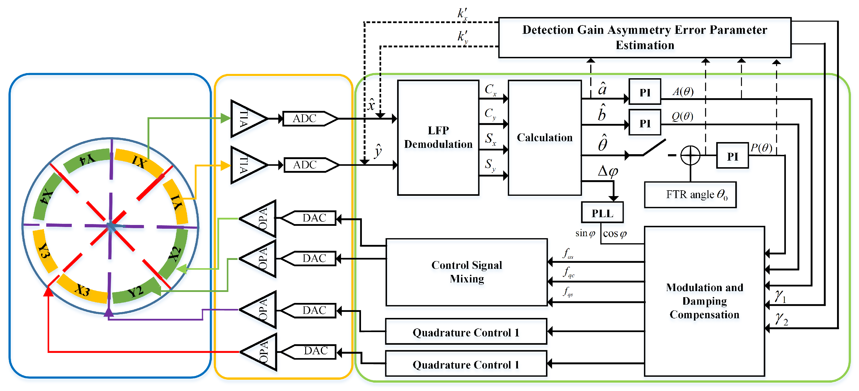
3. Novel Identification and Compensation Method of Detection Gain Asymmetry Error

3.1. FTR-Mode-Based Error Observation and Identification Framework

For a packaged HRG, the detection gain asymmetry error cannot be directly measured. Therefore, the detection gain asymmetry error should be estimated by regarding the output of the gyroscope as the observation. Nevertheless, in the WA mode, due to the coupling error between the detection gain asymmetry error and the damping asymmetry error, Equation (6) is highly nonlinear. The calculated gyro pattern angle θ and vibration amplitude a cannot be directly processed as measured variables. Conventional linear parameter identification methods are difficult to apply. Fortunately, the working characteristics of the FTR mode avoid these problems. The error model of the FTR mode still conforms to Equation (6).
In FTR mode [28], the mode shape of the resonator maintains a non-precession state under the action of the feedback force. Since the pattern angle θ remains unchanged, the damping of the energy control loop by the disturbance of the pattern angle θ is also unchanged. Therefore, traditional proportional integral derivative (PID) control can be used to keep the amplitude a and pattern angle θ as constants. In addition, the coupling error of damping asymmetry error and detection gain asymmetry error will cause additional output in the force balance loop, which is equivalent to angular velocity drift. By observing the gyro output in the FTR mode, the decoupling identification of detection gain asymmetry error and damping asymmetry error becomes possible. At the same time, the parameter identification can be conducted offline to avoid the problem of a large amount of real-time data calculation.
The proposed procedure of the identification and compensation method of detection gain asymmetry error is illustrated in Figure 6. The output data in FTR mode are used to identify the detection gain asymmetry error and damping asymmetry error. The FTR mode control strategy is realized by the traditional method, and the identification process does not affect the normal operation of HRG as shown in Figure 6a. It is important to note that the error parameters identified in the FTR mode—such as the detection gain ratio k x / k y and damping asymmetry coefficients γ 1 , γ 2 —reflect intrinsic structural and interface characteristics of the HRG system. Since the FTR mode and WA mode share the same underlying dynamic equations, with the only difference being whether the pattern angle θ is fixed via the angle control force P ( θ ) , the identified parameters remain valid when transferred across modes. This cross-mode applicability is further supported by the experimental results, where applying FTR-identified parameters in WA mode significantly reduces bias instability and pattern angle deviation under dynamic conditions. These results confirm that the parameters identified under the stable, non-precessing condition of the FTR mode can be reliably used for error compensation in WA-mode operation. Finally, in the WA mode, the identified detection gain asymmetry error is compensated in the two demodulation channels, and the damping asymmetry error in the control loop is also compensated as shown in Figure 6b.
The proposed identification process for detecting gain asymmetry error is described in detail in the following.
Since the amplitude of HRG is constant and the precession angle is fixed in the FTR mode, a ˙ = 0 and θ ˙ = 0 . Thus, Equation (6) can be simplified into Equation (10).
A ( θ ) = 1 2 k Ω a ( k y k x ) sin 2 θ + a ω 2 Q ξ [ 1 + γ 1 cos 2 θ + 1 2 ( k y + k x ) γ 2 sin 2 θ ] 2 a ω P ( θ ) = k Ω ( k y cos 2 θ + k x sin 2 θ ) ω 2 Q ξ [ γ 1 sin 2 θ γ 2 ( k y cos 2 θ k x sin 2 θ ) ] 2 a ω
When the x-axis is used as the drive axis and the y-axis is used as the feedback axis, the value of the pattern angle θ is equal to 0°. Equation (10) can be further simplified as Equation (11).
A ( θ ) | θ = 0 ° = a ω 2 Q ξ ( 1 + γ 1 ) 2 a ω P ( θ ) | θ = 0 ° = k Ω k y ω 2 Q ξ γ 2 k y 2 a ω
When the y-axis is used as the drive axis and the x-axis is used as the feedback axis, the value of pattern angle θ is equal to 90°. Equation (10) can be simplified as Equation (12).
A ( θ ) | θ = 90 ° = a ω 2 Q ξ ( 1 γ 1 ) 2 a ω P ( θ ) | θ = 90 ° = k Ω k x ω 2 Q ξ γ 2 k x 2 a ω
The controller output A ( θ ) , P ( θ ) can be used as observations to estimate the detection gain asymmetry error parameters k x , k y and the damping asymmetry error parameters γ 1 , γ 2 .

3.2. Comparison with Existing Methods

To highlight the advantages of the proposed decoupled identification approach, we compare it with representative prior works, particularly those of Lynch [24] and Vatanparvar [21], which are frequently cited in HRG error modeling and the detection gain calibration literature. Lynch [24] introduced the method of averaging as a foundational framework for analyzing HRG dynamics. His model focuses on frequency and damping asymmetries under the assumption of ideal detection gain. It provides clear analytical insight into structural asymmetries but does not include detection gain mismatch or its coupling with resonator parameters. In contrast, our work extends Lynch’s framework by incorporating detection gain asymmetry into the averaged model and explicitly modeling its interaction with damping asymmetry. This results in a more comprehensive nonlinear error model applicable to practical HRG implementations with non-ideal electronics. Vatanparvar et al. [21], on the other hand, addressed detection and actuation gain mismatches in the control electronics of rate-integrating CVGs. Their method estimates detection gain mismatch via nonlinear fitting of angle-dependent bias (ADB) under high-rate input and estimates actuation mismatch from the output of the energy control loop. While effective for post-calibration, this method assumes minimal mechanical asymmetry and does not consider the coupling effects between gain mismatch and damping. Moreover, it requires specific test conditions with continuous precession, which may limit its applicability in dynamic environments. In contrast to both methods, our approach develops a unified nonlinear error model that includes both gain and damping asymmetries and leverages the fixed pattern angle property of the FTR mode to perform decoupled offline identification. This allows accurate estimation of error parameters without requiring high-rate excitation or continuous closed-loop operation.

4. Experimental Validation and Results

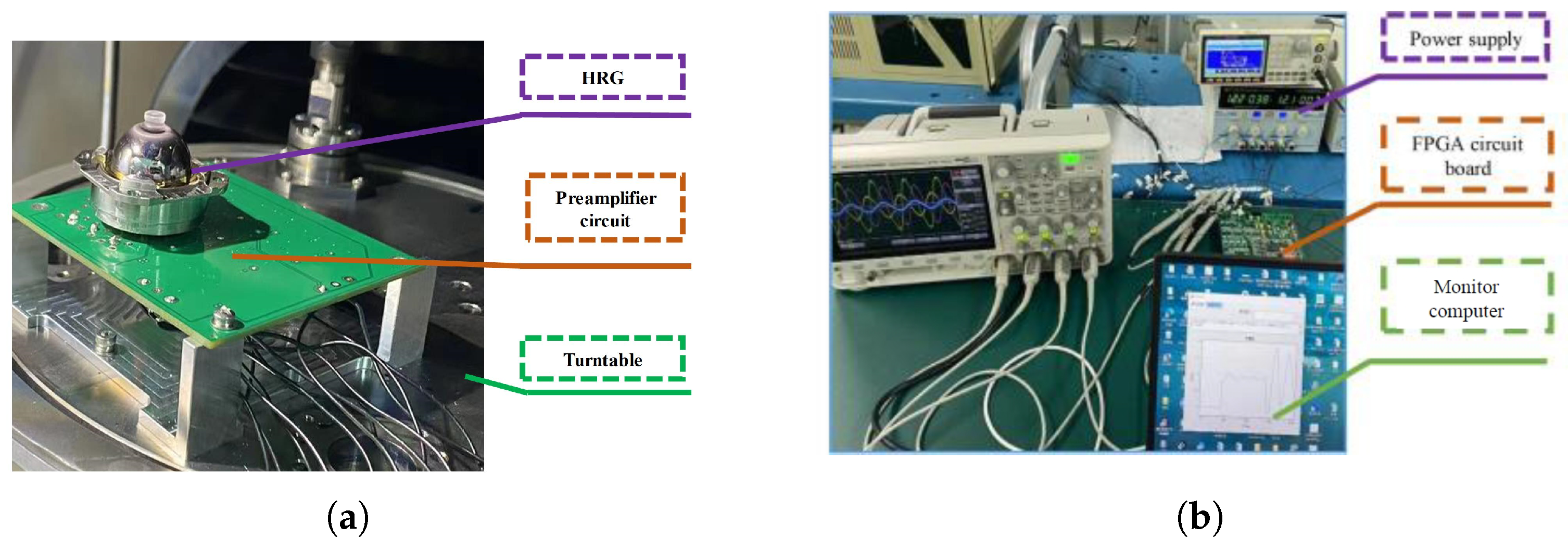
4.1. Experimental Environment

To validate the proposed identification and compensation method, an HRG testing system on a speed turntable was built.
As shown in Figure 7a, the hemispherical resonator gyroscope (HRG) was mounted on the turntable inside a vacuum chamber. Although the chamber was not equipped with active temperature control, the ambient laboratory temperature was maintained within ±1 °C throughout the experiments, which helped suppress temperature-induced variations to a certain extent. The entire setup was installed on a standard passive vibration-isolation platform to reduce the influence of external mechanical disturbances. Figure 7b shows the control circuit and monitor computer system of the HRG. The signal acquisition circuit of the HRG is composed of a TIA and a differential amplifier circuit. The HRG control circuit system is implemented on the ZYNQ platform where the field programmable gate array (FPGA) performs digital multiplier and low-pass filtering on the vibration signal of HRG and then extracts the low-frequency slow-varying information containing the amount of vibration state to the advanced RISC machine (ARM) processor. The corresponding demodulation reference signal can be obtained through the PLL. The slow-varying information was combined in the ARM processor to obtain the corresponding control variable.
The HRG works in the FTR mode, the amplitude variable a, the angular velocity feedback force P ( θ ) , and the amplitude control force A ( θ ) are sent and stored in the monitor computer through the serial port.
Furthermore, since the compensation is applied externally and does not modify the dynamic structure of the control system, it does not introduce high-frequency noise or bandwidth degradation. This ensures that the high-frequency tracking performance of the gyroscope remains unaffected. The proposed method is thus well suited for systems with strict requirements on frequency response and signal-to-noise ratio.

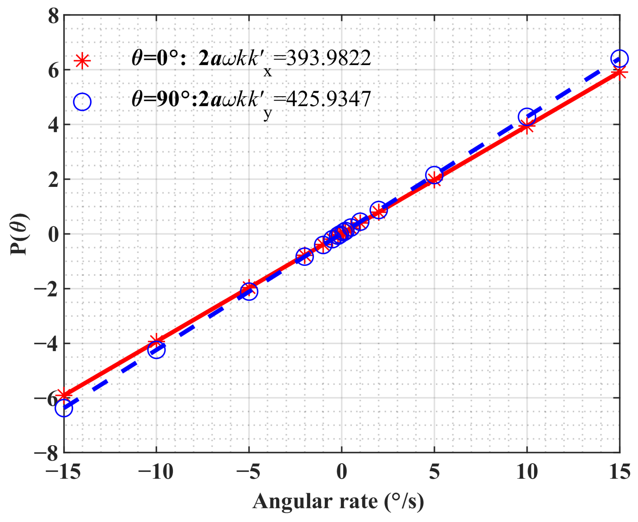
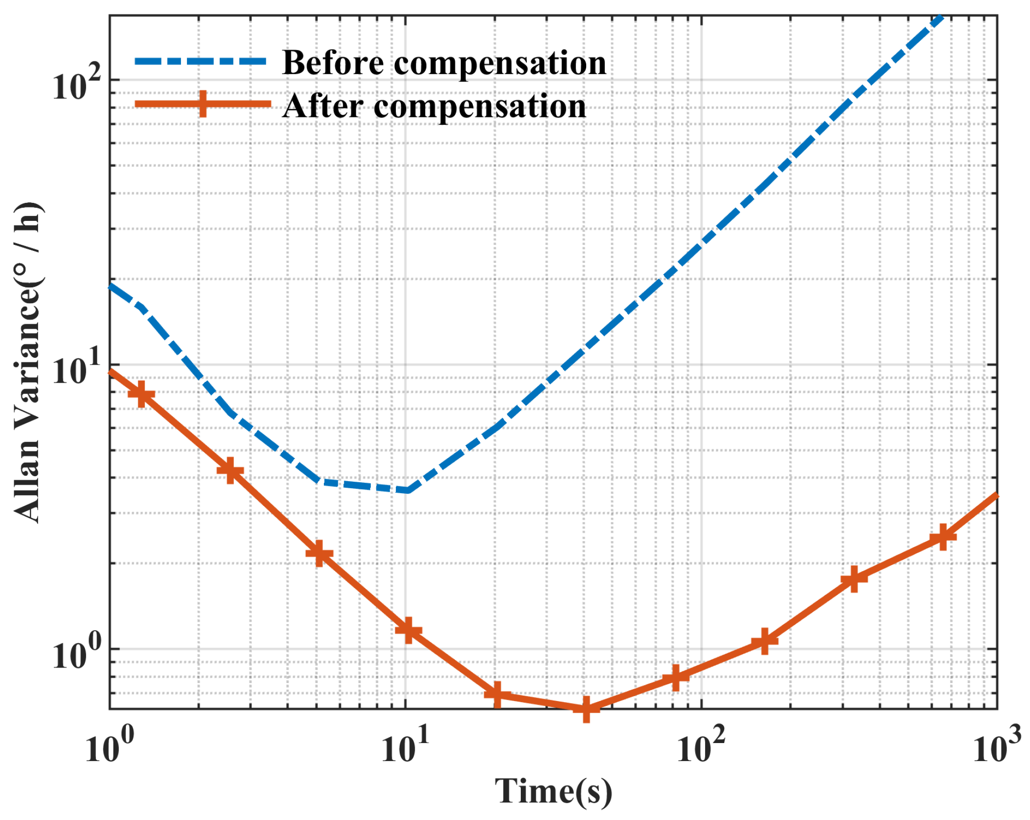
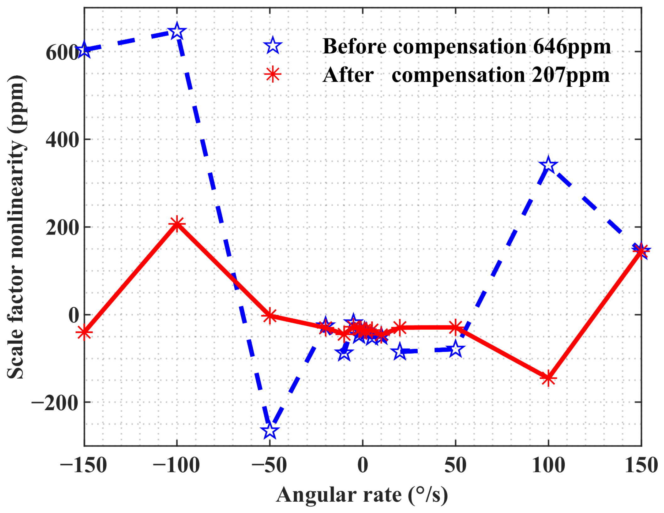
4.2. Experimental Verification and Results

In the identification process of the experimental validation, the HRG operated in FTR mode with pattern angles of 0° and 90°, respectively. Due to the limited dynamic range of the HRG in FTR mode, the detecting gain asymmetry error was calibrated within the rate range of ±15°/s. The HRG worked for 10 min each time and the output of the controller was collected and stored using the monitor computer. The output of the controller is the digitized result without actual units. The average value was calculated as the measurement result. The identified results are shown in Figure 8 as detection gain asymmetry error are k x = 0.9618 and k y = 1.0398 .
The identified detection gain asymmetry error is compensated to the detection channel, and adjust the gains of the x channel and y channel are adjusted to make them consistent as shown in Figure 2. The damping asymmetry error is compensated by the self-precession method proposed in [29].
After the compensation of the detection gain asymmetry error and damping asymmetry error, as shown in Figure 9, the Allan variance showed that the bias instability of HRG decreases from 3.6°/h to 0.6°/h after compensation. Compensated HRGs were tested at ±0.1°/s, ±0.2°/s, ±0.5°/s, ±1°/s, ±2°/s, ±5°/s, ±10°/s, ±20°/s, ±50°/s, ±100°/s, and ±150°/s and output rates were linearly fitted to calculate the nonlinearity of the scale factor as shown in Figure 10. The scale factor nonlinearity is reduced from 646.57 ppm to 207.43 ppm after compensation. As shown in Figure 11, the output performance of the HRG is compared under the dynamic angular velocity input of 50°/s. The result shows that the maximum pattern angle error of the compensated gyro is reduced from 0.6° to 0.05°, which is reduced by 91.6%.

5. Conclusions

In this paper, a nonlinear error model of the HRG in WA mode including the detection gain asymmetry error in the WA mode is derived. The ADS and ADB caused by the detection gain asymmetry error are analyzed. Based on the analyses, a novel identification and compensation method of detection gain asymmetry error for HRG in WA mode is proposed. This identification process works in the FTR mode, which can effectively avoid the influence of the pattern angle on the identification process, and the detection gain asymmetry error is compensated in the WA mode. The proposed method is validated by experiments, and after compensation, the bias instability of HRG is reduced from 3.6°/h to 0.6°/h, the nonlinearity of the scale factor is reduced from 646.57 ppm to 207.43 ppm, and the maximum pattern angle deviation of the compensated HRG is reduced from 0.6° to 0.05°, which is reduced by 91.63%. This study validates a model-based method for compensating detection gain asymmetry error, and the derived error model and the proposed identification and compensation method for detection gain asymmetry error in this paper are not only applicable to HRG but also have certain reference significance for other Coriolis vibratory gyroscopes. The proposed method is applied offline and does not affect system bandwidth or introduce delay. It is suitable for high-precision applications requiring long-term stability and periodic recalibration under varying conditions. Limitations of this work include the exclusion of phase mismatch, thermal drift, and other cross-mode coupling effects. In future research, the model will be expanded to account for these factors, and online adaptive compensation strategies will be developed to further enhance robustness under time-varying conditions.

Author Contributions

Conceptualization, R.C. and Q.C.; Methodology, R.C.; Validation, Y.T.; Formal analysis, X.Y.; Data curation, Y.T.; Writing—review & editing, X.Y.; Supervision, Q.C.; Project administration, G.Y.; Funding acquisition, G.Y. All authors have read and agreed to the published version of the manuscript.

Funding

This work was supported by the National Key R&D Program of China under Grant No. 2021YFB3201504.

Data Availability Statement

The data presented in this study are available on request from the corresponding author.

Conflicts of Interest

The authors declare no conflicts of interest.

References

  1. Meyer, A.; Rozelle, D.; Trusov, A.; Sakaida, D. Milli-HRG inertial sensor assembly—A reality. In Proceedings of the 2018 IEEE/ION Position, Location and Navigation Symposium (PLANS), Monterey, CA, USA, 23–26 April 2018; IEEE: New York, NY, USA, 2018; pp. 20–23. [Google Scholar]
  2. Deleaux, B.; Lenoir, Y. The world smallest, most accurate and reliable pure inertial navigator: ONYX™. In Proceedings of the 2018 DGON Inertial Sensors and Systems (ISS), Braunschweig, Germany, 11–12 September 2018; IEEE: New York, NY, USA, 2018; pp. 1–24. [Google Scholar]
  3. Delhaye, F.; Leprevier, C.D. SkyNaute by Safran–How the HRG technological breakthrough benefits to a disruptive IRS (Inertial Reference System) for commercial aircraft. In Proceedings of the 2019 DGON Inertial Sensors and Systems (ISS), Braunschweig, Germany, 10–11 September 2019; IEEE: New York, NY, USA, 2019; pp. 1–13. [Google Scholar]
  4. Tu, Y.; Yang, G.; Cai, Q.; Wang, L.; Yin, H. Dynamical analysis and experimental verification of deviation angles caused by rubber dampers deformation in high precision mechanically dithered RLG dual-axis RINS. Mech. Syst. Signal Process. 2019, 126, 553–567. [Google Scholar] [CrossRef]
  5. Tu, Y.; Yang, G.; Cai, Q.; Wang, L.; Zhou, X. Optimal design of SINS’s Stewart platform bumper for restoration accuracy based on genetic algorithm. Mech. Mach. Theory 2018, 124, 42–54. [Google Scholar] [CrossRef]
  6. Lynch, D. Coriolis vibratory gyros. In Proceedings of the Symposium Gyro Technology, Stuttgart, Germany, 15–16 September 1998; Volume 1. [Google Scholar]
  7. Vladislav, A. Coriolis Vibratory Gyroscopes: Theory and Design; Springer: Berlin/Heidelberg, Germany, 2015. [Google Scholar]
  8. Hao, Z.; Zaman, M.F.; Sharma, A.; Ayazi, F. Energy loss mechanisms in a bulk-micromachined tuning fork gyroscope. In Proceedings of the SENSORS, Daegu, Republic of Korea, 22–25 October 2006; IEEE: New York, NY, USA, 2006; pp. 1333–1336. [Google Scholar]
  9. Hu, Z.; Gallacher, B.J. Effects of nonlinearity on the angular drift error of an electrostatic MEMS rate integrating gyroscope. IEEE Sens. J. 2019, 19, 10271–10280. [Google Scholar] [CrossRef]
  10. Prabhakar, S.; Vengallatore, S. Theory of thermoelastic damping in micromechanical resonators with two-dimensional heat conduction. J. Microelectromech. Syst. 2008, 17, 494–502. [Google Scholar] [CrossRef]
  11. Sun, J.; Wu, Y.; Xi, X.; Zhang, Y.; Xin, Y.; Wu, X. Investigation of cylindrical resonators’ damping asymmetry via analyzing q factor circumferential distribution. Sens. Actuators A Phys. 2018, 269, 535–544. [Google Scholar] [CrossRef]
  12. Hu, Z.; Gallacher, B. Control and damping imperfection compensation for a rate integrating MEMS gyroscope. In Proceedings of the 2015 DGON Inertial Sensors and Systems Symposium (ISS), Karlsruhe, Germany, 22–23 September 2015; IEEE: New York, NY, USA, 2015; pp. 1–15. [Google Scholar]
  13. Choi, S.-Y.; Kim, J.-H. Natural frequency split estimation for inextensional vibration of imperfect hemispherical shell. J. Sound Vib. 2011, 330, 2094–2106. [Google Scholar] [CrossRef]
  14. Gallacher, B.J.; Hedley, J.; Burdess, J.S.; Harris, A.J.; Rickard, A.; King, D.O. Electrostatic correction of structural imperfections present in a microring gyroscope. J. Microelectromech. Syst. 2005, 14, 221–234. [Google Scholar] [CrossRef]
  15. Pi, J.; Bang, H. Imperfection parameter observer and drift compensation controller design of hemispherical resonator gyros. Int. J. Aeronaut. Space Sci. 2013, 14, 379–386. [Google Scholar] [CrossRef]
  16. Fazlyab, M.; Pedram, M.Z.; Salarieh, H.; Alasty, A. Parameter estimation and interval type-2 fuzzy sliding mode control of a z-axis MEMS gyroscope. ISA Trans. 2013, 52, 900–911. [Google Scholar] [CrossRef] [PubMed]
  17. Král, L. Parameter estimation of MEMS gyroscope using local state estimation methods. IFAC-Pap. 2015, 48, 279–284. [Google Scholar]
  18. Guo, K.; Wu, Y.; Zhang, Y.; Xiao, D.; Wu, X. Adaptive compensation of damping asymmetry in whole-angle hemispherical resonator gyroscope. AIP Adv. 2020, 10, 105109. [Google Scholar] [CrossRef]
  19. Hu, Z.; Gallacher, B. Extended Kalman filtering based parameter estimation and drift compensation for a MEMS rate integrating gyroscope. Sens. Actuators A Phys. 2016, 250, 96–105. [Google Scholar] [CrossRef]
  20. Sun, J.; Yu, S.; Zhang, Y.; Shi, Y.; Lu, K.; Xi, X.; Wu, X.; Xiao, D. Characterization and compensation of detection electrode errors for whole-angle micro-shell resonator gyroscope. J. Microelectromech. Syst. 2021, 31, 19–28. [Google Scholar] [CrossRef]
  21. Vatanparvar, D.; Shkel, A.M. Identification of gain mismatches in control electronics of rate integrating CVGs. In Proceedings of the 2021 IEEE International Symposium on Inertial Sensors and Systems (INERTIAL), Kailua-Kona, HI, USA, 22–25 March 2021; IEEE: New York, NY, USA, 2021; pp. 1–4. [Google Scholar]
  22. Fan, Q.; Zhou, Y.; Liu, M.; Lin, C.; Su, Y. Rate-integration gyroscope (RIG) with gain self calibration. IEEE Sens. J. 2020, 21, 3241–3249. [Google Scholar] [CrossRef]
  23. Xu, R.; Gao, Z.; Nan, F.; Zhang, Y. Single-channel control for hemispherical resonator gyro based on time division multiplexing and demultiplexing. IEEE Sens. J. 2021, 21, 21342–21348. [Google Scholar] [CrossRef]
  24. Lynch, D. Vibratory Gyro Analysis by the Method of Averaging. In Proceedings of the 2nd International Conference on Gyroscopic Technology and Navigation, St. Petersburg, Russia, 24–25 May 1995. [Google Scholar]
  25. Taheri-Tehrani, P.; Challoner, A.D.; Izyumin, O.; Boser, B.; Horsley, D. A new electronic feedback compensation method for rate integrating gyroscopes. In Proceedings of the 2016 IEEE International Symposium on Inertial Sensors and Systems, Laguna Beach, CA, USA, 22–25 February 2016; IEEE: New York, NY, USA, 2016; pp. 9–12. [Google Scholar]
  26. Lynch, D.D. MRIG frequency mismatch and quadrature control. In Proceedings of the 2014 International Symposium on Inertial Sensors and Systems (ISISS), Laguna Beach, CA, USA, 25–26 February 2014; IEEE: New York, NY, USA, 2014; pp. 1–4. [Google Scholar]
  27. Wang, X.; Wu, W.; Luo, B.; Fang, Z.; Li, Y.; Jiang, Q. Force to rebalance control of HRG and suppression of its errors on the basis of FPGA. Sensors 2011, 11, 11761–11773. [Google Scholar] [CrossRef] [PubMed]
  28. Qiu, B.; Wang, J.; Li, P. Full digital control of hemispherical resonator gyro under force-to-rebalance mode. IEEE Sens. J. 2014, 15, 71–75. [Google Scholar] [CrossRef]
  29. Taheri-Tehrani, P.; Challoner, A.D.; Horsley, D.A. Micromechanical rate integrating gyroscope with angle-dependent bias compensation using a self-precession method. IEEE Sens. J. 2018, 18, 3533–3543. [Google Scholar] [CrossRef]
Figure 1. Schematic diagram of the hemispherical resonator gyroscope (HRG) modal structure and control variables.
Actuators 14 00275 g001
Figure 2. Proposed block diagram of the detection and control system of HRG in WA mode.
Actuators 14 00275 g002
Figure 3. Simulated drift of the pattern angle θ under different detection gain asymmetry levels (0–20%) with a fixed 10% damping asymmetry and zero angular velocity input.
Actuators 14 00275 g003
Figure 4. (a) Simulated ADS under different detection gain asymmetry errors. (b) Simulated ADB under different detection gain asymmetry errors. (c) Experimental pattern angle error under different detection gain asymmetry errors. (d) Experimental pattern angle error under different damping asymmetry errors.
Actuators 14 00275 g004
Figure 5. (a) Simulation result of ADB under different angular rates. (b) Experimental pattern angle error under different detection gain asymmetry errors.
Actuators 14 00275 g005
Figure 6. Block diagram of the proposed identification and compensation method of detecting gain asymmetry error and damping asymmetry error: (a) identification process and (b) compensation process.
Actuators 14 00275 g006
Figure 7. Experimental validation setup: (a) testing environment for HRG and (b) peripheral equipment.
Actuators 14 00275 g007
Figure 8. Identified results of detecting gain asymmetry error.
Actuators 14 00275 g008
Figure 9. Allan deviations of the HRG before and after compensation.
Actuators 14 00275 g009
Figure 10. Scale factor nonlinearity of HRG before and after compensation.
Actuators 14 00275 g010
Figure 11. Pattern angle estimation error for detection gain asymmetry error with damping asymmetry error and after compensation.
Actuators 14 00275 g011
Disclaimer/Publisher’s Note: The statements, opinions and data contained in all publications are solely those of the individual author(s) and contributor(s) and not of MDPI and/or the editor(s). MDPI and/or the editor(s) disclaim responsibility for any injury to people or property resulting from any ideas, methods, instructions or products referred to in the content.

