1. Introduction
Ensuring minimal patient movement is crucial for precise excision or repair of pathology during surgical procedures. Although regular periodic physiological movements like breathing and vascular pulsation can be accommodated by measuring and averaging changes, serious errors may arise if there is unforeseen patient movement beyond prediction [
1,
2]. During surgery, movements outside the expected periodic motion can occur for various reasons, and while an experienced surgeon can compensate for unexpected movement, automated robotic systems lack effective solutions [
3,
4,
5]. Numerous solutions for determining the precise pose of the moving targets are available, such as infrared tracking combined with synchronized X-ray imaging [
6], and navigation-guided assistances to recompense for respiratory movement during breathing [
7,
8]. Nowadays existing one-piece (OP) recording devices are not accurate in collecting patient movement data during surgical procedures. However, the accuracy of robot responses to sudden movement events depends on real-time acquired accurate motion information. To address this problem, Kozlovszky et al. [
9] proposed a patient movement monitoring system with a central Data Acquisition (DAQ) device and one or more movement sensors, which employ sensor fusion solutions and can provide valuable information of sudden patient movement during surgical procedures. However, this system is redundant and incapable of being integrated into medical surgery robots because each movement sensor communicates with the DAQ.
To address this challenge, we employed a Visual Odometry (VO) approach to get accurate real-time data of patient motion. Lately, VO plays an important role in autonomous driving systems [
10] and can be divided into two categories: stereo/multi-camera vision systems and monocular camera systems [
11,
12]. A monocular camera is easy to mount on a robot and releases the burden of multi-camera calibration [
13]. But, monocular camera-based VO has the drawback of similarity ambiguity: the reconstructed 3D structure does not contain the metric information [
14]. To retrieve the absolute scale, at least one piece of metric information is needed [
15]. This hint may contain previous geometric knowledge, such as camera height, object size, etc. For instance, Zhou et al. proposed a method of using camera height for scale estimation [
16]. This approach assumes that the ground surface is flat, and the absolute scale is retrieved by using the camera height information. Alternatively, IMU [
17], GPS [
18], or wheel odometry [
19,
20] are also used to retrieve the absolute scale. However, these methods need an additional sensor, or their assumptions are too strict. In this research, a passive marker is utilized to determine the absolute scale.
On the other hand, various approaches to solving the problem of driving the end effector toward the moving target are available [
21,
22,
23,
24]. An enhanced IBVS system is presented by combining PD control with sliding mode control (SMC) to perform object tracking in [
21]. In [
22], real-time visual detection and tracking are implemented to follow a moving object. To track a fast-moving object, Hsiao et al. [
23] constructed a camera array by using multiple cameras and embedded computers to obtain an equivalent frame rate as the sampling rate of the motion control law. In [
24], an underwater delta robot is designed for seafood capturing, which can perform real-time trajectory planning and thus generate radial trajectories in real-time to realize the capturing of seafood. In these approaches, stereo or multiple cameras are needed to detect the pose of moving objects, which limits the speed of feedback to the robot control system. Besides the vision system, other technical challenge arises from the path planning of the robot. As the object might move on any trajectory with changing speeds, the forthcoming trajectory of the object can only be reliably predicted in a very short span of time. Moreover, the predicted trajectory is updated at every sampling time when a new position of the object is attained from the vision system. Accordingly, the path of the robot needs to be re-planned at every sampling time, depending on insufficient and dynamic information about the object. This is, however, time-consuming and cannot be performed within a few milliseconds [
25]. Based on the prior analysis, it is concluded that low latency, high frame rate, and synchronization with the motion controller are critical features of the vision system for tracking tasks. In robot visual control, SMC is one of the most recognized control schemes due to its robustness to uncertainties, which ensures not only the stability of the robot control system but also the robust path-following in the presence of the robot errors and external disturbances [
26].
In autonomous robotic wound closure, patient movement, whether periodic motion such as breathing and vascular pulsation, or non-periodic motion such as involuntary movements during the operating procedure, must be considered. Any such movement can introduce significant error with respect to fixture placement and therefore closure quality, and potentially lead to wound closure failure and even perhaps injury to a patient. To compensate for any patient’s movement during the wound closure procedure, the motion must be measured relative to a frame of reference, and an effective control scheme for tracking the wound must be provided. Two subsystems are required to make the robotic system work properly and be compliant with wound closure requirements. In this article, a visual motion detection system is developed to measure the patient’s motion, and a varying target SMC system is designed to drive the robot end-effector onto a particular surface in the state space, to ensure that the robot end-effector tracks the wound motion.
This paper is structured as follows. In
Section 2, the configuration of the robotic wound closure system is described. The motion detection system is presented in
Section 3. In
Section 4, the high-level robot controller design is reported. The motion system calibration is described in
Section 5. The simulation and experimental results of the motion detection and robotic motion tracking control system are given in
Section 6. Limitations and constraints are given in
Section 7. The discussion on the simulations and experimental results is reported in
Section 8.
Section 9 presents conclusions and addresses future work.
2. Visual Motion Detection and Robotic Tracking Control System
Different from ‘Suture’ in [
27], the wound closure in this research is referred to as a magnetic fixture approach for closing cutaneous wounds on skin surfaces [
28]. In this approach, plastic parts were created through 3D printing that received N42 neodymium magnets and the application of a double-sided adhesive to attach to the skin. A perilesional arrangement was made with the pieces created using an artificial skin model after making the incision. After applying the pieces containing N42 neodymium, there was a perfect coaptation of the lesion’s edges without detecting interspersed spaces in the longitudinal axis of the incision. This approach resulted in creating a prototype that needs improvements and industrial adaptations for viable use in surgical practice. The goal of this research is to automatically relay wound fixtures along wound edges for closing it in artificial skin subjected to breathing movement.
2.1. Problem Description in Robotic Wound Closure
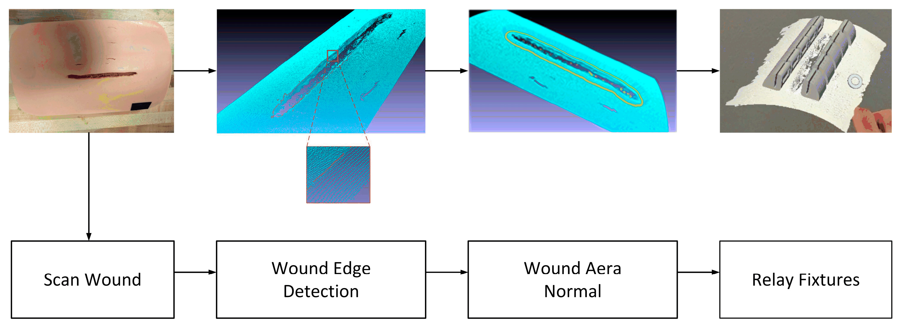
The autonomous robotic wound closure flowchart is shown in
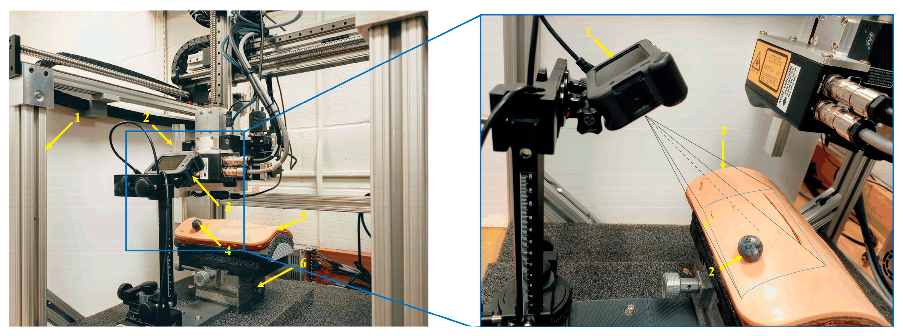
Figure 1. To close the wound, we used a laser scanner to scan the wound area and obtain the 3D point cloud of the wound area. Thus, the wound edge and its neighborhood area’s geometrical information can be computed. Based on the edge and the normal of the neighborhood area, we can plan the replacement of the fixtures: position and orientation. If the wound is not moving, the robot controller can readily guide the robot end-effector (containing the fixtures) to relay the fixtures along the wound edges with correct position and orientation. However, if the wound is not motionless for some reason, such as the patient’s aspiration, the robot will be unable to relay the fixtures with the correct position and orientation, potentially resulting in the wound closure failure. To challenge this issue, we developed a motion detection and robotic motion tracking control system for the robotic wound closure system, as shown in
Figure 2. VMDS is displayed at the top right part of
Figure 2, which consists of a GoPro camera and a passive marker attached to the wound surface. The robot and the fixture applier (end-effector) can place magnetic fixtures at desired positions on the wound surface. The VMDS is responsible for detecting wound motion and sending the wound position and orientation data to high-level robot controllers. The high-level robot controller sends a sequence of commands to the lower-level robot controller, which drives the end-effector to track wound motion and place the magnetic fixtures to close the wound. The motion platform has three Degrees of Freedom (DOF), two translations, and one rotation. The wound model is mounted on the top of the motion platform. Only Cartesian motion is considered in this research. The deformation of skin has been explored in our previous work [
29].
2.2. Motion Detection and Track System Configuration
The pin-hole camera model and the theory of VO are aptly covered in [
30]. There are a variety of VO methods [
31,
32], and the existing literature is often that cameras move in a world coordinate system (WCS) and VO measures the pose of the camera coordinate system (CCS) relating to WCS. However, in this configuration, the wound model moves in WCS, and the camera is not moving. So, the traditional VO cannot be directly used to measure the wound pose relating to WCS. To solve this issue, we must modify the traditional VO configuration by mounting the camera to WCS. Additionally, the features within the wound portion (moving in CCS) are used for feature-matching in VO. Therefore, the modified VO can measure the pose of the wound w.r.t CCS. Thus, the wound pose w.r.t WCS is attained by the coordinate transformation. Then, with the measurements of the pose of the wound, the SMC controller drives the end-effector to track the wound motion in WCS. Since the fixture applier is attached to the end-effector steadily, it can place the magnetic fixture in the desired position on the wound surface under the wound movement.
2.3. System Hardware and Communication Configuration
The system software is implemented on a Dell OptiPlex-7010 PC, and the code is written in C++ and Python 3.2. It has been verified on Ubuntu 20.04 LTS and Noetic ROS. The GoPro camera and the robot controller are connected to the computer via RS-422. The technical details of the hardware are described as follows:
GoPro HERO8 Black: Video: 4K60, 2.7K120; Photo: 12 MP; Frame rate: 100/120 fps.
Dell OptiPlex 7010 MT PC: CPU: 3.2 GHz; Memory: 3.8 GiB; Ubuntu: 20.04 LTS, Noetic ROS platform.
Robot specification: Workspace max up to 400(X) × 400(Y) × 300(Z) mm; Positioning accuracy: ±100 μm; Rotating accuracy: ±0.06 deg; Max load: 25 N; Max speed: 0.5 m/s.
Passive marker sphere: ABS material; 10 mm in radius.
3. Visual Motion Detection and Absolute Scale Estimation
The VMDS consists of a GoPro camera aimed at high-speed image flow (100/120 fps), and a passive marker which is used to reckon the scale factor. It is noted that the matching features must be inside the wound portion in the image. Otherwise, VO will fail. Therefore, the first step is to crop the wound portion in the image. In
Figure 1, the wound area inside the blue boundary is defined as the region of interest (ROI). The second step is to extract and match the features in the ROI between the initial image and the current image. However, the passive marker is not necessary to appear inside the ROI. In computer vision, the popular feature detection and match algorithms include SIFT, SURF, and ORB. SURF outperforms SIFT in matching speed, and its detectors are distributed over the image, while in ORB, the features are mostly concentrated in the image [
33]. Therefore, SURF is adopted in this work.
3.1. Camera Ego-Motion Estimation
In epipolar geometry, computing a camera ego-motion and 3D map from two consecutive image frames suffers from a so-called similarity ambiguity. Recall that in two-view geometry, the epipolar constraint is , where , are the corresponding pixel coordinates in two views and is the fundamental matrix. Assuming the camera matrix is known, the epipolar constraint equation can be expressed as , where , is the essential matrix, which can be expressed as , which is fully defined by the translation vector and rotation matrix which has three degrees of freedom. However, it must be stressed that has only two degrees of freedom because it is up to an overall scale, i.e., the translation estimation of the camera is up to a global scale. Hence, for convenience, is normally chosen as .
Subsequently, with the estimated camera ego-motion, the 3D scene reconstruction is only up to a global scale. To find the scale factor, we must acquire an object’s length based on the 3D reconstruction. The basic formula to find the scale factor is: , where is the ground true length of this object.
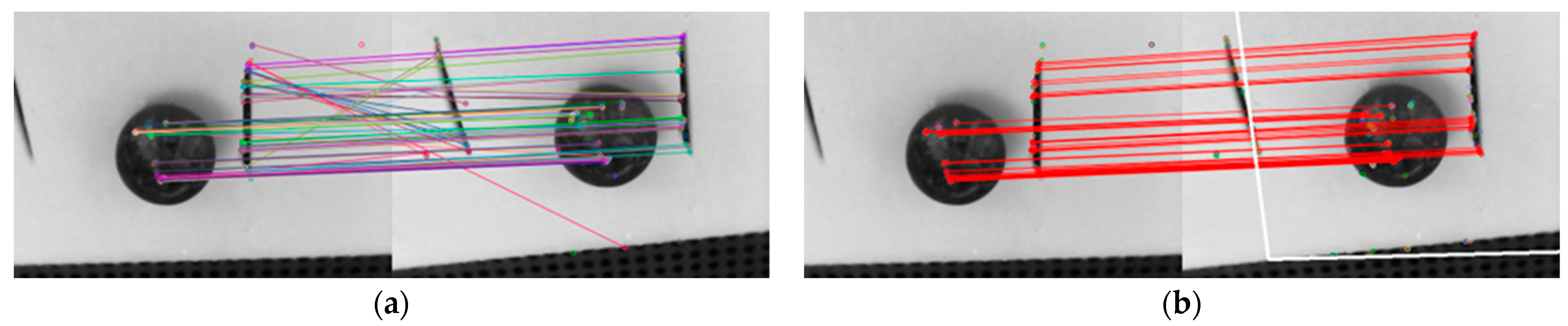
3.2. Removing Outliers of Feature Match
The features are detected and matched inside the ROI between two images. For the robustness of feature match, the Random Sample Consensus (RANSAC) method [
34] is used to help against outliers.
Figure 3 shows the feature matches of two images before and after using RANSAC. The fake feature matches are removed after RANSAC.
3.3. Scale Determination
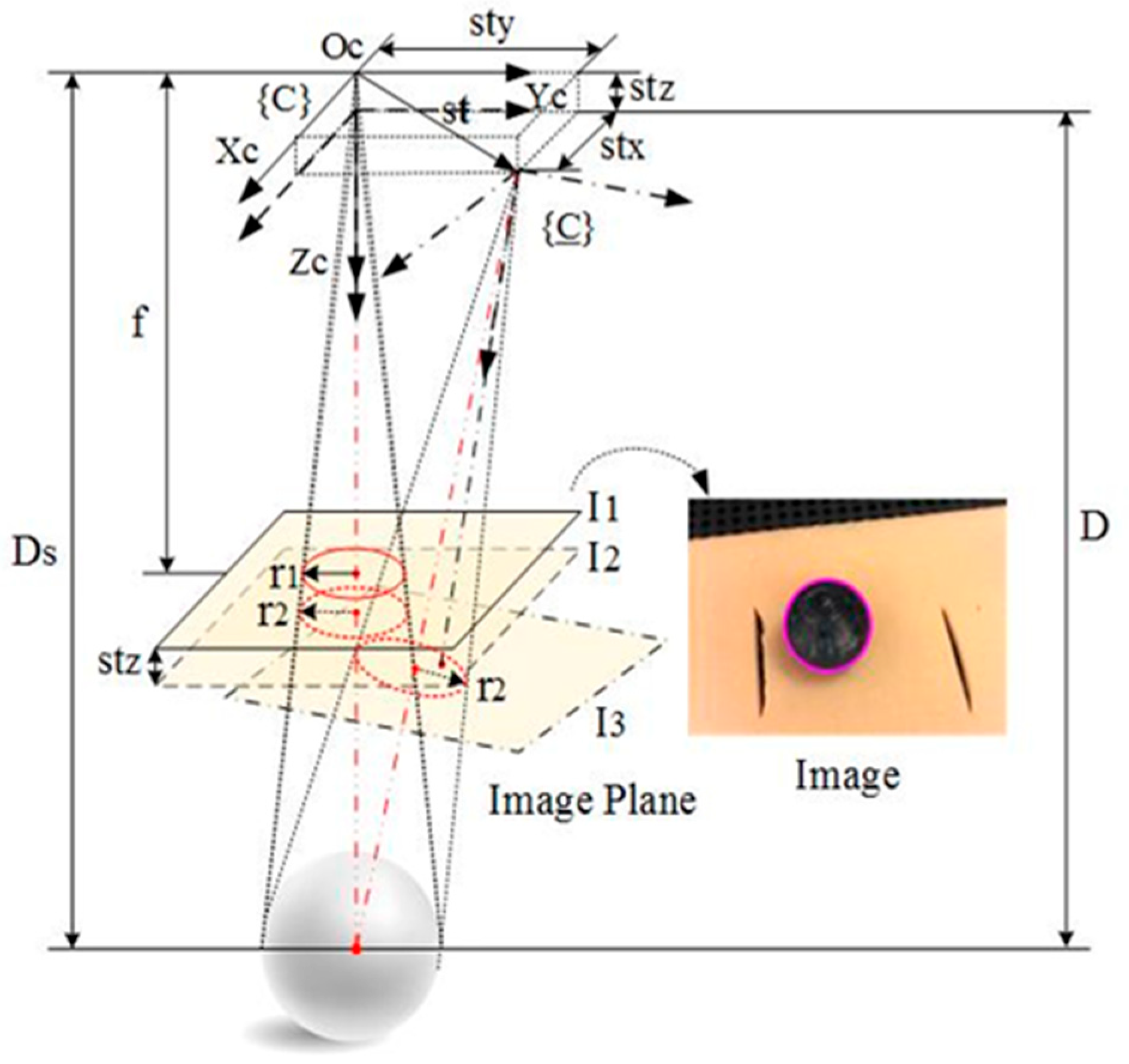
As shown in
Figure 4, a passive marker sphere is used for scale estimation. The passive marker sphere is glued on the wound surface as close to the image center as possible, and its contour in the image is approximately a circle which can be easily detected with the OpenCV Library.
The radius of the passive maker sphere’s contour will vary if the distance of the camera relating to the wound changes in 3D space. Assuming the radius of the passive marker sphere is known, the scale can be recovered according to the radius change of the passive maker sphere’s contour in the image. This is inspired by the invariant moments of an image. The radius of the circle can be thought of as invariant under three rotations around the camera optical coordinate axes if rotation angles around and are limited within ±10 deg. It is also invariant under two translations along and respectively, and only varies with respect to depth change, i.e., translations along .
In
Figure 4,
presents the translation vector of the CCS relating to the WCS, where
is the unit vector which is determined based on the essential matrix
, and
is the scale. If
is the component of
in the z-axis, the following equation is easily derived from
Figure 4.
where
is the depth of the marker’s initial position;
is the radius of the passive marker sphere;
are the radii of the circles in the image
and
respectively. The scale is expressed as:
where
is the component of
in
4. Motion Tracking Control
In this section, the high-level robot SMC controller is developed. First, the temporal fixture desired pose in the robot base coordinate system is computed with the VMDS measurement. Second, the coordinate systems are described, and the tracking errors are defined. Lastly, the kinematic equation of the robotic motion tracking system is given based on the kinematics scheme.
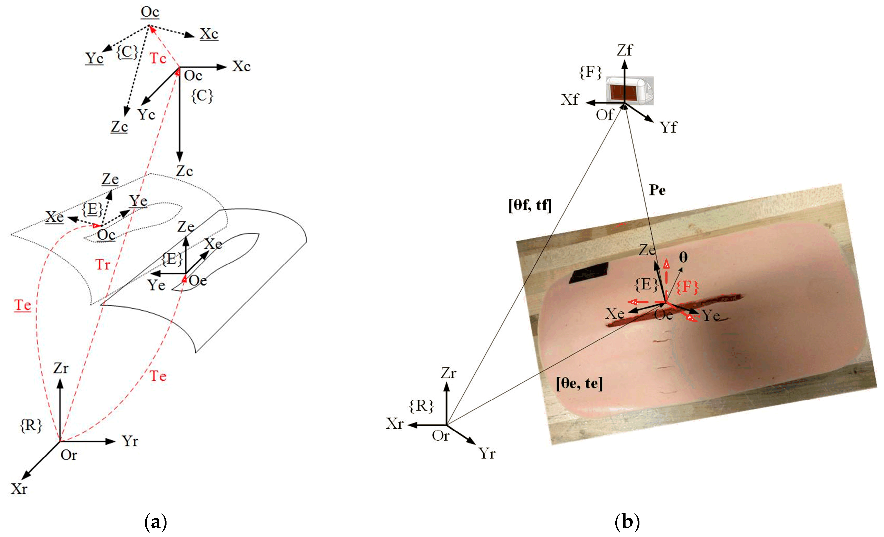
4.1. Fixture Desired Pose Measured from VMDS
As shown in
Figure 5a,
is the fixture desired coordinate system;
and
are the robot base and camera coordinate system, respectively;
represents the transformation from
to
;
is the transformation from
to
which can be decided in the step of planning magnetic fixture placement. If
moves to {
}
, will move to {
} if the camera moves with the patient.
is the transformation from
to {
}, which is measured by the VMDS. Then,
is the transformation from {
} to
and is computed as follows:
where
is measured by VMDS. To calculate
,
can be obtained by the system calibration, which is described in
Section 5.
4.2. Tracking Error Definition
As shown in
Figure 5b, {F} represents the coordinate system of the magnetic fixture which is loaded inside the fixture applier (see
Figure 1).
is the transformation matrix from {F} to {R}. The fixture desired pose on the wound surface is denoted as
which can be decided by the fixture planning program in our previous work [
35]. In addition,
represents translational vector of {E} in {R},
Euler vector of {E} in {R}, and
represents translational vector of {F} in {R},
Euler vector of {F} in {R}. And
is also the current pose of
in {R}. If
is the translational vector from {E} to {F} expressed in {R}, then
. Euler angle vector from {E} to {F} in {R} is
. The tracking error is finally defined as the transformation from {E} to {F} expressed in {R}, i.e.,
. The goal of controller design is that the controller can drive {F} to track and catch up {E} in a short period under the motion of wound in the robot-base coordinate system.
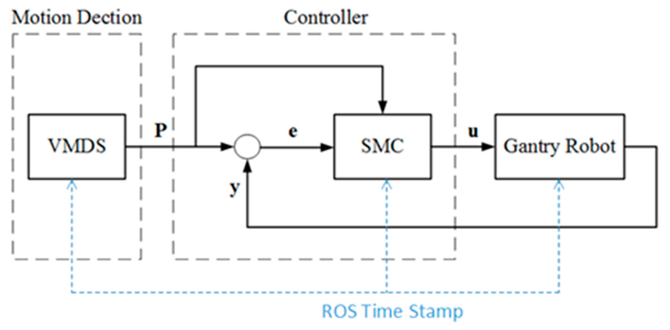
4.3. Varying Target SMC Controller for Robotic Motion Tracking System
All the diagram of the motion detection and robotic tracking control system is shown in
Figure 6.
P represents the measurement from VMDS,
y is the encoder feedback of the robot,
e represents the track error, and
u is the control signal. The SMC controller drives the end-effector to track the patient motion, and the tracking error approaches null in a finite time. Robot Operating System (ROS) is the framework. The synchronization between the VMDS and the SMC controller is realized by triggering with a ROS timestamp at sampling time.
4.3.1. Robot Kinematic Model
The state variable is defined as:
where
is the current fixture pose expressed in {R},
the derivative w.r.t time of
. The robot dynamic equation is written as:
where
is the control signal to the robot controller.
4.3.2. Tracking Error Dynamic Model
The state variable vector of tracking error is defined as:
where
is the pose error vector and
the derivative w.r.t time of the pose error vector. As shown in
Figure 5, it is clear that
where
is the error term of
and is assumed to be a wiener process with a mean of 0 and standard deviation
. That is,
∼
. In particular,
is independent from
and the variance
does not depend on
. The condition described here requires that the variance of
is increasing with respect to time over all values of
.
Substitute (5) into (9) and consider the uncertainties in the system, the tracking error kinematic equation is described as follows:
where
is the control signal to the robot controller;
is the error term which includes both system uncertainties and VMDS measurement error term, i.e.,
. The components
are assumed to be bound,
4.4. Varying Target Sliding Mode Control (VT-SMC)
Varying Target Sliding Mode Control (VT-SMC) is an advanced control strategy that combines conventional sliding mode control with adaptive target adjustment to improve system performance, particularly in scenarios with changing operating conditions or uncertain parameters. The key innovation in VT-SMC is the dynamic adjustment of the target/reference trajectory. The sliding surface is modified to account for time-varying performance requirements. Therefore, VT-SMC allows for better tracking of non-stationary references or changing operating conditions.
4.4.1. Theoretical Foundations of Sliding Mode Control
Sliding Mode Control is a robust control technique that forces a system to follow a predefined trajectory (sliding surface) despite disturbances and uncertainties. It works by applying a discontinuous control law that switches rapidly to keep the system on track. The key theoretical aspects include:
The sliding surface is typically chosen as a linear combination of tracking errors. Define a sliding surface (where the system should stay). For a second-order system, it can be defined as:
For a tracking error
, a common choice is:
where
, the error decays exponentially.
In this research, the sliding surface is naturally defined as follows:
where
is defined as a sliding surface vector. The components
are the sliding surfaces w.r.t
, respectively.
4.4.2. System Stability Analysis and Control Law
To drive the components of the sliding surface vector in Equation (12) to zero in finite time, the condition
must hold. The control law typically has two components:
Equivalent control for nominal system dynamics (obtained by setting
Switching control for robustness (handles disturbances):
We resort to the Lyapunov function technique
dynamics to achieve this goal. The Lyapunov function candidate is selected as:
To ensure the asymptotic stability of the system equation at the equilibrium point, the following conditions must be satisfied:
Condition (b) is obviously satisfied. To achieve finite-time convergence, condition (a) can be modified to be
In fact, separating variables and integrating inequality above over the time interval
yields:
Thus,
comes to zero in finite time:
Therefore, the robot control signal
satisfying Equation (19) drives
to zero in finite time and keeps it at zero thereafter. Differentiating Equation (13) w.r.t time and substituting Equation (12) into the result, one has
Assuming
, and using Cauchy–Schwarz inequality, thus,
Equation (22) is automatically satisfied. From Equation (24), it can be induced that
where
.
Lemma 1. (see Appendix A) says that holds. Applying Lemma 1 to (25) shows that Equation (23) is automatically satisfied if selecting
, where
is a positive constant and is also known as control gain.
Therefore
. To reduce the shattering in SMC, an approximate is given as:
where
denotes vector element-wise division operator;
denotes vector element-wise absolute operator. The control law:
The velocity control signal to the robot controller is expressed as:
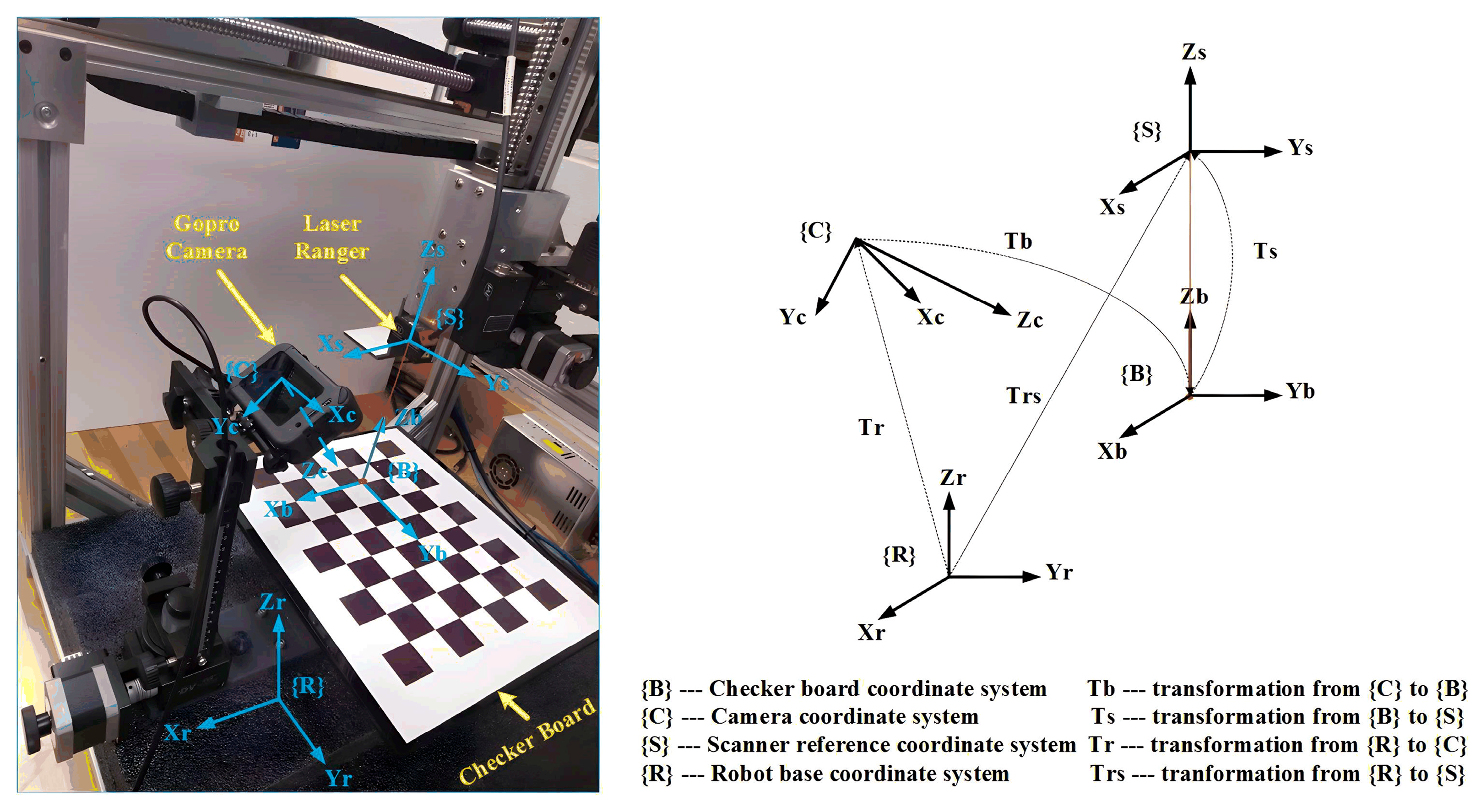
5. Motion System Calibration and Validation
The calibration system setup is shown in
Figure 7. We use a camera calibration checkerboard and a laser ranger in the calibration process. The laser ranger (Model: ILD1420-100) is to complete operations with specified measurements.
5.1. Coordinate System Definition
In
Figure 7, {
C} and {
R} represent the coordinate systems of the camera and the robot base, respectively. The transformation from {
R} to (
C) is denoted as
. And {
B} and {
S} represent the coordinate systems of the checkerboard and the laser ranger, respectively. The transformation from {
B} to (
S) is denoted as
. Meanwhile,
represents the transformation from {
R} to (
S), and
translation from {
C} to {
B}. To validate VMDS,
the camera’s position and orientation in the robot base coordinate system must be determined.
5.2. Determination Method of
Since the laser ranger is rigidly mounted to the robot end-effector,
is easily derived from the forward kinematics of the gantry robot and the laser ranger installation parameters. Because
of {
B} is aligned with
of {
S},
contains only translation and is denoted as
, where
h is the reading of the laser ranger. The planar grid structure of the checkerboard defines many key points in the camera image,
is easily determined by solving the “points to points problem” in the OpenCV Library. In
Figure 7, the following equation holds:
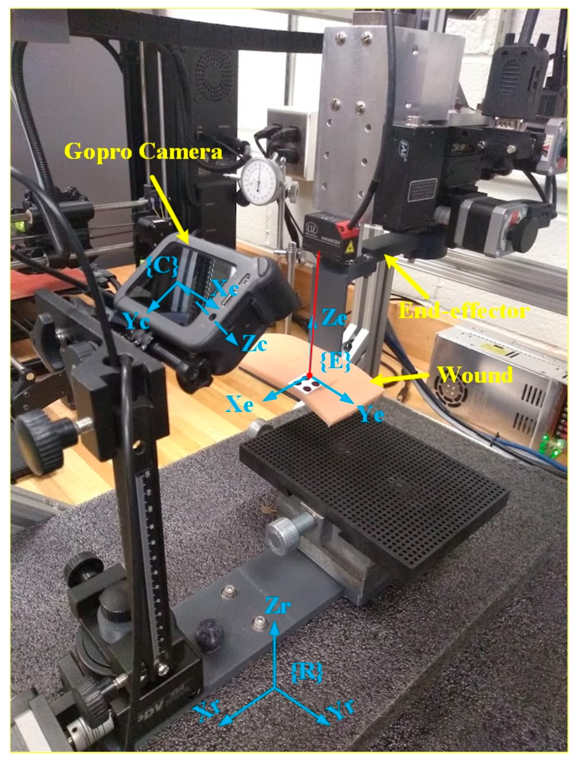
5.3. VMDS Calibration and Validation
System validation ensures that the VMDS design meets performance requirements under real-world conditions. To validate the proposed VMDS, a wound model is attached with non-slip clamps to the robot end-effector, as shown in
Figure 8. The wound movements in the robot’s base frame are recorded with robot controllers and serve as ground truth of the wound motion. If the robot end-effector is commanded to known positions and orientations in 3D space with the wound model attached, the wound motion in the robot’s base frame is detected with VMDS. When evaluating the positional and orientational accuracy of VMDS, we need to compare its actual position and orientation (measured) against the ground truth (reference).
In the evaluation, we control robot end-effector (with a wound model) move displacement within
(20 mm),
(20 mm),
(10 mm),
(10 deg),
(10 deg),
(10 deg) around its original position. The defined 3D region is divided into grid patterns with 2 mm spacing, and each grid is divided into 2 deg for α, β, and γ. The robot end-effector is moved to each grid point, and the position and orientation of the wound are measured using VMDS. The mean error (µ) and standard deviation (σ) of the evaluation results are listed in
Table 1.
System validation ensures that the developed system performs as intended in real-world conditions. Validation accuracy directly affects the overall system accuracy, which is critical for patient safety and surgical success. Below is a detailed breakdown of how the validation processes of VMDS influence system performance. As the robot tracking controller depends on the VMDS measurements, the accuracy of VMDS has a direct impact on the precision and repeatability of the overall wound closure system. Poor validation will misalign incisions or cause accidental tissue damage. The calibration and validation procedure must follow Compliance FDA’s 510(k) or PMA Process (Mandatory for market approval).
6. Simulations and Experimental Results
In this section, an extensive simulation study is conducted on MATLAB 2022a to investigate the performance of the proposed control scheme and compare it with the PID in the presence of a disturbance. The VMDS and robotic motion tracking control system have been tested on the robotic wound closure system to verify the effectiveness of the proposed motion detection and robotic motion tracking control scheme.
6.1. Simulations of Motion Tracking Performances
In the simulations, the patient’s motion is known. The motion track performance of the SMC control is evaluated and compared to PID control under the given patient motion. The PID was tuned by the PID Tuner in Simulink of the PID controller. The parameters of the SMC and PID controllers in the simulations are listed in
Table 2.
The motion of a patient is set regarding the theoretical model of respiratory motion [
36]. The
where
position of organ at time
position at expiration,
amplitude (extent) of motion,
position at inspiration,
period of motion, and
degree of asymmetry (larger
more time near expiration). In this study, nominal values of
15 mm (amplitude of motion) and
3 (degree of asymmetry) were selected based on general observations of diaphragmatic movement under fluoroscopy for many patients. The normal range of respiratory rates for an adult is 12–20 breaths per minute at rest,
. In reality, the amplitude of patient breathing may vary over time or the patient may occasionally take deep breaths during the course of treatment. Such variations may compromise the selection of a single amplitude for the motion and/or a single degree of asymmetry for the breathing. Considering that real surgical scenarios involve irregular respiratory patterns, currently, experiments use controlled breathing with coughing or sudden patient movements.
The simulation results are given in
Figure 9,
Figure 10,
Figure 11 and
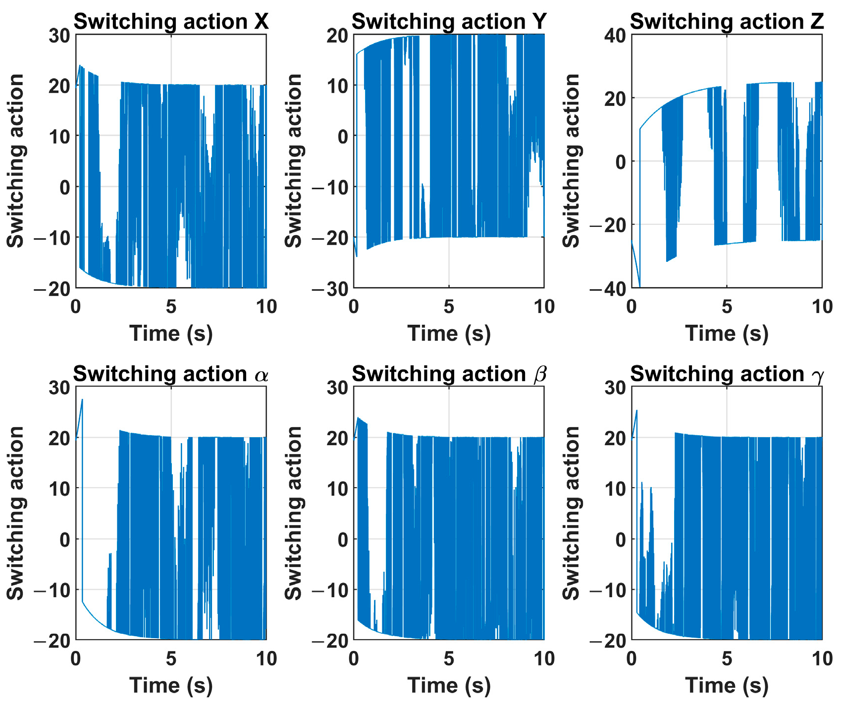
Figure 12. The switching action of the control signal
u of the sliding mode controller is given in
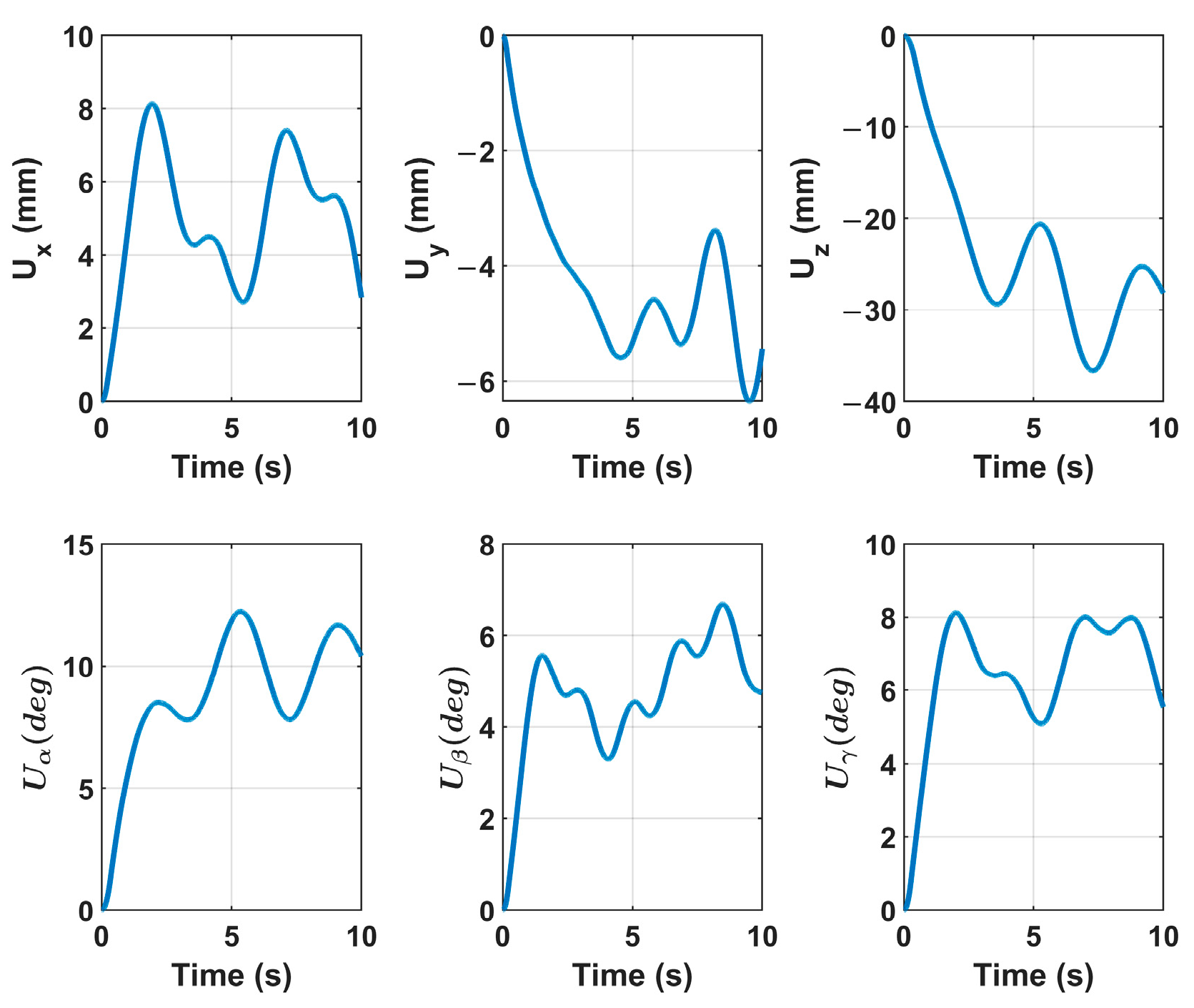
Figure 8. The velocity control signal
U to the robot controller is shown in
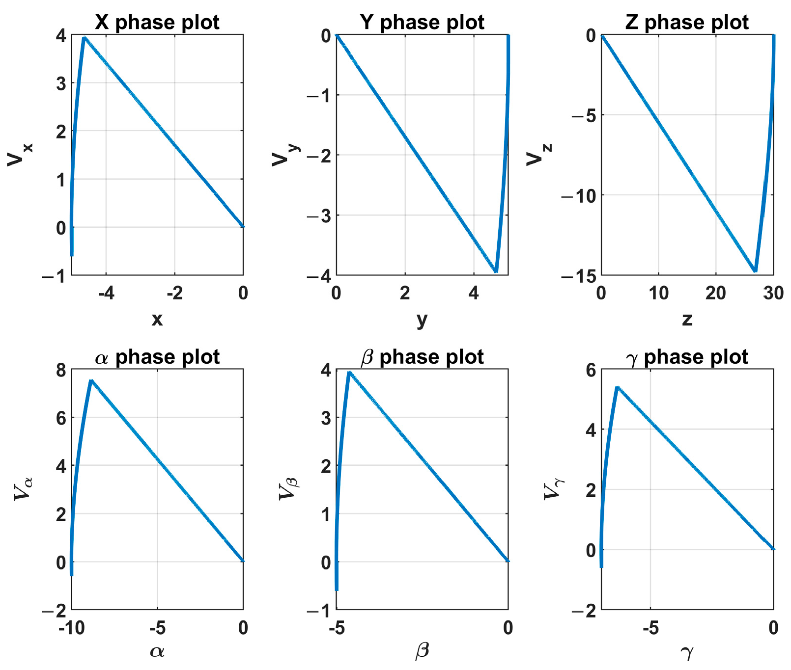
Figure 10.
Figure 11 depicts the phase plot of the sliding mode controller. One can see that the system’s state variables became zero along the sliding surface. The motion tracking performances of the sliding mode controller and the PID controller are given in
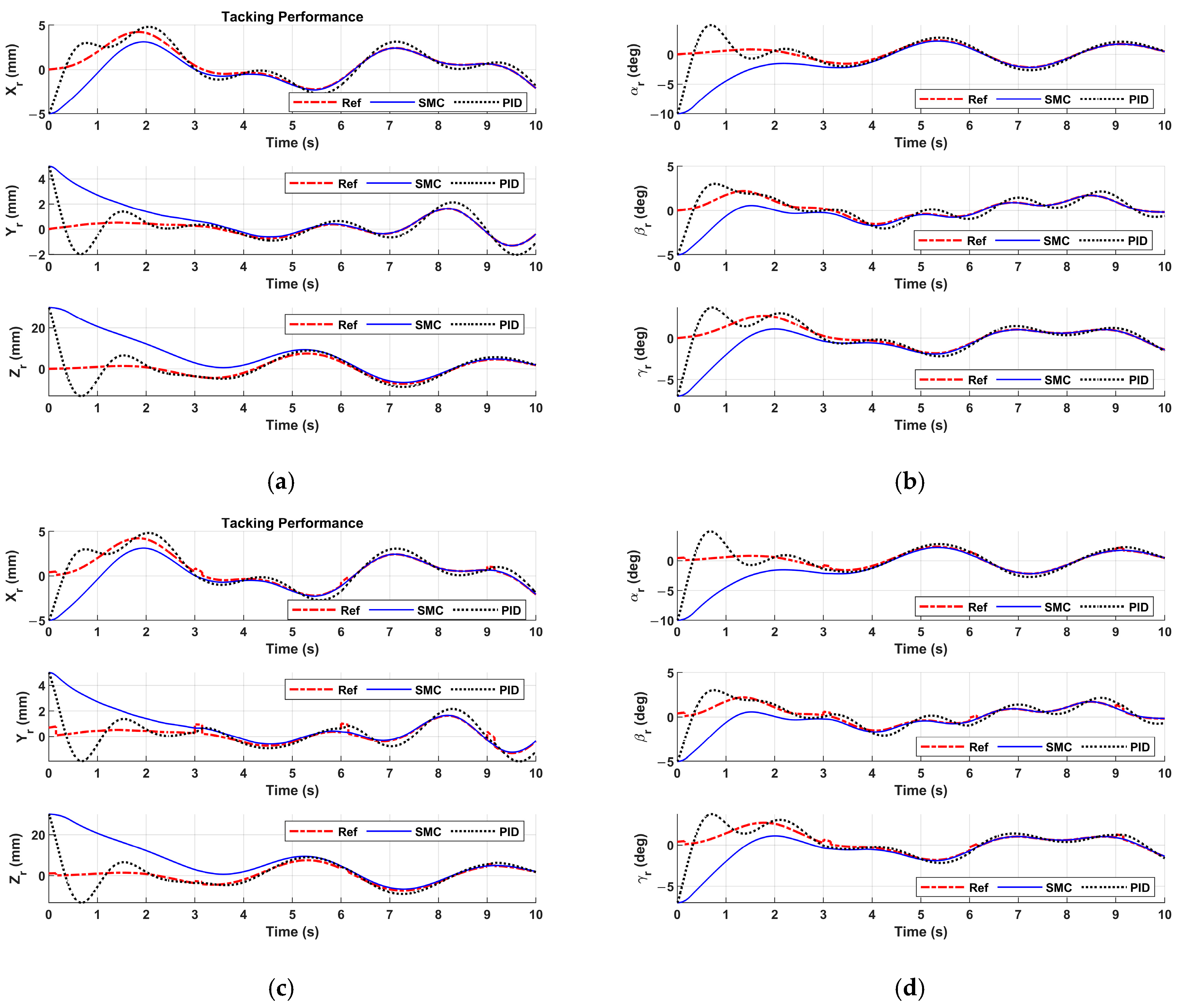
Figure 12.
Figure 12a,b show the patient motion tracking results of regular breathing. One can see that the sliding mode controller is able to track the patient motion of regular breathing. To mimic more realistic and complex scenarios in real surgeries, the patient breathing with coughing is studied. If coughing occurs at 3 sec, 6 sec, and 9 sec in
Figure 12c,d, coughing disrupts regular breathing motion, causing sudden spikes in displacement (abrupt increases in amplitude). The patient motion tracking results are represented in
Figure 12c,d. The motion tracking returns to baseline after cough (i.e., 0.2 sec).
Figure 12 reveals that the sliding mode controller drives the end-effector to track the patient motion robustly. In
Figure 12, the PID controller fails to track the patient motion. The tracking error of the sliding mode controller monotonically converges to zero, and the tracking error of the PID controller oscillates.
6.2. Experiments on the Robotic Wound Closure System
To test the performance of the proposed control scheme, we carry out experiments on the robotic wound closure system. The sampling rate in the experiments is 30 Hz. The parameters of the initial pose of the fixture applier (end-effector) and the desired pose of the fixture applier (the poses are expressed in the robot base coordinate system) are listed in
Table 3.
Table 3 performance may degrade under extreme lighting conditions (e.g., low light, shadows, or glare), affecting feature extraction. The system’s accuracy may vary across skin tones, textures, or demographic groups.
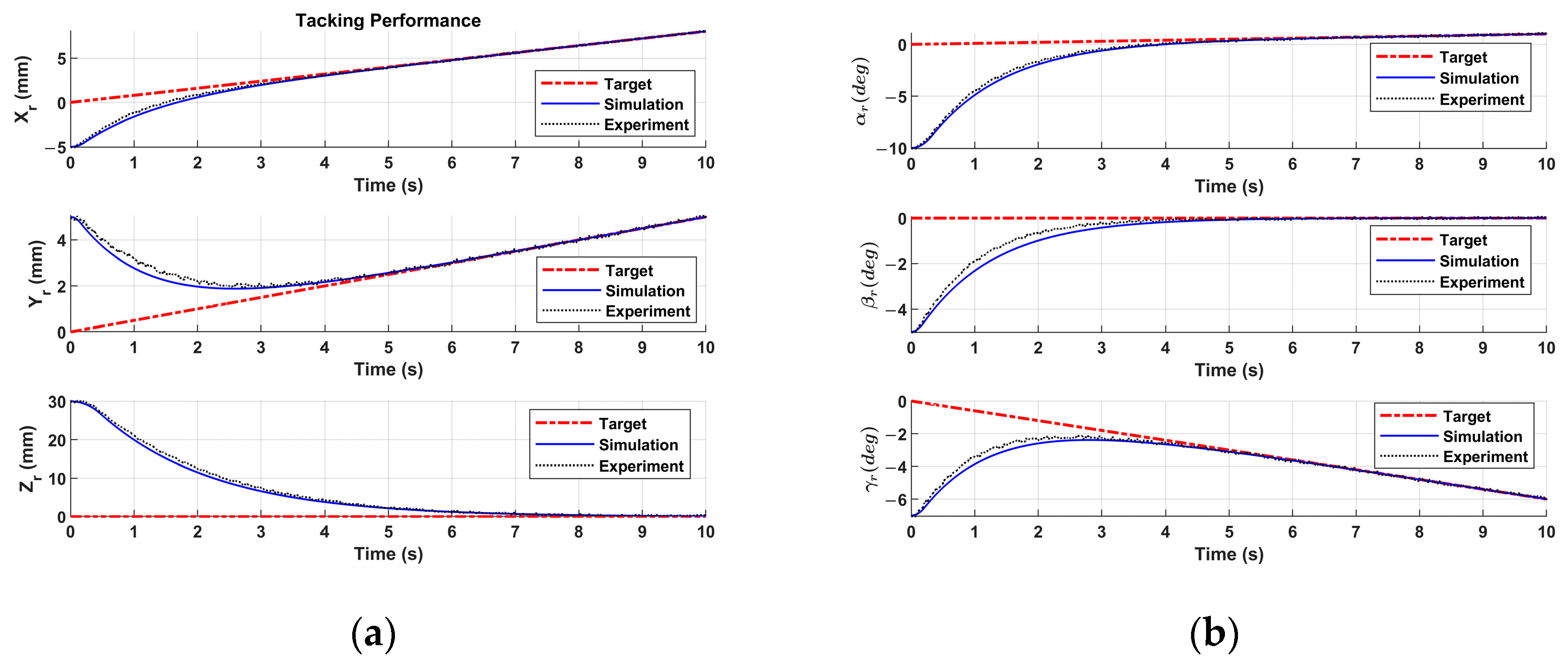
Figure 13 shows the experimental results. To revalue the performance of the sliding mode controller in the experiment, a simulation with the same parameters as the sliding mode controller in the experiment is conducted, and the simulation results are also plotted in
Figure 13.
In
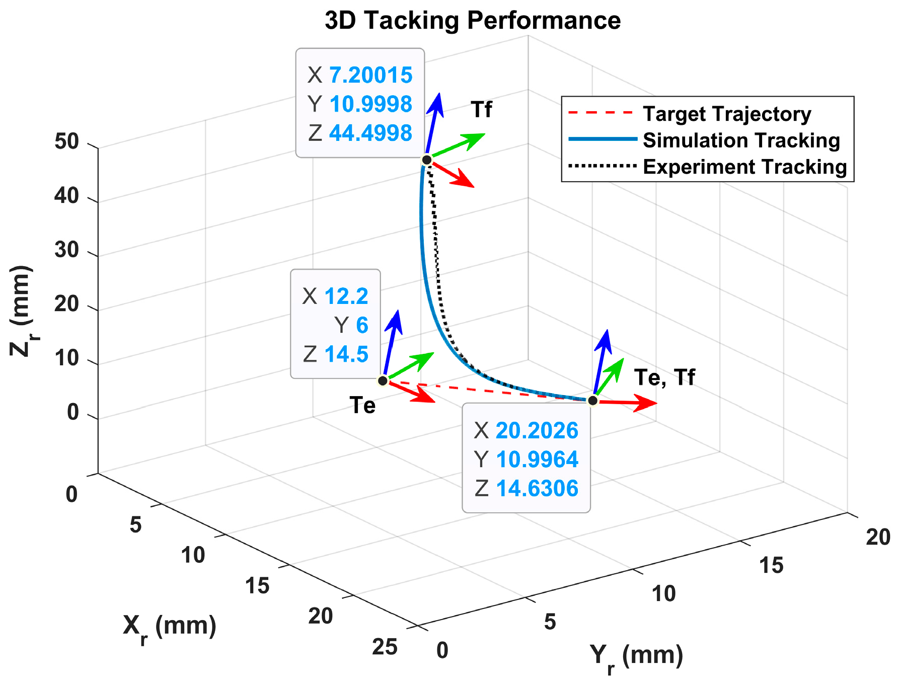
Figure 13, one can see that the motion tracking performances of the sliding mode controller in the experiment and the simulation are coincident. The sliding mode controller in the experiment drives the fixture applier to track the moving wound and catch the moving wound in 6 sec. The 3D position trajectories of the fixture applier in the experiment and simulation are plotted in
Figure 14.
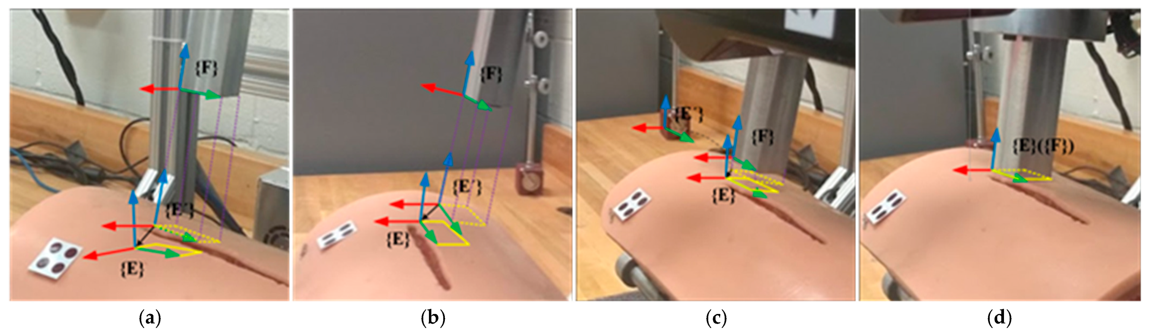
The wound motion tracking process in the experiment is illustrated in
Figure 15.
Figure 15a shows the initial position and orientation of the wound and the fixture applier. The dashed rectangle represents the projection of the fixture applier onto the wound surface. The solid rectangle represents the goal position and orientation of the fixture applier. It is shown that the proposed sliding mode controller drives the robot to move the fixture applier to track and catch the target on the moving wound.
The developed patient motion tracking system can enhance the precision of wound closure but introduces unique safety risks and cybersecurity vulnerabilities. Below is a detailed breakdown of physical safety protocols and measures to ensure patient and system security.
Physical Safety Measures for Surgical Robots
- (1)
Emergency Stop Mechanisms
- (2)
Collision Avoidance Systems
Intraoperative Safety Protocols
- (1)
Real-Time Monitoring
Haptic feedback alerts if excessive force is applied.
AI-driven anomaly detection (e.g., unexpected bleeding patterns).
- (2)
Redundancy and Fail-Safes
Dual motors for critical joints (if one fails, backup engages).
Battery backups in case of power failure.
7. Limitations and Constraints
While the proposed system demonstrates promising performance under controlled conditions, several limitations must be acknowledged, along with potential mitigation strategies for real-world deployment. It should be noted that a critical limitation in the study is the failure to account for inter-patient variability. It can significantly impact the reliability and generalizability of a wound closure system. Below is a structured breakdown of how individual differences could affect performance, along with potential solutions:
- (1)
Camera Occlusion and Partial Visibility
The system may fail to detect patient poses if the patient is partially occluded (e.g., by objects, clothing, or other body parts). Mitigation: Incorporating multi-camera setups or depth sensors can improve robustness. Temporal smoothing algorithms (e.g., Kalman filters) can also help infer occluded poses based on prior frames.
- (2)
Illumination Variability and Skin Texture
Performance may degrade under extreme lighting conditions (e.g., low light, shadows, or glare), affecting feature extraction. The system’s accuracy may vary across skin tones, textures, or demographic groups. Mitigation: Leveraging infrared cameras or adaptive histogram equalization techniques can enhance invariance to lighting.
- (3)
Potential Medical Bias
To ensure equitable representation and mitigate bias, diverse skin tone models are included in both computational models and physical prototypes where applicable. For optical-based sensing/actuation systems, skin tone diversity is incorporated via spectral reflectance models spanning melanin concentrations (0.5–43%) [
37] and Fitzpatrick Types I–VI. Physical prototypes are tested on synthetic skin phantoms with controlled pigmentation [
38]. Quantitative comparison of system performance across skin tones (e.g., signal-to-noise ratios, detection accuracy) is added.
- (4)
Real-Time Processing Constraints
Heavy computational demands may limit deployment on the developed system. Mitigation: resorting to deep learning models, e.g., Mobile Net, Efficient Net, can optimize speed without significant accuracy loss.
- (5)
Run Stably for a Long Time
While the article’s limited-time experiment provides proof-of-concept, transitioning to long-term clinical use demands additional engineering refinements, rigorous testing, and regulatory scrutiny. If these challenges are addressed, the system could theoretically maintain quality and safety, but further evidence would be required to confirm this.
Addressing these limitations will require advancements in sensor fusion and adaptive algorithms. Real-world testing in diverse environments is critical for further validation.
8. Discussion
In the operating room, permissible error thresholds for wound closure are guided by principles of precision, safety, and optimal healing. While specific institutional protocols [
39,
40] may vary, general standards include: (1) Wound Edge Alignment: Tolerable misalignment: <2–3 mm for most incisions (e.g., abdominal, orthopedic); (2) Bite Depth: Even depth on both sides (asymmetry >2 mm may compromise healing); (3) Delayed Primary Closure: Generally acceptable within 6–24 h for contaminated wounds (varies by case).
An extensive simulation study is conducted to evaluate the performance of the robotic motion tracking control system. The simulation results demonstrate the effectiveness of the proposed system in driving the end-effector to track and follow the wound movement. The experiments are also carried out on the robotic wound closure system. The experimental results show that the proposed motion detection and robotic motion tracking control system can drive the end-effector to track and follow the target on the wound surface under the wound movement. The error of motion detection is less than 0.67 mm between the VMDS and real motion for translations and 0.26 degrees for rotations. The relay error is 0.86 mm under the patient motion (translation: 15 mm, orientation: 5 deg) in the autonomous robotic wound closure system. Experiments show that the developed system satisfies the requirements for successful wound closure applications in the operating room.
This research developed a patient motion detection and robot tracking control system for wound closure. The motion detection in the proposed system has high sensitivity, specificity, real-time response, and clinical applicability compared to the existing solutions. Comparative analysis for patient motion detection systems is summarized in
Table 4. The proposed solution provides a real-time response with sub-mill precision measurement for patient motion detection. Also, the developed system has small real-time latency (<100 ms) and space efficiency, which makes it easy to integrate with medical robots like surgical assistants, rehabilitation robots, or delivery robots.
9. Conclusions
In this paper, a visual motion detection and robotic motion tracking control system is developed for the robotic wound closure system. Utilizing the measurements of the VMDS, a high-level robot controller based on a varying target SMC scheme is implemented to effectively drive the end-effector to track the wound movement. The simulations are conducted to validate the effectiveness of the proposed system in driving the end-effector to track and follow the target coordinate system. Furthermore, experiments aimed at evaluating the performance of the proposed system are carried out on the robotic wound closure system. The results indicated that the proposed motion detection and robotic motion tracking control system successfully guided the robot end-effector in executing fixture placements on the moving wound while exhibiting resilience to the robot errors and external disturbances.
The key contributions of this work include: (1) developing a monocular VO system, the scale of which can be estimated by integrating a passive marker, (2) designing a high level robot controller based on varying target SMC scheme, (3) establishing the overall control stability of the control scheme, ensuring converge of the proposed motion detection and robotic motion tracking system, (4) implementing and verifying the motion detection and robotic motion tracking control system on the robotic wound closure system. The simulation and experimental results have demonstrated that the proposed system achieves robust motion-tracking, effectively addressing robot errors and external disturbances, and enables swift fixture placement on the moving wound surface.
While this study demonstrates promising results, several key directions will be critical for advancing this technology toward clinical adoption and real-world application. Future works will focus on (1) Clinical translation and validation: Conduct large-scale, multicenter clinical trials to validate performance of aero diverse patient population; Explore regulatory pathways (e.g., FDA/CE approval) by addressing safety, reliability, and ethical considerations. (2) Hardware Optimization: Improve power efficiency and wireless connectivity for real-time data transmission; Enhance sensor robustness against motion artifacts, environmental noise, and physiological variability. (3) Real-World Deployment: Test the system in uncontrolled environments to assess resilience under variable conditions; Integrate with real medical platforms for clinician feedback. By addressing these challenges, the proposed technology can transition from a proof-of-concept to a practical tool for precision medical platforms.


