Article

Design and Test of a Magnetorheological Damper of a Multi-Layered Permanent Magnet

1
Key Laboratory of Fluid and Power Machinery, Ministry of Education, Xihua University, Chengdu 610039, China
2
Institute for Catalysis, Hokkaido University, Sapporo 001-0020, Japan
*
Author to whom correspondence should be addressed.
Actuators 2025, 14(6), 271; https://doi.org/10.3390/act14060271
Submission received: 12 April 2025 / Revised: 26 May 2025 / Accepted: 28 May 2025 / Published: 29 May 2025

Abstract

:
To effectively suppress spindle vibrations in rotating machinery, magnetorheological (MR) dampers, as an ideal vibration control device, have attracted attention. To enhance the vibration damping effect, in the paper, a MR damper vibration with a multi-layered permanent magnet as the magnetic source is designed, and the self-made magnetorheological fluid is used as the damping medium. The mechanical properties of the MR damper were obtained through testing and calculation. On this base, both simulation and experimental methods are used to demonstrate the effectiveness of the multi-layered permanent-magnet MR damper. The simulation results show that the critical speed increases greatly for the first four modes. The experimental results show that the Y-direction displacement decreases greatly, especially at 1800 rpm and at 3400 rpm, after applying the MR damper. The vibration displacement at 1× frequency shows a 69.74% reduction at 2600 rpm and a 65.69% reduction at 3200 rpm in the Y-direction after applying the MR damper. The effectiveness of the multi-layered permanent magnet MR damper in rotor vibration suppression was confirmed.

1. Introduction

During operation of large rotating machinery, the mechanical unbalance caused by self-weight of machinery and magnetic pull unbalance appears, which severely interferes with normal unit operation [1,2,3], and dampers are required to suppress shaft vibration. Traditional passive dampers, such as hydraulic viscous dampers, solid viscous dampers, and friction dampers, have the problems of high energy consumption and time lag. In contrast, MR dampers have attracted attention due to their faster response speed and lower power consumption [4].
The MR damper, as a new type of intelligent vibration control device, contains magnetorheological fluid (MRF), which can undergo a rapid transformation from a liquid state to a semi-solid state under an applied magnetic field, and the process is continuous and reversible. Replacing traditional passive control components with MR dampers can effectively adjust system damping and stiffness, making them an ideal vibration control device [5]. The performance of MRFs plays a crucial role in the effectiveness of MR dampers. MRF is a suspension formed by dispersing micron-sized magnetic particles into a base liquid along with appropriate additives. The increase in temperature will make the viscosity of the MRF reduce, which is conducive to the stable operation of the rotor at low rotational speeds [6]. Sometimes the temperature will bring adverse effects and, at this time, it is necessary to increase the cooling system. It is of note that in the absence of a magnetic field, it behaves as a freely flowing Newtonian fluid. When a magnetic field is applied, the randomly distributed magnetic particles align into chain-like structures along the field direction, causing a sharp increase in the fluid’s viscosity [7] and exhibit Bingham plastic behavior similar to a semi-solid [8,9]. This magnetic field-controlled rheological property has the characteristics of low energy consumption [10], rapid response [11], and continuous apparent viscosity adjustment [12], which provides the foundation for the application of MR dampers in damping [13], braking [14], ferrofluid pump [15], polishing [16], and sealing [17].
MR dampers represents a primary application [18,19], which are widely applied in suspension systems and rotor systems. British professor Jeffcott proposed the Jeffcott rotor model, which subsequently garnered widespread attention from researchers [20]. It was demonstrated by Wang Jianxiao et al. [21] that the amplitude of the rotor system reduced greatly after applying an MR damper, in addition to adjusting the magnetic field intensity. It was shown by Zhao et al. [22] that after applying the MR dampers, the system’s vibration amplitude decreased from 0.0049–0.0055 m to 0.0014–0.0016 m, achieving a 70% reduction. It was reported by Zhang [23] that the amplitude variation of a rotor with a diameter of 1000 mm decreased from 6.5 × 10⁻³ m to 1.06 × 10⁻³ m after applying the MR damper. In general, these findings all indicate that the MR dampers effectively reduce vibration.
With the development of MR dampers, they can be categorized into coil-type [24] and permanent-magnet-type [25] MR dampers based on the magnetic field source. The damping force of coil-type MR dampers is regulated by varying the current in the electromagnetic coil. The force is affected by the magnetic field strength of the permanent-magnet-type MR dampers. For coil-type MR dampers, it was demonstrated by Wang et al. [26] that the amplitude of the rotor system can be reduced by increasing the current. However, when the current exceeded a certain range, the damper exhibited nonlinear vibrations. It was found by Ma et al. [27] that after applying the MR damper, the amplitude decreased effectively by 64.37% at the first critical speed. However, during the increase in current, the rotor system exhibited unstable and the nonlinear vibration behavior. Moreover, coil-type MR dampers will fail due to power interruption, which may result in severe accidents.
Therefore, permanent-magnet-type MR dampers attract widespread attention for their higher safety. It was reported by Liu et al. [28] that the damping force of an MR damper increased from 0.56 kN to 2.32 kN by embedding permanent magnets with different arrangement angles to alter the magnetic field direction and strength. It was reported by Kim et al. [29] that the magnetization zone was adjusted by modifying the MRF housing shape in a permanent-magnet MR damper, and the highest damping force of 28 N was obtained. It was shown by Khedkar et al. [30] that the damper force of the MR damper under the magnetic field of 7000 G is higher than that of 2000 G and 4000 G. These studies confirm that the rotor system vibrations can be effectively controlled by permanent-magnet MR dampers, and the factors such as magnetic pole orientation, housing geometry, and magnetic field strength all will significantly affect the damper force.
To obtain a permanent-magnet-type MR damper with simple design and strong vibration reduction effect, in this paper, a MR damper with a multi-layered permanent magnet is designed. The magnetic field strength increases by increasing the number of layered permanent magnets, and, thus, the damper force increases. The vibration reduction effect of the damper designed in this paper is verified through simulation and experiments.

2. Damping Strategies for Vibration Attenuation

Damping systems can be categorized into passive dampers, semi-active dampers, active dampers, and hybrid dampers based on different vibration control methods. However, these damping systems exhibit variations in power capacity and size constraints. To address this issue, the paper compared their key parameters such as motor power and dimensions, as summarized in the following Table 1. These include hydraulic dampers, electrorheological dampers, piezoelectric actuators, and rubber rings
MR dampers can be divided into semi-active dampers and passive dampers according to the magnetic field control mode, and can also form hybrid dampers by combining with hydraulic dampers. They are suitable for a wide range of motor sizes and power ranges, making them a better vibration reduction solution. Therefore, this paper designs a permanent-magnet-type passive MR damper. Meanwhile, a rotor system with a power of 3.7 kW, a shaft diameter of 10 mm, and a shaft length of 820 mm is designed for vibration reduction experiments. This damper is suitable for low-power rotor systems, but the size and magnetic field strength of the designed MR damper can be adjusted according to actual motors, making it adaptable to rotor systems with larger power ranges and sizes, such as hydroturbines, hydrogenerators, and other mechanical equipment.

3. Design of MR Damper and Its Mechanical Properties Experiment

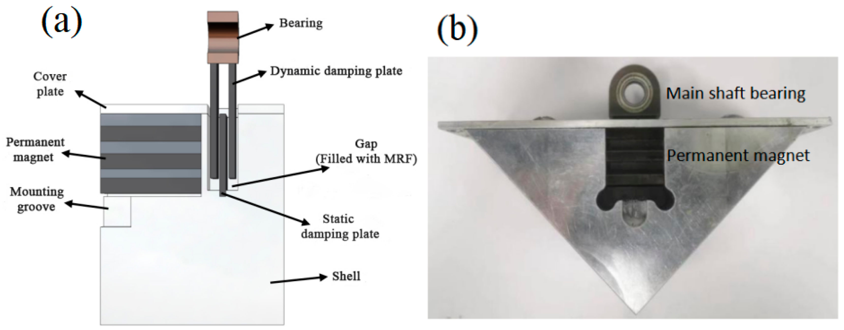
3.1. The Structure and Parameters of the MR Damper

The structural and physical diagram of the MR damper is shown in Figure 1. As illustrated, two moving damping plates and one stationary damping plate are contained in the MR damper The bearing is welded to the moving damping plates, while the stationary damping plate is fixed at the base. The moving damping plates are positioned at 5 mm above the base, with 1 mm gaps between the moving damping plates, stationary damping plate, and housing walls. These gaps are filled with MRF. During vibration of the rotating shaft, the MRF undergoes shear motion, and a damping force generates under a magnetic field. The structural parameters of the MR damper are listed in Table 2.
The performance parameters of the MRF are listed in Table 3. The main steps for preparing magnetorheological fluid (MRF) are as follows. Firstly, the carbonyl iron particles (CIP) are activated with dilute hydrochloric acid, and the concentration of dilute hydrochloric acid is 0.5 mol/L. Secondly, the activated particles are coated with a silane coupling agent (Dodecyltrimethoxysilane), and the mass ratio of silane coupling agent to particles is 7:24. Finally, the coated particles are dispersed in polyalphaolefin synthetic oil to prepare the MRF, and the mass fraction of particles is 60 wt.%. The obtained MRF has good dispersion stability. For more detailed procedures, please refer to References [11,12], our published papers.
Figure 2 shows the schematic diagram of the vibration reduction system of the MR damper. As illustrated, the rotor system consists of a flexible shaft, balancing disc, electric motor, MR damper, and sensors. The parameters of each component in the rotor system are listed in Table 4. The electric motor drives the main shaft rotation, motor speed signal is received by the rotational speed sensor, and the vibration signal is acquired by the displacement sensors. The signals are collected and recorded through the DHDAS dynamic signal acquisition system.

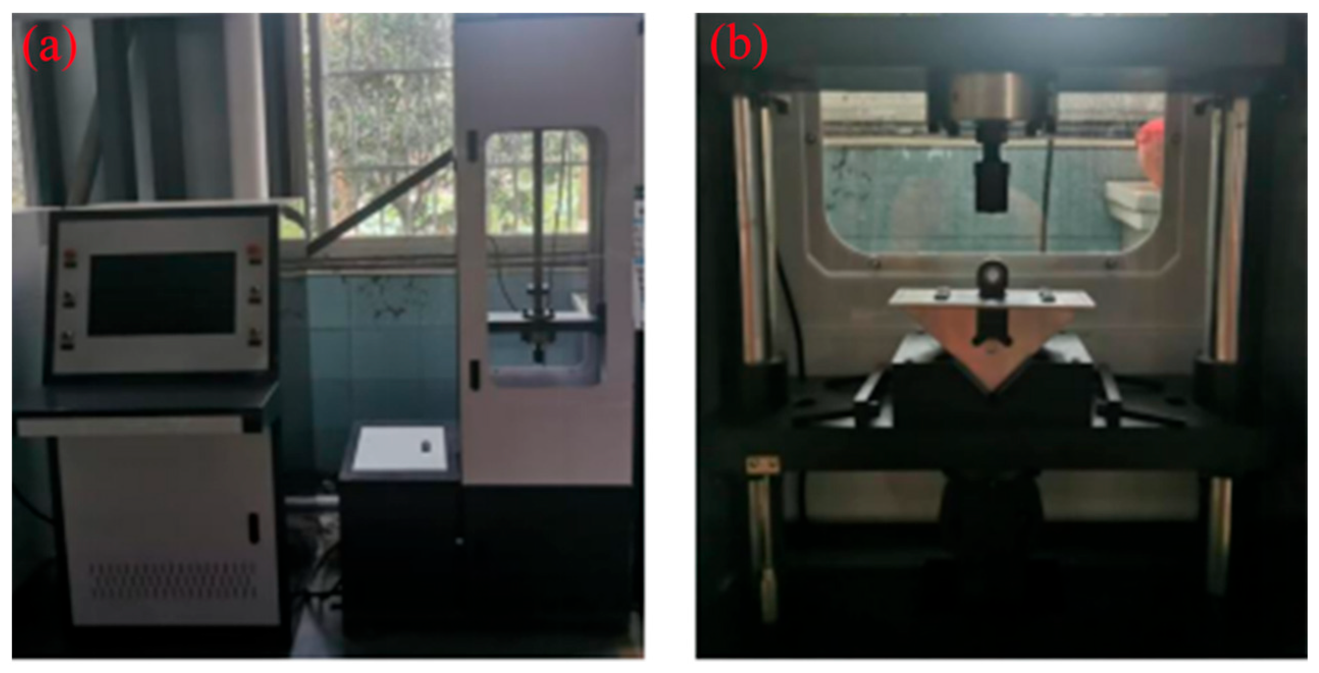
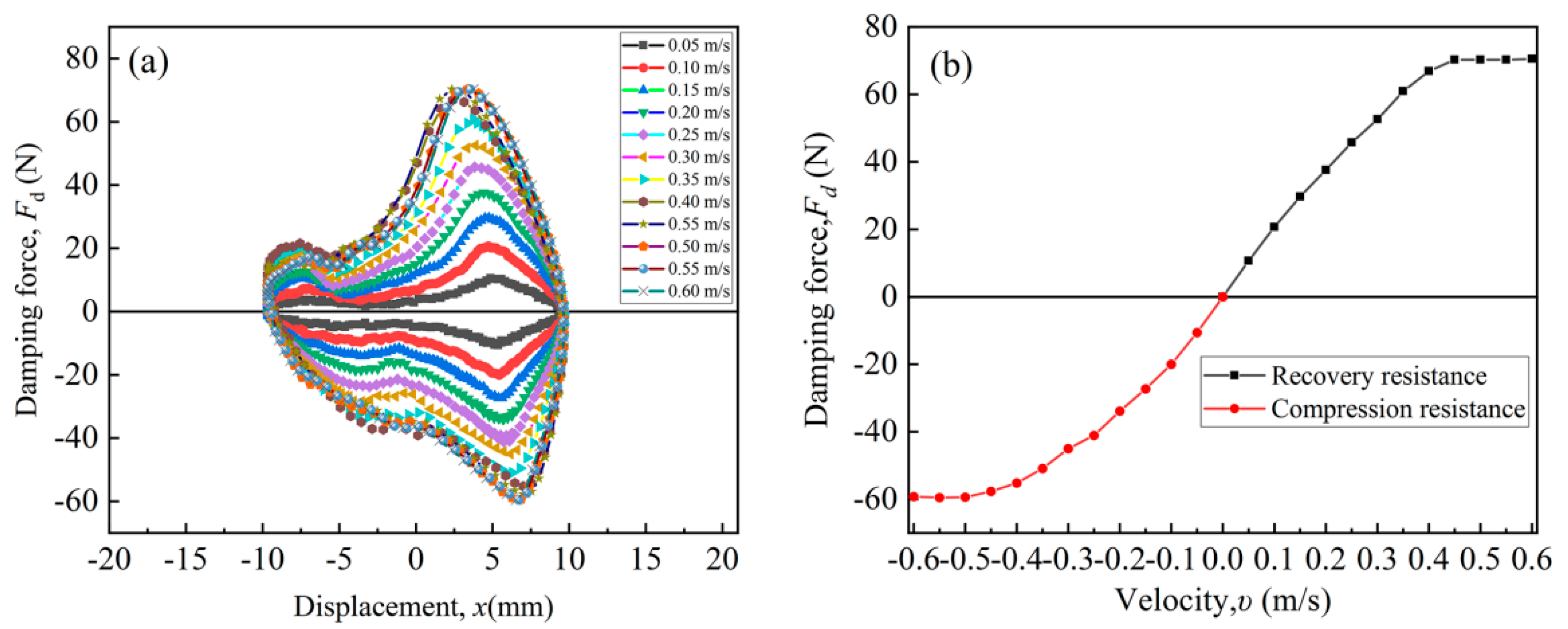
3.2. The Test and Calculation of Mechanical Properties of the MR Damper

Figure 3 shows the test bench of mechanical properties. On this test bench, the mechanical properties of the MR damper are tested by varying external excitations. The vibration displacement is set within the range of −10 to 10 mm, with vibration velocities ranging from 0.05 to 0.60 m/s. A computer system is employed to acquire data including damping force, displacement, and velocity.
Figure 4 presents the mechanical properties of the MR damper. As shown in Figure 4a, as the vibration displacement x varies from −10 mm to 10 mm, the damping force of the MR damper first increases and then decreases, and it reaches the maximum value when the x is 6 mm. Figure 4b demonstrates that the damping force gradually increases with increasing shear velocity, and approaches a maximum value of about 70 N when the shear velocity reaches 0.5 m/s. Based on these results, the damping coefficient k and stiffness coefficient c of the damper can be calculated using Equations (1) and (2) [31].
k = F d x
where k is the stiffness coefficient, Fd is the damping force, and x is the displacement of the damping plate.
c = F d υ
where c represents the damping coefficient, Fd denotes the damping force, and υ indicates the velocity of the damping. Based on the formula calculations, the stiffness coefficient k1 is calculated as 70 N/mm, and damping coefficient c1 is calculated as 0.12 N·s/mm, which are indispensable for the later subsequent damper simulation.

3.3. Simulation and Experiment of Vibration Reduction System of MR Damper

3.3.1. Simulation of Vibration Reduction Effect of MR Damper

ANSYS software (2021 version) was used to simulate the vibration reduction effects of MR dampers in the rotor system. The dimensional parameters of the 3D model of the rotor system are listed in Table 5. The simulation of three major components, such as the main shaft, the magnetorheological (MR) damper, and the supports, are included in the entire simulation of the rotor system. The material of the three components is selected as structural steel, and the density is 7850 kg/m3. For the simulation of the damper, the stiffness coefficient k1 calculated as 70 N/mm and damping coefficient c1 calculated as 0.12 N·s/mm need to be substituted. For the simulation of the fixed supports (as shown in Figure 2), the bearing constraint command was used, and to simplify analysis, the stiffness coefficient k2 and the damping coefficient c2 also needs to be substituted; the value of k2 is 65 N/mm and the value of c2 is 1 × 10⁻⁴ N·s/mm, which are selected according to the reference [32].

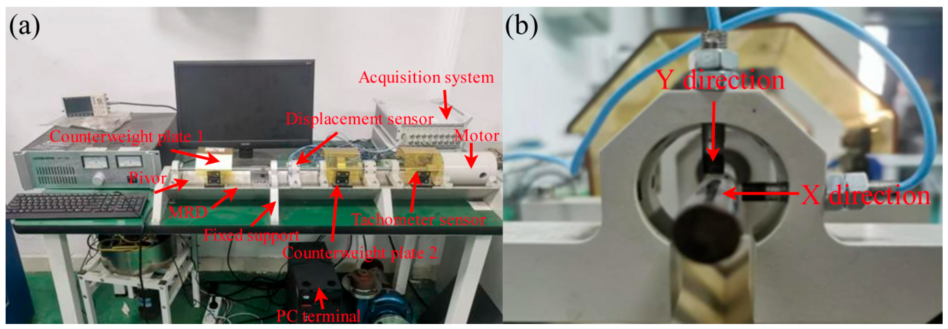
3.3.2. Experiment Procedures of Vibration Reduction Effect of MR Damper

The vibration reduction effect experiment of the MR damper was conducted with and without the MR damper using the rotor system, as shown in Figure 2. Before the experiment, the test system and sensors were first calibrated. After the calibration, the rotational speed of the shaft varied from 1000 rpm to 5000 rpm, at 400 rpm intervals. The sampling frequency was set at 1000 Hz with a sampling duration of 60 s. The shaft rotational speed, and shaft displacements in both X-direction and Y-direction, were recorded by the DHDAS.

4. Simulation and Experiment of Vibration Reduction Effect of Rotor System

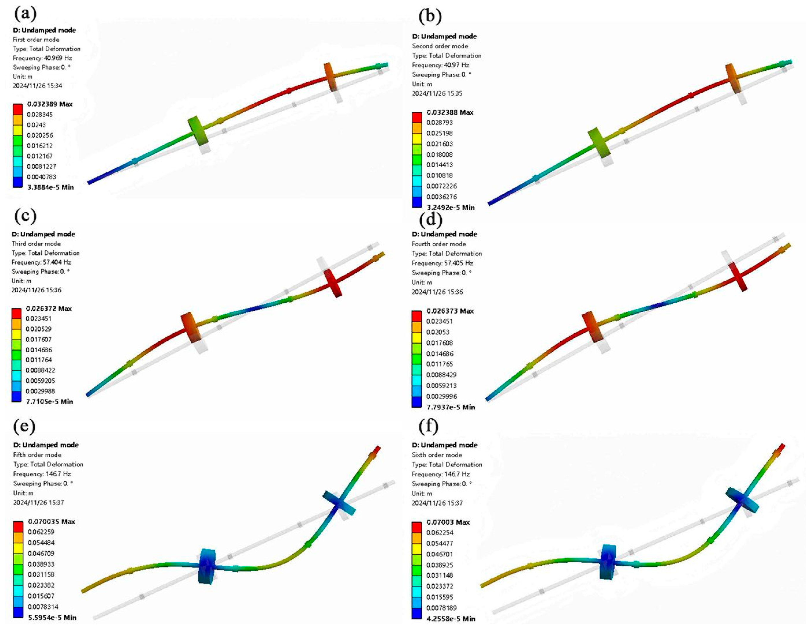
4.1. The Analysis of Simulation Results

Figure 5 and Figure 6 show the first six intrinsic frequencies and mode shapes of the rotor system without applying the MR damper and with applying the MR damper, respectively. The critical speeds and intrinsic frequencies of the rotor system with and without applying the MR damper are presented in Table 6. As shown in Figure 5 and Figure 6 and Table 6, after applying the MR damper, the intrinsic frequencies of the first four modes are higher than those without the MR damper, indicating the increase in the system’s stiffness and damping force; however, for the fifth and sixth modes are close to that without the MR damper, attributed to the MR damper introducing energy dissipation to the rotor system, thereby attenuating its vibrations [33]. Moreover, resonance occurs when the system’s rotational frequency approaches or coincides with its intrinsic frequency; the rotational speed of the shaft at this intrinsic frequency is the critical speed [34]. From Table 6, it is revealed that for the first four modes, these critical speeds all increase greatly, indicating the effectiveness of the MR damper in vibration reduction.

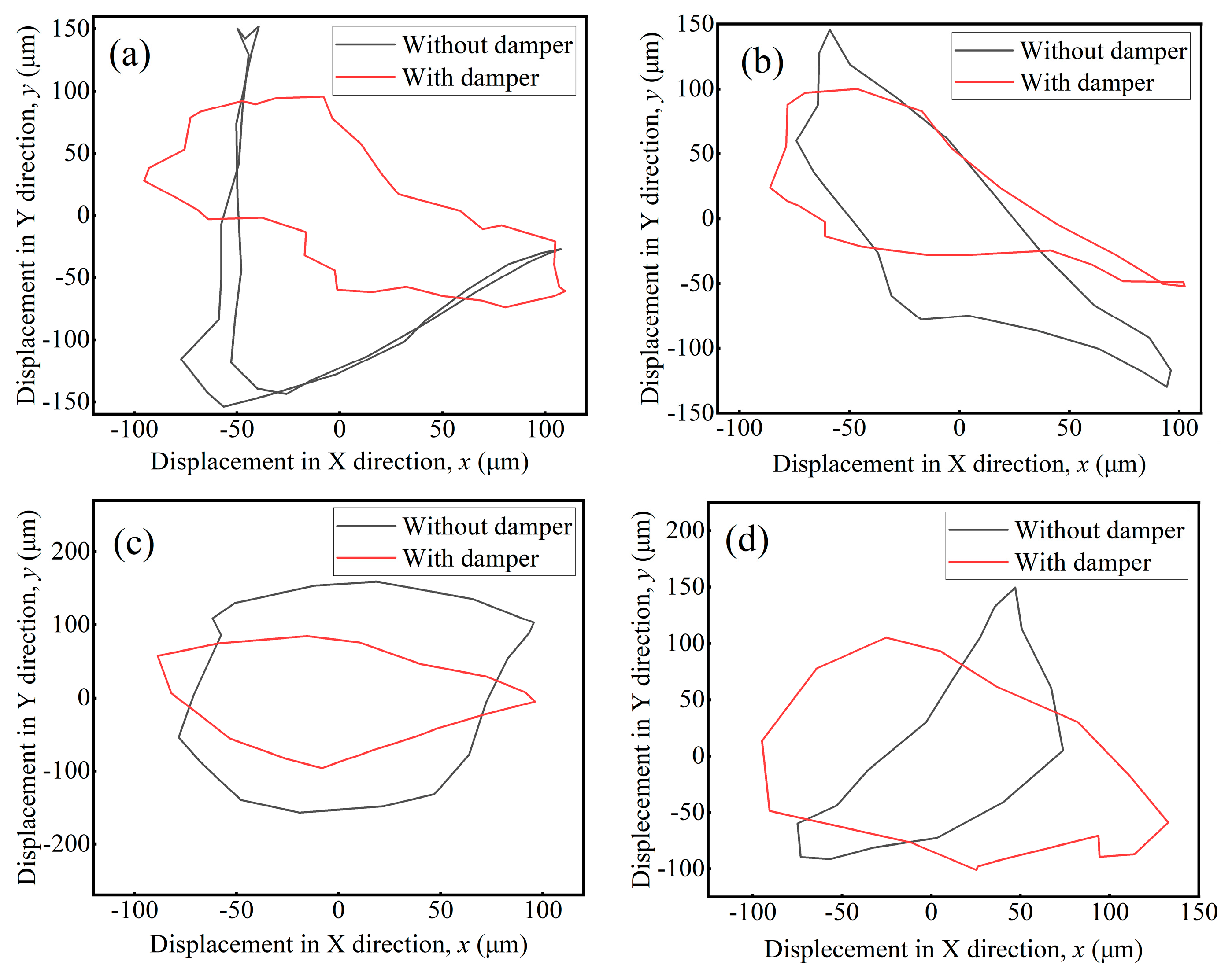
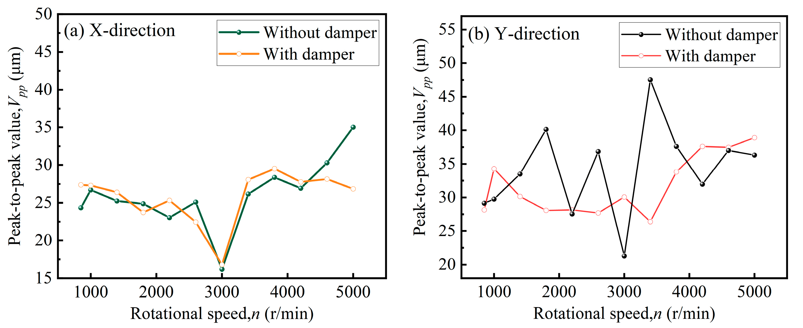
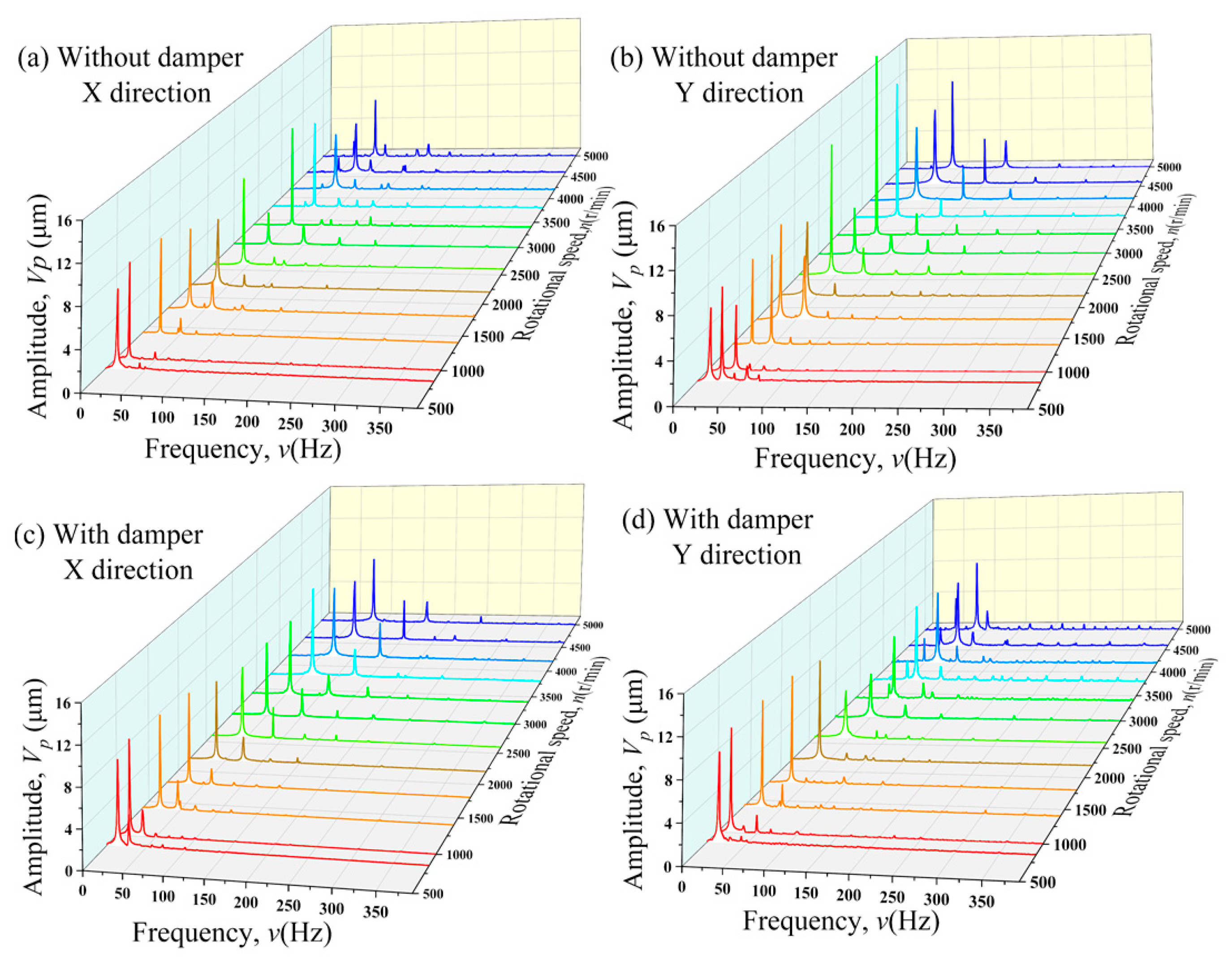
4.2. The Analysis of Experimental Results

Axis loci appear at different critical speeds of the rotor system, as shown in Figure 7. As shown in Figure 7, no significant difference in the peak-to-peak value was observed along the X-direction before and after applying the MR damper. All axis loci exhibit non-circular patterns, indicating the asymmetric stiffness in the elastic supports. However, the axis loci exhibit approximate circular shapes after applying the MR damper. Moreover, as shown in Figure 7a–c, a significant decrease trend of the peak-to-peak value was observed along the Y-direction before and after applying the MR damper, indicating that the vibration reduction effect of this magnetorheological (MR) damper is only effective in the Y-direction. As shown in Figure 7d, the Y-direction displacement has not changed significantly after applying the MR damper, attributed to the decrease in yield stress of MRF during vibration. It can be seen from the results that rotor system vibrations effectively reduce after applying the MR damper at critical speeds [35].
Figure 8 shows the peak-to-peak values of the rotor system at different speeds with and without applying the MR damper. As shown in Figure 8a, no significant difference in the peak-to-peak value was observed along the X-direction before and after applying the MR damper. In Figure 8b, as the rotational speed increases, it shows that the vibration peak-to-peak value has an obvious trend of significant decrease. The Y-direction displacement decreases from 40.13 μm to 28.08 μm after applying the MR damper at 1800 rpm. At 3400 rpm, the Y-direction displacement decreases from 47.5 μm to 26.4 μm, a 44.42% reduction. These results demonstrate that MR dampers can effectively suppress rotor system vibrations.
Figure 9 shows the waterfall plots of rotor vibration displacement at different speeds. As seen in Figure 9, during the rotor vibration at various rotational speeds, multiple vibration frequencies generate. Only the first two vibration frequencies are typically considered, and the amplitudes at other vibration frequencies are very small and it is usually not given key attention. The 1× frequency of rotor vibration is related to rotor unbalance, while the 2× frequency is associated with initial shaft bending [36]. By comparing Figure 9a,c, it can be seen that the vibration frequency characteristics in the X-direction show no significant changes after applying the damper. By comparing Figure 9b,d, it can be seen that vibration displacement at 1× frequency decreases from 9.98 μm to 3.02 μm after applying the MR damper, representing a 69.74% reduction, in the Y-direction, at 2600 rpm. The vibration displacement at 1× frequency decreases from more than 11.89 μm to 4.08 μm after applying the MR damper, representing a 65.69% reduction, in the Y-direction, at 3200 rpm. Overall, the amplitude at 1× frequency becomes smoother than without the MR damper. In addition, the amplitude at 2× frequency also reduced significantly, especially in the speed range of 850–1800 r/min. These findings indicate that MR damper effectively reduces vibrations caused by rotor unbalance and initial shaft bending, especially in the Y-direction.

5. Conclusions

In the paper, a MR damper with multi-layered permanent magnets was designed. The mechanical properties of the MR damper were obtained through testing and calculation. The stiffness coefficient k1 is calculated as 70 N/mm, the damping coefficient c1 is calculated as 0.12 N·s/mm. The simulation results show that the critical speeds all increase greatly for the first four modes. The experimental results show that the Y-direction displacement decreases from 40.13 μm to 28.08 μm at 1800 rpm and decreases from 47.5 μm to 26.4 μm at 3400 rpm after applying the MR damper. The vibration displacement at 1× frequency shows a 69.74% reduction at 2600 rpm and a 65.69% reduction at 3200 rpm in the Y-direction after applying the MR damper. Both simulation and experimental results demonstrate the effectiveness of the multi-layered permanent-magnet MR damper. Moreover, the layered permanent magnet structure demonstrates simplicity, safety, and reliability. The design of this layered permanent-magnet MR damper provides important theoretical foundation and practical value for spindle vibration control strategies.

Author Contributions

Conceptualization, F.C.; investigation, Q.G., Y.L., Y.D. and Y.X.; supervision, N.Z. and W.L. All authors have read and agreed to the published version of the manuscript.

Funding

This research was funded by the Regional Joint Fund for Innovative Development (grant no. U23A20669) and the Xihua University Science and Technology Innovation Competition Project for Postgraduate Students (grant no. YK20240214).

Data Availability Statement

Data available on request due to restrictions of privacy.

Conflicts of Interest

The authors declare no conflicts of interest.

References

  1. Wei, Y.; Ran, X.; Sun, T.; Liu, S.; Zhang, H.; Zhao, D. Dynamic characteristics analysis of a vertical Jeffcott rotor-brush seal system. J. Chin. Inst. Eng. 2022, 45, 245–254. [Google Scholar] [CrossRef]
  2. Li, W.; Li, Z.; Han, W.; Wang, Y.; Zhao, J.; Zhou, J. Morphologic transformation of ferrofluid during micropump driving under field control. Ann. N. Y. Acad. Sci. 2025, 1543, 194–203. [Google Scholar] [CrossRef] [PubMed]
  3. Al-Obaidi, A.R.; Alhamid, J. Analyses of the transient turbulence flow in a 3D impeller axial pump using Novel vibration signals and Inner dynamic simulation techniques. Flow Meas. Instrum. 2025, 102, 102779. [Google Scholar] [CrossRef]
  4. Hu, G.; Wu, L.; Deng, Y.; Yu, L.; Li, G. Optimal design and performance analysis of magnetorheological damper based on multiphysics coupling model. J. Magn. Magn. Mater. 2022, 558, 169527. [Google Scholar] [CrossRef]
  5. Wang, Z.; Liu, C.; Zheng, X.; Zhao, L.; Qiu, Y. Advancements in Semi-Active Automotive Suspension Systems with Magnetorheological Dampers: A Review. Appl. Sci. 2024, 14, 7866. [Google Scholar] [CrossRef]
  6. Hou, S.J.; Gong, J.L.; Wang, G.Y.; Bai, X.F. Experimental and simulation study on the temperature of bone drilled holes with axial low-frequency vibration. Mach. Des. Manuf. 2023, 6, 114–118. [Google Scholar]
  7. Song, S.; Luo, Y.; Ren, H.; Wang, Y.; Luo, J. Study on the microscopic model of magnetorheological fluids of three magnetic particles with different diameters. J. Magn. Magn. Mater. 2022, 564, 169854. [Google Scholar] [CrossRef]
  8. Pei, P.; Peng, Y. Constitutive modeling of magnetorheological fluids: A review. J. Magn. Magn. Mater. 2022, 550, 169076. [Google Scholar] [CrossRef]
  9. Marins, J.A.; Plachý, T.; Kuzhir, P. Iron–sepiolite magnetorheological fluids with improved performances. J. Rheol. 2019, 63, 125–139. [Google Scholar] [CrossRef]
  10. Rahman, M.; Ong, Z.C.; Julai, S.; Ferdaus, M.; Ahamed, R. A review of advances in magnetorheological dampers: Their design optimization and applications. J. Zhejiang Univ. A 2017, 18, 991–1010. [Google Scholar] [CrossRef]
  11. Chen, F.; Zhang, J.; Li, Z.; Yan, S.; Li, W.; Yan, Z.; Liu, X. Effect of the surface coating of carbonyl iron particles on the dispersion stability of magnetorheological fluid. Sci. Rep. 2024, 14, 1–15. [Google Scholar] [CrossRef]
  12. Chen, F.; Zhang, J.; Guo, Q.; Liu, Y.; Liu, X.; Ding, W.; Yan, S.; Yan, Z.; Li, Z. Carbonyl Iron Particles’ Enhanced Coating Effect Improves Magnetorheological Fluid’s Dispersion Stability. Materials 2024, 17, 4449. [Google Scholar] [CrossRef]
  13. Yang, G.; Pan, J.; Wang, D. A review on the magnetorheological materials and applications. Int. J. Appl. Electromagn. Mech. 2024, 75, 407–443. [Google Scholar] [CrossRef]
  14. Eshgarf, H.; Nadooshan, A.A.; Raisi, A. An overview on properties and applications of magnetorheological fluids: Dampers, batteries, valves and brakes. J. Energy Storage 2022, 50, 104648. [Google Scholar] [CrossRef]
  15. Li, W.; Li, Z.; Han, W.; Li, D.; Yan, S.; Zhou, J. Study of the Flow Characteristics of Pumped Media in the Confined Morphology of a Ferrofluid Pump with Annular Microscale Constraints. J. Fluids Eng. 2024, 147, 1–31. [Google Scholar] [CrossRef]
  16. Lu, M.; Yang, Y.; Lin, J.; Du, Y. Research progress of magnetorheological polishing technology: A review. Adv. Manuf. 2024, 1–37. [Google Scholar] [CrossRef]
  17. Li, W.; Li, Z.; Qin, Z.; Yan, S.; Wang, Z.; Peng, S. Influence of the solution pH on the design of a hydro-mechanical magneto-hydraulic sealing device. Eng. Fail. Anal. 2022, 135, 106091. [Google Scholar] [CrossRef]
  18. Oh, J.-S.; Sohn, J.W.; Choi, S.-B. Applications of Magnetorheological Fluid Actuator to Multi-DOF Systems: State-of-the-Art from 2015 to 2021. Actuators 2022, 11, 44. [Google Scholar] [CrossRef]
  19. Aziz, M.A.; Aminossadati, S.M. State-of-the-art developments of bypass Magnetorheological (MR) dampers: A review. Korea-Aust. Rheol. J. 2021, 33, 225–249. [Google Scholar] [CrossRef]
  20. Chen, A.; Liu, D.; Zhu, P. Progress in the study of nonlinear vibration of rotor system. J. Xiangtan Stitute Min. 1999, 2, 59–65. [Google Scholar]
  21. Wang, J.; Meng, G. Experimental study of magnetorheological fluid dampers for rotor vibration control. J. Huazhong Univ. Sci. Technol. Intrinsic Sci. Ed. 2001, 29, 3. [Google Scholar]
  22. Zhao, Q.; Zhao, J.Y.; Zhang, N. Modeling and control of vehicle dual magnetorheological damping seat suspension. J. Chongqing Univ. Technol. Intrinsic Sci. 2018, 32, 37–42. [Google Scholar]
  23. Zhang, L.; Tang, H.; Sun, T.; Yu, J.; Li, Z.; Wang, X. Vibration characteristics analysis of shaft system for bulb hydroelectric generating unit based on magnetorheological fluid damper. Chaos Solitons Fractals 2022, 163, 112559. [Google Scholar] [CrossRef]
  24. Hu, G.; Liu, F.; Xie, Z.; Xu, M. Design, analysis, and experimental evaluation of a double coil magnetorheological fluid damper. Shock. Vib. 2016, 1, 4184726. [Google Scholar] [CrossRef]
  25. Tae-Hoon, L.; Choi, S.-K. On the response time of a new permanent magnet based magnetorheological damper: Experimental investigation. Smart Mater. Struct. 2018, 28, 14001. [Google Scholar]
  26. Wang, J.; Liu, Y.; Qin, Z.; Ma, L.; Chu, F. Nonlinear characteristic investigation of magnetorheological damper-rotor system with local nonline-arity. Chin. J. Aeronaut. 2023, 36, 111–126. [Google Scholar]
  27. Ma, L.; Wang, J.; Li, C. Vibration suppression of a rotor system with a nonlinear MR damper. Arch. Appl. Mech. 2021, 91, 4053–4068. [Google Scholar] [CrossRef]
  28. Liu, P.; Ma, L.; Bo, W.; Wang, Z. Study on new type of permanent magnet magnetorheological damper for inclined cable and its parameter optimization. Bridge Constr. 2018, 48, 51–55. [Google Scholar]
  29. Kim, W.H.; Park, J.H.; Kaluvan, S.; Lee, Y.-S.; Choi, S.-B. A novel type of tunable magnetorheological dampers operated by permanent magnets. Sens. Actuators A Phys. 2017, 255, 104–117. [Google Scholar] [CrossRef]
  30. Khedkar, Y.M.; Bhat, S.; Adarsha, H. Fabrication and Testing of Modified Magnetorheological Damper Fitted with External Permanent Magnet Assembly. Int. J. Mech. Eng. Robot. Res. 2022, 11, 215–226. [Google Scholar] [CrossRef]
  31. Duan, Y.; Ni, Y.Q.; Zhang, H.F.B., Jr.; Ko, J.M.; Fang, Y. Design formulas for vibration control of taut cables using passive MR dampers. Smart Struct. Syst. Int. J. 2019, 23, 521–536. [Google Scholar]
  32. Hu, W.; Cheng, L.; Xi, L. Dynamic balance design and modal analysis of scroll compressor drive system. Model. Simul. 2023, 12, 524. [Google Scholar]
  33. Aziz, M.A.; Mohtasim, S.M.; Ahammed, R. State-of-the-art recent developments of large magnetorheological (MR) dampers: A review. Korea-Aust. Rheol. J. 2022, 34, 105–136. [Google Scholar] [CrossRef]
  34. Yao, D.K.; Zou, J.X.; Zhao, S.S. Effect of stiffness on shafting stability of Three Gorges Hydropower Generator Set. Power Stn. Syst. Eng. 2005, 21, 3. [Google Scholar]
  35. Qian, R.; Wang, G.; Jiang, M.; Zhang, Y.; Zhai, R.; Wang, W. Frequency-Dependent Bouc–Wen Modeling of Magnetorheological Damper Using Harmonic Balance Approach. Actuators 2024, 13, 297. [Google Scholar] [CrossRef]
  36. Zhang, G.C.; Wang, J.; Ma, L.; Li, C.H. Research on dynamic characteristics of rotor-MRD system under friction fault. Mech. Des. Manuf. 2021, 1, 210–215. [Google Scholar]
Figure 1. The MR damper: (a) the structural diagram, (b) the physical diagram.
Actuators 14 00271 g001
Figure 2. The schematic diagram of vibration reduction system of MR damper: (a) composition and structure, (b) partial enlarged drawing.
Actuators 14 00271 g002
Figure 3. The test bench of mechanical properties: (a) test bench, (b) fixture.
Actuators 14 00271 g003
Figure 4. The mechanical properties of the MR damper: (a) the force–displacement curve, (b) the force–velocity curve.
Actuators 14 00271 g004
Figure 5. The intrinsic frequency and vibration pattern of the first six orders of the rotor system without applying the MR damper: (a) first order, (b) second order, (c) third order, (d) fourth order, (e) fifth order, (f) sixth order.
Actuators 14 00271 g005
Figure 6. The intrinsic frequency and vibration pattern of the first six orders of the rotor system with applying the MR damper: (a) first order, (b) second order, (c) third order, (d) fourth order, (e) fifth order, (f) sixth order.
Actuators 14 00271 g006
Figure 7. Axis loci at different critical speeds of the rotor system: (a) 1800 rpm, (b) 2600 rpm, (c) 3400 rpm, (d) 3800 rpm.
Actuators 14 00271 g007
Figure 8. Peak–peak value of rotor system vibration at different speeds: (a) sensor X-direction, (b) sensor Y-direction.
Actuators 14 00271 g008
Figure 9. Waterfall diagram of rotor vibration displacement at different speeds: (a) X-direction without MR damper, (b) Y-direction without MR damper, (c) X-direction with applying MR damper, and (d) Y-direction with applying MR damper.
Actuators 14 00271 g009
Table 1. The different damping systems and motor characteristic range.
Damper SystemDamping DeviceApplicable Motor Characteristic Range
Passive dampersHydraulic damperSize range 50–500 mm
Power range > 100 kW
Rubber ringSize range 1–500 mm
Power range 1–10 kW
Semi-active damperCurrent flow damperSize range 5–150 mm
Power range 1–100 kW
Active dampersPiezoelectric actuatorsSize range 5–200 mm
Power range < 1 kW
Hybrid dampersThe piezoelectric actuator is combined with the rubber ringThe size can be adjusted by the piezoelectric actuator and rubber ring
Power range > 100 kW
Table 2. Structural parameters of MR damper.
StructureParameters
Dynamic damping plateLength: 37.5 mm; width: 22 mm; thickness: 2 mm
Static damping plateLength: 27 mm; width: 28 mm; thickness: 2 mm
Permanent magnetLength: 24 mm; width: 33 mm; thickness: 5 mm
SeptumLength: 24 mm; width: 33 mm; thickness: 4 mm
BearingOuter diameter: 8.5 mm; inner diameter: 5 mm
Table 3. Performance parameters of MRF.
Physical QuantityParameters
Particle size5 μm
Mass fraction of particles60 wt.%
Density of coated CIP5.036 g/cm3
Zero-field viscosity (25 °C)19.47 Pa·s
Field-induced shear yield stress (175 kA/m, 25 °C, 1000 s−1)18.95 kPa
Table 4. The parameters of each component of the rotor system.
System DeviceParameters
PivotDiameter: 10 mm; length: 820 mm
Counterweight plate 1Diameter: 74 mm; thickness: 25 mm; mass: 500 g
Counterweight plate 2Diameter: 74 mm; thickness: 15 mm; mass; 800 g
MotorRotational speed: 0~10,000 r/min
Displacement sensorDiameter: 5 mm; sensitivity: −8 V/mm; range: 0~10,000 Hz
Tachometer sensorTest range: 1~20,000 r/min
Table 5. The dimensional parameters of the 3D model of the rotor system.
Character RadicalParameters
Spindle diameter10 mm
Spindle length820 mm
Counterweight disk diameter74 mm
Counterweight disk length5 mm
Table 6. Critical speed and intrinsic frequency of rotor system with or without MR damper.
VariableModal OrderRotate DirectionCritical Speed (rpm)Intrinsic Frequency (Hz)
Undamped1BW2452.540.969
2FW2463.740.970
3BW3437.757.404
4FW3450.857.405
5BW-146.700
6FW-146.700
Damping1BW3104.751.768
2FW3107.551.768
3BW3637.060.724
4FW3649.960.727
5BW-143.760
6FW-143.760
Disclaimer/Publisher’s Note: The statements, opinions and data contained in all publications are solely those of the individual author(s) and contributor(s) and not of MDPI and/or the editor(s). MDPI and/or the editor(s) disclaim responsibility for any injury to people or property resulting from any ideas, methods, instructions or products referred to in the content.

