1. Introduction
Large radio telescopes, as crucial instruments in modern astronomical observation, have their observation accuracy directly determining the depth and breadth of astronomical research [
1,
2,
3,
4]. In ultra-large radio telescope systems, active reflector technology enhances observational performance by real-time shape adjustment of the reflecting surface to compensate for environmental disturbances [
5,
6]. As core components of active reflector systems, actuators are responsible for precisely controlling the displacement of reflector elements, where their control accuracy and anti-interference capability are crucial to the overall observation performance.
Ultra-large radio telescope systems typically deploy numerous actuators operating in open-air environments with electromagnetic interference, mechanical vibrations, and temperature fluctuations, which significantly degrade control accuracy and system stability. Recent studies have extensively investigated actuator systems. Luo et al. [
7] developed a piezoelectric bending actuator using fuzzy logic algorithms to suppress first-order bending modes in annular truss structures, though neglecting nonlinear friction effects under complex dynamic loads. Jing et al. [
8] implemented a multi-objective control strategy for actuator coordination but omitted disturbance observation mechanisms, limiting anti-interference capabilities. Zhou et al. [
9] designed a novel displacement actuator, achieving 3.67 mm precision (standard deviation) through S-curve acceleration control, yet its adaptability to complex dynamic loads requires improvement. Deng et al. [
10] proposed an ultrasonic motor-driven micro-displacement actuator without considering disturbance impacts. Zhang et al. [
11] introduced an axiomatic design and multi-criteria decision-making method for actuator selection. Critical analysis reveals two persistent limitations in existing actuator control systems: insufficient disturbance observation and compensation mechanisms and inadequate energy efficiency optimization while maintaining precision and stability. These constraints severely hinder practical applications in complex environments.
Model Predictive Control (MPC) has been widely applied in the field of process control due to its predictive and optimization characteristics. Liu et al. [
12] proposed a Model Predictive Control (MPC)-based method for subway train speed tracking control, specifically addressing the complexity of constrained optimization in practical applications. However, this approach mainly targets single systems and lacks systematic compensation for multi-source disturbances. Wang et al. [
13] proposed an improved MPC controller based on fuzzy adaptive weight control to address issues in path tracking processes, but its scalability to high-dimensional systems is limited. Alcalá et al. [
14] employed Linear Parameter-Varying (LPV) theory for dynamic modeling and implemented an LPV Model Predictive Controller (LPV-MPC) that can be computed online, thereby reducing computational costs, but it is mainly suitable for scenarios with stable parameter variations. Lee et al. [
15] proposed a tube-based MPC method for the path tracking of autonomous articulated vehicles, which effectively improved the system’s robustness and path tracking accuracy under external disturbances. However, the real-time performance and computational complexity in large-scale systems have not been fully addressed. Radac et al. [
16] designed various controllers for the variable-speed operation of high-power wind turbines to achieve optimal and reliable operation, enhancing system performance and reliability, but the control accuracy and complexity under actual complex disturbances still require further trade-offs. Fernandez et al. [
17] proposed an MPC-based electric vehicle charging optimization method, achieving dynamic response to grid load and user demand, and improving urban energy management efficiency. However, the assumptions are relatively ideal and do not fully consider practical factors such as renewable energy. Hanover et al. [
18] proposed an L1 adaptive Nonlinear Model Predictive Control (L1-NMPC) method, which significantly improved the tracking accuracy and robustness of quadrotor systems under complex disturbances and parameter variations through online learning and real-time compensation for model uncertainties. However, this method mainly targets quadrotor UAVs, and the model structure differs from that of radio telescope actuator systems. Its real-time performance and adaptability in large-scale actuator arrays or higher-dimensional complex systems still need further verification. Li et al. [
19] proposed a speed-dependent active suspension MPC control method combined with road preview information, which simplifies online computation through adaptive filtering and look-up tables, but its adaptability in larger-scale systems or more complex working conditions still needs further verification.
In summary, although existing research has made certain progress in improving the control accuracy, robustness, and optimization performance of actuator systems, there are still common issues such as insufficient disturbance observation and compensation, and limited energy consumption optimization when facing complex disturbance environments such as those in ultra-large radio telescope actuator systems, making it difficult to meet the high requirements of practical engineering applications. Therefore, it is urgent to develop a new control method that can balance high accuracy, strong robustness, and energy consumption optimization.
To address the above issues, this paper proposes an Improved Model Predictive Control (IMPC) algorithm based on an extended state observer and systematically verifies it on the 500-m aperture spherical radio telescope digital twin experimental platform [
20]. The main contributions of this paper are as follows: 1. Aiming at the requirements of high accuracy and disturbance rejection for actuator systems in complex environments, an IMPC algorithm based on an extended state observer is proposed, which realizes real-time estimation and compensation of system states and external disturbances, significantly improving the control accuracy and robustness of the system. 2. By integrating a multi-objective optimization strategy, the proposed method effectively reduces energy consumption while ensuring high actuator accuracy and system stability, thus enhancing the engineering application value of the actuator system. 3. Based on the 500-m aperture spherical radio telescope digital twin experimental platform, comprehensive experiments were conducted on actuator control accuracy, disturbance rejection capability, load disturbance response, electrical constant disturbance, and energy consumption optimization, fully verifying the effectiveness and superiority of the proposed IMPC algorithm.
2. Actuator Control System Design
2.1. Overall System Architecture
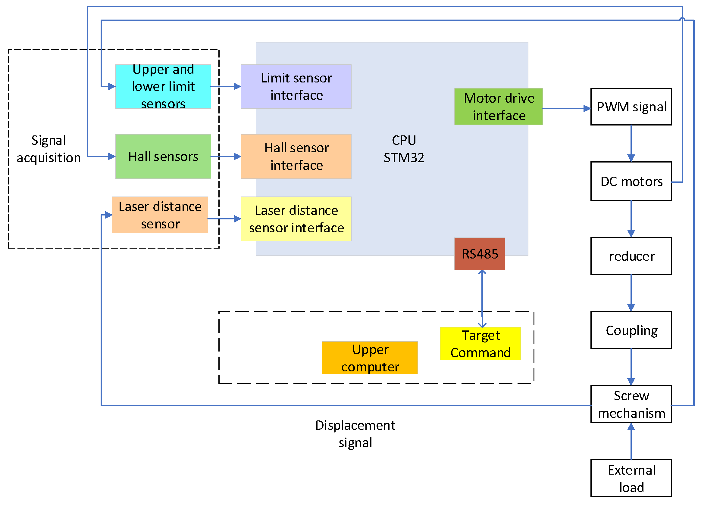
The actuator control system comprises a host computer, an STM32 controller, a brushless DC motor, a real-time ranging module, limit switches, and auxiliary circuits. As shown in
Figure 1, this system framework is designed to achieve precise displacement control for the actuators driving the 1:100 scaled 5-m active reflector of the Five-hundred-meter Aperture Spherical radio Telescope (FAST).
The host computer communicates with the STM32 controller via the RS485 bus, forming a closed-loop control architecture by integrating feedback from the real-time ranging module and limit switches. As the core processing unit, the STM32 controller receives control commands from the host computer through the RS485 interface and performs real-time processing of feedback signals. Based on target position commands, the controller generates PWM signals to drive the brushless DC motor while monitoring the motor’s rotational speed through Hall effect sensors, thereby providing reference data for system status monitoring.
Within the hardware architecture, the laser ranging sensor interfaces with the STM32 controller via USART to acquire precise real-time distance measurements of the target position. Limit switches detect boundary conditions to prevent operations beyond safe mechanical ranges. The PWM signals output from the STM32 drive the brushless DC motor, which converts rotational motion into linear displacement through a reducer and screw mechanism, achieving micron-level precision in positional adjustments.
2.2. Hardware Architecture
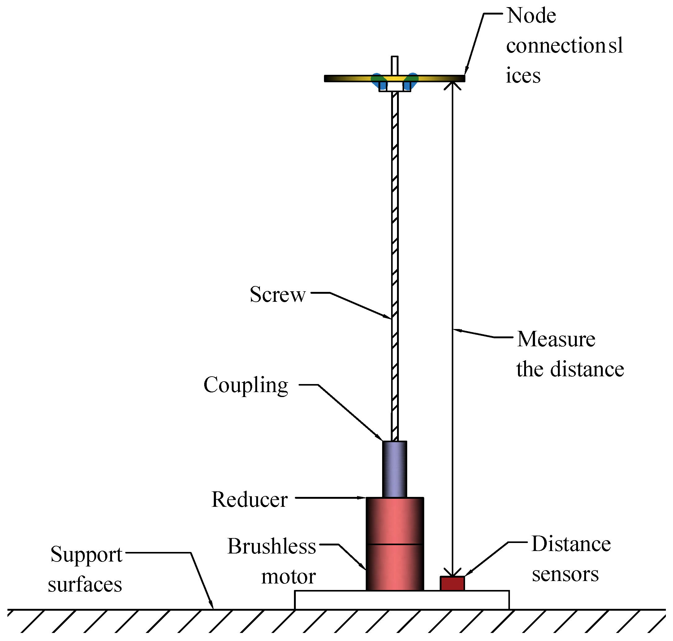
The actuator mainly consists of five components: a brushless DC motor, a gear reducer, a coupling, a screw drive mechanism, and a laser ranging sensor, as shown in
Figure 2. The brushless DC motor acts as the power source. Through the gear reducer with a reduction ratio of 45:1, it converts high-speed low-torque rotational motion into low-speed, high-torque output, effectively improving the system’s positioning accuracy and load capacity. The output shaft of the reducer is connected to the screw via the coupling. The screw has a lead of 1 mm, meaning that one full rotation of the screw results in 1 mm of linear displacement of the actuator.
Based on the gear ratio and screw lead, the linear displacement of the actuator per motor revolution can be calculated as:
where
represents the linear displacement,
P is the screw lead, and
i is the gear ratio.
This design enables the system to achieve micrometer-level positioning accuracy, fulfilling the requirements for precise adjustment of the active reflector surface. Additionally, limiters are integrated to prevent the actuator from exceeding its designed travel range, thereby ensuring system safety.
To achieve high-precision position and speed detection, the system uses a laser displacement sensor for position feedback. The sensor operates at a fixed frequency of 120 Hz, covers a measurement range from 0.07 mm to 500 mm, has a resolution of 0.01 mm, and a typical measurement accuracy of ±0.2 mm. After applying moving average filtering, the measurement accuracy can reach 0.05 mm, which meets the control requirements. The motor speed is detected via the FG signal, which is isolated by an optocoupler and then input to the STM32 capture port for real-time speed measurement.
Controller and Communication System
The core processor of the control system adopts an STM32 microcontroller with a clock frequency of 168 MHz, ensuring sufficient computational power to support complex control algorithms and real-time data processing. Timer TIM1 is configured in PWM mode, outputting a 20 kHz PWM signal with a resolution of 1000 steps, enabling high-precision motor speed regulation. Timer TIM2 is set to input capture mode to measure the frequency of the motor’s FG signal, providing accurate feedback data for closed-loop speed control. Communication between the microcontroller and the laser ranging module utilizes the USART interface. USART2 is configured at 230,400 bps for high-speed data exchange with the laser ranging module, while limit switches connected via GPIO inputs provide travel limit detection.
The microcontroller communicates with the host computer via RS485. RS485 employs differential signal transmission, offering strong noise immunity and extended transmission distances, making it suitable for experimental platforms. The system uses the MAX485 chip to convert UART signals to RS485 signals. The hardware connections are shown in
Figure 3. The communication protocol adopts Modbus RTU [
21] and supports common function codes; specific parameters are shown in
Table 1.
The communication protocol adopts the Modbus RTU protocol, which is widely used in industrial control applications and provides excellent compatibility and reliability.
Through the register mapping mechanism, the host computer can read system status and set control parameters, enabling remote control and monitoring of the actuator. The system is designed with timeout detection, CRC verification, and communication retry mechanisms to ensure stable communication. Register mapping is used to achieve read and write operations on parameters such as the actuator’s position and speed. The system adopts conventional power management and filtering protection measures to ensure reliability.
2.3. Software Design
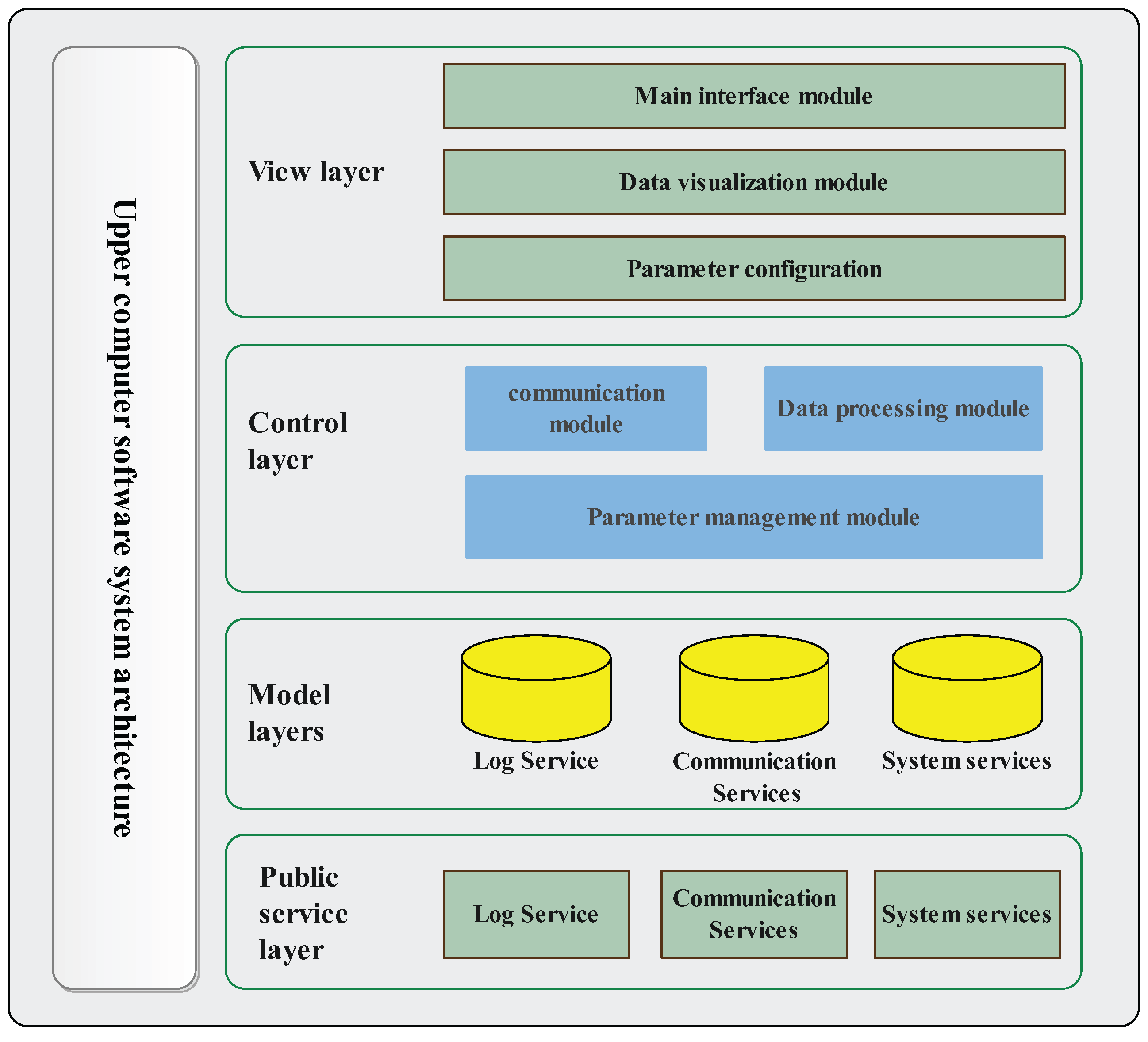
The host computer software was developed using Python version 3.12 and the PyQt5 framework version 5.15 to construct the interface and provide intuitive human–machine interaction.Following the MVC (Model-View-Controller) architecture [
22], the software achieves the decoupling of data models, views, and controller logic. As shown in
Figure 4, the system architecture comprises four layers: the view layer, controller layer, model layer, and shared service layer.
The view layer serves as the entry point for user interaction, integrating functional modules for main interface operations, data visualization, and parameter configuration. The main interface module enables user command input through graphical controls. The data visualization module dynamically displays equipment status via real-time curves and tables, supporting historical data playback. The parameter configuration module provides an interface for flexible algorithm tuning, allowing users to optimize control logic based on experimental requirements.
The controller layer acts as the core logic processing unit, encompassing three modules: communication management, data processing, and parameter management. The communication module interacts with the lower-level controller via the RS485 bus protocol, employing Modbus RTU for command transmission and data acquisition to ensure millisecond-level real-time communication. The data processing module performs filtering, noise reduction, and coordinate conversion on raw signals. The parameter management module dynamically adjusts IMPC control parameters based on real-time feedback to enhance closed-loop control precision.
The model layer handles data storage and algorithm configuration, comprising device data management, database storage, and model loading modules. The device data module records equipment status in structured formats with timestamp labeling. The database module supports CSV file import/export operations. The model loading module enables the rapid deployment of pre-trained control models, facilitating the validation of multiple algorithm strategies.
The shared service layer provides foundational support through logging, communication protocol management, and system monitoring. The logging service documents critical operational events and fault alerts with time/type-based retrieval capabilities. The communication service encapsulates TCP/IP and serial port protocols for cross-platform compatibility. The system monitoring module tracks CPU/memory utilization in real-time to ensure software stability.
3. Control Algorithm Design
This section presents the design and optimization process of the actuator control algorithm based on Model Predictive Control (MPC). The procedure begins with the mathematical modeling of the system to accurately describe its dynamic characteristics and the effects of external disturbances. Building on this foundation, a controller is designed to meet the system’s performance requirements. The core focus of the controller design includes three aspects: model establishment, controller design and optimization, and stability analysis.
First, a state-space model is developed to characterize the actuator’s physical behavior, explicitly defining its dynamic response and controlled variables. Second, leveraging the concept of an Extended State Observer (ESO), a controller is designed to enable real-time disturbance estimation and compensation. Finally, theoretical analysis is conducted to validate the controller’s stability and robustness, establishing a theoretical foundation for subsequent experimental validation.
3.1. Actuator Modeling
The actuator primarily consists of a brushless DC motor, a gear reducer, a lead screw mechanism, and a position sensor. The system’s physical model comprises two subsystems: electrical and mechanical. External disturbances mainly originate from electrical system uncertainties and mechanical system nonlinearities. These disturbances significantly impact the system’s dynamic characteristics and must be accounted for in the model. Electrical equations:
In this formula, i represents the motor current, u is the input voltage, is the back electromotive force constant, is the angular velocity of the motor, and L and R are the motor’s inductance and resistance, respectively. The electrical disturbance primarily arises from fluctuations in the input voltage and variations in the motor’s back electromotive force .
In this equation, J is the moment of inertia, B is the damping coefficient, is the torque constant, and is the load torque. The mechanical disturbance is caused by variations in the load torque , changes in the damping coefficient , and fluctuations in the moment of inertia .
The positional relationship is described by the gear ratio
n, which defines the relationship between the motor angular velocity
and the output angular displacement
:
This relationship is used to define the dynamic characteristics of the state variable and is reflected in the state-space model.
To construct the state-space model, the motor current, angular velocity
, and the angular displacement
at the output of the gear reducer are selected as state variables,
. With the control input
u and the system output
, the model can comprehensively describe the electrical and mechanical dynamic characteristics of the system. Combining Equations (2)–(5), the state-space model of the system is expressed as:
The state-space model represents the electrical dynamics, mechanical dynamics, and external disturbances of the system, providing a mathematical foundation for subsequent controller design. The matrices
A,
B,
C, and
E are defined as follows:
To facilitate the implementation of digital controllers, the zero-order hold method is used to discretize the continuous system [
23]. With a sampling period of
, the discretized state-space model is obtained as:
where:
, , and are the system matrices after discretization, representing the control matrix and disturbance matrix, respectively. denotes the sampling period.
3.2. Control Algorithm Design
3.2.1. Extended State Observer Design
In order to estimate the system states and external disturbances in real time, an extended state observer is designed. The observer is based on the state-space model: Equations (10) and (11). By introducing the extended state vector
, the disturbance is regarded as an additional state variable of the system for estimation, and the extended state-space model is constructed. Here,
, where
represents electrical disturbance and
represents mechanical disturbance. The disturbance is estimated as an extended state variable, and the extended state vector is constructed as follows:
. The extended state-space model is expressed as:
where:
where
is the reference input and
is the system output. For multiple disturbances, a state variable is introduced for each disturbance to ensure that the dimension of the extended state space is consistent with the number of disturbances. The disturbance state adopts a random walk model:
To estimate the extended state
, which includes the system states and disturbances, a Luenberger observer based on the extended state-space model is designed [
24].
where
is the estimated extended state,
is the estimated output, and
L is the observer gain matrix.
The design of the observer gain
L is based on pole placement, ensuring that the eigenvalues of the observer converge faster than the system dynamics [
25]. By solving the following optimization problem,
L is obtained:
where
is the convergence rate parameter, set to
.
3.2.2. Multiobjective Optimization
Compared with the traditional MPC method, the IMPC (Improved Model Predictive Control) proposed in this paper expands and innovates the optimization objectives and control strategies. Standard MPC usually adopts the following single-objective quadratic performance index, which mainly focuses on the tracking error and control performance of the system:
where
Q and
R are fixed weighting matrices,
is the predicted state,
is the reference trajectory, and
is the control input. This method only considers single-objective performance, and it is difficult for it to meet the diverse performance requirements of practical systems.
The actuator system needs to meet a number of performance indexes, such as tracking accuracy, dynamic performance, and energy consumption during operation. Therefore, a multi-objective optimization framework is set up to achieve the balanced optimization of each performance index through weight configuration. A multi-objective optimization function is designed.
where
is the reference trajectory and
Q,
R, and
S are the weighting matrices for position error, control input, and control increment, respectively.
is the control horizon, and
is the control increment.
Three real-time performance indices are defined as tracking error
, control input
, and control increment
:
The weights are dynamically adjusted based on the deviation of the real-time performance indices from their reference values:
where
,
,
are reference performance indices and
,
,
are adjustment step parameters.
In order to avoid the optimization result being unbalanced due to the weight being too large or too small, the adjusted weight is normalized:
In each control period, based on the current situation and performance indices, the weighting matrices Q, R, and S are updated in real time. Through the above adaptive adjustment strategy, the system dynamically balances the priorities of each performance index to achieve multi-objective optimal control.
3.2.3. IMPC Control Strategy
After the design of the IMPC algorithm is completed, in order to ensure the feasibility and effectiveness of the control strategy in the actual system, it is necessary to consider the inherent physical constraints of the actuator system. The key physical constraints in the system and their processing methods in the control algorithm will be analyzed below.
Considering the physical constraints of the actuator, the optimization problem needs to satisfy the following constraints:
The optimization problem is transformed into a standard Quadratic Programming (QP) problem [
26], with the objective function given by:
Subject to:
where
H is a positive definite matrix derived from the weighting matrices
Q,
R, and
S in the objective function;
G and
h define the input and state constraints;
and
b define the equality constraints.
In this study, the OSQP solver is selected, which supports sparse matrix optimization, has high computational efficiency, and is suitable for real-time control [
27]. By solving the above optimization problem using the QP method, the optimal control sequence
is obtained. According to the receding horizon optimization principle, only the first control input
is applied to the system.
It should be noted that the decision variable of the IMPC optimization problem is the control input sequence u over a future time horizon, rather than directly solving for the state feedback gain matrix K. However, in subsequent theoretical analysis and stability proofs, the optimal control law is often approximated as a linear feedback form for convenience in describing the structure of the closed-loop system. This equivalent linear feedback assumption provides a theoretical basis for the subsequent system performance analysis.
3.3. Algorithm Performance Analysis
The stability of the IMPC algorithm is ensured through the design of the prediction horizon
and the weighting matrices
Q,
R, and
S. The decrease of the Lyapunov function
is the key to system stability. The Lyapunov function for the closed-loop system is constructed as [
28,
29]:
where
P is a positive definite matrix used to balance the system state energy. The state update equation for the closed-loop system in the IMPC algorithm is:
where
is the state matrix of the extended state-space model,
is the control input matrix, and
K is the gain matrix of the equivalent linear feedback.
To ensure the stability of the closed-loop system, the following condition must be satisfied:
Substituting Equation (
33) into Equation (
34), we obtain:
To satisfy Equation (
35), a positive definite matrix
Q is introduced, such that:
If Q is positive definite, the closed-loop system will gradually stabilize. The design of the weighting matrices Q, R, and S in the optimization objective function ensures the rationality of the control gain K. Theoretical analysis shows that, when and the weighting matrices are positive definite, the closed-loop system satisfies the Lyapunov stability condition. Under the condition that the prediction horizon and the weighting matrices are positive definite, the IMPC algorithm ensures that the closed-loop system gradually stabilizes, effectively suppressing disturbances and ensuring control accuracy.
3.4. Algorithm Implementation Process
The implementation flowchart of the IMPC algorithm is shown in
Figure 5, centered on closed-loop feedback. Through the collaborative operation of modules including state estimation, prediction model construction, optimization solving, and constraint handling, high-precision dynamic control is achieved.
In each control period k, the measured value of the system output is first obtained through sensors, and the extended state observer updates the estimated state based on this measurement. The updated state estimate, together with the reference trajectory , is input into the prediction model module to generate the predicted state sequence for steps ahead.
The optimization solver calculates the optimal control sequence according to the prediction model, objective function, and constraints. To improve real-time performance, the quadratic programming (QP) process utilizes sparse matrix operations and warm-start acceleration. Only the first control input is applied to the system, and the process is repeated in the next control period, thus achieving closed-loop feedback and high-precision dynamic control.
4. Experiments and Results Analysis
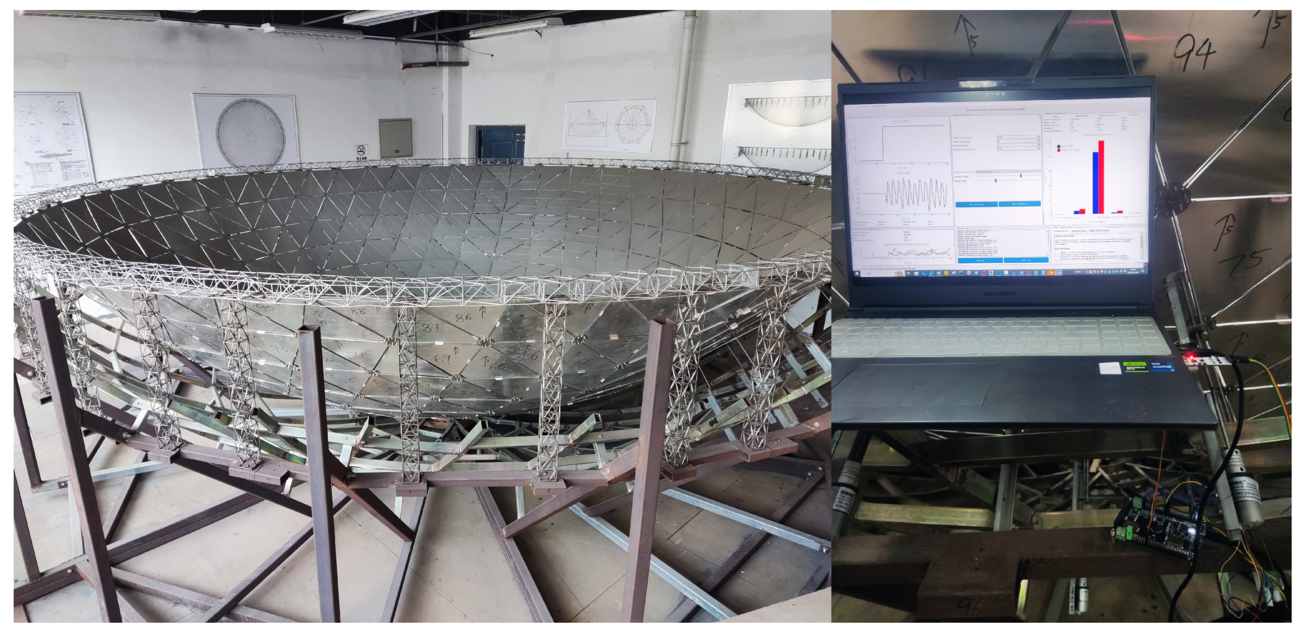
To comprehensively evaluate the control performance of the proposed IMPC algorithm in the actuator system, a series of experiments were designed and conducted, including control accuracy, disturbance rejection capability, dynamic response performance, and energy consumption optimization. The experimental platform is shown in
Figure 6, and a systematic comparative analysis was carried out with standard MPC, fuzzy control, and PID control methods. To ensure the fairness of the comparison among different control methods, the key hyperparameters of IMPC, MPC, fuzzy control, and PID controllers were systematically tuned. Specifically, the weight parameters and prediction horizons of IMPC and MPC were optimized using grid search, the rule base and membership functions of fuzzy control were adjusted through multiple rounds, and the proportional, integral, and derivative parameters of the PID controller were determined by the Ziegler–Nichols method and experimental fine-tuning. All controllers were tuned and tested on the same experimental platform and under the same working conditions to ensure optimal performance, thereby guaranteeing the objectivity and fairness of the experimental results. The main physical parameters of the actuator and the IMPC controller parameters are shown in
Table 2.
4.1. Control Accuracy Test and Analysis
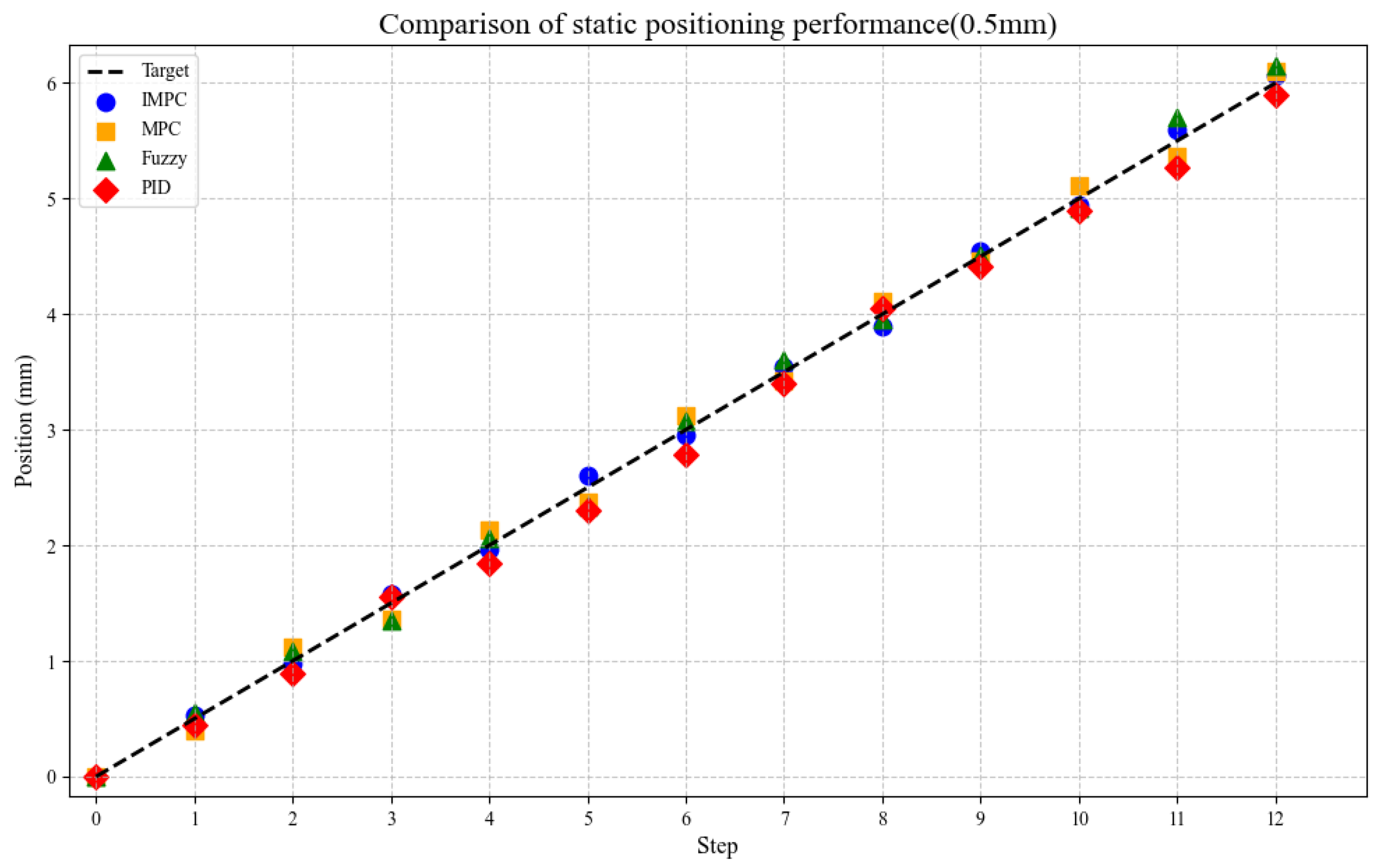
To evaluate the static positioning accuracy of the actuator at different target positions, the actuator moves with step sizes of 0.5 mm and 1 mm. A laser rangefinder sensor detects the output displacement for feedback and comparison with the target displacement. Each step size is tested 12 times, with recorded output positions compared against theoretical values, as shown in
Figure 7 and
Figure 8. Results demonstrate that IMPC achieves the smallest average positioning error of 0.10 mm, significantly outperforming other control strategies. In comparison, standard MPC, fuzzy control, and PID control exhibit positioning errors of 0.18 mm, 0.22 mm, and 0.24 mm, respectively.
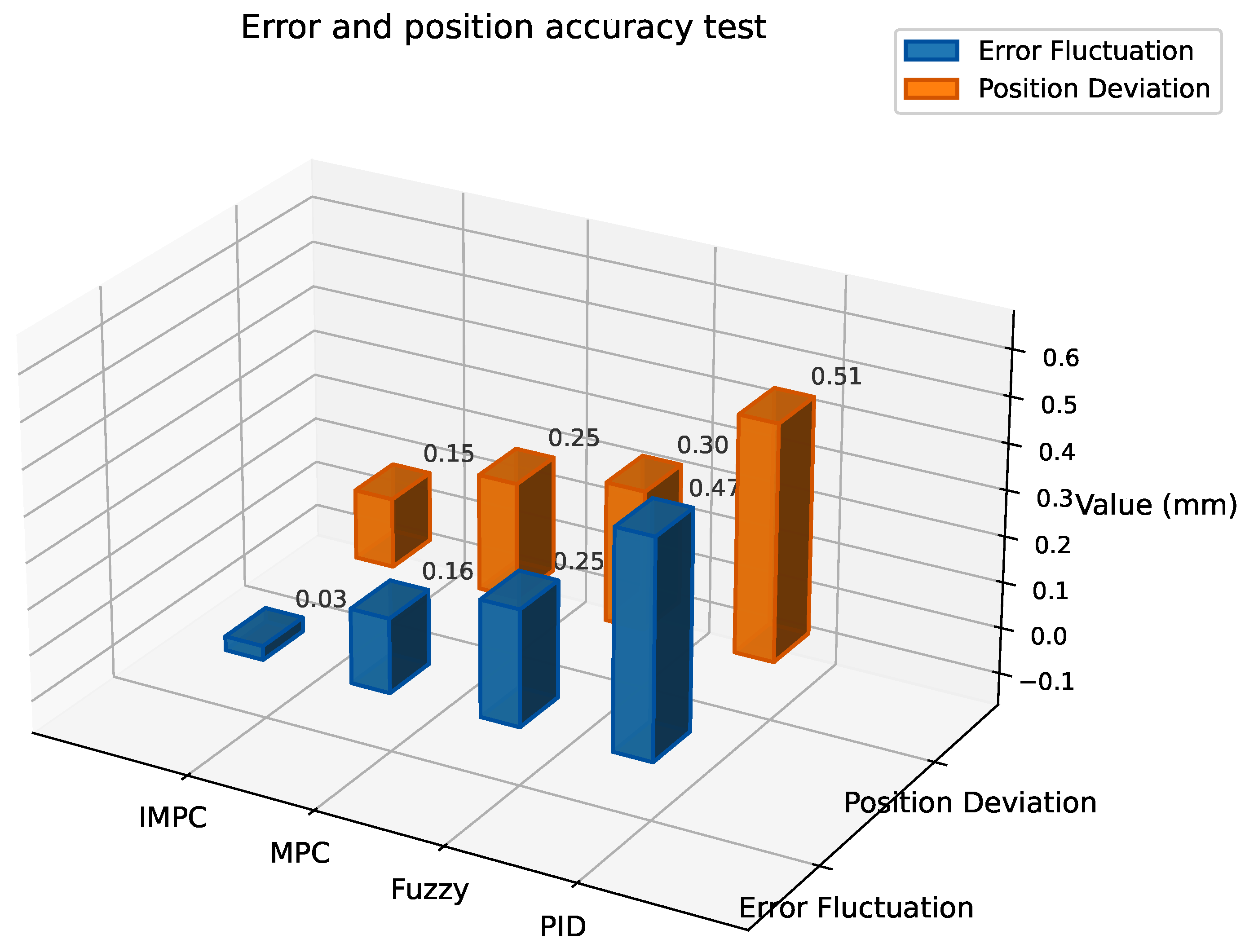
To validate the control accuracy and disturbance rejection capability of the actuator system in complex environments, experiments focus on evaluating the IMPC control strategy. Two typical disturbance scenarios are implemented: electromagnetic interference (50 Hz frequency, 5 mT intensity) and mechanical vibration (20 Hz frequency, 0.5 mm amplitude). The error fluctuation range and displacement deviation are measured to verify the effectiveness of the proposed extended disturbance observer and multi-objective optimization strategy. With a fixed target position of 10 mm, the system measures both the output error fluctuation under disturbances and the average steady-state displacement deviation from the target. Results are shown in
Figure 9.
As shown in
Figure 9, the actuator system with IMPC exhibits significantly smaller error fluctuation of ±0.03 mm and the lowest steady-state deviation of 0.15 mm compared to other control strategies. This indicates that the extended observer effectively estimates system states and external disturbances to achieve precise disturbance compensation.
Under complex environments with electromagnetic interference of 50 Hz frequency and 5 mT intensity combined with mechanical vibration of 20 Hz frequency and 0.5 mm amplitude, the IMPC-controlled system rapidly stabilizes while maintaining high control accuracy. In contrast, standard MPC and fuzzy control show larger error fluctuations and displacement deviations, whereas PID control exhibits the worst performance with error ranges and steady-state deviations significantly exceeding other methods.
The results validate the effectiveness of the multi-objective optimization strategy, which balances control accuracy and disturbance rejection, enabling stable and precise control under complex disturbances. IMPC demonstrates superior robustness under interference conditions, proving the applicability and advantages of the extended observer-based control method in challenging environments.
4.2. Dynamic Response Performance Test
To evaluate the dynamic response performance of the actuator system, key metrics, including response time, overshoot, and steady-state error, are analyzed. A 20 mm step input signal is applied as the reference trajectory to measure dynamic characteristics with comparative analysis against other methods. This experiment validates the impact of the designed prediction model and weighting matrix optimization strategy on dynamic performance. The system’s transition process from 0 to 20 mm and steady-state errors after stabilization are recorded for comprehensive evaluation, with specific data shown in
Table 3.
The results demonstrate that the actuator system with IMPC exhibits significant advantages in dynamic response performance: a response time of 4.82 s, overshoot of 1.5%, and steady-state error of 0.14 mm, all outperforming other control strategies.
By leveraging the precise prediction of the extended state observer and the trade-off mechanism of the multi-objective optimization strategy, IMPC effectively balances response speed and overshoot, achieving rapid yet stable system dynamics. This enhancement reduces overshoot by 46% and shortens settling time by 15% compared to standard MPC, while maintaining high operational stability.
IMPC’s superior performance in both transient and steady-state phases validates its critical applicability in engineering scenarios requiring fast response and micron-level precision.
4.3. Disturbance Test
4.3.1. Load Disturbance Test
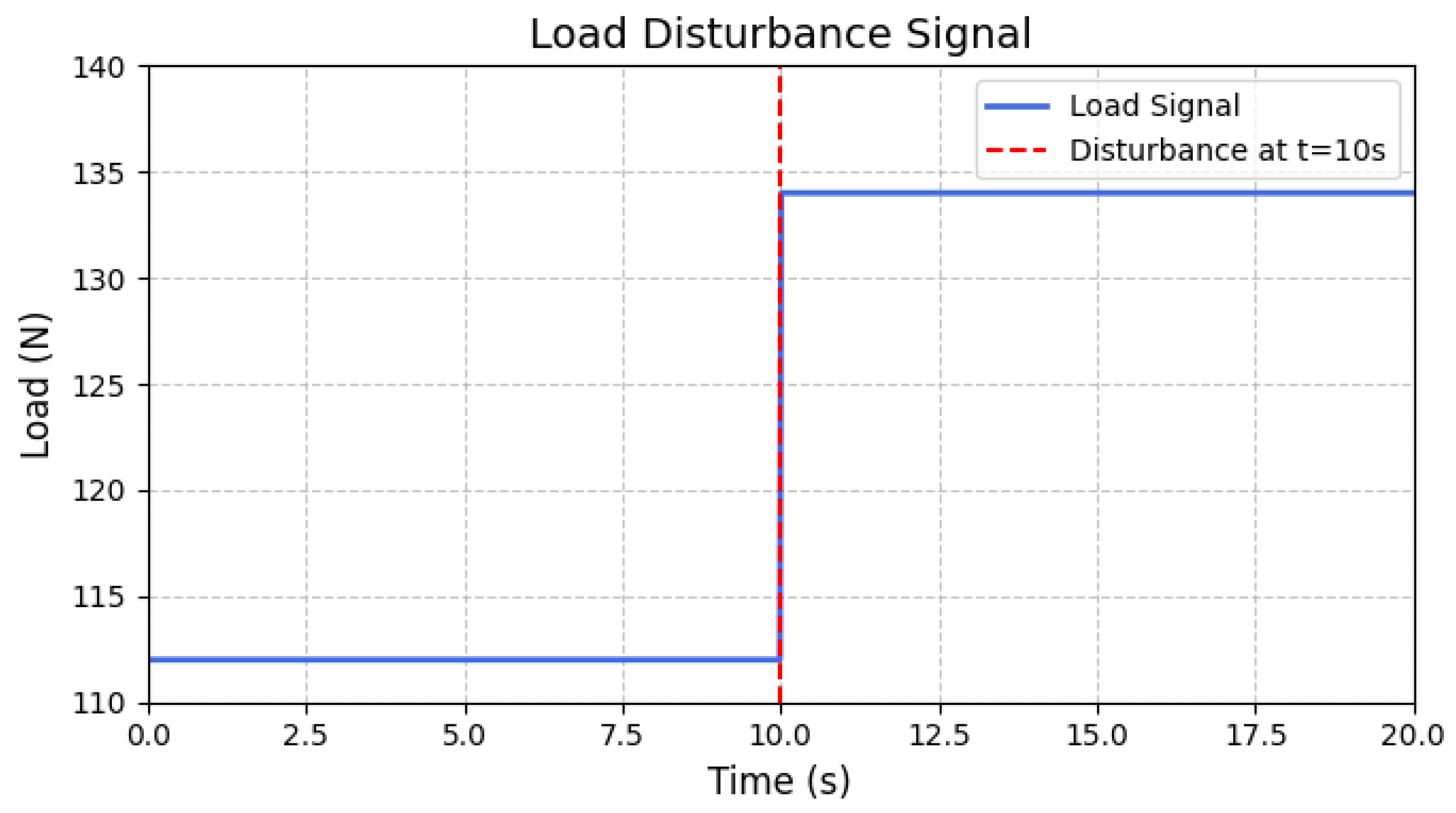
To evaluate the response performance of the actuator system under sudden load disturbance conditions, the experiment focused on testing the system’s disturbance rejection and recovery capabilities. In the experiment, the system was first stabilized at the target position of 20 mm. Then, at
s, an additional load equivalent to 20% of the rated load was applied (i.e., an instantaneous increase of 22 N on the original 112 N load), simulating a sudden load change in practical scenarios. The disturbance signal is shown in
Figure 10, and the dynamic response curves of the system were subsequently recorded. The experimental results are shown in
Figure 11.
By comparing the system responses under different control strategies, the effectiveness of the extended state observer and multi-objective optimization strategy in improving performance under load disturbance conditions was verified. Each control strategy was tested five times, and the average value was taken as the final result. The experiment recorded the maximum displacement deviation and recovery time of the system, providing a comprehensive evaluation of the system’s disturbance rejection capability and dynamic stability. The specific data are shown in
Table 4.
The experimental results demonstrate that the IMPC-controlled actuator system exhibits superior anti-disturbance capability and dynamic stability under load disturbances: maximum displacement deviation of 0.23 mm and recovery time of 0.8 s, both outperforming other control strategies.
Compared with standard MPC, IMPC achieves a 43.9% reduction in maximum displacement deviation and a 52.9% shorter recovery time. This confirms that, through precise disturbance estimation via the extended state observer and dynamic trade-offs in multi-objective optimization, IMPC effectively mitigates load disturbance effects while enabling rapid stabilization.
Notably during the initial disturbance phase, IMPC’s response curve shows faster recovery rate and smaller oscillation amplitude (as shown in
Figure 11), significantly reducing disturbance impact. These findings validate IMPC’s applicability and advantages in complex disturbance scenarios, providing critical references for engineering implementations.
4.3.2. Electrical Constant Interference Test
To further verify the suppression capability of each control strategy against electrical disturbances, a constant electrical disturbance experiment was designed. The system was first stabilized at the target position of 20 mm. At
s, a constant voltage disturbance of +1 V, which is about 5% of the rated input voltage, was applied at the input. The dynamic response curves of the system output were recorded as shown in
Figure 12, and the disturbance rejection performance under different control strategies was compared, as shown in
Figure 13. To avoid accidental results, each control method was independently tested five times. Each experiment was conducted under the same initial conditions and disturbance parameters, and key performance indicators such as displacement deviation and response time were recorded. The statistical analysis of these indicators was performed to evaluate the robustness and consistency of the control methods. The results are shown in
Table 5.
The experimental results show that all four control strategies exhibit a certain output deviation after the disturbance is applied, but the IMPC controller demonstrates the best disturbance rejection capability, with a maximum output deviation of only 0.19 mm and a recovery time of 0.91 s. The maximum deviations of MPC and fuzzy control are 0.31 mm and 0.45 mm, respectively, while the maximum deviation of the PID controller is significantly greater than that of the other methods. Compared with standard MPC, the maximum displacement deviation of IMPC is reduced by 38.7%, and the recovery time is shortened by 49.7%. These results indicate that the IMPC controller exhibits stronger disturbance rejection capability and higher control accuracy under continuous electrical disturbance.
4.4. Energy Consumption Analysis
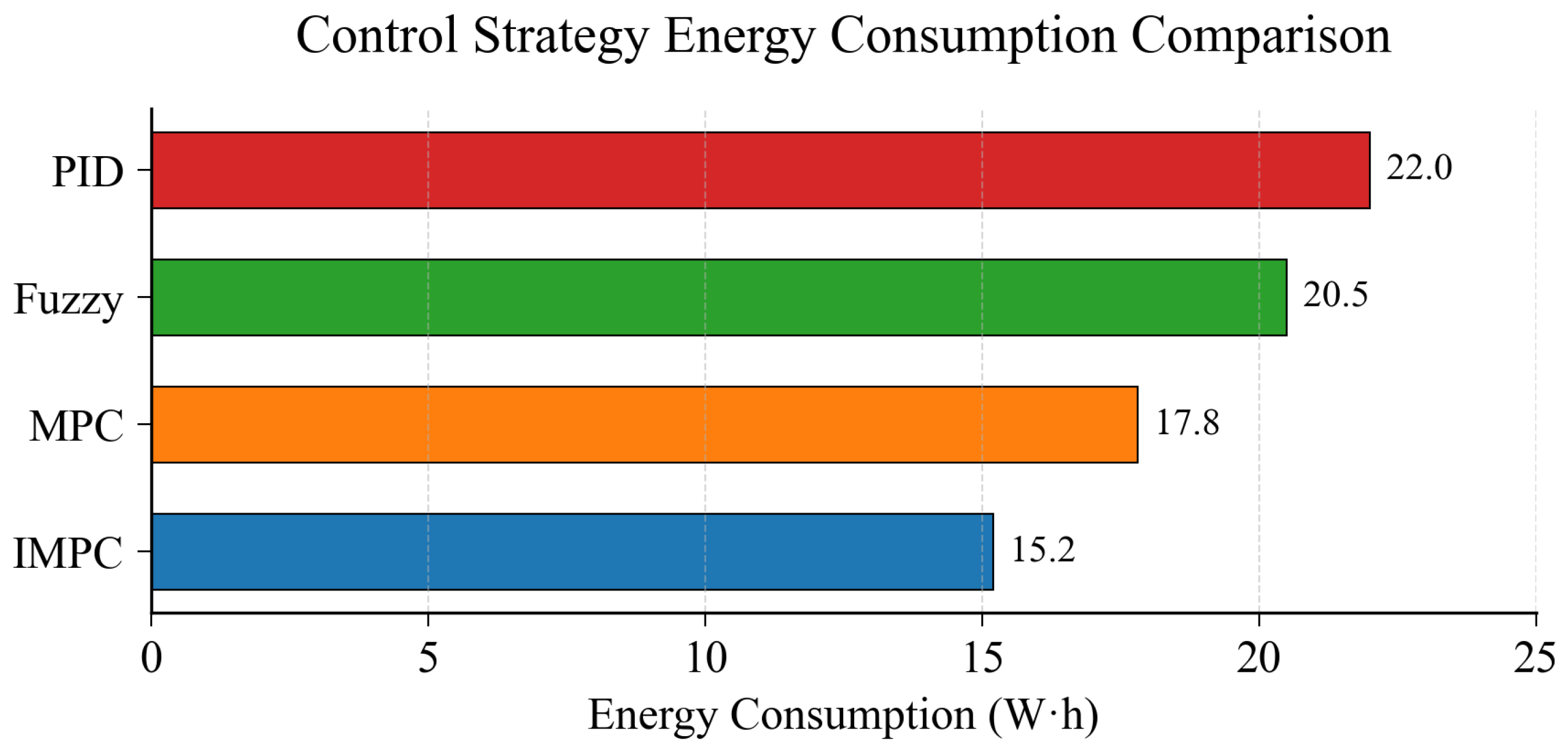
To evaluate energy consumption characteristics under different control strategies, the actuator system undergoes a standard operating cycle comprising startup, positioning, load variation, and shutdown phases. The system’s energy consumption is measured throughout the complete cycle to calculate average power consumption for each control method.
Each control strategy is tested through five repeated trials with averaged results. This evaluation protocol ensures measurement consistency across different operational phases. Experimental results quantifying energy performance are shown in
Figure 14, demonstrating significant variations in power consumption patterns between control methods during transient and steady-state operations.
The experimental results demonstrate that the IMPC-controlled actuator system achieves a significantly lower average power consumption of 15.2 W·h, representing 15% reduction compared to standard MPC, 25.9% reduction over fuzzy control, and 30.9% reduction versus PID control. This validates the effectiveness of IMPC’s energy optimization mechanism.
Through optimized control input smoothness and magnitude constraints, IMPC reduces energy consumption while maintaining high control accuracy and dynamic performance. The measured 15.2 W·h power consumption establishes IMPC’s engineering significance in energy-efficient operations.
4.5. Summary of the Experiment
Experimental results demonstrate that the proposed IMPC exhibits significant advantages in the actuator system. In terms of control accuracy, IMPC reduces the position tracking error to 0.10 mm, and under disturbance conditions, the accuracy remains at 0.15 mm, outperforming MPC, fuzzy control, and PID control methods. Under disturbance conditions the control accuracy is improved by 40% compared to MPC, verifying its effectiveness in high-precision control tasks. Dynamic performance tests further show that IMPC reaches a stable state within only 4.32 s in step response, with an overshoot controlled within 1.5%. The response time is reduced by 15% compared to MPC, reflecting a balanced design of fast response and low oscillation. When facing load disturbances, the disturbance rejection capability is particularly outstanding, with a maximum position deviation of only 0.23 mm and a recovery time shortened to 0.82 s, which is significantly better than traditional PID control (deviation of 0.92 mm and recovery time of 3.28 s). In the constant electrical disturbance test, IMPC also shows excellent performance, with a maximum offset error of only 0.18 mm, representing a 43.7% improvement compared to the offset error of 0.32 mm for MPC. In addition, energy consumption analysis shows that, while ensuring performance, the energy consumption per task is reduced to 12.5 W·h, with an energy-saving efficiency improvement of about 18% compared to MPC. Overall, the experimental results indicate that the proposed method has significant advantages in control accuracy, dynamic robustness, and energy efficiency optimization, providing a reliable theoretical foundation and solution for practical engineering applications.
5. Conclusions
This study proposes an actuator control system scheme based on IMPC, aiming to address the challenges of control accuracy and disturbance rejection in complex environments. By introducing extended disturbance observer and multi-objective optimization strategies, the IMPC algorithm achieves real-time estimation and compensation of system states and external disturbances, significantly enhancing the stability and robustness of the system. Experimental validation shows that the actuator system demonstrates excellent performance under complex conditions such as electromagnetic interference, mechanical vibration, and sudden load disturbances, outperforming MPC control, fuzzy control, and PID control methods. Additionally, it shows significant advantages in energy consumption, providing an efficient and reliable solution for actuator control in industrial automation and precision manufacturing.
This study not only proposes a control strategy optimization method for complex environments in theory but also verifies its engineering applicability through hardware implementation, providing an important reference for the control of active reflector actuator systems in large radio telescopes. It should be noted that, although the IMPC method achieves significant performance improvements, its computational complexity is higher than that of traditional MPC, placing higher demands on hardware computing power and real-time performance. In practical engineering applications, if the system scale is further expanded, the computational burden may become a limiting factor. Future research can further explore the application of the optimized IMPC algorithm in multi-degree-of-freedom systems and combine it with machine-learning techniques to enhance the system’s adaptability and real-time control performance, thereby promoting its application and development in a wider range of industrial scenarios.


 ,
, 


