Article

A Study on a Variable-Gain PID Control for a Pneumatic Servo System Using an Optimized PSO-Type Neural Network

Graduate School of Science and Engineering, Ehime University, Matsuyama 790-8577, Japan
*
Author to whom correspondence should be addressed.
Actuators 2025, 14(5), 250; https://doi.org/10.3390/act14050250
Submission received: 23 October 2024 / Revised: 1 May 2025 / Accepted: 13 May 2025 / Published: 16 May 2025
(This article belongs to the Special Issue Intelligent Control for Pneumatic Servo System)

Abstract

:
This study investigates the application of proportional–integral–derivative (PID) control enhanced with an optimized particle swarm optimization (OPSO)-type neural network (NN) to improve the control performance of a pneumatic servo system. Traditional PID methods struggle with inherent nonlinearities in pneumatic servo systems. To address this limitation, we integrate two OPSO-type NNs within the PID framework, thereby developing a robust control strategy that compensates for these nonlinear characteristics. The OPSO-type NNs are particularly efficient in solving complex optimization problems without requiring differential information, demonstrating superior simplicity and efficacy compared to traditional methods, such as genetic algorithms. In our approach, one of the OPSO-type NNs is utilized to tune the PID controller gains, while the other adjusts the control output. The experimental results show that the proposed method enhances the position control accuracy of the pneumatic servo system. Furthermore, this approach holds promise for improving the responsiveness, stability, and disturbance suppression capabilities of pneumatic systems, paving the way for advanced control applications in this field.

1. Introduction

Pneumatic servo systems, which utilize air as a power source, provide economical and safe alternatives to hydraulic equipment. These systems are characterized by their emission-free operation and minimal maintenance requirements, making them particularly advantageous across various applications. Their compact design allows for substantial output capabilities, leading to widespread adoption as actuators in industrial robotics. Additionally, the inherent compressibility of air offers significant benefits, such as effective shock absorption and the mitigation of reaction forces, positioning these systems as promising solutions for rehabilitation devices and other equipment involving human interaction [1,2].
Despite these advantages, pneumatic servo systems exhibit nonlinear characteristics arising from delays in air-pressure response, friction between pistons and cylinders, and pressure variations due to temperature changes. These nonlinearities present challenges in achieving precise control and stability.
To address these issues, many control methods have been proposed. L. Zhao, et al. presented an active disturbance rejection position control scheme for a magnetic, rodless cylinder in servo systems without pressure states. The method effectively reduced the overshot using a tracking differentiator. Meanwhile, nonlinearity is estimated using a designed extended-state observer [3]. W. Deng, et al. proposed a recursive robust integral of the sign of the error (RISE) control method for mechanical servo systems with mismatched uncertainties. In controller development, two auxiliary error signals are introduced into the recursive backstepping design framework, and then RISE feedbacks are synthesized to eliminate the matched and mismatched uncertainties simultaneously [4]. Active disturbance rejection control (ADRC) is a possibility-based online estimating disturbance rejection control method. It is attractive for use in various applications. S. Gu et al. proposed a variable-gain active disturbance rejection control (VGADRC) method to solve the trajectory-tracking problem of delta parallel manipulators with disturbances [5]. The method employs a variable gain-tracking differentiator (VGTD), a variable-gain extended-state observer (VGESO), and a variable-gain controller (VGC), and it incorporates error-based variable gains to improve control performance. A novel event-triggered finite-time variable gain ADRC strategy is proposed for master-slave teleoperated parallel manipulators by Gu et al. [6]. It integrates error-based variable gains and event-triggered mechanisms to enhance control performance and reduce communication burden, with stability analysis, steady-state performance evaluation, and avoidance of the Zeno phenomenon validated through simulations and experiments. Zhang et al. proposed a novel tuning method for ADRC to extend its application to high-order electro-hydraulic servo systems by decomposing ADRC into a pre-filter H ( s ) and a controller T ( s ) in the frequency domain, with parameter tuning based on quantitative feedback theory, demonstrating superior performance compared to traditional bandwidth tuning methods through simulations and experimental validation [7]. G. Herbst et al. employed a tuning implementation in a discrete-time domain for three different error-based ADRC applications [8]. In the paper, it is shown that these are almost one-to-one counterparts of existing output-based implementations, to the point where transfer functions and coefficients can be reused in unaltered form. A finite-time trajectory-tracking control strategy for a rodless pneumatic cylinder system with disturbances was developed using an inner-outer loop framework by L. Zhao, et al. [9] In the framework, a generalized, nonlinear, extended state observer and an inner loop controller compensate for matched disturbances, while a super-twisting extended state observer and an outer loop controller address unmatched disturbances, ensuring finite-time stability, which was validated with experimental results. Similarly, H. Sun et al. proposed a novel position-tracking control strategy for high-pressure pneumatic servo systems integrating extended state observers (ESOs) and sliding mode control (SMC) within a command-filtered backstepping framework to compensate for matched and mismatched disturbances, enhance robustness, and mitigate high switching gains, with system stability ensured via Lyapunov theory and validated through numerical simulations, demonstrating an improved response speed and tracking accuracy [10].
Furthermore, with the rapid advancement of artificial intelligence, many methods with intelligent algorithms have also been developed in recent years. Their applications attract more and more attention [11,12,13]. J. Li et al. proposed an intelligent control method using IMC control combined with NN [11]. The IMC ensured the great minimization of disturbance, offering stability and robustness properties in the method. NN was applied to achieve a suitable control parameter to deal with the non-linear elements of the plant. A hybrid electric–pneumatic actuator was analyzed theoretically and tested experimentally by F. Jiang et al. [12]. A BP neural network model for pneumatic system inflation and deflation was developed by selecting appropriate state parameters, and a prediction algorithm was proposed to predict the output force of the system for a period of time during the process of inflation (deflation). The prediction of output force variation provides an effective method for the dynamic modeling of complex pneumatic systems. Y. Chen et al. proposed an adaptive, robust neural network controller (ARNNC) synthesized for a single-rod pneumatic actuator to achieve high tracking accuracy without the bounds of the parameters and disturbances being known [13]. The ARNNC control framework integrates adaptive control, robust control, and neural network control intelligently. The effectiveness of the proposed ARNNC was confirmed by a high tracking accuracy.
According to our previous research, the integration of proportional–integral–derivative (PID) control with neural networks (NNs) has proven effective in the intelligent control of plants with nonlinear elements [14]. NNs, which mathematically model the functionalities of the human brain, excel in processing and separating nonlinear data. Traditional NN approaches often rely on back propagation (BP) to update connection weights. However, this method requires differential information, complicating the computation process. In contrast, particle swarm optimization (PSO) utilizes only the numerical values of evaluation functions for optimization. This approach enables the resolution of complex nonlinear optimization problems without the need for continuity or differential information. PSO is an optimization method developed by J. Kennedy and R. Eberhart in 1995 [15,16]. It is a multiple-dimensional optimization method based on the collective search behavior of flocks of birds and schools of fish. The algorithm involves numerous particles moving through a dimensional space to search for solutions that optimize the objective function. Notable features of PSO include its ability to search for solutions rapidly compared to traditional heuristic methods, its applicability to continuous problems without requiring derivative information of the objective function, and the presence of several parameters that significantly influence its search capabilities [12,17]. By employing PSO algorithms, methods of training NNs in various scenarios have been confirmed. C. Lin et al. designed an evolutionary neural fuzzy network using the functional-link-based neural fuzzy network (FLNFN) and a new evolutionary learning algorithm [18]. The evolutionary learning algorithm is based on a hybrid of cooperative PSO and a cultural algorithm. The proposed FLNFN model uses functional-link neural networks as the consequent part of the fuzzy rules. Finally, the proposed functional link-based neural fuzzy network with cultural cooperative PSO (FLNFN-CCPSO) is adopted in several predictive applications. J. Chen et al. proposed a satisfactory and efficient algorithm for training an artificial NN in supervised learning using the method of PSO combined with the Cuckoo Search (CS) algorithm [19]. The proposed hybrid algorithm is employed as a new training method for feedforward neural networks (FNNs). To investigate the performance of the proposed algorithm, two benchmark problems are used, and the results are compared with those obtained from FNNs trained with original PSO and CS algorithms. The experimental results show that the proposed hybrid algorithm outperforms both PSO and CS in training FNNs. S. Mirjalili et al. proposed a hybrid of PSO and the gravitational search algorithm (GSA) to achieve a faster searching speed [20]. In their work, GSA and PSOGSA are employed as new training methods for feedforward neural networks (FNNs) in order to investigate the efficiencies of these algorithms in reducing the problems of trapping in local minima and the slow convergence rate of current evolutionary learning algorithms. The experimental results of the proposed method show that PSOGSA outperforms both PSO and GSA for training FNNs in terms of converging speed and avoiding local minima. It has also been proven that an FNN trained with PSOGSA achieves better accuracy than one trained with GSA.
Recent advancements have focused on optimized particle swarm optimization (OPSO), which introduces a meta-optimization layer to PSO, where a higher-level “super-swarm” optimizes the parameters of subordinate swarms. This hierarchical structure allows the subordinate swarms to handle the optimization task while the super-swarm adjusts their parameters, improving overall performance. This concept has been effectively applied to the training of neural networks, leading to substantial reductions in training time and improvements in prediction accuracy [21]. In this study, we propose a variable-gain PID control strategy employing an optimized particle swarm optimization (OPSO)-type NN to update connection weights, referred to as OPSO-NN. Compared to traditional PSO, OPSO demonstrates faster convergence and requires fewer tuning parameters. This research specifically aims to enhance the accuracy and responsiveness of position control in pneumatic servo systems using OPSO-NN-based PID tuning.
The structure of this paper is organized as follows: Section 2 outlines the pneumatic servo systems utilized in this study. Section 3 provides an overview of fixed-gain PID control, the architecture of NNs, the principles of PSO, and variable-gain PID control using OPSO-type NNs. Section 4 details the experimental procedures conducted to assess the proposed method’s effectiveness and discusses the resulting data. The Section 5 concludes the paper by synthesizing the key findings and implications of the research.

2. Pneumatic Servo System

The system configuration of the horizontal pneumatic servo system used in this study is shown in Figure 1. The parameters of pneumatic servo system are shown in Table 1.
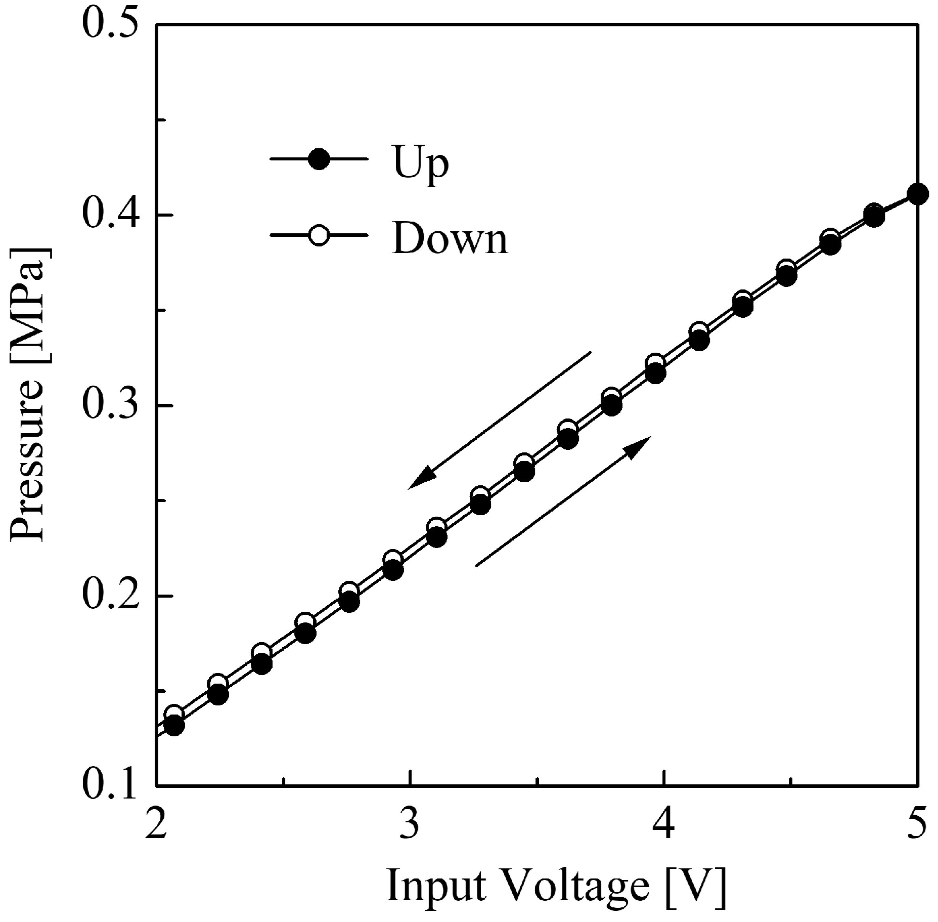
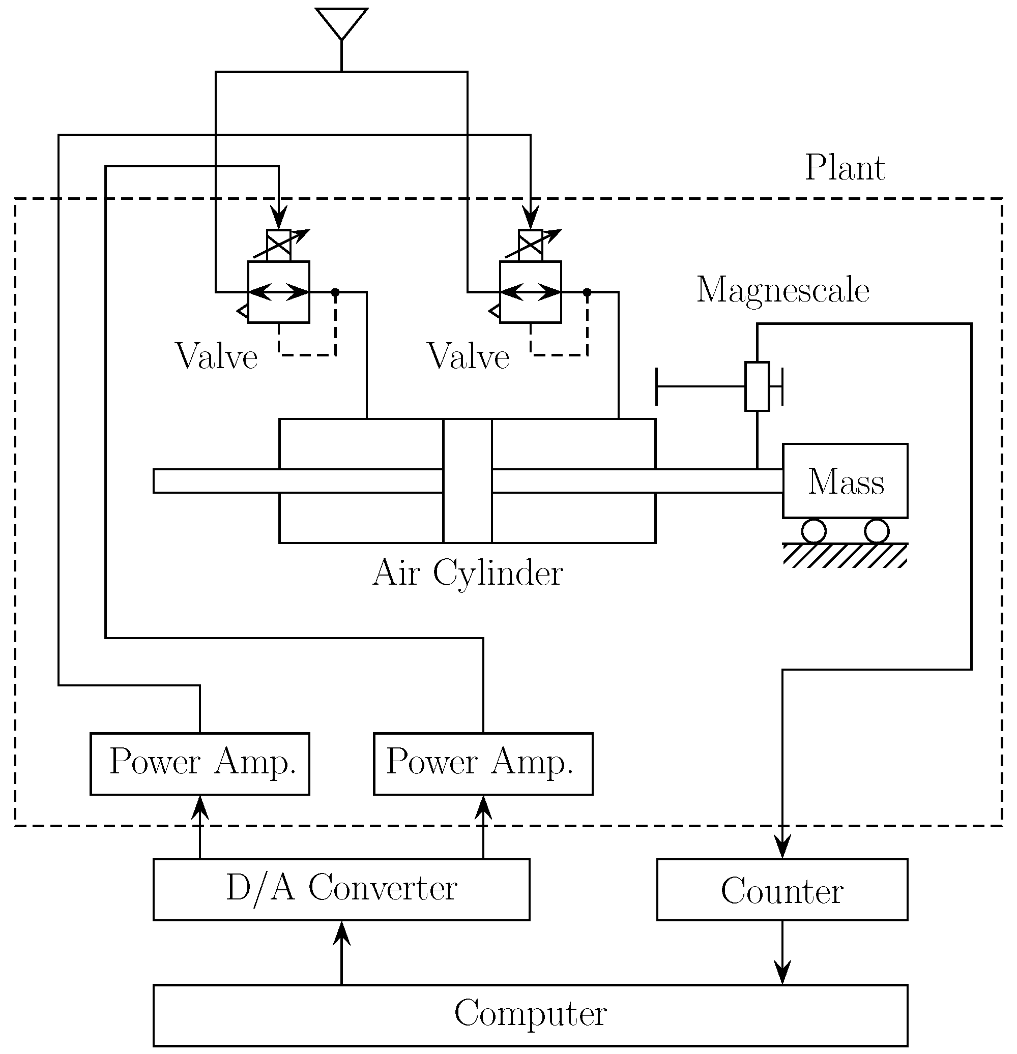
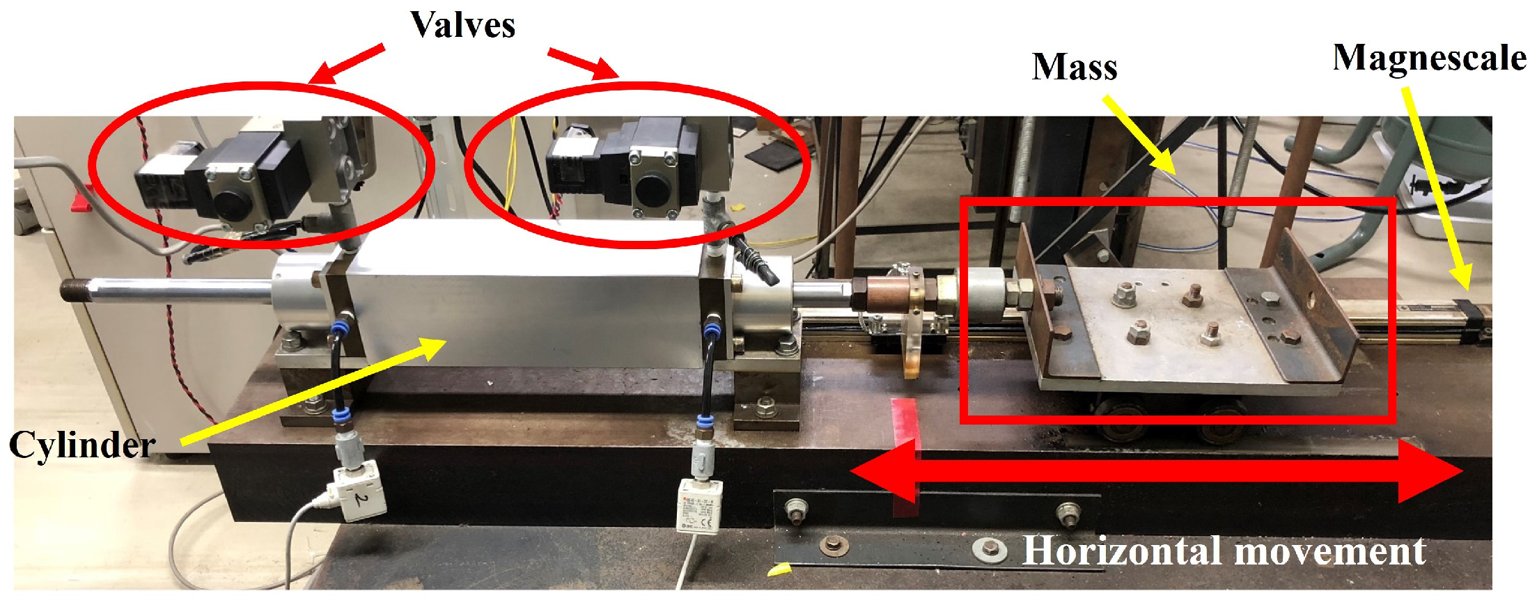
The primary actuator is the cylinder installed horizontally in the servo system. The pneumatic cylinder converts compressed air into linear motion. It is essential for generating the necessary force to move the attached mass, allowing for precise control over its position horizontally. The appearance of the experimental apparatus is illustrated in Figure 2. Two three-way electro-pneumatic proportional pressure control valves are applied in the system. These valves regulate the airflow to the cylinder, enabling the pressure and direction of the pneumatic force applied to the mass. Offering an effective control signal to valves is crucial for achieving the desired response characteristics of the system. To obtain precision position control of the pneumatic servo system, the supply pressure for controlling the valves is expressed as P 1 and P 2 . The specific pressure characteristics are shown in Figure 3. A magnescale is employed in this servo system for the accurate position detection of the moving mass. The data obtained from the magnescale are sent via the counter board to the computer, ensuring that the servo system can maintain precise positioning. The computer processes the input data from the counter and magnescale, executes the control algorithms, and sends control commands to the D/A converter for real-time actuation. The power amplifiers boost the control signals sent from the computer through the D/A converter, ensuring that adequate power is supplied to the actuator for control operation.
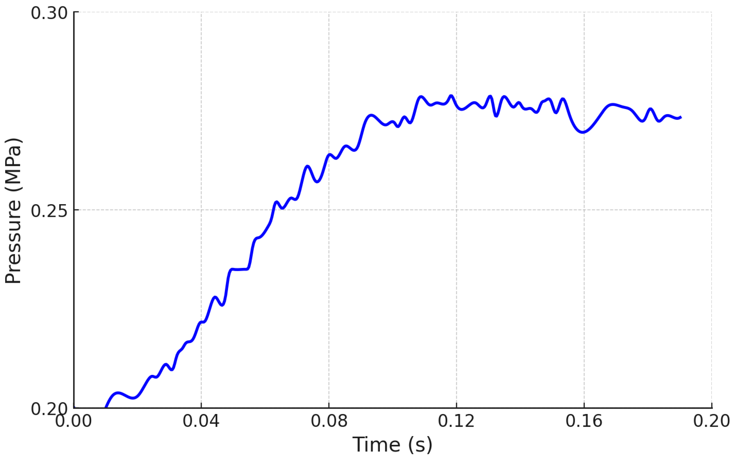
Figure 3 illustrates the input–output characteristics of the control valve, including the amplifier. The position detection of the cylinder is conducted using a magnescale sensor (Sony Magnescale SR50-50A: effective length 500 mm). The signal from the magnescale is converted into a pulse signal corresponding to the displacement by a detector circuit (Sony Magnescale MD30-1G5C). Subsequently, the signal is counted via a counter board (Interface Inc. 6201E) and input into a computer as a digital signal. The resolution of position detection on the computer is 5 µm. The control signal for the control valve is output from the computer to a D/A converter (Interface Inc. 3346A) as a digital signal. The D/A converter uses two channels; if one channel’s output is positive, the other’s is negative, thus outputting opposite control signals. These control signals are converted to analog through the D/A converter and drive the pneumatic cylinder via the power amplifier and control valve. Since the pneumatic servo system includes nonlinear elements, it is practically impossible to make a complete control model. Therefore, we consider the plant with the input–output characteristics shown in Figure 3 as the target for control. In this case, a dead time of 0.04 s is included in the control input to account for operational delays and computation time. Figure 4 illustrates the pressure response within the cylinder when a step input voltage is applied to the power amplifier of an electro-pneumatic proportional pressure-control valve. This measurement was obtained by fixing one end of the cylinder and changing the input voltage from 5 V to 6 V (corresponding to a change in the secondary pressure from P A = 0.2 MPa to P A = 0.28 MPa). From the figure, it is evident that the relationship between the applied voltage and the cylinder pressure can be approximated by a first-order lag system with dead time. Here, a dead time of 40 ms was incorporated into the control input, taking into account the computational time of 30 ms for the operational delay [22].

3. Proposed Method

3.1. PID Control

The history of PID (proportional integral differential) control is long, making it one of the most established methods for control system design. It is still widely used today and is expected to be widely employed in the future. The practical appeal of PID control lies in its versatility. Unlike modern control theory, it does not require a mathematical model of the plant, and it is said to achieve sufficient practical effects in many situations, especially in the field of process control. It is composed of simple proportional, integral, and differential actions, making the roles of each control action intuitively easy to understand.
Figure 5 shows the basic form of PID control. The difference between the objective value r ( t ) and the controlled variable y ( t ) , representing the difference between the desired value and the actual value of y ( t ) , is called error, e ( t ) . Based on this error, the control input u ( t ) is determined. It is appropriate that the control input is small when the error is small and large when the error is large, so a term proportional to the error is included in the control law, which is called proportional action. When only proportional control is applied to a self-balancing control object, a constant error remains in response to step changes in the target value or disturbances. This is called a steady-state error or offset, which can be eliminated by including a term proportional to the integral of the error in the control law, called integral action. To reflect the trend of an increase or a decrease in the error in determining the control input and improve control characteristics, a term proportional to the derivative of the error is also included in the control law, called derivative action. The control law that includes these three actions is PID control. The control input u ( t ) can be given through the following equation
u ( t ) = K P { ( e ( t ) + 1 T I e ( t ) d t + T D d e ( t ) d t
e ( t ) = r ( t ) y ( t )
where K P is the proportional gain, T I is the integral time, and T D is the derivative time. Next, in a discrete-time system, the discretization of Equation (1) can be expressed as
u ( k ) = K P e ( k ) + T T I Σ j = 0 k e ( j ) + T D T { e ( k ) e ( k 1 ) }
Additionally, according to Equation (3), u ( k 1 ) can be obtained as the following equation:
u ( k 1 ) = K P { ( e ( k 1 ) + T T I Σ j = 0 k 1 e ( j ) d t + T D T { e ( k 1 ) e ( k 2 ) } }
To simplify discrete PID implementation, Equation (5) expresses the control output in an incremental form as follows:
u p i d ( k ) = u ( k 1 ) + K P { ( e ( k ) e ( k 1 ) } + K I e ( k ) + K D { e ( k ) 2 e ( k 1 ) + e ( k 2 ) }
where we set the integral gain K I as K I = K P T T I and the derivative gain K D as K D = K P T D T .

3.2. Proposed Intelligent PID Control Using OPSO-Type NN

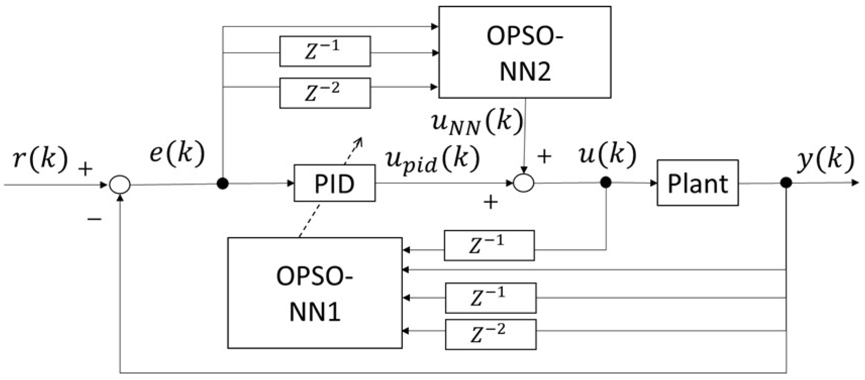
Building on the discrete PID control described earlier, we propose an intelligent PID control method integrated with OPSO-based neural networks. In our proposed method, the OPSO-NN-type PID control system updates the connection weights of the NN using OPSO and tunes the PID gains using the NN for variable-gain PID control. Figure 6 shows the structure of the OPSO-NN-type PID control system. OPSO-NN1 is an NN for PID gain adjustment, and OPSO-NN2 is an NN for control input adjustment. OPSO-NN1 receives the control input from the previous time step and the control output up to two previous time steps to calculate the change in PID gains. Additionally, OPSO-NN2 receives the errors up to two previous time steps to adjust the control input. Through these procedures, we attempted the position control of the pneumatic servo system.
The architecture was designed to achieve precise control of the system output by adjusting the control signals based on the feedback received from the pneumatic servo system. The OPSO-NN1 utilizes the past inputs and outputs from the system. By learning from historical data, this network can adaptively tune its parameters to better respond to the system’s dynamics. The OPSO-NN2 processes the outputs, providing further refinement to the control signal. The output from OPSO-NN2 is combined with u ( k ) , which accounts for both traditional PID control and adaptive NN responses. u ( k ) is the sum of the PID controller’s output and the NN’s output. The integrated approach allows for improved system performance, as the PID controller provides stability, while the NNs offer adaptability to changing system dynamics. The figure showcases the proposed sophisticated control system that combines the robustness of a PID control with the adaptability of NNs. This innovative architecture is particularly relevant for applications requiring precise control in environments characterized by uncertainty and variability, exemplifying the convergence of traditional control theories and modern intelligent methodologies in engineering practices.

3.2.1. NN Structure in the Proposed Method

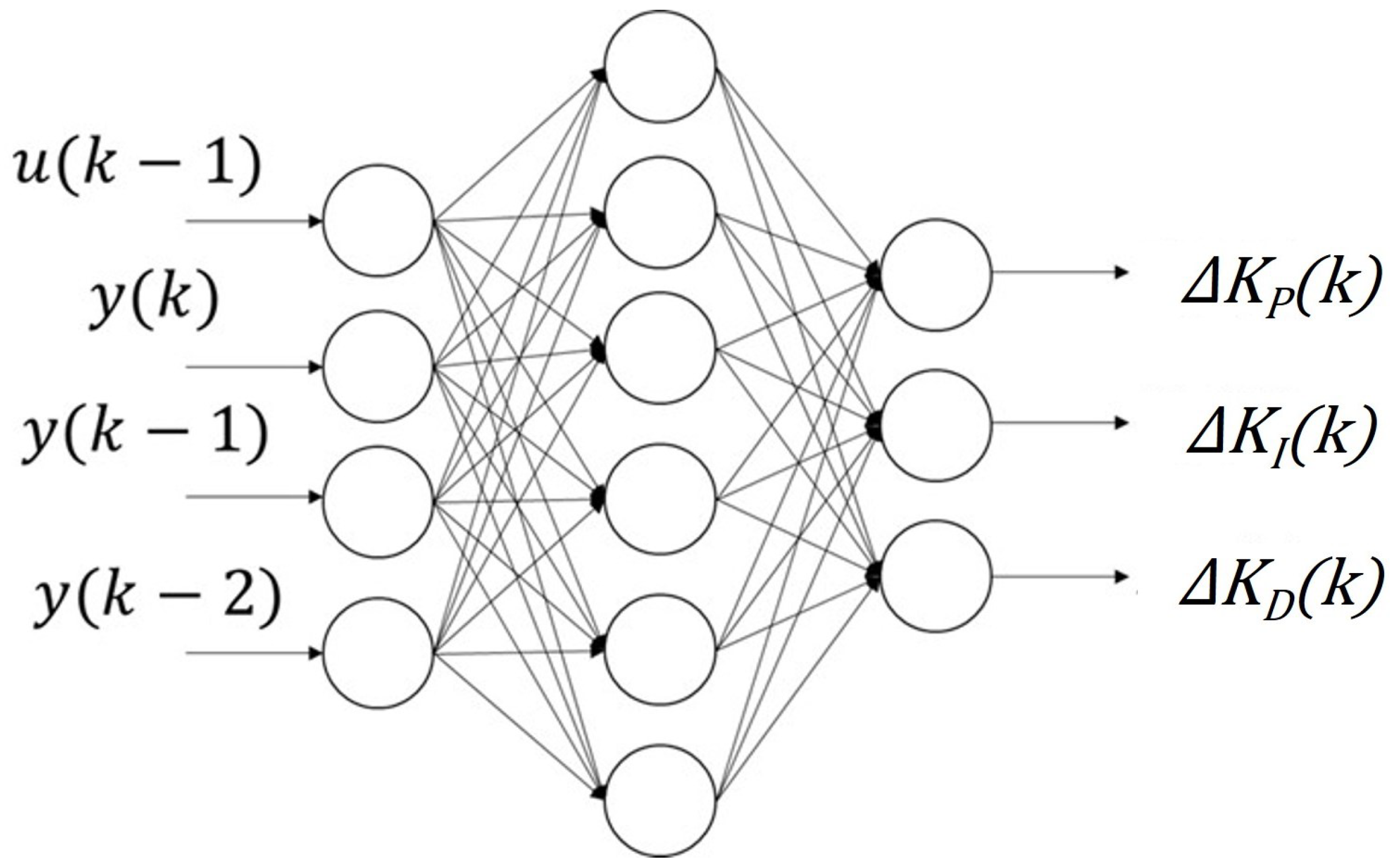
Figure 7 illustrates the architecture of the NN in OPSO-NN1 designed to tune the gains of PID controller. This structure is designed to enhance the performance when dealing with the nonlinear element of the pneumatic servo system. The input layer consists of key nodes representing the control input to the pneumatic servo system at one previous step, u ( k 1 ) and the control output of the plant at the current step, y ( k ) , at one previous step, y ( k 1 ) , and at two previous steps, y ( k 2 ) . There is a hidden layer that processes the inputs through interconnected nodes. This layer is responsible for learning the relationships and dynamics of the system, allowing the network to model the underlying complexities. The output layer comprises three nodes that correspond to the adjustments in the PID controller’s gains: Δ K P ( k ) , Δ K I ( k ) , and Δ K D ( k ) . The gains of PID control can be expressed as
K P ( k ) = K P × ( 1 + Δ K P )
K I ( k ) = K I × ( 1 + Δ K I )
K D ( k ) = K D × ( 1 + Δ K D )
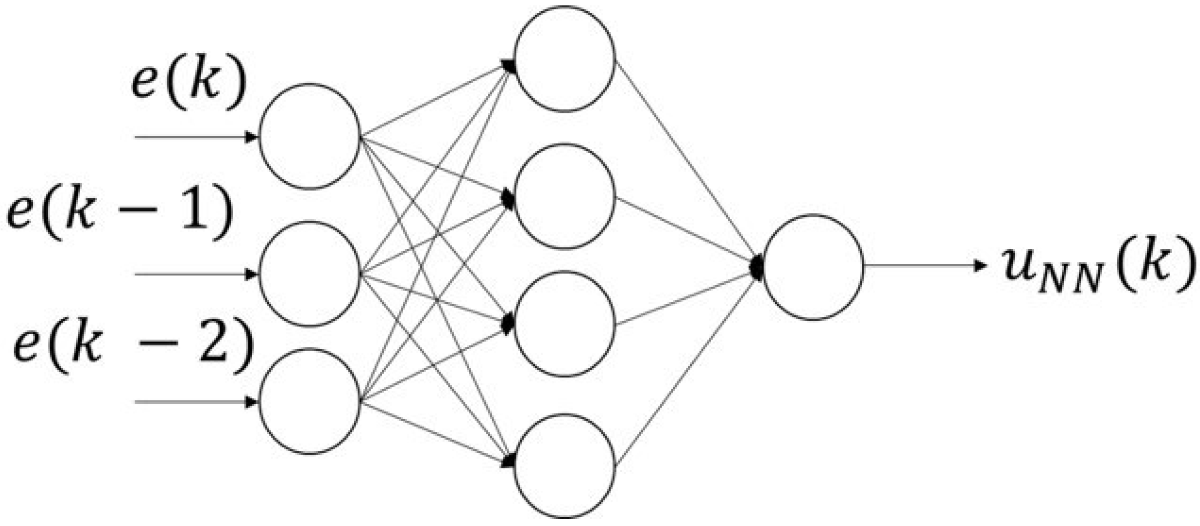
Figure 8 illustrates the architecture of the NN in OPSO-NN2 designed to estimate the compensation output of u N N based on the error of the servo system. This structure is integral to enhancing the control performance. The input layer consists of three nodes representing the current and past error signals, e ( k ) , e ( k 1 ) , and e ( k 2 ) . The hidden layer contains multiple interconnected nodes that process the input error signals. This layer is essential for learning the relationships between the error signals and the necessary control adjustments. The output layer features a single node that computes the control signal, u N N ( k ) . Then, the control signal to the plant can be estimated as
u ( k ) = u p i d ( k ) + u N N ( k )
The activation function used in both of OPSO-NN1 and OPSO-NN2 is
f ( x ) = 1 1 + e x 0.5

3.2.2. PSO in the Proposed Method

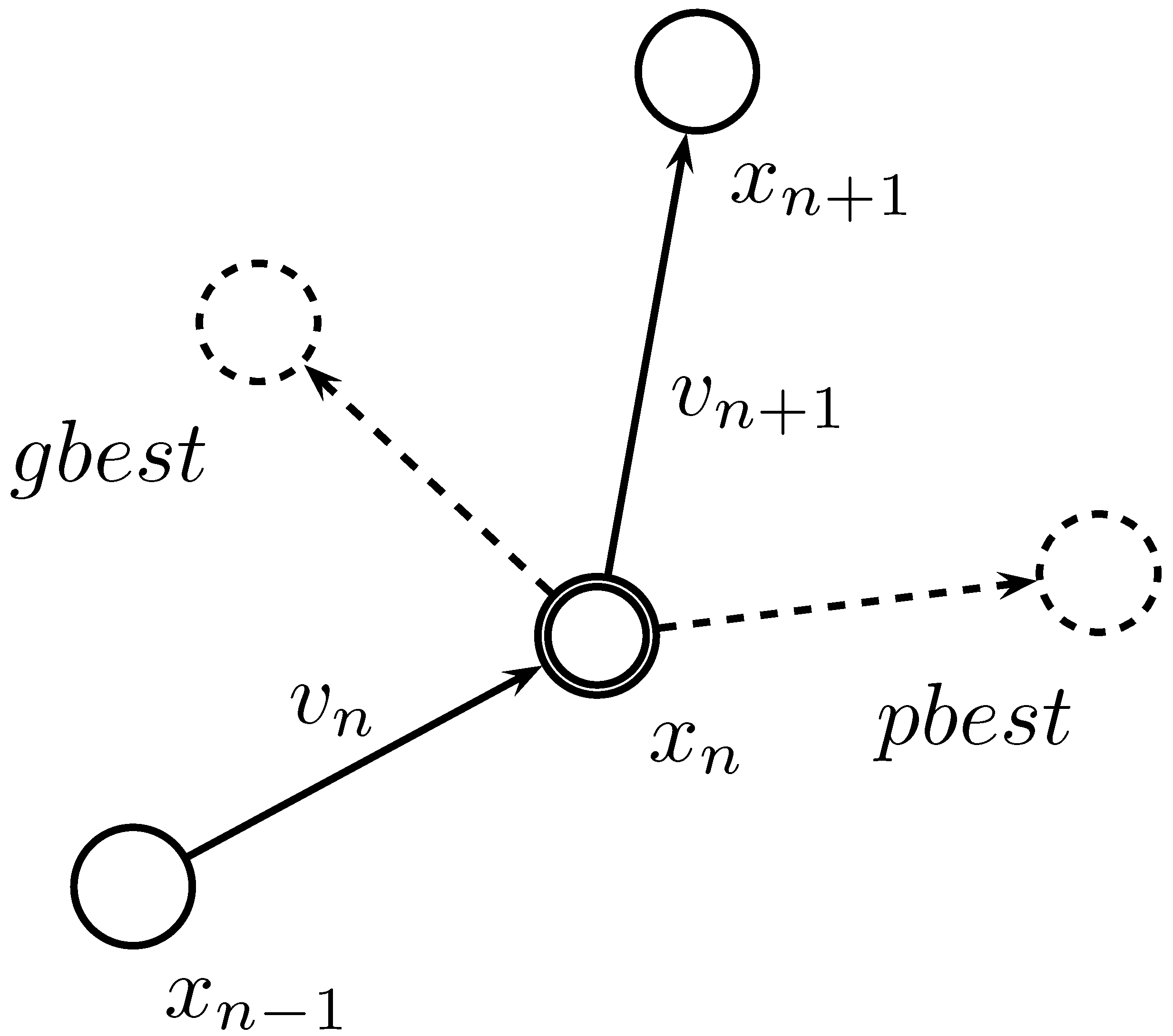
In the PSO algorithm that is applied in our proposed method, each individual in the swarm possesses information about its current position and velocity. Using this information, the position of each individual is updated in subsequent iterations. The updates for position and velocity are calculated using Equations (11) and (12).
v n + 1 = ω v n + C 1 r 1 ( p b e s t n x n ) + C 2 r 2 ( g b e s t n x n )
x n + 1 = x n + v n + 1
In the math expression of PSO, n represents the number of iterations, x is the particle position, p b e s t is the individual best position, g b e s t is the global best position, v is the particle velocity, ω is the inertia weight, C 1 and C 2 are acceleration coefficients, and r 1 and r 2 are uniformly distributed random numbers between 0 and 1. The conceptual diagram of the update method for search points in PSO can be depicted as Figure 9 shows. The figure shows the movement of a particle, which is crucial as it explores the solution space. It can be seen that the position update of a particle from x n to x n + 1 is influenced by its current velocity and the new velocity. Each particle maintains a record of the best solution it has found so far ( p b e s t ), while the swarm collectively keeps track of the best solution found via any particle in the group ( g b e s t ). These values are integral to guiding the particles towards optimal solutions. The update of particle velocities is governed via cognitive and social components, allowing each particle to adjust its trajectory based on both personal experiences and the knowledge of other particles. This dual influence is key to the efficiency of the PSO algorithm.

3.2.3. OPSO in the Proposed Method

OPSO is an advanced optimization technique developed by G. Schneider et al. in 2006 [1]. In PSO algorithms, finding the optimal combination of PSO parameters is, in itself, an optimization problem. The performance of the PSO algorithm is highly dependent on the proper tuning of these parameters, which directly impacts its ability to efficiently explore the solution space and converge towards optimal solutions. In our previous work, to identify the best combination of PSO parameters, trial and error tests involving numerous combinations were implemented. However, the empirical approach can be labor-intensive and may not yield optimal results across diverse problem landscapes. Then, the OPSO method addresses these limitations by integrating optimization strategies specifically designed to enhance the performance of PSO. The updating of a particle in OPSO can be expressed as
v n + 1 = ω v n + C 1 r 1 ( p b e s t n x n ) + C 2 r 2 ( g b e s t n x n )
x n + 1 = x n + v n + 1
s n + 1 = g s n + C 1 r 1 ( p b e s t n y n ) + C 2 r 2 ( g b e s t n y n )
y n + 1 = y n + s n + 1
In OPSO, n represents the number of iterations, x and y are the particle positions, p b e s t and p b e s t are the individual best positions, g b e s t and g b e s t are the global best positions, v and s are the particle velocities, ω and g are the inertia weights, C 1 , C 2 and C 1 , C 2 are acceleration coefficients, and r 1 , r 2 , and r 1 and r 2 are uniformly distributed random numbers between 0 and 1.
In this study, we introduce the PSO described by Equations (13) and (14), referred to as the sub-swarm, while the PSO described by Equations (15) and (16) are referred to as the super-swarm. The OPSO method leverages PSO for the optimal tuning of PSO parameters. Specifically, OPSO employs a multi-level optimization strategy in which the sub-swarm focuses on solving a particular optimization problem, while the super-swarm concurrently optimizes the parameters of the sub-swarm. This hierarchical approach allows for more dynamic and adaptive performance in solving complex optimization problems. In our proposed method, the weights of the OPSO-type NNs are designed as the position information of particles in sub-swarms. The parameters of the PSO are tuned via the super-swarm. In the proposed method, we assign the initial positions and velocities of the particles randomly. Next, each particle in the sub-swarm and super-swarm is evaluated and updated continuously. The evaluation function in each step is
f i t n e s s ( k ) = 1 1 + 100 ( e ( k ) 2 + e ( k 1 ) 2 + e ( k 2 ) 2 )

4. Experimental Results and Discussion

4.1. Position Experiment

To confirm the effectiveness of the proposed method, an experimental study was implemented. We conducted a comparison of the control performance between the proposed PID control using OPSO-NN, and the fixed-gain PID control was conducted under an external force of 30 N. A square wave with an objective value of ±75 mm was used as the input to evaluate the control performance. Table 2 presents the PID gain values for fixed-gain PID control and the proposed PID control using OPSO-type NNs at each objective value of the square wave under the same conditions. The PID gains for the fixed-gain PID control were set to values that ensured stable responses during preliminary experiments, and these same PID gains were used for the proposed OPSO-based method to enable a fair comparison. The proposed method employs different optimized parameters specifically tuned for each direction of motion. By individually optimizing control parameters for each direction, the proposed method can effectively capture and learn the distinct dynamic characteristics associated with forward and reverse motions without mutual interference. The parameter values used for learning in the PID controller using an OPSO-type NN are listed in Table 3.
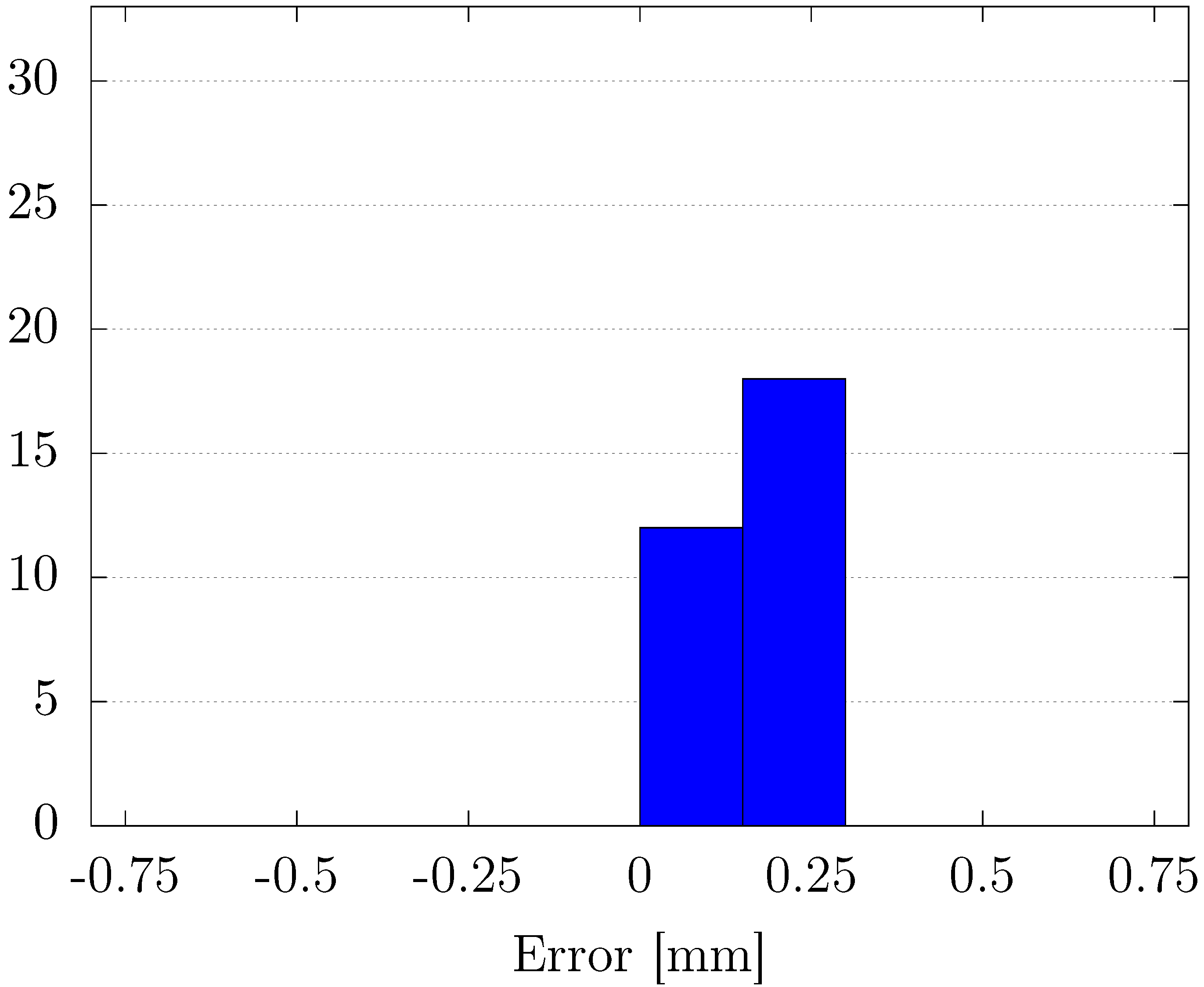
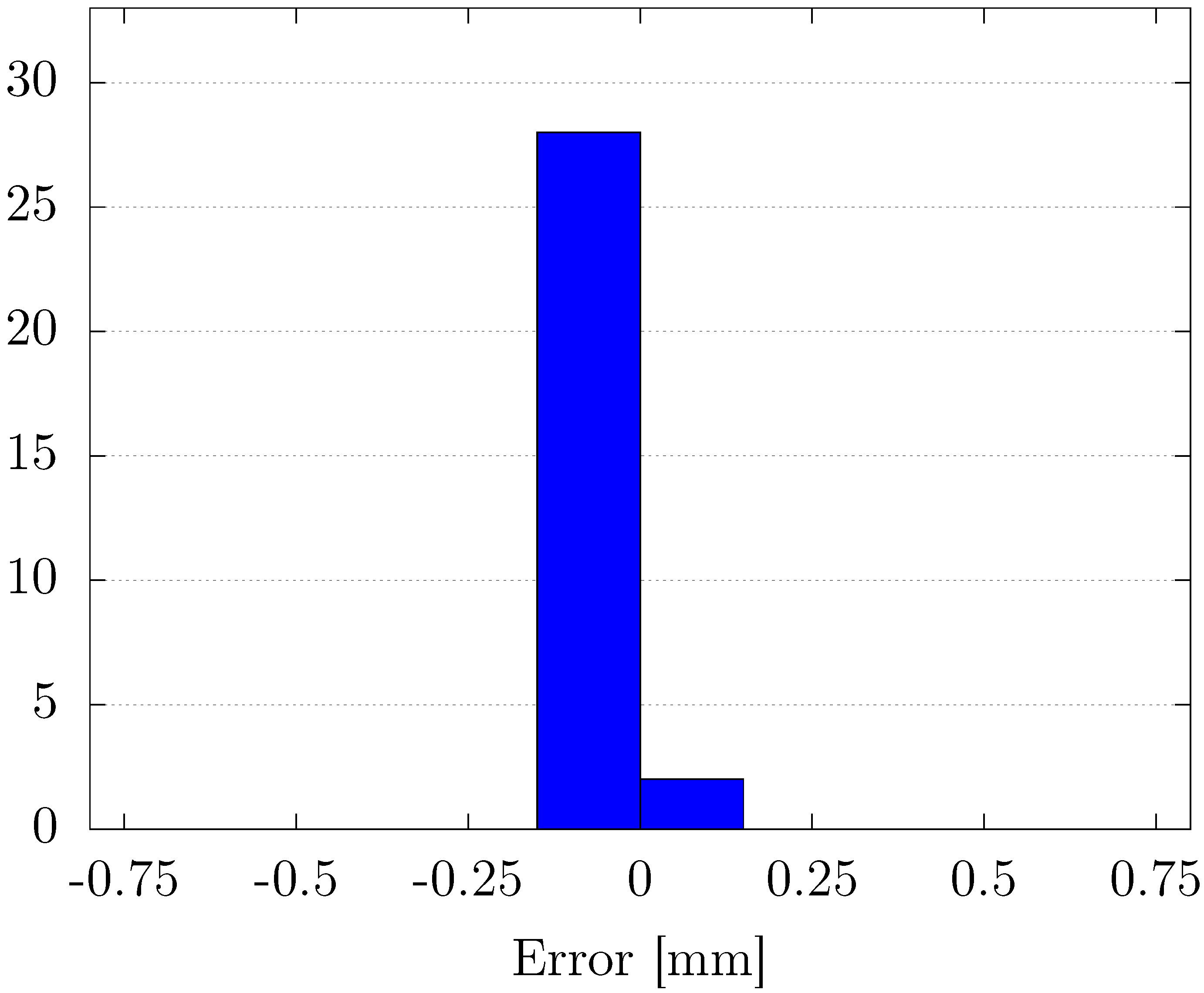
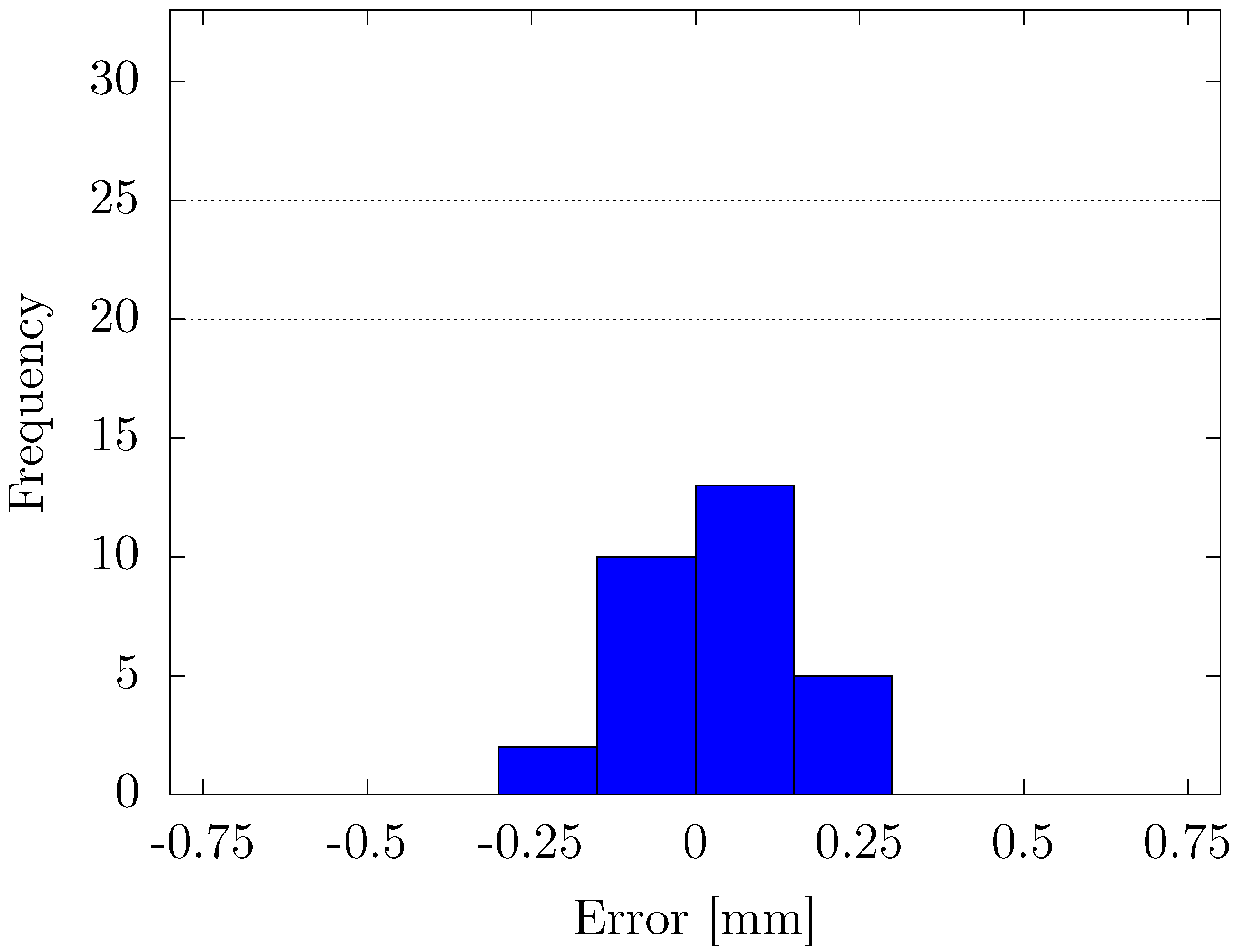
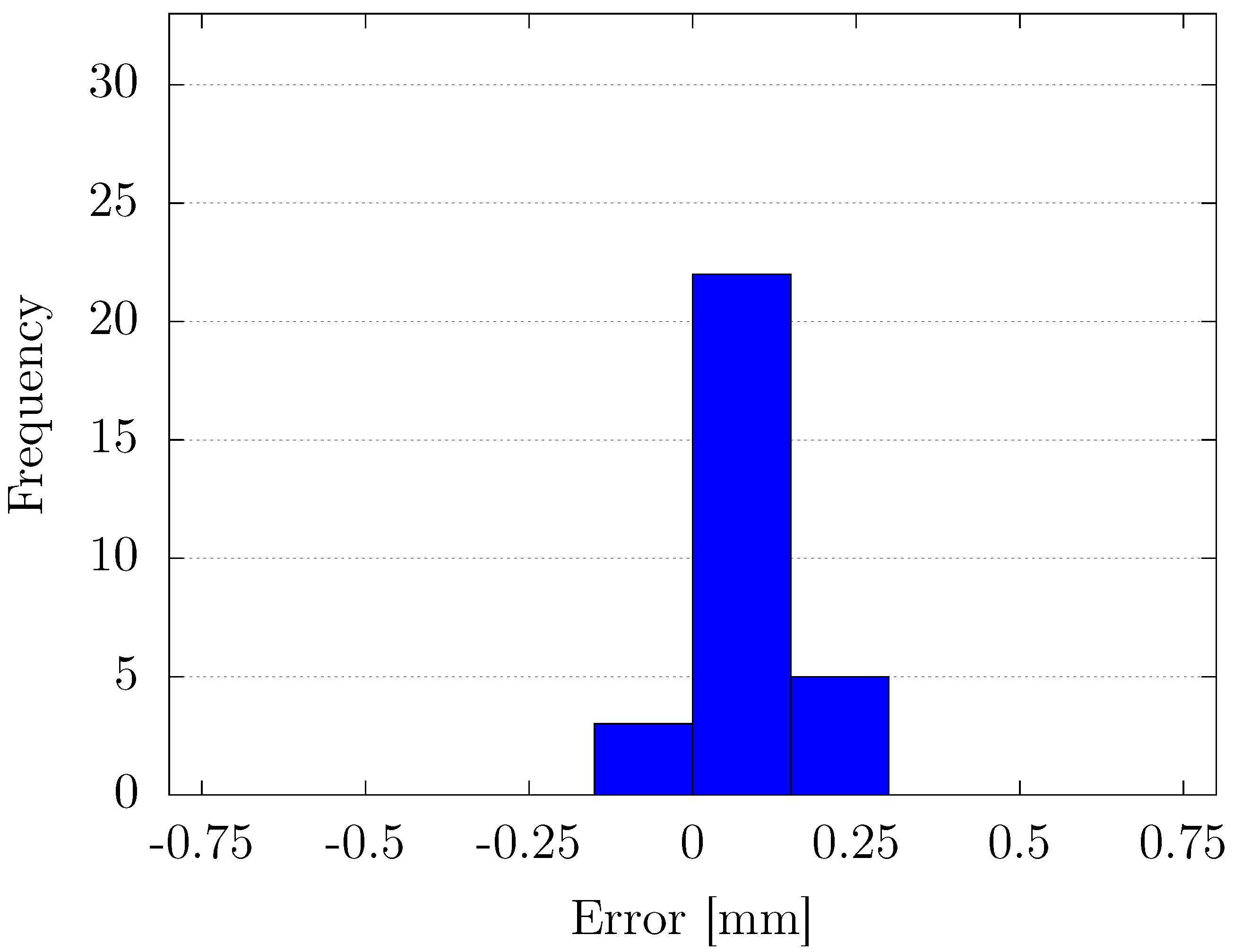
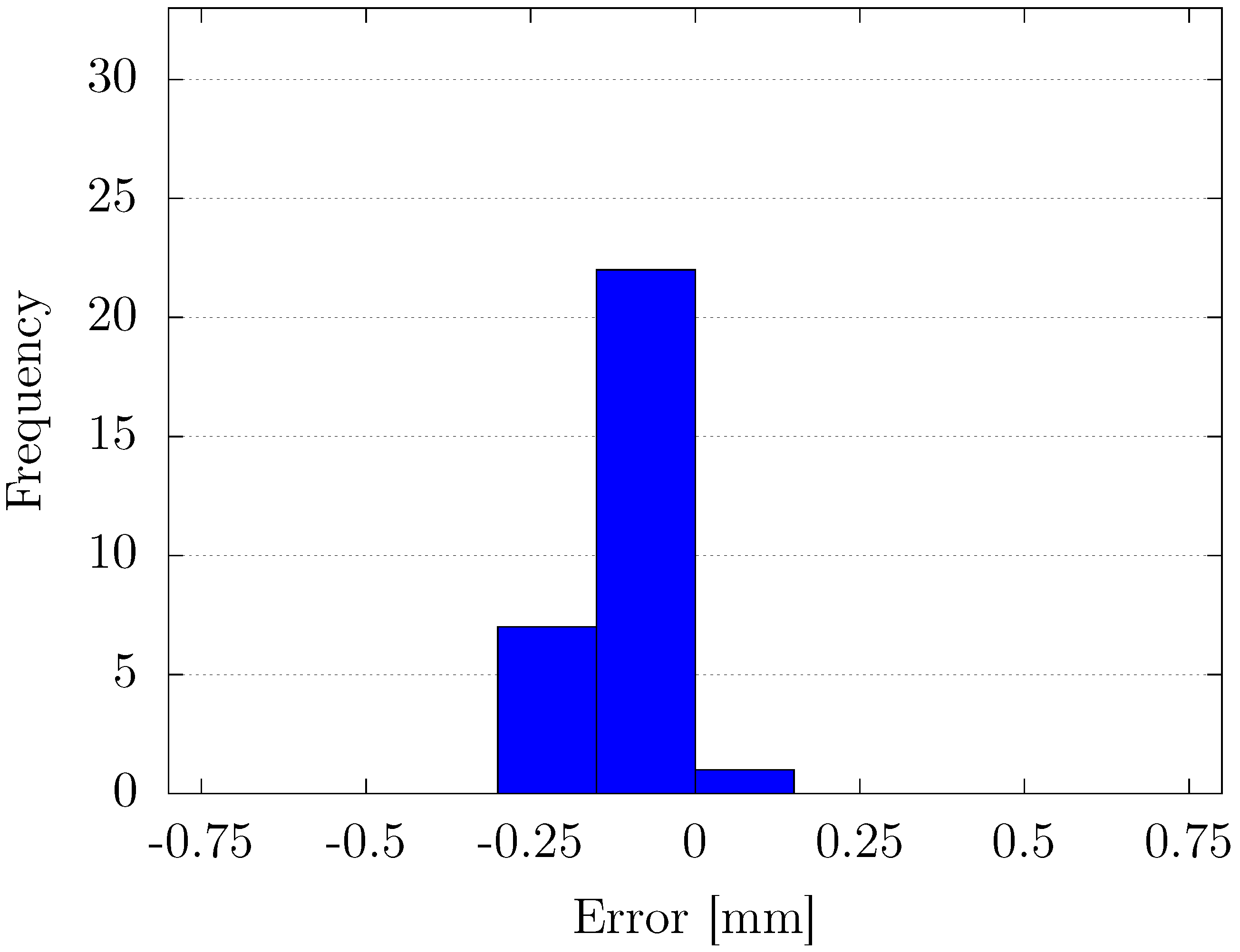
Figure 10 and Figure 11 illustrate histograms of steady-state positioning errors when a conventional fixed-gain PID controller is used under two target positions: +75 mm and −75 mm, respectively. In the case of the +75 mm target (Figure 10), most of the positioning errors fall within the range of +0.075 mm to 0.25 mm, showing a significant positive bias. The distribution is skewed and clearly offset from zero, indicating the controller’s inability to fully compensate for steady-state errors in this direction. For the −75 mm target (Figure 11), the histogram shows that nearly all of the samples are concentrated around 0mm, within the range of approximately −0.25 mm to 0 mm. This implies that the PID gains used here happen to be more effective in the negative direction of motion. The contrast between the two cases reveals a well-known limitation of fixed-gain PID control in nonlinear or asymmetric systems: the inability to account for direction-dependent dynamics or varying load conditions. The static nature of the control gains prevents adaptation to such variations, leading to asymmetric performance.
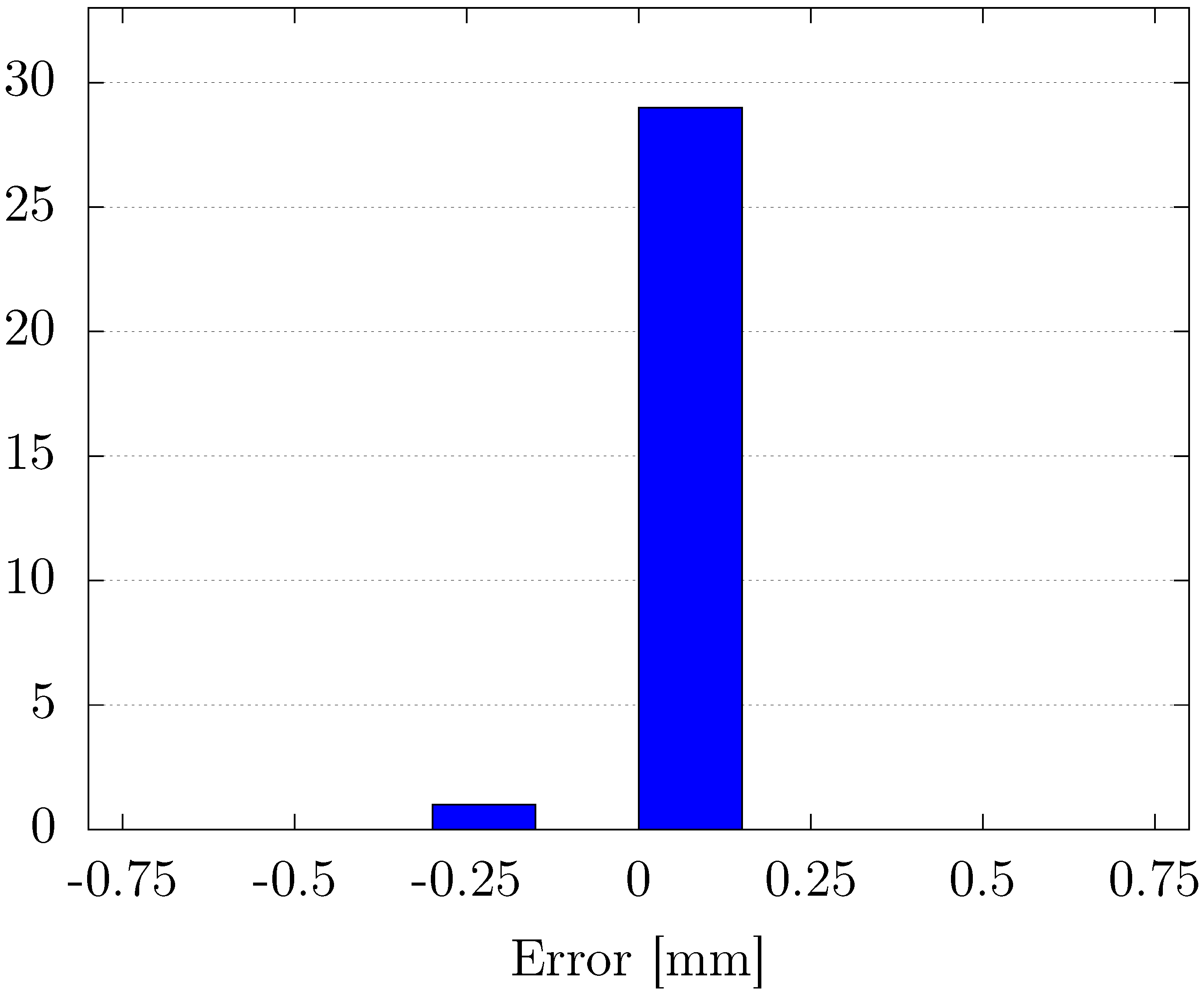
Figure 12 and Figure 13 show the corresponding histograms for the proposed control scheme, which incorporates the proposed OPSO-type NN-PID method. At the +75 mm target (Figure 12), nearly all the steady-state errors are tightly distributed around zero, falling within the range of approximately −0.075 mm to +0.075 mm. This sharply peaked and symmetric distribution around the origin demonstrates high precision and excellent steady-state performance.
At the −75 mm target (Figure 13), the error distribution is also centered near zero, with most errors lying within a similar ±0.075 mm range. Compared to the conventional PID, both the bias and the spread of the errors are significantly reduced. These results clearly demonstrate that the proposed controller effectively eliminates the asymmetry and offset observed in the fixed-gain PID case. The use of an online OPSO-tuned NN allows the control parameters to adapt in real time to changing plant dynamics, directional effects, and nonlinearity-capabilities that are crucial in pneumatic servo systems and other nonlinear applications.
Under the no-load condition, the proposed OPSO-NN-PID controller achieves high centrality of error distributions around 0 mm, low variance in both directions, and directional consistency, mitigating the asymmetry observed in the fixed-gain case. It demonstrates the effectiveness of incorporating adaptive mechanisms such as OPSO and NN in the control of nonlinear and asymmetric systems.
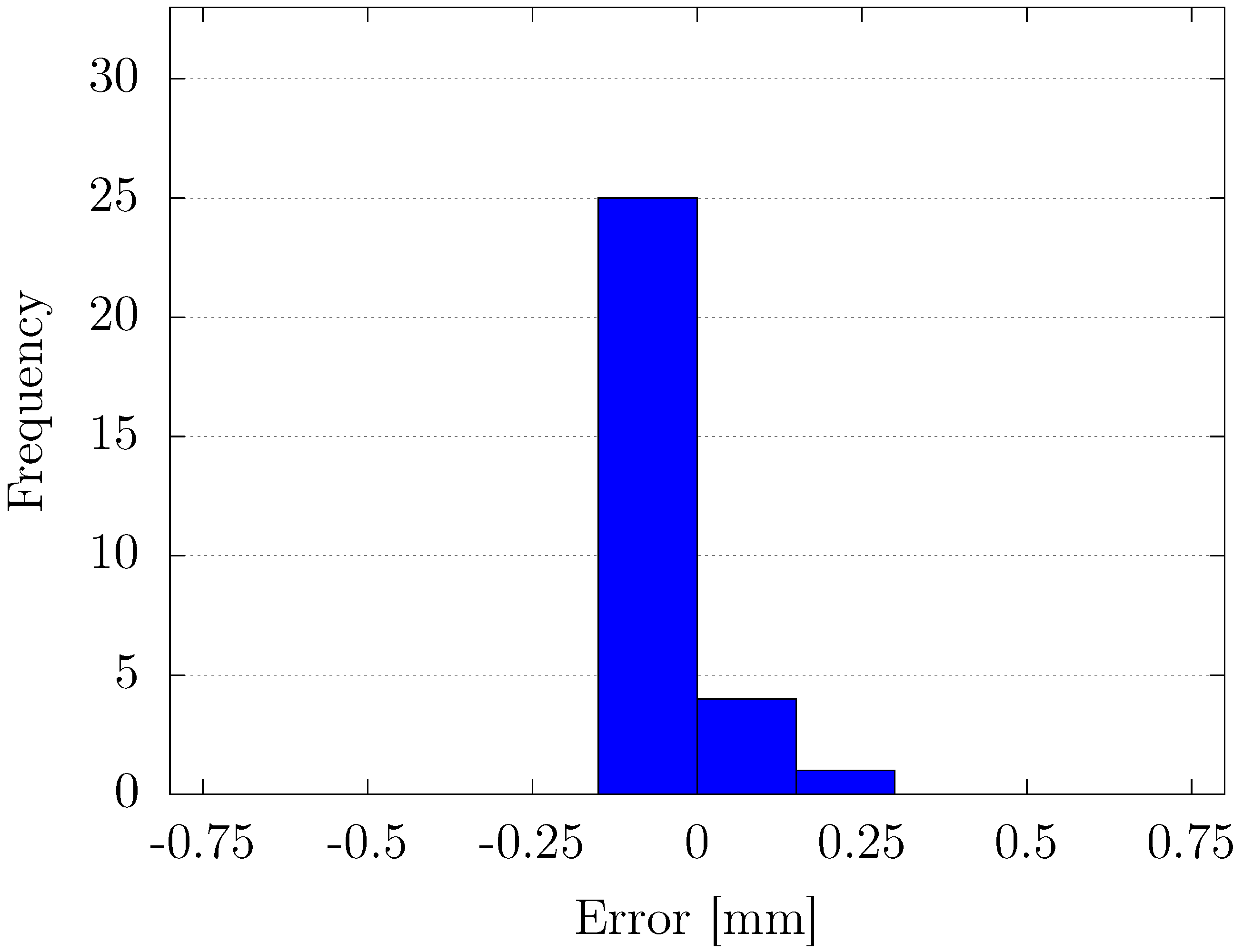
To assess the robustness of both control methods, a constant load was applied to the system, and steady-state positioning performance was re-evaluated under the same conditions at target positions of +75 mm and −75 mm. Figure 14, Figure 15, Figure 16 and Figure 17 illustrate the corresponding histogram results. Figure 14 and Figure 15 present the histograms of steady-state errors for the proposed control method at +75 mm and −75 mm. As shown in Figure 14, the histogram representing the steady-state error at the +75 mm target position shows that the errors are primarily concentrated around −0.1 mm to 0 mm. Most errors fall within a narrow band between −0.2 mm and 0.2 mm, with the highest frequency of errors centered near −0.1 mm. The slight negative bias toward −0.1 mm suggests a tendency for the control system to undershoot the target slightly, although the overall error magnitude remains in a small range. This error distribution indicates that the control system performs effectively at the +75 mm, demonstrating minimal deviations from the reference position. As shown in Figure 15, the histogram for the −75 mm objective position exhibits a tighter clustering of errors, mostly between −0.2 mm and 0.1 mm. The peak of the error distribution occurs near −0.1mm, indicating that the system also has a tendency to undershoot the target at −75 mm, similar to the +75 mm case. However, the errors at the −75 mm position are slightly more concentrated around zero, with fewer positive errors compared to the +75 mm target. This suggests slightly better performance in avoiding overshoot when the target is negative. According to the result of the position of the proposed method, it demonstrates excellent control accuracy, with steady-state errors confined to a narrow range around the target values. At both +75 mm and −75 mm, there is a slight tendency to undershoot the target, with the peak error frequency occurring at around −0.1 mm in both histograms. While the performance is comparable at both target positions, the error distribution at −75 mm is slightly more concentrated, reflecting greater consistency and fewer outliers in the negative target region.
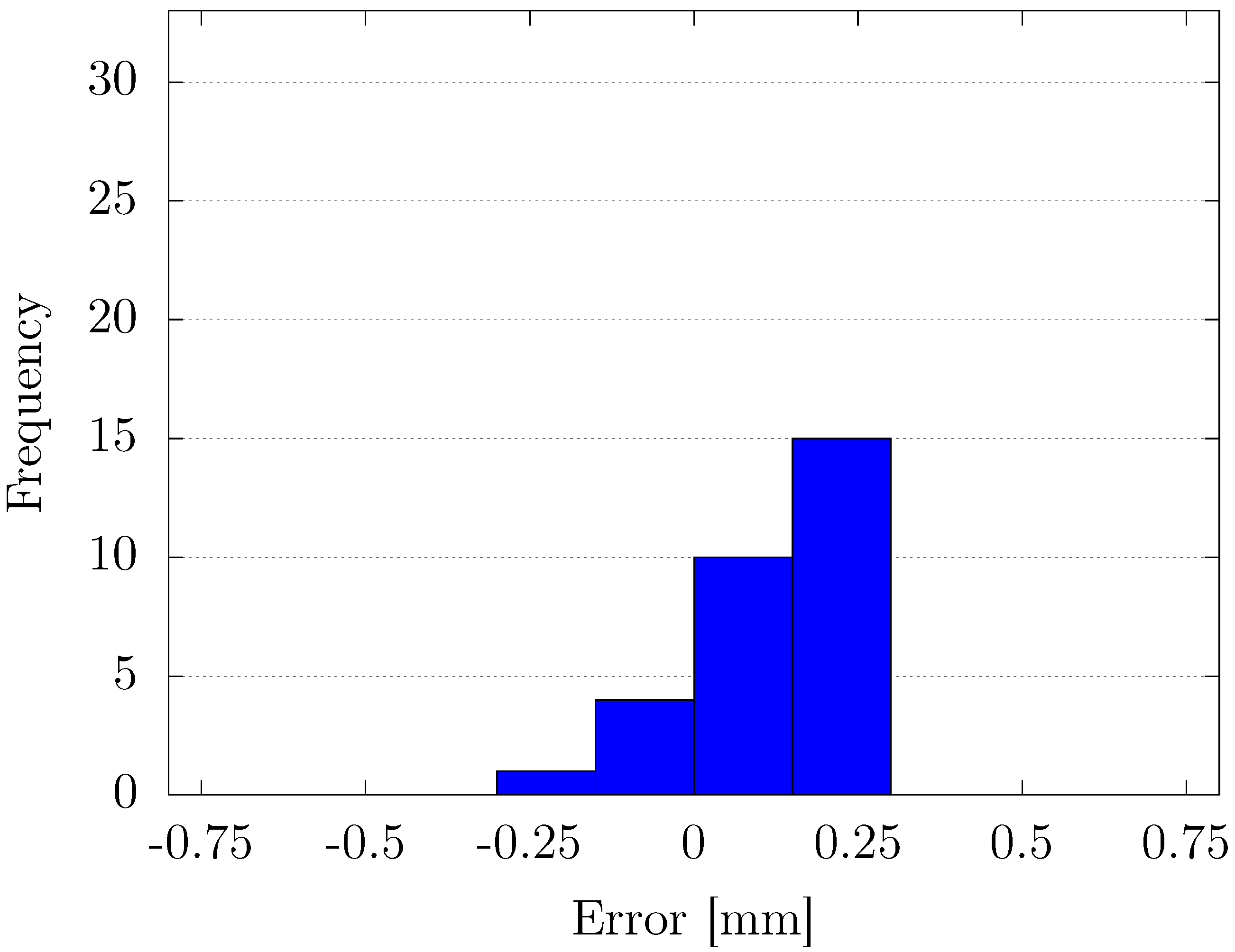
Figure 16 and Figure 17 show the performance of the proposed NN-PID controller with OPSO under the same load conditions. At +75 mm with load (Figure 16), the error distribution remains tightly centered around zero, with most values falling in the ± 0.075 mm range. Despite the presence of an external load, the control accuracy is only marginally affected, indicating good adaptability and load compensation capability. At −75 mm with load (Figure 17), the histogram shows a slight bias toward the negative direction, but the overall distribution remains compact and centered between −0.25 mm and 0 mm. Compared to the fixed PID counterpart, the spread is narrower and more balanced. These results confirm that the proposed method effectively maintains performance even under the load condition. The OPSO-type NN continuously optimizes PID parameters online, allowing the controller to adapt to time-varying or load-induced changes in system behavior.

4.2. Position Experiment Under Load Change

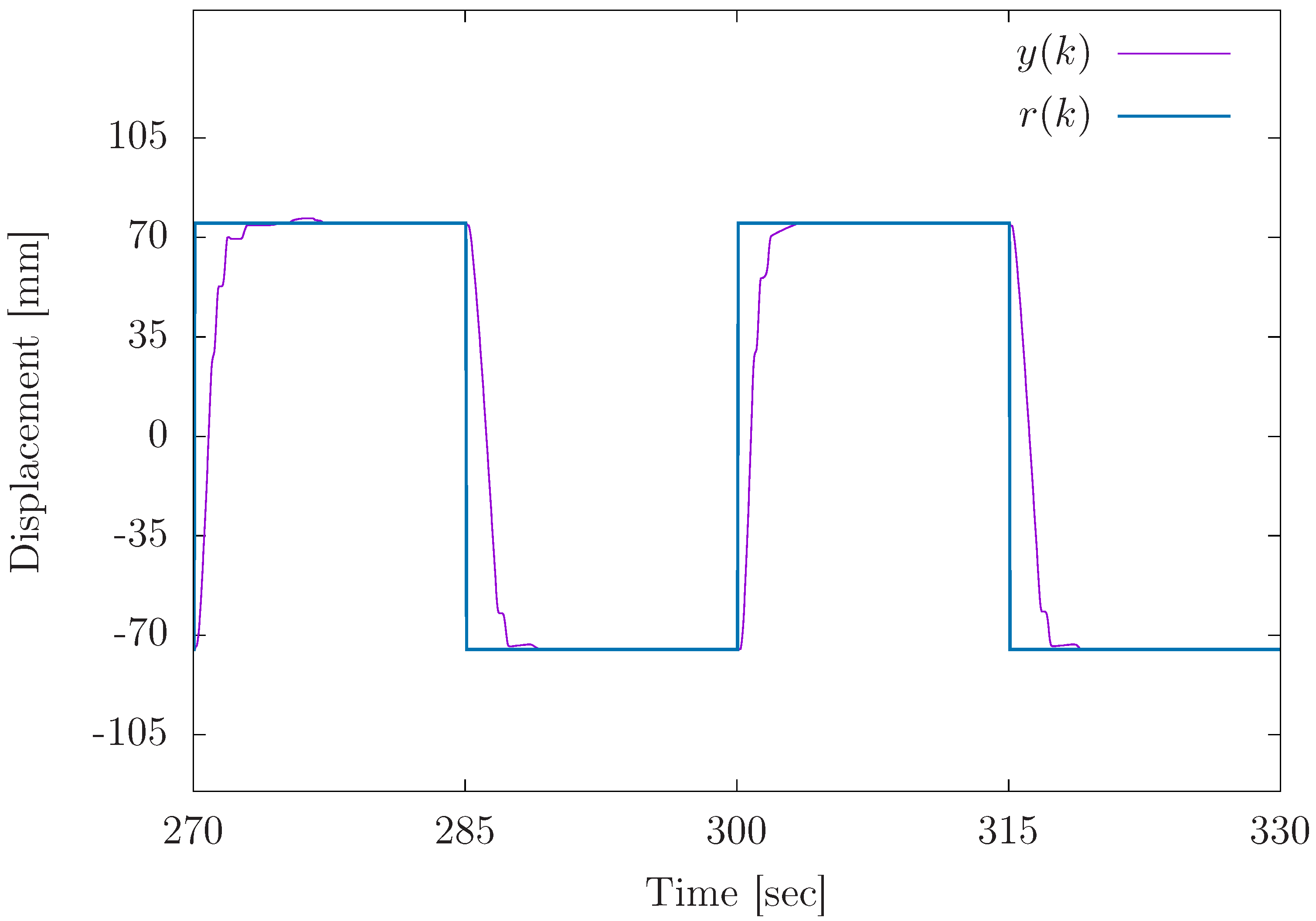
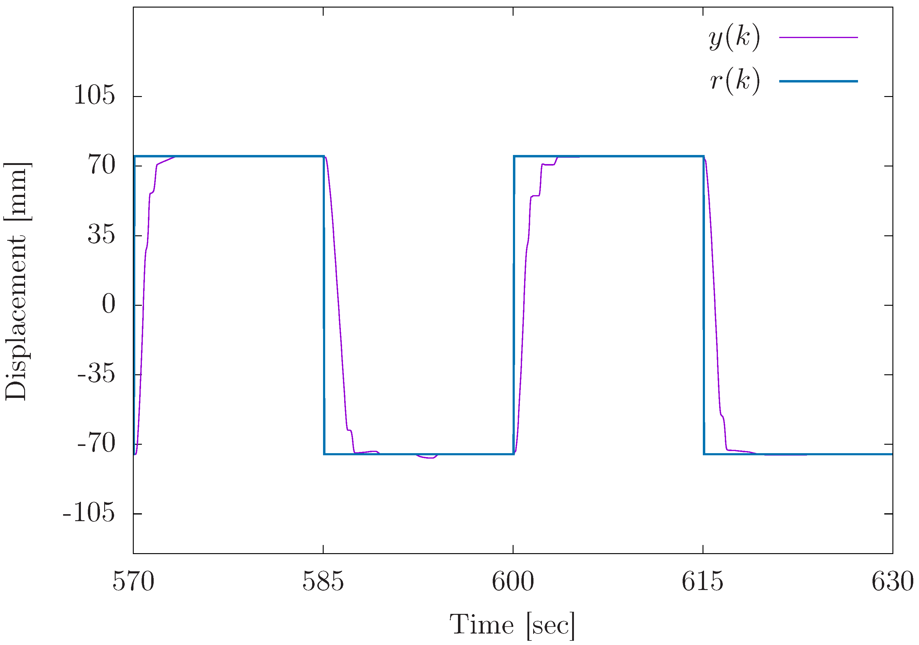
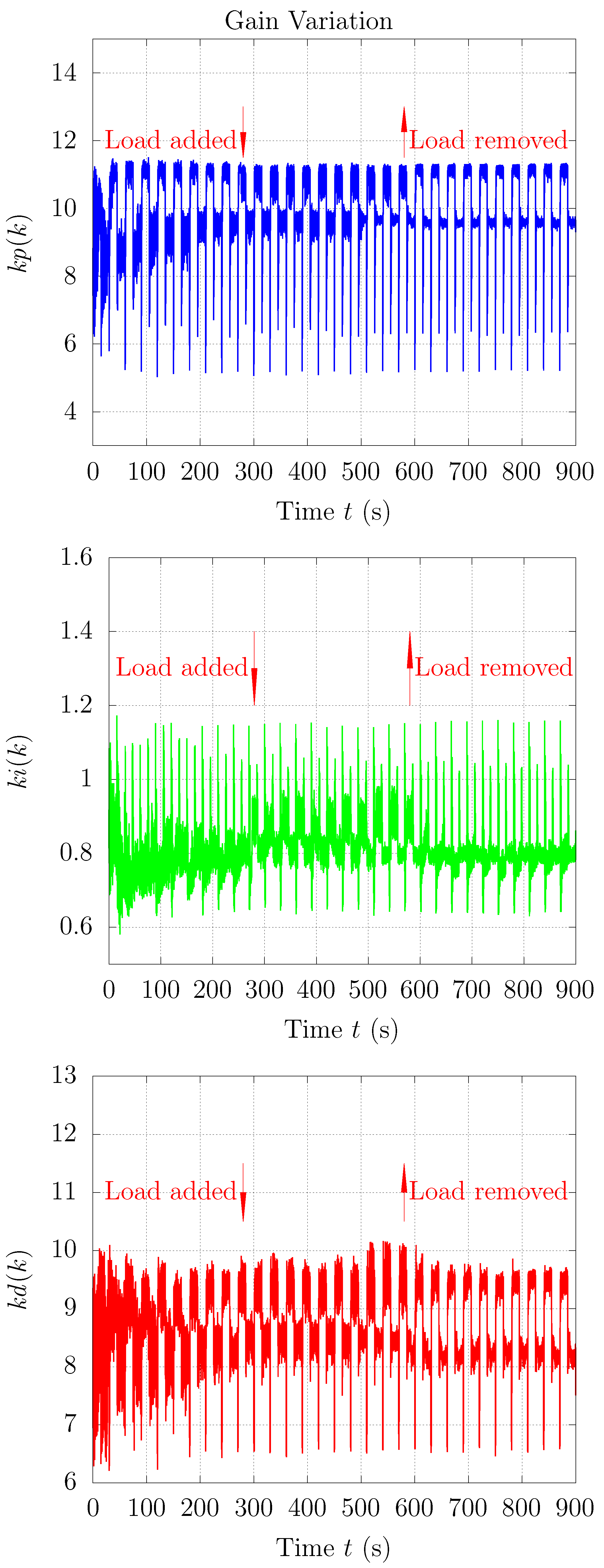
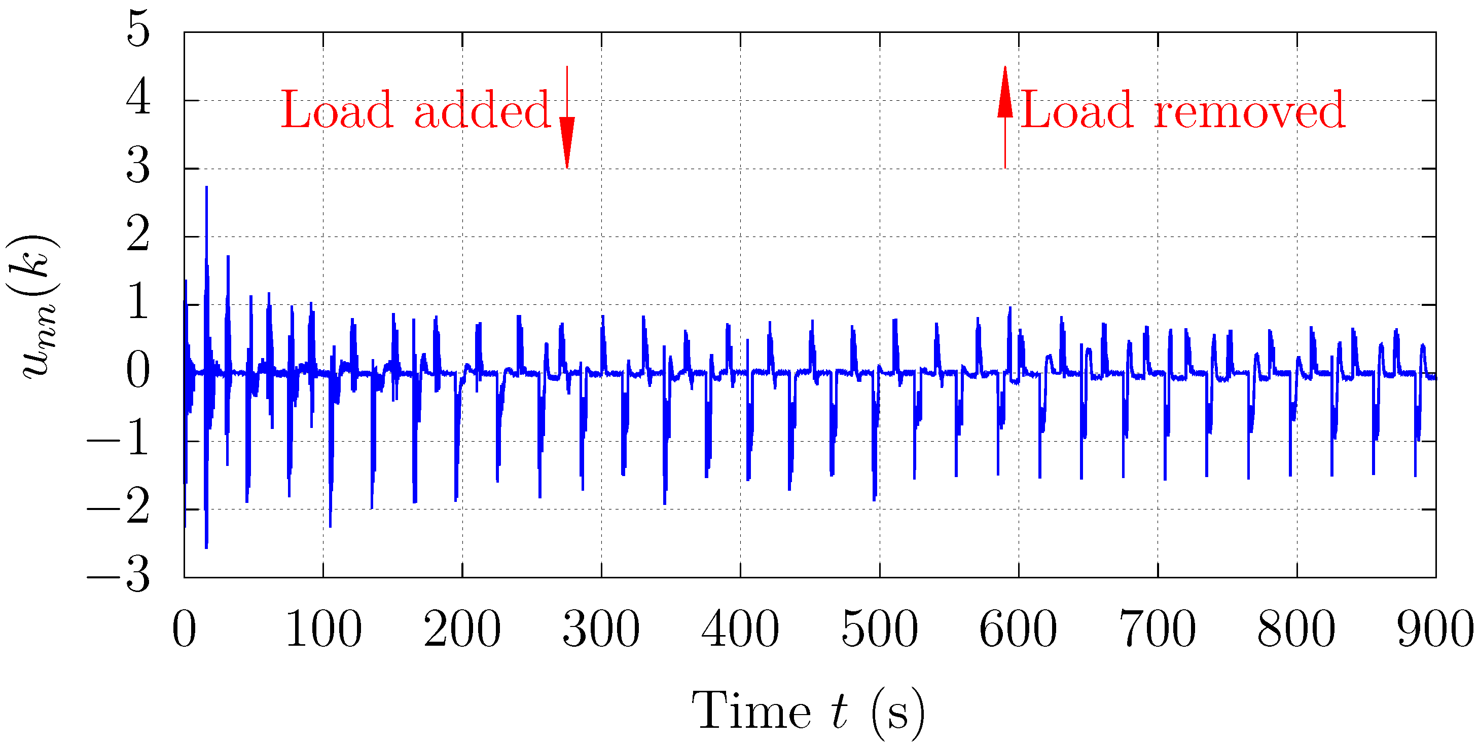
To evaluate the adaptability and dynamic robustness of the proposed OPSO-type NN-PID control scheme, an external lateral load of 10N was manually added to the pneumatic cylinder system at approximately 280 [s] and later removed at 590 [s]. The reference signal was a square wave of 75 mm to confirm the position tracking capability under repetitive large-amplitude motion. The results are shown in Figure 18, Figure 19, Figure 20 and Figure 21.
Figure 18 and Figure 19 present the system-displacement output y ( k ) and the reference input r ( k ) under the proposed method. The output trajectory shows only a minor and momentary deviation immediately after the load is added or removed. No sustained overshoot or oscillation is observed, and the system quickly re-converges to the reference trajectory within approximately 1–2 [s]. This indicates excellent real-time adaptability and the rejection of external-force disturbances. The PID parameters K p ( k ) , K i ( k ) , and K d ( k ) were dynamically optimized online via OPSO to respond to system variations. The parameter evolution shown in Figure 20 was tuned to moderate the system’s responsiveness, effectively reducing overshoot and amplitude deviation during load transitions. As shown in Figure 21, the compensatory control input u n n ( k ) responded instantly at ~280 [s] and ~590 [s], when the load was added and removed. This signal introduced an additional feedforward compensation, counteracting the unmodeled dynamics introduced via the external force. The smooth and bounded nature of u n n ( k ) indicates that it played a non-disruptive, stabilizing role in transient behavior. The experiment confirms that the proposed OPSO-NN control method ensures stable and accurate tracking, even in the presence of external forces. The integration of OPSO-NN-based PID parameter tuning with a supplemental compensation output prevents output overshoot by dynamically adjusting controller responsiveness. It suppresses error accumulation through feedforward compensation. It also maintains low errors and a fast response time under both load-on and load-off conditions with robustness and adaptability, making the proposed method highly suitable for uncertain, nonlinear systems such as pneumatic actuators, especially where real-time force fluctuations are prevalent.

5. Conclusions

In this study, an advanced variable-gain PID control method for pneumatic servo systems, utilizing an optimized particle swarm optimization-type neural network to address the system’s inherent nonlinearities, was implemented. By integrating two OPSO-type NNs, the controller demonstrated improved accuracy and adaptability in tuning PID gains dynamically, which resulted in enhanced control performance.
Through experimental validation, we confirmed that the proposed method outperformed conventional fixed-gain PID control in terms of position-tracking accuracy, transient response, and steady-state error reduction. Specifically, the proposed controller achieved faster settling times and minimized overshoot, particularly in response to abrupt changes in the reference signal. Additionally, the steady-state error analysis revealed that the variable-gain control method consistently provided more precise results, with errors concentrated in narrower ranges at both positive and negative displacement targets. Despite its effectiveness, some variability in steady-state performance was noted, indicating areas for future improvement, particularly in fine-tuning the inertia coefficient of the sub-swarm to further optimize control precision. Compared to traditional fixed-gain PID methods, our OPSO-NN method uniquely integrates hierarchical swarm optimization into real-time PID tuning, significantly enhancing system adaptability and control precision.
Future work will explore these improvements and extend the method’s validation under higher load conditions. The results of this study highlight the potential of the OPSO-NN method as a robust and adaptable control strategy, offering significant advantages over traditional PID control approaches for complex systems like pneumatic servo mechanisms.
Author Contributions

Conceptualization, S.M. and S.S.; methodology, S.M. and S.S.; software, D.B. and R.O.; validation, S.M., S.S., D.B. and R.O.; formal analysis, S.M.; investigation, S.S.; resources, S.S.; data curation, S.M.; writing—original draft preparation, S.M.; writing—review and editing, S.M.; visualization, S.M.; supervision, S.S.; project administration, S.S. All authors have read and agreed to the published version of the manuscript.

Funding

This research received no external funding.

Data Availability Statement

Data are contained within the article.

Conflicts of Interest

The authors declare no conflicts of interest.

References

  1. Shibata, S.; Jindai, M.; Yamamoto, T.; Shimizu, A. Neuro-Fuzzy Control for Pneumatic Servo System. JSME Int. J. Ser. Mech. Syst. Mach. Elem. Manuf. 2002, 45, 449–455. [Google Scholar] [CrossRef]
  2. Mu, S.; Goto, S.; Shibata, S.; Yamamoto, T. Intelligent position control for pneumatic servo system based on predictive fuzzy control. Comput. Electr. Eng. 2019, 75, 112–122. [Google Scholar] [CrossRef]
  3. Zhao, L.; Yang, Y.; Xia, Y.; Liu, Z. Active Disturbance Rejection Position Control for a Magnetic Rodless Pneumatic Cylinder. IEEE Trans. Ind. Electron. 2015, 62, 5838–5846. [Google Scholar] [CrossRef]
  4. Deng, W.; Yao, J. Asymptotic Tracking Control of Mechanical Servosystems With Mismatched Uncertainties. IEEE/ASME Trans. Mechatron. 2021, 26, 2204–2214. [Google Scholar] [CrossRef]
  5. Gu, S.; Zhang, J. Variable gain ADRC for delta parallel manipulators with disturbances. Control Eng. Pract. 2024, 145, 105877. [Google Scholar] [CrossRef]
  6. Gu, S.; Zhang, J.; Liu, X. Event-Triggered Finite-Time Variable Gain ADRC for Master–Slave Teleoperated Parallel Manipulators. IEEE Trans. Circuits Syst. II Express Briefs 2024, 71, 3383–3387. [Google Scholar] [CrossRef]
  7. Zhang, J.; Lu, B.; Chen, C.; Li, Z. A New Active Disturbance Rejection Control Tuning Method for High-Order Electro-Hydraulic Servo Systems. Actuators 2024, 13, 296. [Google Scholar] [CrossRef]
  8. Herbst, G.; Madonski, R. Tuning and implementation variants of discrete-time ADRC. Control Theory Technol. 2023, 21, 72–88. [Google Scholar] [CrossRef]
  9. Zhao, L.; Gu, S.; Zhang, J.; Li, S. Finite-Time Trajectory Tracking Control for Rodless Pneumatic Cylinder Systems with Disturbances. IEEE Trans. Ind. Electron. 2022, 69, 4137–4147. [Google Scholar] [CrossRef]
  10. Sun, H.; Gao, L.; Zhao, Z.; Li, B. Finite-time active disturbance rejection control for high-pressure pneumatic servo system subject to matched and mismatched disturbances. In Proceedings of the 9th International Conference on Fluid Power and Mechatronics (FPM), Lanzhou, China, 18–21 August 2023. [Google Scholar] [CrossRef]
  11. Li, J.; Tanaka, K. Intelligent Control for Pneumatic Servo System. JSME Int. J. Ser. Mech. Syst. Mach. Manuf. 2003, 46, 699–704. [Google Scholar] [CrossRef]
  12. Jiang, F.; Zhang, W.; Chen, J. Prediction of Output Force of Pneumatic System Using BP Neural Network. J. Physics Conf. Ser. 2022, 2402, 012011. [Google Scholar] [CrossRef]
  13. Chen, Y.; Tao, G.; Liu, H. High Precision Adaptive Robust Neural Network Control of a Servo Pneumatic System. Appl. Sci. 2019, 9, 3472. [Google Scholar] [CrossRef]
  14. Taniguchi, A.; Mu, S.; Shibata, S.; Yamamoto, T. An Intelligent PID Control using Neural Networks for Pneumatic Servo Systems. In Proceedings of the International Symposium on Computer, Consumer and Control (IS3C), Taichung City, Taiwan, 13–16 November 2020; pp. 549–552. [Google Scholar] [CrossRef]
  15. Kennedy, J.; Eberhart, R. Particle swarm optimization. In Proceedings of the IEEE International Conference Neural Networks, Perth, WA, Australia, 27 November–1 December 1995; Volume 4, pp. 1942–1948. [Google Scholar]
  16. Zhang, Y.; Wang, S.; Ji, G. A Comprehensive Survey on Particle Swarm Optimization Algorithm and Its Applications. Math. Probl. Eng. 2015, 2015, 931256. [Google Scholar] [CrossRef]
  17. Shami, T.; El-Saleh, A.; Alswaitti, M.; Al-Tashi, Q.; Summakieh, M.; Mirjalili, S. Particle Swarm Optimization: A Comprehensive Survey. IEEE Access 2022, 10, 10031–10061. [Google Scholar] [CrossRef]
  18. Lin, C.; Chen, C.; Lin, C. A Hybrid of Cooperative Particle Swarm Optimization and Cultural Algorithm for Neural Fuzzy Networks and Its Prediction Applications. IEEE Trans. Syst. Man Cybern. Part C Appl. Rev. 2009, 39, 55–68. [Google Scholar]
  19. Chen, J.; Do, Q.; Hsieh, H. Training Artificial Neural Networks by a Hybrid PSO-CS Algorithm. Algorithms 2015, 8, 292–308. [Google Scholar] [CrossRef]
  20. Mirjalili, S.; Hashim, S.; Sardroudi, H. Training feedforward neural networks using hybrid particle swarm optimization and gravitational search algorithm. Appl. Math. Comput. 2012, 218, 11125–11137. [Google Scholar] [CrossRef]
  21. Meissner, M.; Schmuker, M.; Schneider, G. Optimized Particle Swarm Optimization (OPSO) and its application to artificial neural network training. BMC Bioinform. 2006, 7, 125. [Google Scholar] [CrossRef] [PubMed]
  22. Tanaka, K.; Sakata, K.; Shimizu, A. Adaptive Pole-Placement Control for Pneumatic Servo Systems with Disturbances. Trans. Soc. Instrum. Control Eng. 1994, 30, 1069–1076. [Google Scholar] [CrossRef]
Figure 1. This figure illustrates the pneumatic servo system we applied in our research on precision position control. This system comprises the key components of a cylinder, valves, mass, a magnescale, a power amplifier, a D/A converter, a counter board, and a computer to obtain high performance in position control.
Actuators 14 00250 g001
Figure 2. This figure illustrates the pneumatic servo system equipped for precise servo control in our study. The pneumatic cylinder converts compressed air into horizontal motion, enabling the movement of the attached mass. The pneumatic cylinder is a double-acting cylinder with both rods, having an inner diameter of 55 mm, a stroke of 170 mm, and a rod diameter of 22 mm. Two 3-way proportional pressure control valves are applied to regulate the airflow to the cylinder. A magnescale is used for position detection.
Actuators 14 00250 g002
Figure 3. The figure illustrates the relationship between input voltage and pressure in the pneumatic servo system. The x-axis represents the input voltage (in volts), ranging from 2 to 5 V, while the y-axis indicates the resulting pressure (in megapascals, MPa), spanning from 0.1 to 0.5 MPa.
Actuators 14 00250 g003
Figure 4. The figure illustrates the pressure response in the cylinder.
Actuators 14 00250 g004
Figure 5. The figure presents the block diagram of the PID control system.
Actuators 14 00250 g005
Figure 6. This figure illustrates the proposed architecture that integrates a PID controller using two OPSO-type NNs, designated as OPSO-NN1 and OPSO-NN2. The proposed hybrid approach was designed to enhance the control performance in precise control of the servo system.
Actuators 14 00250 g006
Figure 7. The structure of the NN designed to tune the PID gains of the pneumatic servo system in the OPSO-NN1 of proposed method.
Actuators 14 00250 g007
Figure 8. The structure of the NN designed to estimate the compensation input for the pneumatic servo system in the OPSO-NN2 of the proposed method.
Actuators 14 00250 g008
Figure 9. Conceptual diagram illustrating the mechanics of particle swarm optimization.
Actuators 14 00250 g009
Figure 10. Histograms of steady-state errors for the fixed-gain PID control at +75 mm.
Actuators 14 00250 g010
Figure 11. Histograms of steady-state errors for the fixed-gain PID control at −75 mm.
Actuators 14 00250 g011
Figure 12. Histograms of steady-state errors for the proposed PID control using OPSO-type NN at +75 mm.
Actuators 14 00250 g012
Figure 13. Histograms of steady-state errors for the proposed PID control using OPSO-type NN at −75 mm.
Actuators 14 00250 g013
Figure 14. Histograms of steady-state errors for the fixed-gain PID control at +75 mm with load.
Actuators 14 00250 g014
Figure 15. Histograms of steady-state errors for the fixed-gain PID control at −75 mm with load.
Actuators 14 00250 g015
Figure 16. Histograms of steady-state errors for the proposed PID control using OPSO-type NN at +75 mm with load.
Actuators 14 00250 g016
Figure 17. Histograms of steady-state errors for the proposed PID control using OPSO-type NN at −75 mm with load.
Actuators 14 00250 g017
Figure 18. Response of square wave with load added at around 280 [s].
Actuators 14 00250 g018
Figure 19. Response of square wave with load added at around 590 [s].
Actuators 14 00250 g019
Figure 20. Variation in the PID gains of the proposed method.
Actuators 14 00250 g020
Figure 21. Variation in u n n ( k ) in the proposed method.
Actuators 14 00250 g021
Table 1. Parameters of pneumatic servo system.
Pneumatic Cylinder StructureDouble-Acting Cylinder with Both Rods
inner diameter55 mm
rod diameter22 mm
position detection range500 mm
stroke length170 mm
resolution of position detection5 µm
sampling time0.04 s
Table 2. Initial gain values for the fixed-gain PID control and the proposed PID control using an OPSO-type NN.
Objective Value K P K I K D
±75 mm7.70.87.5
Table 3. Initial parameters of the proposed PID control using an OPSO-type NN.
Inertia Weight of Super-Swarm g0.9
acceleration coefficients C 1 , C 2 2.0
particle number of super-swarm10
particle number of sub-swarm30
Disclaimer/Publisher’s Note: The statements, opinions and data contained in all publications are solely those of the individual author(s) and contributor(s) and not of MDPI and/or the editor(s). MDPI and/or the editor(s) disclaim responsibility for any injury to people or property resulting from any ideas, methods, instructions or products referred to in the content.